以下、本発明の実施の形態について、図面を参照して詳細に説明する。
Hereinafter, embodiments of the present invention will be described in detail with reference to the drawings.
(実施の形態1)
図1は、本発明の実施の形態1に係る撮影システム100の構成を示すブロック図である。撮影システム100は、撮影装置150及びストロボ装置160を含む。本実施の形態において、撮影装置150及びストロボ装置160は、何れも携帯電話等の通信端末装置である。なお、撮影装置150及びストロボ装置160は、通信端末装置である場合に限らず、任意の装置にすることができる。また、撮影システム100において、ストロボ装置160は、1つに限らず複数存在する場合もあるが、図1では説明の都合上、ストロボ装置160を1つだけ記載し、他のストロボ装置の記載は省略する。
(Embodiment 1)
FIG. 1 is a block diagram showing a configuration of an imaging system 100 according to Embodiment 1 of the present invention. The photographing system 100 includes a photographing device 150 and a strobe device 160. In the present embodiment, the photographing device 150 and the flash device 160 are both communication terminal devices such as mobile phones. Note that the image capturing device 150 and the flash device 160 are not limited to communication terminal devices, and can be arbitrary devices. In the photographing system 100, there may be a plurality of strobe devices 160 instead of one, but in FIG. 1, only one strobe device 160 is shown for convenience of explanation, and other strobe devices are not shown. Omitted.
最初に、撮影装置150の構成について、図1を用いて説明する。
First, the configuration of the photographing apparatus 150 will be described with reference to FIG.
指示手段としての閃光体管理部101は、ストロボ装置160から送信されたACK信号が撮影制御部103から入力した場合に、ACK信号からストロボ装置160固有のIDを抽出する。また、閃光体管理部101は、撮影部104に設けた撮影のためのシャッターが操作された検出結果が撮影制御部103から入力した際に、通信制御部105に対して、ストロボ装置160にストロボ発光を指示するための発光指示信号の生成を要求する。また、その際に、閃光体管理部101は、ストロボ発光を指示するストロボ装置160のIDを通信制御部105へ出力する。
When the ACK signal transmitted from the flash device 160 is input from the photographing control unit 103, the flash body management unit 101 as an instruction unit extracts an ID unique to the flash device 160 from the ACK signal. In addition, the flash management unit 101 sends a strobe device 160 to the strobe device 160 with respect to the communication control unit 105 when a detection result obtained by operating a shutter for shooting provided in the shooting unit 104 is input from the shooting control unit 103. It requests generation of a light emission instruction signal for instructing light emission. At that time, the flash management unit 101 outputs the ID of the strobe device 160 that instructs strobe emission to the communication control unit 105.
タイマ102は、タイマ値をカウントアップする。また、タイマ102は、リセットの指示を受けてタイマ値をリセットする。
The timer 102 counts up the timer value. The timer 102 resets the timer value upon receiving a reset instruction.
撮影制御部103は、通信制御部105からACK信号が入力した場合に、LEDを点灯する等により撮影が可能であることを報知する。そして、撮影制御部103は、入力したACK信号を閃光体管理部101へ出力する。また、撮影制御部103は、撮影部104に設けた撮影のためのシャッターの操作を検出し、検出結果を閃光体管理部101へ出力する。
When an ACK signal is input from the communication control unit 105, the shooting control unit 103 notifies that shooting is possible by turning on an LED or the like. Then, the imaging control unit 103 outputs the input ACK signal to the flash body management unit 101. Further, the photographing control unit 103 detects an operation of a shutter for photographing provided in the photographing unit 104 and outputs the detection result to the flash body management unit 101.
撮影部104は、撮影のためのシャッターを有する。また、撮影部104は、シャッターの押圧等のシャッターが操作された際に撮影を行う。
The photographing unit 104 has a shutter for photographing. The photographing unit 104 performs photographing when the shutter is operated such as pressing the shutter.
探索手段としての通信制御部105は、ストロボ装置160を探索するための探索信号を生成する。例えば、通信制御部105は、電話帳情報に登録されているストロボ装置160、または撮影前にIrDA(Infrared Data Association)等を用いて一対一通信を行うことによりあらかじめ認識して記憶しておいたストロボ装置160を、探索信号の宛先に設定する。また、通信制御部105は、閃光体管理部101からの要求に従って、閃光体管理部101から入力したIDのストロボ装置160を宛先とする発光指示信号を生成する。そして、通信制御部105は、設定されている通信方式に応じて近距離通信部106または指向性通信部107を選択し、選択した近距離通信部106または指向性通信部107へ探索信号または発光指示信号を出力する。また、通信制御部105は、近距離通信部106または指向性通信部107から入力した信号からACK信号を抽出し、抽出したACK信号を撮影制御部103へ出力する。通信制御部105は、ACK信号を抽出することにより、相手装置であるストロボ装置160を検出することができる。
The communication control unit 105 serving as a search unit generates a search signal for searching for the strobe device 160. For example, the communication control unit 105 recognizes and stores in advance by performing one-to-one communication using the strobe device 160 registered in the phone book information or the IrDA (Infrared Data Association) before photographing. The strobe device 160 is set as a search signal destination. Further, the communication control unit 105 generates a light emission instruction signal whose destination is the strobe device 160 with the ID input from the flash body management unit 101 in accordance with a request from the flash body management unit 101. Then, the communication control unit 105 selects the short-range communication unit 106 or the directional communication unit 107 according to the set communication method, and sends a search signal or light emission to the selected short-range communication unit 106 or directional communication unit 107. An instruction signal is output. Further, the communication control unit 105 extracts an ACK signal from the signal input from the short-range communication unit 106 or the directional communication unit 107, and outputs the extracted ACK signal to the imaging control unit 103. The communication control unit 105 can detect the strobe device 160 that is the counterpart device by extracting the ACK signal.
近距離通信部106は、通信制御部105から入力した発光指示信号または探索信号を、近距離の無線通信が可能な信号に変換して送信する。また、近距離通信部106は、ストロボ装置160から送信された信号を受信し、受信した信号を通信制御部105で処理可能な信号に変換して通信制御部105へ出力する。
The short-range communication unit 106 converts the light emission instruction signal or search signal input from the communication control unit 105 into a signal that enables short-range wireless communication and transmits the signal. The short-range communication unit 106 receives a signal transmitted from the flash device 160, converts the received signal into a signal that can be processed by the communication control unit 105, and outputs the signal to the communication control unit 105.
指向性通信部107は、通信制御部105から入力した発光指示信号または探索信号を、赤外線(Ir)信号等の指向性を有する信号に変換して送信する。また、指向性通信部107は、ストロボ装置160から送信されたACK信号を受信し、受信したACK信号を通信制御部105で処理可能な信号に変換して通信制御部105へ出力する。
The directivity communication unit 107 converts the light emission instruction signal or the search signal input from the communication control unit 105 into a signal having directivity such as an infrared (Ir) signal and transmits the signal. Directivity communication unit 107 receives the ACK signal transmitted from strobe device 160, converts the received ACK signal into a signal that can be processed by communication control unit 105, and outputs the signal to communication control unit 105.
次に、ストロボ装置160の構成について、図1を用いて説明する。
Next, the configuration of the strobe device 160 will be described with reference to FIG.
近距離通信部111は、撮影装置150から送信された信号を受信し、受信した信号を通信制御部113で処理可能な信号に変換して通信制御部113へ出力する。また、近距離通信部111は、通信制御部113から入力したACK信号を、近距離の無線通信が可能な信号に変換して送信する。
The short-range communication unit 111 receives a signal transmitted from the imaging device 150, converts the received signal into a signal that can be processed by the communication control unit 113, and outputs the signal to the communication control unit 113. The short-range communication unit 111 converts the ACK signal input from the communication control unit 113 into a signal that enables short-range wireless communication and transmits the signal.
指向性通信部112は、撮影装置150から送信された信号を受信し、受信した信号を通信制御部113で処理可能な信号に変換して通信制御部113へ出力する。また、指向性通信部112は、通信制御部113から入力した信号を、赤外線信号等の指向性を有する信号に変換して送信する。
The directional communication unit 112 receives a signal transmitted from the imaging device 150, converts the received signal into a signal that can be processed by the communication control unit 113, and outputs the signal to the communication control unit 113. The directivity communication unit 112 converts the signal input from the communication control unit 113 into a signal having directivity such as an infrared signal and transmits the signal.
通信制御部113は、近距離通信部111または指向性通信部112から入力した信号から探索信号を抽出した場合に、抽出した探索信号に含まれるアドレスを参照し、受信した探索信号が受信処理すべき信号であるか否かを判定する。また、通信制御部113は、受信処理すべき信号であると判定した場合に、閃光制御部114に対して、ストロボ発光可能か否かを問い合わせる。また、通信制御部113は、閃光制御部114からストロボ発光可能である回答が得られた場合に、自局のIDを含むACK信号を生成する。そして、通信制御部113は、設定されている通信方式に応じて近距離通信部111または指向性通信部112を選択し、選択した近距離通信部111または指向性通信部112へACK信号を出力する。また、通信制御部113は、近距離通信部111または指向性通信部112から入力した信号から発光指示信号を抽出した場合に、抽出した発光指示信号を閃光制御部114へ出力する。
When the search signal is extracted from the signal input from the short-range communication unit 111 or the directional communication unit 112, the communication control unit 113 refers to the address included in the extracted search signal, and the received search signal performs reception processing. It is determined whether the signal is a power signal. If the communication control unit 113 determines that the signal is to be received, the communication control unit 113 inquires of the flash control unit 114 whether or not strobe light emission is possible. Further, when the flash control unit 114 receives an answer indicating that the flash can be emitted, the communication control unit 113 generates an ACK signal including the ID of the local station. Then, the communication control unit 113 selects the near field communication unit 111 or the directional communication unit 112 according to the set communication method, and outputs an ACK signal to the selected near field communication unit 111 or the directional communication unit 112. To do. Further, when the communication control unit 113 extracts a light emission instruction signal from the signal input from the short-range communication unit 111 or the directional communication unit 112, the communication control unit 113 outputs the extracted light emission instruction signal to the flash control unit 114.
閃光制御部114は、通信制御部113からストロボ発光可能か否かの問い合わせを受けた際に充電管理部118に問い合わせる。そして、閃光制御部114は、充電管理部118からストロボ発光が可能である回答が得られた場合に、ストロボ発光が可能であることを通信制御部113に通知する。また、閃光制御部114は、通信制御部113から発光指示信号が入力した際に、ストロボ発光が可能であるか否かを充電管理部118に問い合わせる。そして、閃光制御部114は、充電管理部118からストロボ発光が可能である回答が得られた場合に、閃光部115に対して、ストロボ発光を指示する。一方、閃光制御部114は、充電管理部118から発光が不可能である回答が得られた場合に、閃光部115に対して、通信制御部113から新たな発光指示信号が入力するまで発光を待機させる。
When the flash control unit 114 receives an inquiry from the communication control unit 113 as to whether or not strobe light emission is possible, the flash control unit 114 makes an inquiry to the charge management unit 118. Then, the flash control unit 114 notifies the communication control unit 113 that strobe light emission is possible when a response indicating that strobe light emission is possible is obtained from the charge management unit 118. Further, the flash control unit 114 inquires of the charge management unit 118 whether or not strobe light emission is possible when a light emission instruction signal is input from the communication control unit 113. Then, the flash control unit 114 instructs the flash unit 115 to perform strobe light emission when an answer indicating that strobe light emission is possible is obtained from the charge management unit 118. On the other hand, if the flash control unit 114 receives an answer from the charge management unit 118 that light emission is impossible, the flash control unit 114 emits light until the flash control unit 115 receives a new light emission instruction signal from the communication control unit 113. Wait.
閃光部115は、閃光制御部114の指示に従ってストロボ発光する。
The flash unit 115 emits strobe light in accordance with an instruction from the flash control unit 114.
バッテリ116は、コンデンサ117に充電を行うための電源を供給するとともに、その他のストロボ装置160全体の回路へ電源を供給する。
The battery 116 supplies power for charging the capacitor 117 and supplies power to the other circuits of the strobe device 160.
コンデンサ117は、閃光部115がストロボ発光する際に、閃光部115に対して電力を供給する。
The capacitor 117 supplies power to the flash unit 115 when the flash unit 115 emits strobe light.
充電管理部118は、バッテリ116の電圧値と、コンデンサ117の充電状態を監視する。そして、充電管理部118は、閃光制御部114からストロボ発光が可能であるか否かの問い合わせを受けた際には、バッテリ116の電源電圧値がしきい値以上で且つコンデンサ117の充電電圧値がしきい値以上である場合に、閃光制御部114に対してストロボ発光が可能であることを回答する。
The charge management unit 118 monitors the voltage value of the battery 116 and the charge state of the capacitor 117. When the charge management unit 118 receives an inquiry from the flash control unit 114 as to whether or not strobe light emission is possible, the power supply voltage value of the battery 116 is equal to or higher than the threshold value and the charge voltage value of the capacitor 117. Is greater than or equal to the threshold value, the flash control unit 114 is replied that strobe light emission is possible.
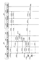
次に、撮影装置150及びストロボ装置160の動作について、図2を用いて説明する。図2は、撮影装置150及びストロボ装置160の動作を示すシーケンス図である。
Next, operations of the image capturing device 150 and the flash device 160 will be described with reference to FIG. FIG. 2 is a sequence diagram illustrating operations of the image capturing device 150 and the strobe device 160.
最初に、撮影制御部103は、撮影枚数としてN枚の設定を受け付けるとともに(ステップST201)、連続撮影の設定を受け付ける(ステップST202)。
First, the shooting control unit 103 receives a setting of N shots as the number of shots (step ST201) and receives a setting for continuous shooting (step ST202).
次に、撮影制御部103は、通信制御部105に対して、連続撮影の設定を受けたことを通知する(ステップST203)。
Next, the imaging control unit 103 notifies the communication control unit 105 that continuous shooting settings have been received (step ST203).
次に、通信制御部105は、ストロボ発光可能なストロボ装置160を探索するための探索信号を生成し、近距離通信部106または指向性通信部107は、探索信号を含む信号を送信する。また、ストロボ装置160の近距離通信部111または指向性通信部112は、探索信号を含む信号を受信し、通信制御部113は、受信した信号から探索信号を抽出する(発光可能閃光体確認)(ステップST204)。この際に、近距離通信部106は、赤外線を用いて探索信号を送信することにより、探索信号は直進性のある信号になる。また、指向性通信部107は、探索信号を指向性送信することができる。これにより、探索信号は、撮影装置150が撮影したい方向に存在するストロボ装置160のみによって受信されるようにすることができる。
Next, the communication control unit 105 generates a search signal for searching for the strobe device 160 that can emit the strobe light, and the short-range communication unit 106 or the directional communication unit 107 transmits a signal including the search signal. Further, the short-range communication unit 111 or the directional communication unit 112 of the strobe device 160 receives a signal including a search signal, and the communication control unit 113 extracts the search signal from the received signal (confirm flashable flasher). (Step ST204). At this time, the short-range communication unit 106 transmits the search signal using infrared rays, so that the search signal becomes a signal having straightness. In addition, the directional communication unit 107 can transmit a search signal in a directional manner. Thus, the search signal can be received only by the flash device 160 that exists in the direction in which the photographing device 150 wants to photograph.
次に、通信制御部113は、抽出した探索信号を閃光制御部114へ出力する(ステップST205)。
Next, communication control section 113 outputs the extracted search signal to flash control section 114 (step ST205).
次に、閃光制御部114は、充電管理部118に対して、ストロボ発光可能か否かを問い合わせる(ステップST206)。
Next, the flash control unit 114 inquires of the charge management unit 118 whether or not strobe light emission is possible (step ST206).
次に、充電管理部118は、閃光制御部114に対して、ストロボ発光可能であることを通知する(ステップST207)。
Next, charge management section 118 notifies flash control section 114 that strobe light emission is possible (step ST207).
次に、閃光制御部114は、通信制御部113に対して、ストロボ発光可能であることを通知する(ステップST208)。
Next, the flash control unit 114 notifies the communication control unit 113 that strobe light emission is possible (step ST208).
次に、通信制御部113は、ストロボ発光可能であることを撮影装置150に通知するために、ストロボ装置160のIDを含むACK信号を生成し、近距離通信部111または指向性通信部112は、ACK信号を含む信号を送信するとともに、撮影装置150の近距離通信部106または指向性通信部107は、ACK信号を含む信号を受信し、通信制御部105は、受信した信号からACK信号を抽出する(閃光可能通知)(ステップST209)。
Next, the communication control unit 113 generates an ACK signal including the ID of the strobe device 160 in order to notify the photographing device 150 that the strobe light can be emitted, and the short-range communication unit 111 or the directional communication unit 112 , A signal including an ACK signal is transmitted, and the short-range communication unit 106 or the directivity communication unit 107 of the imaging device 150 receives the signal including the ACK signal, and the communication control unit 105 receives the ACK signal from the received signal. Extraction (flash notification) (step ST209).
次に、通信制御部105は、抽出したACK信号を撮影制御部103へ出力する(ステップST210)。
Next, communication control section 105 outputs the extracted ACK signal to imaging control section 103 (step ST210).
次に、撮影制御部103は、LEDを点灯する等により、撮影が可能であることを報知する。
Next, the photographing control unit 103 notifies that photographing is possible, for example, by turning on an LED.
次に、撮影制御部103は、取得したACK信号を閃光体管理部101へ転送する(ステップST211)。
Next, the imaging control unit 103 transfers the acquired ACK signal to the flash body management unit 101 (step ST211).
次に、閃光体管理部101は、取得したACK信号に含まれるIDを抽出する。また、閃光体管理部101は、撮影部104のシャッターが操作されたことを検出した際に、通信制御部105に対して、抽出したIDを出力するとともに発光指示信号を生成することを指示する(ステップST212)。閃光体管理部101は、複数のACK信号が入力した際には、最初に入力したACK信号に含まれるIDのストロボ装置160に対する発光指示信号の生成を指示する。
Next, the flash body management unit 101 extracts the ID included in the acquired ACK signal. Further, when the flash body management unit 101 detects that the shutter of the photographing unit 104 has been operated, it instructs the communication control unit 105 to output the extracted ID and generate a light emission instruction signal. (Step ST212). When a plurality of ACK signals are input, the flash body management unit 101 instructs generation of a light emission instruction signal to the strobe device 160 having the ID included in the first input ACK signal.
次に、通信制御部105は、発光指示信号を生成し、近距離通信部106または指向性通信部107は、発光指示信号を含む信号を送信する。また、ストロボ装置160の近距離通信部111または指向性通信部112は、発光指示信号を含む信号を受信し、通信制御部113は、受信した信号から発光指示信号を抽出する(発光指示)(ステップST213)。
Next, the communication control unit 105 generates a light emission instruction signal, and the short-range communication unit 106 or the directivity communication unit 107 transmits a signal including the light emission instruction signal. The short-range communication unit 111 or the directional communication unit 112 of the strobe device 160 receives a signal including a light emission instruction signal, and the communication control unit 113 extracts a light emission instruction signal from the received signal (light emission instruction) ( Step ST213).
次に、通信制御部113は、抽出した発光指示信号を閃光制御部114へ出力する(ステップST214)。
Next, communication control section 113 outputs the extracted light emission instruction signal to flash control section 114 (step ST214).
次に、閃光制御部114は、充電管理部118に対して、ストロボ発光可能か否かを問い合わせる(ステップST215)。
Next, the flash control unit 114 inquires of the charge management unit 118 whether or not strobe light emission is possible (step ST215).
次に、充電管理部118は、バッテリ116の電源電圧値がしきい値以上で且つコンデンサ117の充電電圧値がしきい値以上である場合に、閃光制御部114に対してストロボ発光が可能であることを回答する(ステップST216)。
Next, when the power supply voltage value of the battery 116 is equal to or higher than the threshold value and the charging voltage value of the capacitor 117 is equal to or higher than the threshold value, the charge management unit 118 can perform strobe light emission on the flash control unit 114. A certain answer is given (step ST216).
次に、閃光制御部114は、閃光部115に対してストロボ発光を指示し(ステップST217)、閃光部115はストロボ発光する。
Next, the flash control unit 114 instructs the flash unit 115 to emit strobe light (step ST217), and the flash unit 115 performs strobe light emission.
このストロボ発光と同時に、撮影制御部103は、撮影を行う(ステップST218)。
Simultaneously with the flash emission, the imaging control unit 103 performs imaging (step ST218).
次に、撮影制御部103は、ステップST203で通知した時刻からの経過時間をタイマ102のタイマ値を用いて監視し、経過時間が所定時間Δtになった際に、通信制御部105に対してタイムアップを通知する(ステップST219)。その後、タイマ102は、タイマ値をリセットする。
Next, the imaging control unit 103 monitors the elapsed time from the time notified in step ST203 using the timer value of the timer 102, and when the elapsed time reaches a predetermined time Δt, the imaging control unit 103 Time-up is notified (step ST219). Thereafter, the timer 102 resets the timer value.
次に、通信制御部105は、ストロボ発光可能なストロボ装置160を探索するための探索信号を生成し、近距離通信部106または指向性通信部107は、探索信号を含む信号を送信する。また、ストロボ装置160の近距離通信部111または指向性通信部112は、探索信号を含む信号を受信し、通信制御部113は、受信した信号から探索信号を抽出する(発光可能閃光体確認)(ステップST220)。
Next, the communication control unit 105 generates a search signal for searching for the strobe device 160 that can emit the strobe light, and the short-range communication unit 106 or the directional communication unit 107 transmits a signal including the search signal. Further, the short-range communication unit 111 or the directional communication unit 112 of the strobe device 160 receives a signal including a search signal, and the communication control unit 113 extracts the search signal from the received signal (confirm flashable flasher). (Step ST220).
次に、通信制御部113は、抽出した探索信号を閃光制御部114へ出力する(ステップST221)。
Next, communication control section 113 outputs the extracted search signal to flash control section 114 (step ST221).
次に、閃光制御部114は、充電管理部118に対して、ストロボ発光可能か否かを問い合わせる(ステップST222)。
Next, the flash control unit 114 inquires of the charge management unit 118 whether or not strobe light emission is possible (step ST222).
次に、充電管理部118は、閃光制御部114に対して、ストロボ発光可能であることを通知する(ステップST223)。
Next, charge management section 118 notifies flash control section 114 that strobe light emission is possible (step ST223).
次に、閃光制御部114は、通信制御部113に対して、ストロボ発光可能であることを通知する(ステップST224)。
Next, the flash control unit 114 notifies the communication control unit 113 that strobe light emission is possible (step ST224).
次に、通信制御部113は、ストロボ発光可能であることを撮影装置150に通知するために、ストロボ装置160のIDを含むACK信号を生成し、近距離通信部111または指向性通信部112は、ACK信号を含む信号を送信する。また、撮影装置150の近距離通信部106または指向性通信部107は、ACK信号を含む信号を受信し、通信制御部105は、受信した信号からACK信号を抽出する(閃光可能通知)(ステップST225)。
Next, the communication control unit 113 generates an ACK signal including the ID of the strobe device 160 in order to notify the photographing device 150 that the strobe light can be emitted, and the short-range communication unit 111 or the directional communication unit 112 , A signal including an ACK signal is transmitted. In addition, the short-range communication unit 106 or the directional communication unit 107 of the imaging apparatus 150 receives a signal including an ACK signal, and the communication control unit 105 extracts an ACK signal from the received signal (flashable notification) (step) ST225).
次に、通信制御部105は、抽出したACK信号を撮影制御部103へ出力する(ステップST226)。この際、撮影制御部105は、ステップST226による通知があるまで待機している。
Next, communication control section 105 outputs the extracted ACK signal to imaging control section 103 (step ST226). At this time, the imaging control unit 105 stands by until notified by step ST226.
次に、撮影制御部103は、LEDを点灯する等により、撮影が可能であることを報知する。
Next, the photographing control unit 103 notifies that photographing is possible, for example, by turning on an LED.
次に、撮影制御部103は、取得したACK信号を閃光体管理部101へ転送する(ステップST227)。
Next, the imaging control unit 103 transfers the acquired ACK signal to the flash body management unit 101 (step ST227).
次に、閃光体管理部101は、取得したACK信号に含まれるIDを抽出し、通信制御部105に対して、抽出したIDを出力するとともに発光指示信号を生成することを指示する(ステップST228)。閃光体管理部101は、複数のACK信号が入力した際には、最初に入力したACK信号に含まれるIDのストロボ装置160に対する発光指示信号の生成を指示する。
Next, the flash body management unit 101 extracts the ID included in the acquired ACK signal, and instructs the communication control unit 105 to output the extracted ID and generate a light emission instruction signal (step ST228). ). When a plurality of ACK signals are input, the flash body management unit 101 instructs generation of a light emission instruction signal to the strobe device 160 having the ID included in the first input ACK signal.
次に、通信制御部105は、発光指示信号を生成し、近距離通信部106または指向性通信部107は、発光指示信号を含む信号を送信する。また、ストロボ装置160の近距離通信部111または指向性通信部112は、発光指示信号を含む信号を受信し、通信制御部113は、受信した信号から発光指示信号を抽出する(発光指示)(ステップST229)。
Next, the communication control unit 105 generates a light emission instruction signal, and the short-range communication unit 106 or the directivity communication unit 107 transmits a signal including the light emission instruction signal. The short-range communication unit 111 or the directional communication unit 112 of the strobe device 160 receives a signal including a light emission instruction signal, and the communication control unit 113 extracts a light emission instruction signal from the received signal (light emission instruction) ( Step ST229).
次に、通信制御部113は、抽出した発光指示信号を閃光制御部114へ出力する(ステップST230)。
Next, communication control section 113 outputs the extracted light emission instruction signal to flash control section 114 (step ST230).
次に、閃光制御部114は、充電管理部118に対して、ストロボ発光可能か否かを問い合わせる(ステップST231)。
Next, the flash control unit 114 inquires of the charge management unit 118 whether or not strobe light emission is possible (step ST231).
次に、充電管理部118は、バッテリ116の電源電圧値がしきい値以上で且つコンデンサ117の充電電圧値がしきい値以上である場合に、閃光制御部114に対してストロボ発光が可能であることを回答する(ステップST232)。
Next, when the power supply voltage value of the battery 116 is equal to or higher than the threshold value and the charging voltage value of the capacitor 117 is equal to or higher than the threshold value, the charge management unit 118 can perform strobe light emission on the flash control unit 114. A certain answer is given (step ST232).
次に、閃光制御部114は、閃光部115に対してストロボ発光を指示し(ステップST233)、閃光部115はストロボ発光する。
Next, the flash control unit 114 instructs the flash unit 115 to emit strobe light (step ST233), and the flash unit 115 performs strobe light emission.
このストロボ発光と同時に、撮影制御部103は、撮影を行う(ステップST234)。
Simultaneously with the flash emission, the imaging control unit 103 performs imaging (step ST234).
次に、撮影制御部103は、ステップST203で通知した時刻からの経過時間をタイマ102のタイマ値を用いて監視し、経過時間が所定時間Δtになった際に、通信制御部105に対して通知する(ステップST235)。その後、タイマ102は、タイマ値をリセットする。
Next, the imaging control unit 103 monitors the elapsed time from the time notified in step ST203 using the timer value of the timer 102, and when the elapsed time reaches a predetermined time Δt, the imaging control unit 103 Notification is made (step ST235). Thereafter, the timer 102 resets the timer value.
そして、撮影装置150及びストロボ装置160は、ステップST201で受け付けたN枚の撮影が終了するまで、ステップST203〜ステップST218と同様の処理を繰り返す。
The photographing apparatus 150 and the strobe device 160 repeat the same processing as in steps ST203 to ST218 until the N photographings accepted in step ST201 are completed.
撮影制御部103がステップST203、ステップST219及びステップST235で通知したタイミングが各撮影のタイミングであるが、実際には、撮影制御部103は、ストロボ装置160からACK信号を受け取るまで撮影しないように撮影部104を制御する。また、撮影装置150は、1サイクル処理#250、#260毎に1枚ずつ撮影を行うとともに、ストロボ発光可能な複数のストロボ装置160は、1サイクル処理#250、#260毎に各々1回ずつストロボ発光する。
The timing notified by the shooting control unit 103 in step ST203, step ST219, and step ST235 is the timing of each shooting, but actually, the shooting control unit 103 does not shoot until receiving an ACK signal from the strobe device 160. The unit 104 is controlled. In addition, the image capturing apparatus 150 captures one image for each cycle processing # 250 and # 260, and the plurality of strobe devices 160 capable of flash emission once each for each cycle processing # 250 and # 260. The flash fires.
図3は、ストロボ発光可能なストロボ装置160−1〜160−4が順次ストロボ発光する様子を示す図である。図3の場合、被写体である新郎新婦が撮影位置#301を通過する際には、撮影装置150は、赤外線通信を用いて探索信号を送信するか、または探索信号を指向性送信することにより、ストロボ装置160−1のみに探索信号を送信する。この結果、撮影装置150は、ストロボ装置160−1のみからACK信号を受信する。これにより、撮影位置#301において、ストロボ装置160−1は、撮影装置150が撮影する際にストロボ発光する。また、新郎新婦が撮影位置#302を通過した後に撮影位置#503に戻ることにより、撮影装置150は、ストロボ装置160−2のみに探索信号を送信する。この結果、撮影装置150は、ストロボ装置160−2のみからACK信号を2回受信する。これにより、撮影位置#302及び撮影位置#303において、ストロボ装置160−2は、撮影装置150が2回撮影する際に各々ストロボ発光する。また、被写体である新郎新婦が撮影位置#304を通過する際には、撮影装置150は、ストロボ装置160−3のみに探索信号を送信する。この結果、撮影装置150は、ストロボ装置160−3のみからACK信号を受信する。これにより、撮影位置#304において、ストロボ装置160−3は、撮影装置150が撮影する際にストロボ発光する。また、被写体である新郎新婦が撮影位置#305を通過する際には、撮影装置150は、ストロボ装置160−4のみに探索信号を送信する。この結果、撮影装置150は、ストロボ装置160−4のみからACK信号を受信する。これにより、撮影位置#305において、ストロボ装置160−4は、撮影装置150が撮影する際にストロボ発光する。
FIG. 3 is a diagram illustrating a state in which the strobe devices 160-1 to 160-4 capable of strobe emission sequentially emit strobe light. In the case of FIG. 3, when the bride and groom as the subject pass the photographing position # 301, the photographing device 150 transmits the search signal using infrared communication or transmits the search signal in a directional manner. A search signal is transmitted only to the flash device 160-1. As a result, the imaging device 150 receives an ACK signal only from the flash device 160-1. Thus, at the shooting position # 301, the flash device 160-1 emits strobe light when the shooting device 150 performs shooting. Further, when the bride and groom pass the shooting position # 302 and then return to the shooting position # 503, the shooting apparatus 150 transmits a search signal only to the flash device 160-2. As a result, the photographing apparatus 150 receives the ACK signal twice only from the flash device 160-2. Thus, at the shooting position # 302 and the shooting position # 303, the strobe device 160-2 emits strobe light when the shooting device 150 takes a picture twice. Further, when the bride and groom as the subject pass the photographing position # 304, the photographing device 150 transmits a search signal only to the flash device 160-3. As a result, the imaging device 150 receives an ACK signal only from the flash device 160-3. Thus, at the shooting position # 304, the flash device 160-3 emits strobe light when the shooting device 150 takes a picture. Further, when the bride and groom as the subject pass the photographing position # 305, the photographing device 150 transmits a search signal only to the flash device 160-4. As a result, the imaging device 150 receives an ACK signal only from the flash device 160-4. Thus, at the shooting position # 305, the flash device 160-4 emits strobe light when the shooting device 150 performs shooting.
このように、本実施の形態によれば、ストロボ発光可能な複数のストロボ装置を探索するとともに、探索により検出したストロボ装置を順次ストロボ発光させることにより、暗所でも連続撮影を可能にすることができる。
As described above, according to the present embodiment, it is possible to search for a plurality of strobe devices that can emit strobe light, and to sequentially emit strobe light from the strobe devices detected by the search, thereby enabling continuous shooting even in a dark place. it can.
(実施の形態2)
図4は、本発明の実施の形態2に係る撮影システム400の構成を示すブロック図である。
(Embodiment 2)
FIG. 4 is a block diagram showing the configuration of the imaging system 400 according to Embodiment 2 of the present invention.
図4に示す撮影システム400は、図1に示す実施の形態1に係る撮影システム100に対して、撮影装置150の代わりに撮影装置450を有する。なお、図4において、図1と同一構成である部分には同一の符号を付してその説明を省略する。
An imaging system 400 illustrated in FIG. 4 includes an imaging device 450 instead of the imaging device 150 with respect to the imaging system 100 according to Embodiment 1 illustrated in FIG. In FIG. 4, parts having the same configuration as in FIG.
撮影システム400は、撮影装置450及びストロボ装置160を含む。本実施の形態において、撮影装置450及びストロボ装置160は、何れも携帯電話等の通信端末装置である。なお、撮影装置450及びストロボ装置160は、通信端末装置である場合に限らず、任意の装置にすることができる。また、撮影システム400において、ストロボ装置160は、1つに限らず複数存在する場合もあるが、図4では説明の都合上、ストロボ装置160を1つだけ記載し、他のストロボ装置の記載は省略する。
The photographing system 400 includes a photographing device 450 and a strobe device 160. In the present embodiment, the photographing device 450 and the flash device 160 are both communication terminal devices such as mobile phones. Note that the photographing device 450 and the flash device 160 are not limited to communication terminal devices, and can be arbitrary devices. In the photographing system 400, there may be a plurality of strobe devices 160 instead of one. However, in FIG. 4, only one strobe device 160 is shown for convenience of explanation, and other strobe devices are not shown. Omitted.
撮影装置450の構成について、図4を用いて説明する。
The configuration of the imaging device 450 will be described with reference to FIG.
発光タイミング決定手段としてのシナリオ生成部401は、あらかじめ設定した撮影枚数と閃光体管理部402から入力したストロボ装置160の数とに基づいて、各ストロボ装置160のストロボ発光のタイミングを決定する。そして、シナリオ生成部401は、決定したストロボ発光のタイミングの情報である発光タイミング情報を生成して、生成した発光タイミング情報を閃光体管理部402へ出力する。なお、ストロボ発光のタイミングを決定する方法については後述する。
The scenario generation unit 401 serving as the light emission timing determination unit determines the flash emission timing of each flash device 160 based on the preset number of shots and the number of flash devices 160 input from the flash body management unit 402. Then, the scenario generation unit 401 generates light emission timing information that is information on the determined strobe light emission timing, and outputs the generated light emission timing information to the flash body management unit 402. A method for determining the timing of flash emission will be described later.
閃光体管理部402は、通信制御部406から入力した、ストロボ装置160から送信されたACK信号に含まれる、ストロボ装置160固有のIDの種別の数を計測することにより、ストロボ発光可能なストロボ装置160の数を求める。そして、閃光体管理部402は、求めたストロボ装置160の数をシナリオ生成部401へ出力する。また、閃光体管理部402は、シナリオ生成部401から発光タイミング情報が入力した際に、撮影制御部404に対して、発光タイミング情報が生成されたことを通知する。また、閃光体管理部402は、シャッターが操作された検出結果が撮影制御部404から入力した場合で、且つタイマ403のタイマ値が発光タイミング情報のタイミングになった場合に、通信制御部406に対して、ストロボ発光を指示する発光指示信号の生成を要求する。
The flash body management unit 402 measures the number of ID types unique to the flash device 160 included in the ACK signal transmitted from the flash device 160, which is input from the communication control unit 406. The number of 160 is obtained. Then, the flash body management unit 402 outputs the obtained number of strobe devices 160 to the scenario generation unit 401. In addition, when the light emission timing information is input from the scenario generation unit 401, the flash body management unit 402 notifies the imaging control unit 404 that the light emission timing information has been generated. In addition, the flash management unit 402 sends a communication control unit 406 to the communication control unit 406 when the detection result of operating the shutter is input from the imaging control unit 404 and the timer value of the timer 403 reaches the timing of the light emission timing information. On the other hand, generation of a light emission instruction signal for instructing strobe light emission is requested.
タイマ403は、タイマ値をカウントアップする。また、タイマ403は、リセットの指示を受けてタイマ値をリセットする。
The timer 403 counts up the timer value. In addition, the timer 403 resets the timer value in response to a reset instruction.
撮影制御部404は、閃光体管理部402から発光タイミング情報が生成されたことの通知を受けた際に、LEDを点灯する等により撮影が可能であることを報知する。また、撮影制御部404は、撮影部405に設けた撮影のためのシャッターの操作を検出し、検出結果を閃光体管理部402へ出力する。
When the shooting control unit 404 receives a notification that the light emission timing information has been generated from the flash body management unit 402, the shooting control unit 404 notifies that shooting is possible by turning on an LED or the like. Further, the photographing control unit 404 detects an operation of a shutter for photographing provided in the photographing unit 405 and outputs the detection result to the flash body management unit 402.
撮影部405は、撮影のためのシャッターを有する。また、撮影部405は、シャッターの押圧等のシャッターが操作された際に撮影を行う。
The photographing unit 405 has a shutter for photographing. The photographing unit 405 performs photographing when a shutter such as pressing of the shutter is operated.
通信制御部406は、ストロボ装置160を探索するための探索信号を生成する。例えば、通信制御部406は、電話帳情報に登録されているストロボ装置160、または撮影前にIrDA等を用いて一対一通信を行うことによりあらかじめ認識して記憶しておいたストロボ装置160を、探索信号の宛先に設定することができる。また、通信制御部406は、閃光体管理部402からの指示により発光指示信号を生成する。そして、通信制御部406は、設定されている通信方式に応じて近距離通信部407または指向性通信部408を選択し、選択した近距離通信部407または指向性通信部408へ探索信号または発光指示信号を出力する。また、通信制御部406は、近距離通信部407または指向性通信部408から入力した信号からACK信号を抽出し、抽出したACK信号を閃光体管理部402へ出力する。
The communication control unit 406 generates a search signal for searching for the flash device 160. For example, the communication control unit 406 stores the strobe device 160 registered in the phone book information or the strobe device 160 that has been recognized and stored in advance by performing one-to-one communication using IrDA or the like before shooting. It can be set as a search signal destination. In addition, the communication control unit 406 generates a light emission instruction signal according to an instruction from the flash body management unit 402. Then, the communication control unit 406 selects the short-range communication unit 407 or the directional communication unit 408 according to the set communication method, and sends a search signal or light emission to the selected short-range communication unit 407 or directional communication unit 408. An instruction signal is output. Further, the communication control unit 406 extracts an ACK signal from the signal input from the short-range communication unit 407 or the directional communication unit 408, and outputs the extracted ACK signal to the flash body management unit 402.
近距離通信部407は、通信制御部406から入力した発光指示信号または探索信号を、近距離の無線通信が可能な信号に変換して送信する。また、近距離通信部407は、ストロボ装置160から送信された信号を受信し、受信した信号を通信制御部406で処理可能な信号に変換して通信制御部406へ出力する。
The short-range communication unit 407 converts the light emission instruction signal or the search signal input from the communication control unit 406 into a signal capable of short-range wireless communication and transmits the signal. The short-range communication unit 407 receives the signal transmitted from the strobe device 160, converts the received signal into a signal that can be processed by the communication control unit 406, and outputs the signal to the communication control unit 406.
指向性通信部408は、通信制御部406から入力した発光指示信号または探索信号を、赤外線信号等の指向性を有する信号に変換して送信する。また、指向性通信部408は、ストロボ装置160から送信されたACK信号を受信し、受信したACK信号を通信制御部406で処理可能な信号に変換して通信制御部406へ出力する。
The directivity communication unit 408 converts the light emission instruction signal or the search signal input from the communication control unit 406 into a signal having directivity such as an infrared signal and transmits the converted signal. Directivity communication unit 408 receives the ACK signal transmitted from strobe device 160, converts the received ACK signal into a signal that can be processed by communication control unit 406, and outputs the signal to communication control unit 406.
次に、撮影装置450及びストロボ装置160の動作について、図5を用いて説明する。図5は、撮影装置450及びストロボ装置160の動作を示すシーケンス図である。
Next, operations of the image capturing device 450 and the flash device 160 will be described with reference to FIG. FIG. 5 is a sequence diagram showing operations of the image capturing device 450 and the flash device 160.
最初に、撮影制御部404は、連続撮影の設定を受け付ける(ステップST501)。
First, the imaging control unit 404 accepts continuous shooting settings (step ST501).
次に、撮影制御部404は、ステップST501で受け付けた連続撮影する設定を通信制御部406へ通知する(ステップST502)。
Next, photographing control section 404 notifies communication control section 406 of the setting for continuous photographing accepted in step ST501 (step ST502).
次に、通信制御部406は、ストロボ発光可能なストロボ装置を探索するための探索信号を生成し、近距離通信部407または指向性通信部408は、探索信号を含む信号を送信する。また、ストロボ装置160の近距離通信部111または指向性通信部112は、探索信号を含む信号を受信し、通信制御部113は、受信した信号から探索信号を抽出する(発光可能閃光体確認)(ステップST503)。
Next, the communication control unit 406 generates a search signal for searching for a strobe device that can emit strobe light, and the short-range communication unit 407 or the directional communication unit 408 transmits a signal including the search signal. Further, the short-range communication unit 111 or the directional communication unit 112 of the strobe device 160 receives a signal including a search signal, and the communication control unit 113 extracts the search signal from the received signal (confirm flashable flasher). (Step ST503).
次に、通信制御部113は、抽出した探索信号を閃光制御部114へ出力する(ステップST504)。
Next, communication control section 113 outputs the extracted search signal to flash control section 114 (step ST504).
次に、閃光制御部114は、充電管理部118に対して、ストロボ発光可能か否かを問い合わせる(ステップST505)。
Next, the flash control unit 114 inquires of the charge management unit 118 whether or not strobe light emission is possible (step ST505).
次に、充電管理部118は、閃光制御部114に対して、ストロボ発光可能であることを通知する(ステップST506)。
Next, charge management section 118 notifies flash control section 114 that strobe light emission is possible (step ST506).
次に、閃光制御部114は、通信制御部113に対して、ストロボ発光可能であることを通知する(ステップST507)。
Next, the flash control unit 114 notifies the communication control unit 113 that strobe light emission is possible (step ST507).
次に、通信制御部113は、ストロボ発光可能であることを撮影装置450に通知するために、ストロボ装置160のIDを含むACK信号を生成し、近距離通信部111または指向性通信部112は、ACK信号を含む信号を送信する。また、撮影装置450の近距離通信部407または指向性通信部408は、ACK信号を含む信号を受信し、通信制御部406は、受信した信号からACK信号を抽出する(閃光可能通知)(ステップST508)。
Next, the communication control unit 113 generates an ACK signal including the ID of the strobe device 160 in order to notify the photographing device 450 that the strobe light can be emitted, and the short-range communication unit 111 or the directional communication unit 112 , A signal including an ACK signal is transmitted. In addition, the short-range communication unit 407 or the directional communication unit 408 of the imaging device 450 receives a signal including an ACK signal, and the communication control unit 406 extracts an ACK signal from the received signal (flashable notification) (step) ST508).
次に、通信制御部406は、抽出したACK信号を閃光体管理部402へ出力する(ステップST509)。図6(a)は、ストロボ装置160−1〜160−3がACK信号#601〜#603を送信する様子を示す図である。図6(a)の場合、ストロボ装置160−1〜160−3は、3台である。
Next, communication control section 406 outputs the extracted ACK signal to flash body management section 402 (step ST509). FIG. 6A is a diagram illustrating a state in which the flash devices 160-1 to 160-3 transmit ACK signals # 601 to # 603. In the case of FIG. 6A, there are three strobe devices 160-1 to 160-3.
次に、閃光体管理部402は、通信制御部406から取得したACK信号に含まれるIDの種別の数を計測してストロボ装置160の数を求める。
Next, the flash body management unit 402 calculates the number of strobe devices 160 by measuring the number of ID types included in the ACK signal acquired from the communication control unit 406.
次に、閃光体管理部402は、求めた閃光体となり得る通信相手の数(M台)をシナリオ生成部401へ出力する(ステップST510)。
Next, the flash body management unit 402 outputs the number of communication partners (M units) that can be obtained flash bodies to the scenario generation unit 401 (step ST510).
次に、撮影装置450の撮影制御部404は、撮影枚数(N枚)の設定を受け付ける(ステップST511)。
Next, the imaging control unit 404 of the imaging device 450 accepts the setting of the number of captured images (N) (step ST511).
次に、撮影制御部404は、受け付けた撮影枚数のN枚を閃光体管理部402へ通知し(シナリオ生成要求)(ステップST512)、閃光体管理部402は、通知を受けた撮影枚数のN枚をシナリオ生成部401へ通知する(ステップST513)。
Next, the imaging control unit 404 notifies the flash body management unit 402 of the received number of captured images (scenario generation request) (step ST512), and the flash body management unit 402 receives the notified number of captured N images. The sheets are notified to the scenario generation unit 401 (step ST513).
次に、シナリオ生成部401は、ステップST510で取得したストロボ装置160の数(M台)及び、ステップST510で取得した撮影枚数(N枚)に基づいて、各ストロボ装置160のストロボ発光のタイミングを決定する(シナリオ生成)(ステップST514)。例えば、シナリオ生成部401は、撮影時間が3000msec、ストロボ発光可能なストロボ装置160が3台及び撮影枚数が3枚の場合、各ストロボ装置160が1000msec間隔で順次ストロボ発光するタイミングを決定する。
Next, the scenario generation unit 401 determines the flash emission timing of each strobe device 160 based on the number (M) of strobe devices 160 acquired in step ST510 and the number of shots (N) acquired in step ST510. Determine (scenario generation) (step ST514). For example, when the shooting time is 3000 msec, the number of flash devices 160 capable of flash emission is three, and the number of shots is three, the scenario generation unit 401 determines the timing at which each flash device 160 sequentially emits strobe light at intervals of 1000 msec.
次に、シナリオ生成部401は、決定したストロボ発光のタイミングの情報である発光タイミング情報を閃光体管理部402へ出力する(ステップST515)。
Next, the scenario generation unit 401 outputs light emission timing information, which is information on the determined strobe light emission timing, to the flash body management unit 402 (step ST515).
次に、閃光体管理部402は、発光タイミング情報を受け取った際に、撮影制御部404に対して、発光タイミング情報が生成されたことを通知する(生成完了通知)(ステップST516)。
Next, when receiving the light emission timing information, the flash body management unit 402 notifies the imaging control unit 404 that the light emission timing information has been generated (generation completion notification) (step ST516).
次に、撮影制御部404は、LEDを点灯する等により、撮影が可能であることを報知する。
Next, the shooting control unit 404 notifies that shooting is possible, for example, by turning on an LED.
次に、撮影制御部404は、撮影部405のシャッターが操作されたことを検出した際に(ステップST517)、閃光体管理部402に対して、シャッターが操作された検出結果を出力する(シナリオ起動要求)(ステップST518)。
Next, when the shooting control unit 404 detects that the shutter of the shooting unit 405 has been operated (step ST517), the shooting control unit 404 outputs the detection result of the shutter operation to the flash management unit 402 (scenario). Start request) (step ST518).
次に、閃光体管理部402は、通信制御部406に対して、発光指示信号の生成を指示する(発光指示)(ステップST519)。
Next, the flash body management unit 402 instructs the communication control unit 406 to generate a light emission instruction signal (light emission instruction) (step ST519).
次に、通信制御部406は、撮影制御部404に対して、撮影を指示する(ステップST520)。
Next, the communication control unit 406 instructs the shooting control unit 404 to perform shooting (step ST520).
また、通信制御部406は、発光指示信号を生成し、近距離通信部407または指向性通信部408は、発光指示信号を含む信号を送信する。また、ストロボ装置160の近距離通信部111または指向性通信部112は、発光指示信号を含む信号を受信し、通信制御部113は、受信した信号から発光指示信号を抽出する(発光指示)(ステップST521)。
Further, the communication control unit 406 generates a light emission instruction signal, and the short-range communication unit 407 or the directivity communication unit 408 transmits a signal including the light emission instruction signal. The short-range communication unit 111 or the directional communication unit 112 of the strobe device 160 receives a signal including a light emission instruction signal, and the communication control unit 113 extracts a light emission instruction signal from the received signal (light emission instruction) ( Step ST521).
次に、通信制御部113は、抽出した発光指示信号を閃光制御部114へ出力する(ステップST522)。
Next, communication control section 113 outputs the extracted light emission instruction signal to flash control section 114 (step ST522).
次に、閃光制御部114は、充電管理部118に対して、ストロボ発光可能か否かを問い合わせる(ステップST523)。
Next, the flash control unit 114 inquires of the charge management unit 118 whether or not strobe light emission is possible (step ST523).
次に、充電管理部118は、バッテリ116の電源電圧値がしきい値以上で且つコンデンサ117の充電電圧値がしきい値以上である場合に、閃光制御部114に対してストロボ発光が可能であることを回答する(ステップST524)。
Next, when the power supply voltage value of the battery 116 is equal to or higher than the threshold value and the charging voltage value of the capacitor 117 is equal to or higher than the threshold value, the charge management unit 118 can perform strobe light emission on the flash control unit 114. It is answered (step ST524).
次に、閃光制御部114は、閃光部115に対してストロボ発光を指示し(ステップST525)、閃光部115はストロボ発光する。
Next, the flash control unit 114 instructs the flash unit 115 to emit strobe light (step ST525), and the flash unit 115 emits strobe light.
このストロボ発光と同時に、撮影制御部404は、ステップST520での撮影の指示に従って、撮影を行う(ステップST526)。
Simultaneously with the flash emission, the imaging control unit 404 performs imaging in accordance with the imaging instruction in step ST520 (step ST526).
次に、閃光体管理部402は、タイマ403のタイマ値が、次のストロボ装置160にストロボ発光させるタイミングになった際に、通信制御部406に対して、次にストロボ発光するストロボ装置160に送信する発光指示信号の生成を指示する(発光指示)(ステップST527)。
Next, when the timer value of the timer 403 reaches the timing for causing the next strobe device 160 to emit the strobe light, the flash body management unit 402 causes the communication control unit 406 to send the strobe device 160 to which the next strobe light is emitted. An instruction to generate a light emission instruction signal to be transmitted is given (light emission instruction) (step ST527).
次に、通信制御部406は、撮影制御部404に対して、撮影を指示する(ステップST528)。
Next, communication control section 406 instructs photographing control section 404 to perform photographing (step ST528).
また、通信制御部406は、発光指示信号を生成し、近距離通信部407または指向性通信部408は、ステップST521で発光指示信号を送信したストロボ装置160の次にストロボ発光させるストロボ装置160に対して、発光指示信号を含む信号を送信する(ステップST529)。
Further, the communication control unit 406 generates a light emission instruction signal, and the short-range communication unit 407 or the directivity communication unit 408 causes the strobe device 160 that performs strobe light emission next to the strobe device 160 that transmitted the light emission instruction signal in step ST521. On the other hand, a signal including a light emission instruction signal is transmitted (step ST529).
次に、撮影制御部404は、ステップST528での撮影の指示に従って、ステップST529で送信した発光指示信号に従ってストロボ装置160がストロボ発光するタイミングで、撮影を行う(ステップST530)。
Next, in accordance with the shooting instruction in step ST528, shooting control section 404 performs shooting at the timing at which strobe device 160 emits strobe light in accordance with the light emission instruction signal transmitted in step ST529 (step ST530).
図6(b)は、ストロボ装置160−1〜160−3が順次ストロボ発光する様子を示す図である。例えば、図6(b)の場合、シナリオ生成部101は、ストロボ装置160−1、160−2、160−3の順番に1000msecの間隔でストロボ発光するタイミングを決定する。そして、撮影装置450は、各ストロボ装置160−1〜160−3がストロボ発光するタイミングにおいて、発光指示信号#611、#612、#613の順番で発光指示信号#611〜#613を送信する。これにより、撮影装置450は、暗所において、1000msec間隔で連続撮影することが可能になる。
FIG. 6B is a diagram illustrating a state in which the strobe devices 160-1 to 160-3 sequentially emit strobe light. For example, in the case of FIG. 6B, the scenario generation unit 101 determines the timing of strobe light emission at intervals of 1000 msec in the order of the strobe devices 160-1, 160-2, and 160-3. The photographing apparatus 450 transmits the light emission instruction signals # 611 to # 613 in the order of the light emission instruction signals # 611, # 612, and # 613 at the timing when each of the flash devices 160-1 to 160-3 emits the strobe light. Thereby, the imaging device 450 can continuously capture images at 1000 msec intervals in a dark place.
次に、閃光体管理部402は、N枚の撮影が終了した際に、撮影制御部404に対して、撮影終了を通知する(シナリオ実行完了通知)(ステップST531)。
Next, the flash body management unit 402 notifies the imaging control unit 404 of the end of imaging (scenario execution completion notification) when N images have been captured (step ST531).
図7は、撮影装置450が、シナリオ生成部401で生成した発光タイミング情報により、ストロボ装置160の発光タイミングを制御する様子を示す図である。図7の場合、被写体である新郎新婦は、ストロボ装置160−1〜160−4の前を順番に通過するので、撮影装置450のシナリオ生成部401は、ストロボ装置160−1〜160−4が順番にストロボ発光する発光タイミング情報を生成する。
FIG. 7 is a diagram illustrating a state in which the photographing apparatus 450 controls the light emission timing of the flash device 160 based on the light emission timing information generated by the scenario generation unit 401. In the case of FIG. 7, the bride and groom who are the subjects pass in front of the strobe devices 160-1 to 160-4 in order, so that the scenario generation unit 401 of the photographing device 450 has the strobe devices 160-1 to 160-4. Light emission timing information for generating strobe light in order is generated.
このように、本実施の形態によれば、上記実施の形態1の効果に加えて、複数のストロボ装置のストロボ発光のタイミングになった際に、各々のストロボ装置に対して自動的に発光指示信号を各々送信することにより、撮影の都度、ストロボ発光可能なストロボ装置を探す煩わしさをなくすることができる。
As described above, according to the present embodiment, in addition to the effects of the first embodiment, when the flash emission timing of a plurality of flash devices comes, each flash device is automatically instructed to emit light. By transmitting each signal, it is possible to eliminate the troublesomeness of searching for a strobe device that can emit strobe light every time shooting is performed.
(実施の形態3)
図8は、本発明の実施の形態3に係る撮影システム800の構成を示すブロック図である。
(Embodiment 3)
FIG. 8 is a block diagram showing a configuration of imaging system 800 according to Embodiment 3 of the present invention.
図8に示す撮影システム800は、図4に示す実施の形態2に係る撮影システム400に対して、閃光体管理部402の代わりに閃光体管理部801を有し、撮影制御部404の代わりに撮影制御部802を有し、通信制御部406の代わりに通信制御部803を有し、通信制御部113の代わりに通信制御部811を有し、閃光制御部114の代わりに閃光制御部812を有し、充電管理部118の代わりに充電管理部813を有する。なお、図8において、図4と同一構成である部分には同一の符号を付してその説明を省略する。
An imaging system 800 shown in FIG. 8 has a flash body management unit 801 instead of the flash body management unit 402 in contrast to the imaging system 400 according to the second embodiment shown in FIG. An imaging control unit 802, a communication control unit 803 instead of the communication control unit 406, a communication control unit 811 instead of the communication control unit 113, and a flash control unit 812 instead of the flash control unit 114. And a charge management unit 813 instead of the charge management unit 118. In FIG. 8, parts having the same configuration as in FIG.
撮影システム800は、撮影装置850及びストロボ装置860を含む。本実施の形態において、撮影装置850及びストロボ装置860は、何れも携帯電話等の通信端末装置である。なお、撮影装置850及びストロボ装置860は、通信端末装置である場合に限らず、任意の装置にすることができる。また、撮影システム800において、ストロボ装置860は、1つに限らず複数存在する場合もあるが、図8では説明の都合上、ストロボ装置860を1つだけ記載し、他のストロボ装置の記載は省略する。
The imaging system 800 includes an imaging device 850 and a strobe device 860. In the present embodiment, both the photographing device 850 and the strobe device 860 are communication terminal devices such as mobile phones. Note that the photographing device 850 and the flash device 860 are not limited to communication terminal devices, and can be arbitrary devices. In the photographing system 800, there may be a plurality of strobe devices 860 instead of one, but in FIG. 8, only one strobe device 860 is shown for convenience of explanation, and other strobe devices are described. Omitted.
最初に、撮影装置850の構成について、図8を用いて説明する。
First, the configuration of the photographing apparatus 850 will be described with reference to FIG.
シナリオ生成部401は、あらかじめ設定した撮影枚数と閃光体管理部801から入力したストロボ装置860の数とに基づいて、各ストロボ装置860のストロボ発光のタイミングを決定する。そして、シナリオ生成部401は、決定したストロボ発光のタイミングの情報である発光タイミング情報を生成して、生成した発光タイミング情報を閃光体管理部801へ出力する。
The scenario generation unit 401 determines the flash emission timing of each flash device 860 based on the preset number of shots and the number of flash devices 860 input from the flash body management unit 801. Then, the scenario generation unit 401 generates light emission timing information that is information on the determined strobe light emission timing, and outputs the generated light emission timing information to the flash body management unit 801.
閃光体管理部801は、通信制御部803から入力した、ストロボ装置860から送信されたACK信号に含まれる、通信相手固有のIDの種別の数を計測することにより、ストロボ装置860の数を求める。そして、閃光体管理部801は、求めたストロボ装置860の数をシナリオ生成部401へ出力する。また、閃光体管理部801は、シナリオ生成部401から発光タイミング情報が入力した際に、撮影制御部802に対して、発光タイミング情報が生成されたことを通知する。また、閃光体管理部801は、ストロボ装置860のバッテリ116の電圧値の情報である電圧情報が通信制御部803から入力した際に、電圧情報の電圧値を参照し、閃光部115がストロボ発光するために必要な電圧値に充電されるまでの時間を求める。そして、閃光体管理部801は、発光タイミング情報のタイミングを、求めた時間後にストロボ発光するタイミングに修正する。そして、閃光体管理部801は、撮影制御部802に対して、発光タイミング情報を修正したことを通知する。また、閃光体管理部801は、シャッターが操作された検出結果が撮影制御部802から入力した際に、通信制御部803に対して、ストロボ装置860のストロボ発光を指示する発光指示信号の生成を要求する。
The flash body management unit 801 obtains the number of strobe devices 860 by measuring the number of ID types unique to the communication partner included in the ACK signal transmitted from the strobe device 860 input from the communication control unit 803. . Then, the flash body management unit 801 outputs the obtained number of strobe devices 860 to the scenario generation unit 401. In addition, when the light emission timing information is input from the scenario generation unit 401, the flash body management unit 801 notifies the imaging control unit 802 that the light emission timing information has been generated. Further, the flash body management unit 801 refers to the voltage value of the voltage information when the voltage information, which is the voltage value information of the battery 116 of the strobe device 860, is input from the communication control unit 803, and the flash unit 115 emits the strobe light. The time required to charge the battery to the voltage value necessary for this is obtained. Then, the flash body management unit 801 corrects the timing of the light emission timing information to the timing of strobe light emission after the obtained time. Then, the flash body management unit 801 notifies the imaging control unit 802 that the light emission timing information has been corrected. In addition, the flash management unit 801 generates a light emission instruction signal that instructs the communication control unit 803 to emit the strobe light from the strobe device 860 when the detection result of operating the shutter is input from the imaging control unit 802. Request.
撮影制御部802は、閃光体管理部801から発光タイミング情報が生成されたことの通知を受けた際、または発光タイミング情報を修正した通知を受けた際に、LEDを点灯する等により撮影が可能であることを報知する。また、撮影制御部802は、シャッター操作を検出した際に、閃光体管理部801に対して、ストロボ発光を指示するように要求する。また、撮影制御部802は、撮影部405に設けた撮影のためのシャッターの操作を検出し、検出結果を閃光体管理部801へ出力する。
The shooting control unit 802 can take a picture by turning on an LED or the like when receiving notification that the light emission timing information has been generated from the flash body management unit 801 or when receiving notification that the light emission timing information has been corrected. Notify that. Further, when detecting the shutter operation, the imaging control unit 802 requests the flash body management unit 801 to instruct strobe light emission. In addition, the imaging control unit 802 detects an operation of a shutter for imaging provided in the imaging unit 405 and outputs the detection result to the flash body management unit 801.
通信制御部803は、ストロボ装置860を探索するための探索信号を生成する。例えば、通信制御部803は、電話帳情報に登録されているストロボ装置860、または撮影前にIrDA等を用いて一対一通信を行うことによりあらかじめ認識して記憶しておいたストロボ装置860を、探索信号の宛先に設定することができる。また、通信制御部803は、閃光体管理部801からの指示により発光指示信号を生成する。そして、通信制御部803は、設定されている通信方式に応じて近距離通信部407または指向性通信部408を選択し、選択した近距離通信部407または指向性通信部408へ探索信号または発光指示信号を出力する。また、通信制御部803は、近距離通信部407または指向性通信部408から入力した信号からACK信号または電圧情報を抽出し、抽出したACK信号または電圧情報を閃光体管理部801へ出力する。
The communication control unit 803 generates a search signal for searching for the strobe device 860. For example, the communication control unit 803 recognizes the strobe device 860 registered in the phone book information or the strobe device 860 previously recognized and stored by performing one-to-one communication using IrDA or the like before shooting. It can be set as a search signal destination. Further, the communication control unit 803 generates a light emission instruction signal according to an instruction from the flash body management unit 801. Then, the communication control unit 803 selects the short-range communication unit 407 or the directional communication unit 408 according to the set communication method, and sends a search signal or light emission to the selected short-range communication unit 407 or directional communication unit 408. An instruction signal is output. Further, the communication control unit 803 extracts an ACK signal or voltage information from a signal input from the short-range communication unit 407 or the directional communication unit 408, and outputs the extracted ACK signal or voltage information to the flash body management unit 801.
近距離通信部407は、通信制御部803から入力した発光指示信号または探索信号を、近距離の無線通信が可能な信号に変換して送信する。また、近距離通信部407は、ストロボ装置860から送信された信号を受信し、受信した信号を通信制御部803で処理可能な信号に変換して通信制御部803へ出力する。
The short-range communication unit 407 converts the light emission instruction signal or search signal input from the communication control unit 803 into a signal capable of short-range wireless communication and transmits the signal. The short-range communication unit 407 receives the signal transmitted from the strobe device 860, converts the received signal into a signal that can be processed by the communication control unit 803, and outputs the signal to the communication control unit 803.
指向性通信部408は、通信制御部803から入力した発光指示信号または探索信号を、赤外線信号等の指向性を有する信号に変換して送信する。また、指向性通信部408は、ストロボ装置160から送信されたACK信号を受信し、受信したACK信号を通信制御部803で処理可能な信号に変換して通信制御部803へ出力する。
The directivity communication unit 408 converts the light emission instruction signal or search signal input from the communication control unit 803 into a signal having directivity such as an infrared signal and transmits the converted signal. Directivity communication unit 408 receives the ACK signal transmitted from strobe device 160, converts the received ACK signal into a signal that can be processed by communication control unit 803, and outputs the signal to communication control unit 803.
次に、ストロボ装置860の構成について、図8を用いて説明する。
Next, the configuration of the strobe device 860 will be described with reference to FIG.
近距離通信部111は、撮影装置850から送信された信号を受信し、受信した信号を通信制御部811で処理可能な信号に変換して通信制御部811へ出力する。また、近距離通信部111は、通信制御部811から入力した信号を、近距離の無線通信が可能な信号に変換して送信する。
The short-range communication unit 111 receives a signal transmitted from the imaging device 850, converts the received signal into a signal that can be processed by the communication control unit 811, and outputs the signal to the communication control unit 811. The short-range communication unit 111 converts the signal input from the communication control unit 811 into a signal that enables short-range wireless communication and transmits the signal.
指向性通信部112は、撮影装置850から送信された信号を受信し、受信した信号を通信制御部811で処理可能な信号に変換して通信制御部811へ出力する。また、指向性通信部112は、通信制御部811から入力した信号をIr信号等の指向性を有する信号に変換して送信する。
The directional communication unit 112 receives a signal transmitted from the imaging device 850, converts the received signal into a signal that can be processed by the communication control unit 811, and outputs the signal to the communication control unit 811. The directivity communication unit 112 converts the signal input from the communication control unit 811 into a signal having directivity such as an Ir signal and transmits the signal.
通信制御部811は、近距離通信部111または指向性通信部112から入力した信号から探索信号を抽出した場合に、抽出した探索信号に含まれるアドレスを参照し、受信した探索信号が受信処理すべき信号であるか否かを判定する。また、通信制御部811は、受信処理すべき信号であると判定した場合に、閃光制御部812に対して、ストロボ発光可能か否かを問い合わせる。そして、通信制御部811は、閃光制御部812からストロボ発光可能である回答が得られた場合に、自局のIDを含むACK信号を生成する。また、通信制御部811は、充電管理部813からバッテリ116の電圧値を取得し、取得した電圧値の電圧情報を生成する。そして、通信制御部811は、ACK信号または電圧情報を含む信号を生成する。そして、通信制御部811は、設定されている通信方式に応じて近距離通信部111または指向性通信部112を選択し、選択した近距離通信部111または指向性通信部112へACK信号または電圧情報を含む信号を出力する。また、通信制御部811は、近距離通信部111または指向性通信部112から入力した信号から発光指示信号を抽出した場合に、抽出した発光指示信号を閃光制御部812へ出力する。
When the communication control unit 811 extracts a search signal from the signal input from the short-range communication unit 111 or the directional communication unit 112, the communication control unit 811 refers to the address included in the extracted search signal, and receives the received search signal. It is determined whether the signal is a power signal. If the communication control unit 811 determines that the signal is to be received, the communication control unit 811 inquires of the flash control unit 812 whether or not strobe light emission is possible. The communication control unit 811 generates an ACK signal including the ID of its own station when an answer indicating that the flash control unit 812 can emit the strobe light is obtained. Further, the communication control unit 811 acquires the voltage value of the battery 116 from the charge management unit 813, and generates voltage information of the acquired voltage value. Then, the communication control unit 811 generates an ACK signal or a signal including voltage information. Then, the communication control unit 811 selects the short-range communication unit 111 or the directional communication unit 112 according to the set communication method, and sends an ACK signal or voltage to the selected short-range communication unit 111 or the directional communication unit 112. Output a signal containing information. When the communication control unit 811 extracts a light emission instruction signal from the signal input from the short-range communication unit 111 or the directivity communication unit 112, the communication control unit 811 outputs the extracted light emission instruction signal to the flash control unit 812.
閃光制御部812は、通信制御部811から発光指示信号が入力した際に、ストロボ発光が可能であるか否かを充電管理部813に問い合わせる。そして、閃光制御部812は、充電管理部813からストロボ発光が可能である回答が得られた場合に、閃光部115に対して、ストロボ発光を指示する。一方、閃光制御部812は、充電管理部813からストロボ発光が不可能である回答が得られた場合に、閃光部115に対して、閃光制御部114から新たな発光指示信号が入力するまでストロボ発光を待機させる。
When the flash control unit 812 receives a light emission instruction signal from the communication control unit 811, the flash control unit 812 inquires of the charge management unit 813 whether or not strobe light emission is possible. Then, the flash control unit 812 instructs the flash unit 115 to perform strobe light emission when an answer indicating that strobe light emission is possible is obtained from the charge management unit 813. On the other hand, if the flash control unit 812 receives an answer from the charge management unit 813 that strobe lighting is not possible, the flash control unit 812 receives the strobe until a new flash instruction signal is input from the flash control unit 114 to the flash unit 115. Wait for the flash to fire.
充電管理部813は、バッテリ116の電源電圧値と、コンデンサ117の充電状態を監視する。そして、充電管理部813は、閃光制御部812からストロボ発光が可能であるか否かの問い合わせを受けた際には、バッテリ116の電源電圧値がしきい値以上で且つコンデンサ117の充電電圧値がしきい値以上である場合に、閃光制御部812に対してストロボ発光が可能であることを回答する。一方、充電管理部813は、バッテリ116の電源電圧値がしきい値未満である場合に、バッテリ116の電源電圧値を通信制御部811へ報告する。
The charge management unit 813 monitors the power supply voltage value of the battery 116 and the charge state of the capacitor 117. When the charge management unit 813 receives an inquiry from the flash control unit 812 as to whether or not strobe light emission is possible, the power supply voltage value of the battery 116 is equal to or greater than the threshold value and the charge voltage value of the capacitor 117. Is greater than or equal to the threshold value, the flash control unit 812 is replied that strobe light emission is possible. On the other hand, the charge management unit 813 reports the power supply voltage value of the battery 116 to the communication control unit 811 when the power supply voltage value of the battery 116 is less than the threshold value.
閃光部115は、閃光制御部812の指示に従ってストロボ発光する。
The flash unit 115 emits strobe light according to an instruction from the flash control unit 812.
次に、撮影装置850及びストロボ装置860の動作について、図9を用いて説明する。図9は、撮影装置850及びストロボ装置860の動作を示すシーケンス図である。なお、図9において、図5と同一の動作である部分には同一の符号を付してその説明を省略する。
Next, operations of the photographing apparatus 850 and the strobe device 860 will be described with reference to FIG. FIG. 9 is a sequence diagram showing operations of the image capturing device 850 and the flash device 860. In FIG. 9, parts that are the same as those in FIG. 5 are given the same reference numerals, and descriptions thereof are omitted.
図9より、閃光制御部812は、充電管理部813に対して、ストロボ発光可能か否かを問い合わせる(ステップST523)。
From FIG. 9, the flash control unit 812 inquires of the charge management unit 813 whether or not strobe light emission is possible (step ST523).
次に、充電管理部813は、バッテリ116の電源電圧値を通信制御部811へ報告し、通信制御部811は、電源電圧値を取得する(ステップST901)。
Next, charge management section 813 reports the power supply voltage value of battery 116 to communication control section 811, and communication control section 811 acquires the power supply voltage value (step ST901).
次に、通信制御部811は、電圧情報を生成し、近距離通信部111または指向性通信部112は、電圧情報を含む信号を送信するとともに、撮影装置850の近距離通信部407または指向性通信部408は、電圧情報を含む信号を受信し、通信制御部803は、電圧情報を取得する(ステップST902)。
Next, the communication control unit 811 generates voltage information, and the short-range communication unit 111 or the directivity communication unit 112 transmits a signal including the voltage information, and the short-range communication unit 407 or directivity of the imaging apparatus 850. Communication unit 408 receives a signal including voltage information, and communication control unit 803 acquires voltage information (step ST902).
次に、通信制御部803は、取得した電圧情報を閃光体管理部801へ出力する(ステップST903)。
Next, communication control section 803 outputs the acquired voltage information to flash body management section 801 (step ST903).
次に、閃光体管理部801は、発光タイミング情報のストロボ発光のタイミングを補正する(発光タイミング見直し)(ステップST904)。
Next, the flash body management unit 801 corrects the strobe light emission timing of the light emission timing information (review the light emission timing) (step ST904).
図10は、ストロボ発光のタイミングを補正する方法を示す図である。図10は、例えば、撮影装置850が、ストロボ装置A〜Dを4台検出した場合で、且つストロボ装置Aがストロボ発光してから次にストロボ発光するまでの充電に必要な時間が1secである場合を示している。撮影装置850の閃光体管理部801は、電圧値とストロボ発光するまでに必要な時間とを対応付けた発光タイミング補正情報を記憶している。また、閃光体管理部801は、ストロボ装置Aの電圧情報の電源電圧値を用いて、発光タイミング補正情報を参照することにより、ストロボ装置Aがストロボ発光するまでに必要な時間を求める。そして、閃光体管理部801は、ストロボ装置Aのストロボ発光のタイミングを、求めた時間経過後にストロボ発光するストロボ発光のタイミングに補正する。また、閃光体管理部801は、補正後のストロボ発光のタイミングから1sec間隔でストロボ発光するストロボ発光のタイミングになるようにストロボ装置Aのストロボ発光のタイミングを補正する。また、この補正に合わせて、ストロボ装置B〜ストロボ装置Dが、ストロボ装置Aがストロボ発光してから1sec以内に等間隔でストロボ発光するようにストロボ装置B〜ストロボ装置Dのストロボ発光のタイミングを補正する。
FIG. 10 is a diagram illustrating a method of correcting the flash emission timing. FIG. 10 shows, for example, a case where the photographing device 850 detects four strobe devices A to D and the time required for charging from the strobe device A to strobe light emission until the next strobe light emission is 1 sec. Shows the case. The flash body management unit 801 of the photographing apparatus 850 stores light emission timing correction information in which a voltage value is associated with a time necessary for strobe light emission. In addition, the flash body management unit 801 obtains a time required until the flash device A emits the strobe light by referring to the light emission timing correction information using the power supply voltage value of the voltage information of the strobe device A. Then, the flash body management unit 801 corrects the strobe light emission timing of the strobe device A to the strobe light emission timing at which the strobe light is emitted after the obtained time has elapsed. In addition, the flash body management unit 801 corrects the strobe light emission timing of the strobe device A so that the strobe light emission timing is 1 st interval from the corrected strobe light emission timing. In accordance with this correction, the strobe device B to strobe device D emit the strobe light at equal intervals within 1 sec after the strobe device A fires the strobe light. to correct.
図11は、各閃光体A〜Dの補正後のストロボ発光のタイミングを示す図である。図11より、閃光体A〜閃光体Dのストロボ発光のタイミングは、250msecで順次ストロボ発光するストロボ発光のタイミングに補正される。これにより、ステップST527以降は、補正後のストロボ発光のタイミングで発光指示信号が送信される。
FIG. 11 is a diagram showing the timing of strobe light emission after correction of each flash body A to D. As shown in FIG. From FIG. 11, the flash emission timings of the flash body A to the flash body D are corrected to the flash emission timing at which the flash emission is sequentially performed at 250 msec. Thereby, after step ST527, the light emission instruction signal is transmitted at the corrected strobe light emission timing.
図9に戻って、次に、閃光体管理部801は、通信制御部803に対して、次にストロボ発光させるストロボ装置860に送信するための発光指示信号の生成を指示する(発光指示)(ステップST527)。
Returning to FIG. 9, next, the flash body management unit 801 instructs the communication control unit 803 to generate a light emission instruction signal to be transmitted to the strobe device 860 that performs next strobe light emission (light emission instruction) ( Step ST527).
このように、本実施の形態によれば、上記実施の形態2の効果に加えて、ストロボ装置の電圧情報を参照してストロボ発光のタイミングを補正するので、ストロボ装置を確実にストロボ発光させることができる。
As described above, according to the present embodiment, in addition to the effect of the second embodiment, the strobe light emission timing is corrected by referring to the voltage information of the strobe device, so that the strobe device can reliably emit the strobe light. Can do.
(実施の形態4)
図12は、本発明の実施の形態4に係る撮影システム1200の構成を示すブロック図である。
(Embodiment 4)
FIG. 12 is a block diagram showing a configuration of imaging system 1200 according to Embodiment 4 of the present invention.
図12に示す撮影システム1200は、図4に示す実施の形態2に係る撮影システム400に対して、タイマ1211及びシナリオ実行部1212を追加し、閃光体管理部402の代わりに閃光体管理部1201を有し、閃光制御部114の代わりに閃光制御部1213を有する。なお、図12において、図4と同一構成である部分には同一の符号を付してその説明を省略する。
An imaging system 1200 shown in FIG. 12 adds a timer 1211 and a scenario execution unit 1212 to the imaging system 400 according to the second embodiment shown in FIG. 4, and a flash body management unit 1201 instead of the flash body management unit 402. And a flash control unit 1213 instead of the flash control unit 114. In FIG. 12, parts having the same configuration as in FIG.
撮影システム1200は、撮影装置1250及びストロボ装置1260を含む。本実施の形態において、撮影装置1250及びストロボ装置1260は、何れも携帯電話等の通信端末装置である。なお、撮影装置1250及びストロボ装置1260は、通信端末装置である場合に限らず、任意の装置にすることができる。また、撮影システム1200において、ストロボ装置1260は、1つに限らず複数存在する場合もあるが、図12では説明の都合上、ストロボ装置1260を1つだけ記載し、他のストロボ装置の記載は省略する。
The imaging system 1200 includes an imaging device 1250 and a strobe device 1260. In the present embodiment, the photographing device 1250 and the strobe device 1260 are both communication terminal devices such as mobile phones. Note that the photographing device 1250 and the flash device 1260 are not limited to communication terminal devices, and can be arbitrary devices. Further, in the photographing system 1200, there may be a plurality of strobe devices 1260, but there may be a plurality of strobe devices 1260. However, in FIG. 12, for convenience of explanation, only one strobe device 1260 is described, and other strobe devices are described. Omitted.
最初に、撮影装置1250の構成について、図12を用いて説明する。
First, the configuration of the photographing apparatus 1250 will be described with reference to FIG.
シナリオ生成部401は、あらかじめ設定した撮影枚数と閃光体管理部1201から入力したストロボ装置1260の数とに基づいて、各ストロボ装置1260のストロボ発光のタイミングを決定する。そして、シナリオ生成部401は、決定したストロボ発光のタイミングの情報である発光タイミング情報を生成して、生成した発光タイミング情報を閃光体管理部1201へ出力する。
The scenario generation unit 401 determines the flash emission timing of each flash device 1260 based on the preset number of shots and the number of flash devices 1260 input from the flash body management unit 1201. Then, the scenario generation unit 401 generates light emission timing information that is information on the determined strobe light emission timing, and outputs the generated light emission timing information to the flash body management unit 1201.
閃光体管理部1201は、通信制御部406から入力した、ストロボ装置1260から送信されたACK信号に含まれる、ストロボ装置1260固有のIDの種別の数を計測することにより、ストロボ発光可能なストロボ装置1260の数を求める。そして、閃光体管理部1201は、求めたストロボ装置1260の数をシナリオ生成部401へ出力する。また、閃光体管理部1201は、シナリオ生成部401から発光タイミング情報が入力した際に、撮影制御部404に対して、発光タイミング情報が生成されたことを撮影制御部404へ通知するとともに、発光タイミング情報を通信制御部406へ出力する。また、閃光体管理部1201は、シャッターが操作された検出結果が撮影制御部404から入力した場合で、且つタイマ403のタイマ値が発光タイミング情報の最初のストロボ発光のタイミングになった場合に、撮影を開始することを通知する撮影開始信号を通信制御部406へ出力する。
The flash management unit 1201 measures the number of ID types unique to the strobe device 1260 included in the ACK signal transmitted from the strobe device 1260, which is input from the communication control unit 406. The number of 1260 is obtained. Then, the flash body management unit 1201 outputs the obtained number of strobe devices 1260 to the scenario generation unit 401. Further, when the flash body management unit 1201 receives the light emission timing information from the scenario generation unit 401, the flash body management unit 1201 notifies the shooting control unit 404 that the light emission timing information has been generated, and emits light. Timing information is output to the communication control unit 406. Further, the flash body management unit 1201 receives the detection result of operating the shutter from the imaging control unit 404, and when the timer value of the timer 403 is the first flash emission timing of the emission timing information. A shooting start signal notifying that shooting is started is output to the communication control unit 406.
撮影制御部404は、閃光体管理部1201から発光タイミング情報が生成されたことの通知を受けた際に、LEDを点灯する等により撮影が可能であることを報知する。また、撮影制御部404は、撮影部405に設けた撮影のためのシャッターの操作を検出し、検出結果を閃光体管理部1201へ出力する。
When receiving a notification that the light emission timing information has been generated from the flash body management unit 1201, the shooting control unit 404 notifies that shooting is possible by turning on an LED or the like. In addition, the imaging control unit 404 detects an operation of a shutter for imaging provided in the imaging unit 405 and outputs a detection result to the flash body management unit 1201.
通信制御部406は、ストロボ装置1260を探索するための探索信号を生成する。例えば、通信制御部406は、電話帳情報に登録されているストロボ装置1260、または撮影前にIrDA等を用いて一対一通信を行うことによりあらかじめ認識して記憶しておいたストロボ装置1260を、探索信号の宛先に設定することができる。また、通信制御部406は、設定されている通信方式に応じて近距離通信部407または指向性通信部408を選択し、選択した近距離通信部407または指向性通信部408へ探索信号、発光タイミング情報または撮影開始信号を出力する。この際に、通信制御部406は、探索により検出した全てのストロボ発光可能なストロボ装置1260に対して、発光タイミング情報を同時に送信するタイミングで出力する。また、通信制御部406は、近距離通信部407または指向性通信部408から入力した信号からACK信号を抽出し、抽出したACK信号を閃光体管理部1201へ出力する。
The communication control unit 406 generates a search signal for searching for the strobe device 1260. For example, the communication control unit 406 stores the strobe device 1260 registered in the phone book information or the strobe device 1260 that has been recognized and stored in advance by performing one-to-one communication using IrDA or the like before shooting. It can be set as a search signal destination. Further, the communication control unit 406 selects the short-range communication unit 407 or the directional communication unit 408 according to the set communication method, and sends a search signal and light emission to the selected short-range communication unit 407 or directional communication unit 408. Output timing information or shooting start signal. At this time, the communication control unit 406 outputs the light emission timing information to all the strobe devices 1260 capable of light emission detected by the search at the timing of transmitting simultaneously. Further, the communication control unit 406 extracts an ACK signal from the signal input from the short-range communication unit 407 or the directional communication unit 408 and outputs the extracted ACK signal to the flash body management unit 1201.
次に、ストロボ装置1260の構成について、図12を用いて説明する。
Next, the configuration of the strobe device 1260 will be described with reference to FIG.
通信制御部113は、近距離通信部111または指向性通信部112から入力した信号から探索信号を抽出した場合に、抽出した探索信号に含まれるアドレスを参照し、受信した探索信号が受信処理すべき信号であるか否かを判定する。また、通信制御部113は、受信処理すべき信号であると判定した場合に、閃光制御部1213に対して、ストロボ発光可能か否かを問い合わせる。そして、通信制御部113は、閃光制御部1213からストロボ発光可能である回答が得られた場合に、自局のIDを含むACK信号を生成する。そして、通信制御部113は、ACK信号を含む信号を生成する。また、通信制御部113は、設定されている通信方式に応じて近距離通信部111または指向性通信部112を選択し、選択した近距離通信部111または指向性通信部112へACK信号を含む信号を出力する。また、通信制御部113は、近距離通信部111または指向性通信部112から入力した信号から発光タイミング情報または撮影開始信号を抽出した場合に、抽出した発光タイミング情報または撮影開始信号をシナリオ実行部1212へ出力する。
When the search signal is extracted from the signal input from the short-range communication unit 111 or the directional communication unit 112, the communication control unit 113 refers to the address included in the extracted search signal, and the received search signal performs reception processing. It is determined whether the signal is a power signal. If the communication control unit 113 determines that the signal is to be received, the communication control unit 113 inquires of the flash control unit 1213 whether or not strobe light emission is possible. Then, when an answer indicating that the flash control unit 1213 can emit strobe light is obtained from the flash control unit 1213, the communication control unit 113 generates an ACK signal including the ID of the local station. Then, the communication control unit 113 generates a signal including an ACK signal. Further, the communication control unit 113 selects the short-range communication unit 111 or the directional communication unit 112 according to the set communication method, and includes an ACK signal to the selected short-range communication unit 111 or the directional communication unit 112. Output a signal. Further, when the communication control unit 113 extracts the light emission timing information or the imaging start signal from the signal input from the short-range communication unit 111 or the directivity communication unit 112, the communication execution unit 113 uses the extracted light emission timing information or the imaging start signal as the scenario execution unit. To 1212.
タイマ1211は、タイマ403と同期しており、シナリオ実行部1212の指示により、タイマ値のカウントアップを開始する。また、タイマ1211は、リセットの指示を受けてタイマ値をリセットする。
The timer 1211 is synchronized with the timer 403 and starts counting up the timer value in accordance with an instruction from the scenario execution unit 1212. In addition, the timer 1211 resets the timer value upon receiving a reset instruction.
シナリオ実行部1212は、通信制御部113から撮影開始信号が入力した際に、タイマ1211に対して、タイマ値のカウントアップの開始を指示する。また、シナリオ実行部1212は、通信制御部113から入力した発光タイミング情報を参照し、タイマ1211で計測した計測値が発光タイミング情報のストロボ発光のタイミングになった際に、閃光制御部1213に対してストロボ発光を指示する。
When the shooting start signal is input from the communication control unit 113, the scenario execution unit 1212 instructs the timer 1211 to start counting up the timer value. Also, the scenario execution unit 1212 refers to the light emission timing information input from the communication control unit 113, and when the measured value measured by the timer 1211 becomes the strobe light emission timing of the light emission timing information, the scenario execution unit 1212 Instruct the flash to fire.
閃光制御部1213は、探索信号を取得した通信制御部113から問い合わせを受けた際に、ストロボ発光が可能であるか否かを充電管理部118に問い合わせる。そして、閃光制御部1213は、充電管理部118からストロボ発光が可能である回答が得られた場合に、ストロボ発光が可能であることを通信制御部113に通知する。また、閃光制御部1213は、シナリオ実行部1212からストロボ発光を指示された際に、閃光部115に対して、ストロボ発光を指示する。
When the flash control unit 1213 receives an inquiry from the communication control unit 113 that has acquired the search signal, the flash control unit 1213 inquires of the charge management unit 118 whether or not strobe light emission is possible. Then, the flash control unit 1213 notifies the communication control unit 113 that strobe light emission is possible when an answer indicating that strobe light emission is possible is obtained from the charge management unit 118. Also, the flash control unit 1213 instructs the flash unit 115 to emit strobe light when the scenario execution unit 1212 is instructed to emit strobe light.
充電管理部118は、バッテリ116の電源電圧値と、コンデンサ117の充電状態を監視する。そして、充電管理部118は、閃光制御部1213からストロボ発光が可能であるか否かの問い合わせを受けた際には、バッテリ116の電源電圧値がしきい値以上で且つコンデンサ117の充電電圧値がしきい値以上である場合に、閃光制御部1213に対してストロボ発光が可能であることを回答する。
The charge management unit 118 monitors the power supply voltage value of the battery 116 and the charge state of the capacitor 117. When the charge management unit 118 receives an inquiry from the flash control unit 1213 as to whether or not strobe light emission is possible, the power supply voltage value of the battery 116 is equal to or higher than the threshold value and the charge voltage value of the capacitor 117. Is greater than or equal to the threshold value, the flash control unit 1213 is replied that strobe light emission is possible.
閃光部115は、閃光制御部1213の指示に従ってストロボ発光する。
The flash unit 115 emits strobe light in accordance with an instruction from the flash control unit 1213.
次に、撮影装置1250及びストロボ装置1260の動作について、図13を用いて説明する。図13は、撮影装置1250及びストロボ装置1260の動作を示すシーケンス図である。なお、図13において、図5と同一の動作である部分には同一の符号を付してその説明を省略する。
Next, operations of the photographing apparatus 1250 and the strobe device 1260 will be described with reference to FIG. FIG. 13 is a sequence diagram showing operations of the photographing apparatus 1250 and the strobe device 1260. In FIG. 13, parts that are the same as those in FIG. 5 are given the same reference numerals, and descriptions thereof are omitted.
図13より、閃光体管理部1201は、発光タイミング情報を受け取った際に、撮影制御部404に対して、発光タイミング情報が生成されたことを通知する(生成完了通知)(ステップST516)。
As shown in FIG. 13, when receiving the light emission timing information, the flash body management unit 1201 notifies the imaging control unit 404 that the light emission timing information has been generated (generation completion notification) (step ST516).
次に、撮影制御部404は、LEDを点灯する等により、撮影が可能であることを報知する。
Next, the shooting control unit 404 notifies that shooting is possible, for example, by turning on an LED.
次に、閃光体管理部1201は、発光タイミング情報を通信制御部406へ出力する(ステップST1301)。
Next, the flash body management unit 1201 outputs the light emission timing information to the communication control unit 406 (step ST1301).
また、通信制御部406は、発光タイミング情報を含む信号を生成し、近距離通信部407または指向性通信部408は、発光タイミング情報を含む信号を送信するとともに、近距離通信部111または指向性通信部112は、発光タイミング情報を含む信号を受信し、通信制御部113は、受信した信号から発光タイミング情報を抽出する(ステップST1302)。
Further, the communication control unit 406 generates a signal including the light emission timing information, and the short-range communication unit 407 or the directivity communication unit 408 transmits the signal including the light emission timing information, and the short-range communication unit 111 or the directivity. Communication unit 112 receives a signal including light emission timing information, and communication control unit 113 extracts light emission timing information from the received signal (step ST1302).
次に、通信制御部113は、抽出した発光タイミング情報をシナリオ実行部1212へ出力する(ステップST1303)。
Next, communication control section 113 outputs the extracted light emission timing information to scenario execution section 1212 (step ST1303).
次に、シナリオ実行部1212は、発光タイミング情報を受け取った際に、閃光制御部1213に対して、ストロボ発光が可能か否かを問い合わせる(ステップST1304)。
Next, when the scenario execution unit 1212 receives the light emission timing information, the scenario execution unit 1212 inquires of the flash control unit 1213 whether or not strobe light emission is possible (step ST1304).
次に、閃光制御部1213は、充電管理部118に対して、ストロボ発光可能か否かを問い合わせる(ステップST1305)。
Next, the flash control unit 1213 inquires of the charge management unit 118 whether or not strobe light emission is possible (step ST1305).
次に、充電管理部118は、バッテリ116の電源電圧値がしきい値以上で且つコンデンサ117の充電電圧値がしきい値以上である場合に、閃光制御部1213に対してストロボ発光が可能であることを回答する(ステップST1306)。
Next, when the power supply voltage value of the battery 116 is equal to or greater than the threshold value and the charge voltage value of the capacitor 117 is equal to or greater than the threshold value, the charge management unit 118 can perform strobe light emission with respect to the flash control unit 1213. It is answered (step ST1306).
次に、撮影装置450の閃光体管理部1201は、ステップST1302で発光タイミング情報を送信したストロボ装置1260の次にストロボ発光するストロボ装置1260に送信する発光タイミング情報を通信制御部406へ出力する(ステップST1307)。
Next, the flash body management unit 1201 of the photographing apparatus 450 outputs to the communication control unit 406 the light emission timing information to be transmitted to the strobe device 1260 that emits the strobe light next to the strobe device 1260 that has transmitted the light emission timing information in step ST1302. Step ST1307).
また、通信制御部406は、発光タイミング情報を含む信号を生成し、近距離通信部407または指向性通信部408は、発光タイミング情報を含む信号を送信する(ステップST1308)。このように、撮影装置1250は、ストロボ発光可能な全てのストロボ装置1260に対して、発光タイミング情報を略同時に送信する。
Moreover, the communication control part 406 produces | generates the signal containing light emission timing information, and the short distance communication part 407 or the directional communication part 408 transmits the signal containing light emission timing information (step ST1308). In this way, the photographing apparatus 1250 transmits the light emission timing information to all the strobe devices 1260 capable of strobe light emission substantially simultaneously.
次に、撮影制御部404は、撮影部405のシャッターが操作されたことを検出すると(ステップST1309)、閃光体管理部1201に対して、検出結果を出力する(ステップST1310)。
Next, when the photographing control unit 404 detects that the shutter of the photographing unit 405 has been operated (step ST1309), the photographing control unit 404 outputs a detection result to the flash body management unit 1201 (step ST1310).
次に、閃光体管理部1201は、通信制御部406に対して、撮影開始を通知するための撮影開始信号の生成を指示する(ステップST1311)。
Next, the flash body management unit 1201 instructs the communication control unit 406 to generate a shooting start signal for notifying the start of shooting (step ST1311).
次に、通信制御部406は、撮影制御部404に対して、撮影を指示する(ステップST1312)。
Next, the communication control unit 406 instructs the shooting control unit 404 to perform shooting (step ST1312).
また、通信制御部406は、撮影開始信号を生成し、近距離通信部407または指向性通信部408は、全てのストロボ発光可能なストロボ装置宛に対して撮影開始信号を含む信号を送信するとともに、近距離通信部111または指向性通信部112は、撮影開始信号を含む信号を受信し、通信制御部113は、受信した信号から撮影開始信号を抽出する(ステップST1313)。
In addition, the communication control unit 406 generates a shooting start signal, and the short-range communication unit 407 or the directivity communication unit 408 transmits a signal including the shooting start signal to all strobe devices capable of flash emission. The short-range communication unit 111 or the directivity communication unit 112 receives a signal including a shooting start signal, and the communication control unit 113 extracts a shooting start signal from the received signal (step ST1313).
次に、通信制御部113は、抽出した撮影開始信号をシナリオ実行部1212へ出力する(ステップST1314)。
Next, communication control section 113 outputs the extracted shooting start signal to scenario execution section 1212 (step ST1314).
次に、シナリオ実行部1212は、タイマ1211のタイマ値のカウントアップを開始し、カウントアップしたタイマ値が発光タイミング情報のストロボ発光のタイミングになった際に、閃光制御部1213に対して、ストロボ発光を指示する(ステップST1315)。
Next, the scenario execution unit 1212 starts to count up the timer value of the timer 1211. When the counted timer value becomes the strobe emission timing of the light emission timing information, the scenario execution unit 1212 gives the flash control unit 1213 a strobe light. Light emission is instructed (step ST1315).
次に、閃光制御部1213は、閃光部115に対してストロボ発光を指示し(ステップST1316)、閃光部115はストロボ発光する。
Next, the flash control unit 1213 instructs the flash unit 115 to perform strobe light emission (step ST1316), and the flash unit 115 performs strobe light emission.
このストロボ発光と同時に、撮影制御部404は、ステップST1312での撮影の指示に従って、撮影を行う(ステップST1317)。
Simultaneously with the flash emission, the imaging control unit 404 performs imaging according to the imaging instruction in step ST1312 (step ST1317).
次に、閃光体管理部1201は、撮影制御部404に対して、撮影開始信号の送信が完了したことを通知する(ステップST1318)。
Next, the flash body management unit 1201 notifies the imaging control unit 404 that the transmission of the imaging start signal has been completed (step ST1318).
そして、撮影部405は、通信制御部406の指示に従って、シナリオ生成部401が生成した発光タイミング情報のストロボ発光のタイミングで順次撮影を行う(ステップST1319)。
Then, in accordance with an instruction from communication control unit 406, imaging unit 405 sequentially performs imaging at the strobe emission timing of the emission timing information generated by scenario generation unit 401 (step ST1319).
次に、閃光体管理部1201は、N枚の撮影が終了した際に、撮影制御部404に対して、撮影終了を通知する(シナリオ実行完了通知)(ステップST531)。
Next, the flash body management unit 1201 notifies the imaging control unit 404 of the end of imaging (scenario execution completion notification) (step ST531) when N images have been captured.
このように、本実施の形態によれば、上記実施の形態2の効果に加えて、ストロボ発光可能なストロボ装置がストロボ発光のタイミングを監視してストロボ発光することにより、撮影装置150がストロボ発光のタイミング毎にストロボ発光の指示を行う必要がないので、撮影装置150の処理負荷を軽減することができる。
As described above, according to the present embodiment, in addition to the effects of the second embodiment, the stroboscopic device capable of stroboscopic emission monitors the stroboscopic light emission timing and stroboscopically emits light. Since it is not necessary to instruct strobe light emission at each timing, the processing load on the photographing apparatus 150 can be reduced.
(実施の形態5)
図14は、本発明の実施の形態5に係る撮影システム1400の構成を示すブロック図である。
(Embodiment 5)
FIG. 14 is a block diagram showing a configuration of imaging system 1400 according to Embodiment 5 of the present invention.
撮影システム1400は、撮影装置1450及びストロボ装置1460を含む。本実施の形態において、撮影装置1450及びストロボ装置1460は、何れも携帯電話等の通信端末装置である。なお、撮影装置1450及びストロボ装置1460は、通信端末装置である場合に限らず、任意の装置にすることができる。また、撮影システム1400において、ストロボ装置1460は、1つに限らず複数存在する場合もあるが、図14では説明の都合上、ストロボ装置1460を1つだけ記載し、他のストロボ装置の記載は省略する。
The imaging system 1400 includes an imaging device 1450 and a strobe device 1460. In the present embodiment, each of photographing device 1450 and strobe device 1460 is a communication terminal device such as a mobile phone. Note that the photographing device 1450 and the strobe device 1460 are not limited to communication terminal devices, and can be arbitrary devices. Further, in the photographing system 1400, there may be a plurality of strobe devices 1460, but there may be a plurality of strobe devices 1460. However, in FIG. 14, only one strobe device 1460 is shown for convenience of explanation, and other strobe devices are described. Omitted.
最初に、撮影装置1450の構成について、図14を用いて説明する。
First, the configuration of the photographing apparatus 1450 will be described with reference to FIG.
録画制御部1401は、撮影部1402で撮影した被写体の映像を録画する際の録画制御を行う。また、録画制御部1401は、ストロボ発光の指示を受けた際に、ストロボ発光の指示を受けたことを発光指示部1403へ通知する。
The recording control unit 1401 performs recording control when recording the video of the subject imaged by the imaging unit 1402. In addition, when the recording control unit 1401 receives a strobe light emission instruction, the recording control unit 1401 notifies the light emission instruction unit 1403 that the strobe light emission instruction has been received.
撮影部1402は、録画制御部1401の制御に従って被写体を撮影する。
The photographing unit 1402 photographs a subject under the control of the recording control unit 1401.
発光指示部1403は、録画制御部1401からストロボ発光の指示を受けたことの通知を受けた際に、通信制御部1404に対して、ストロボ発光を指示する発光指示信号の生成を指示する。
When the light emission instructing unit 1403 receives notification from the recording control unit 1401 that a strobe light emission instruction has been received, the light emission instructing unit 1403 instructs the communication control unit 1404 to generate a light emission instruction signal instructing strobe light emission.
通信制御部1404は、発光指示部1403からの指示に従って発光指示信号を生成する。例えば、通信制御部1404は、電話帳情報に登録されているストロボ装置1460、または撮影前にIrDA等を用いて一対一通信を行うことによりあらかじめ認識して記憶しておいたストロボ装置1460を、発光指示信号の宛先に設定することができる。そして、通信制御部1404は、設定されている通信方式に応じて近距離通信部1405または指向性通信部1406を選択し、選択した近距離通信部1405または指向性通信部1406へ発光指示信号を出力する。
The communication control unit 1404 generates a light emission instruction signal in accordance with an instruction from the light emission instruction unit 1403. For example, the communication control unit 1404 stores the strobe device 1460 registered in the phone book information or the strobe device 1460 that has been recognized and stored in advance by performing one-to-one communication using IrDA or the like before shooting. The destination of the light emission instruction signal can be set. Then, the communication control unit 1404 selects the short-range communication unit 1405 or the directional communication unit 1406 according to the set communication method, and sends a light emission instruction signal to the selected short-range communication unit 1405 or directional communication unit 1406. Output.
近距離通信部1405は、通信制御部1404から入力した発光指示信号を、近距離の無線通信が可能な信号に変換して送信する。
The short-range communication unit 1405 converts the light emission instruction signal input from the communication control unit 1404 into a signal capable of short-range wireless communication and transmits the signal.
指向性通信部1406は、通信制御部1404から入力した発光指示信号を、赤外線信号等の指向性を有する信号に変換して送信する。
The directivity communication unit 1406 converts the light emission instruction signal input from the communication control unit 1404 into a signal having directivity such as an infrared signal and transmits the signal.
次に、ストロボ装置1460の構成について、図14を用いて説明する。
Next, the configuration of the strobe device 1460 will be described with reference to FIG.
近距離通信部1411は、撮影装置1450から送信された信号を受信し、受信した信号を通信制御部1413で処理可能な信号に変換して通信制御部1413へ出力する。
The short-range communication unit 1411 receives a signal transmitted from the imaging device 1450, converts the received signal into a signal that can be processed by the communication control unit 1413, and outputs the signal to the communication control unit 1413.
指向性通信部1412は、撮影装置1450から送信された信号を受信し、受信した信号を通信制御部1413で処理可能な信号に変換して通信制御部1413へ出力する。
The directivity communication unit 1412 receives a signal transmitted from the imaging device 1450, converts the received signal into a signal that can be processed by the communication control unit 1413, and outputs the signal to the communication control unit 1413.
通信制御部1413は、近距離通信部1411または指向性通信部1412から入力した信号から発光指示信号を抽出した場合に、抽出した発光指示信号を閃光制御部1415へ出力する。
When the communication control unit 1413 extracts a light emission instruction signal from the signal input from the short-range communication unit 1411 or the directional communication unit 1412, the communication control unit 1413 outputs the extracted light emission instruction signal to the flash control unit 1415.
タイマ1414は、タイマ値をカウントアップする。また、タイマ1414は、リセットの指示を受けてタイマ値をリセットする。
The timer 1414 counts up the timer value. In addition, the timer 1414 receives a reset instruction and resets the timer value.
閃光制御部1415は、通信制御部1413から発行指示信号が入力した際に、所定時間を超えない範囲でランダンムな時間であるランダム値を求める。そして、閃光制御部1415は、タイマ1414のタイマ値とランダム値とが一致した際に、閃光部1416に対してストロボ発光を指示する。
When the issue instruction signal is input from the communication control unit 1413, the flash control unit 1415 obtains a random value that is a random time within a range not exceeding the predetermined time. Then, the flash control unit 1415 instructs the flash unit 1416 to perform strobe light emission when the timer value of the timer 1414 matches the random value.
閃光部1416は、閃光制御部1415からの指示に従ってストロボ発光する。
The flash unit 1416 emits strobe light according to an instruction from the flash control unit 1415.
次に、撮影装置1450及びストロボ装置1460の動作について、図15を用いて説明する。図15は、撮影装置1450及びストロボ装置1460の動作を示すシーケンス図である。
Next, the operations of the photographing device 1450 and the strobe device 1460 will be described with reference to FIG. FIG. 15 is a sequence diagram illustrating operations of the image capturing device 1450 and the strobe device 1460.
最初に、録画制御部1401は、動画撮影開始を受け付ける(ステップST1501)。
First, the recording control unit 1401 accepts the start of moving image shooting (step ST1501).
次に、録画制御部1401は、ストロボストロボ発光を受け付ける(ステップST1502)。
Next, recording control section 1401 accepts strobe light emission (step ST1502).
次に、録画制御部1401は、発光指示部1403に対して、ストロボ発光の指示を受けたことを通知する(ステップST1503)。
Next, recording control section 1401 notifies light emission instructing section 1403 that it has received a strobe light emission instruction (step ST1503).
次に、発光指示部1403は、通信制御部1404に対して、発光指示信号の生成を指示する(ステップST1504)。
Next, the light emission instruction unit 1403 instructs the communication control unit 1404 to generate a light emission instruction signal (step ST1504).
次に、通信制御部1404は、発光指示信号を生成し、近距離通信部1405または指向性通信部1406は、発光指示信号を含む信号を送信するとともに、ストロボ装置1460の近距離通信部1411または指向性通信部1412は、発光指示信号を含む信号を受信し、通信制御部1413は、受信した信号から発光指示信号を抽出する(ランダム発光指示)(ステップST1505)。
Next, the communication control unit 1404 generates a light emission instruction signal, and the short-range communication unit 1405 or the directional communication unit 1406 transmits a signal including the light emission instruction signal, and the short-range communication unit 1411 of the strobe device 1460 or Directivity communication section 1412 receives a signal including a light emission instruction signal, and communication control section 1413 extracts a light emission instruction signal from the received signal (random light emission instruction) (step ST1505).
次に、通信制御部1413は、抽出した発光指示信号を閃光制御部1415へ出力する(ステップST1506)。
Next, communication control section 1413 outputs the extracted light emission instruction signal to flash control section 1415 (step ST1506).
次に、閃光制御部1415は、最大値Tを超えない範囲で、ランダム値T1(T1<T)を求める(ステップST1507)。
Next, the flash control unit 1415 obtains a random value T1 (T1 <T) within a range not exceeding the maximum value T (step ST1507).
次に、閃光制御部1415は、閃光部1416に対して、ステップST1506で発光指示信号を取得してから時間T1sec経過後にストロボ発光を指示し(ステップST1508)、閃光部1416はストロボ発光する。
Next, the flash control unit 1415 instructs the flash unit 1416 to emit strobe light after a time T1 sec has elapsed after acquiring the light emission instruction signal in step ST1506 (step ST1508), and the flash unit 1416 emits strobe light.
次に、録画制御部1401は、新たなストロボ発光を受け付ける(ステップST1509)。
Next, recording control section 1401 accepts a new strobe light emission (step ST1509).
次に、録画制御部1401は、発光指示部1403に対して、ストロボ発光の指示を受けたことを通知する(ステップST1510)。
Next, recording control section 1401 notifies light emission instructing section 1403 that it has received a strobe light emission instruction (step ST1510).
次に、発光指示部1403は、通信制御部1404に対して、発光指示信号の生成を指示する(ステップST1511)。
Next, the light emission instruction unit 1403 instructs the communication control unit 1404 to generate a light emission instruction signal (step ST1511).
次に、通信制御部1404は、発光指示信号を生成し、近距離通信部1405または指向性通信部1406は、発光指示信号を含む信号を送信するとともに、ストロボ装置1460の近距離通信部1411または指向性通信部1412は、発光指示信号を含む信号を受信し、通信制御部1413は、受信した信号から発光指示信号を抽出する(ランダム発光指示)(ステップST1512)。
Next, the communication control unit 1404 generates a light emission instruction signal, and the short-range communication unit 1405 or the directional communication unit 1406 transmits a signal including the light emission instruction signal, and the short-range communication unit 1411 of the strobe device 1460 or Directivity communication section 1412 receives a signal including a light emission instruction signal, and communication control section 1413 extracts a light emission instruction signal from the received signal (random light emission instruction) (step ST1512).
次に、通信制御部1413は、抽出した発光指示信号を閃光制御部1415へ出力する(ステップST1513)。
Next, communication control unit 1413 outputs the extracted light emission instruction signal to flash control unit 1415 (step ST1513).
次に、閃光制御部1415は、最大値Tを超えない範囲で、ランダム値T2(T2<T)を求める(ステップST1514)。
Next, the flash control unit 1415 obtains a random value T2 (T2 <T) within a range not exceeding the maximum value T (step ST1514).
次に、閃光制御部1415は、閃光部1416に対して、ステップST1513で発光指示信号を取得してから時間T2sec経過後にストロボ発光を指示し(ステップST1515)、閃光部1416はストロボ発光する。
Next, the flash control unit 1415 instructs the flash unit 1416 to emit strobe light after the elapse of time T2 seconds after obtaining the light emission instruction signal in step ST1513 (step ST1515), and the flash unit 1416 emits strobe light.
そして、撮影装置1450は、ストロボ発光を受け付ける毎に、これらの処理を繰り返す。
The photographing apparatus 1450 repeats these processes every time it receives strobe light emission.
また、録画制御部1401は、ステップST1501で録画撮影開始を受け付けることにより撮影を開始してから撮影した映像を録画する。
Further, the recording control unit 1401 records the video shot after the start of shooting by accepting the start of shooting in step ST1501.
上記の処理により、撮影装置1450は、複数のストロボ装置1460を短時間の間にランダムに各々ストロボ発光させる状態を作り出すことができる。これにより、例えば、撮影装置1450は、被写体である新郎新婦が多くの記者にインタビューを受けているような状況の映像を録画することができる。撮影装置1450は、このようなストロボ装置1460をランダムにストロボ発光させる機能をエンタテイメント機能として備えることができる。
Through the above processing, the photographing apparatus 1450 can create a state in which a plurality of strobe devices 1460 are caused to emit strobe light randomly in a short time. Thereby, for example, the photographing apparatus 1450 can record an image of a situation where the bride and groom as the subject are interviewed by many reporters. The photographing apparatus 1450 can have a function of causing the strobe apparatus 1460 to emit strobe light randomly as an entertainment function.
このように、本実施の形態によれば、上記実施の形態1の効果に加えて、複数のストロボ装置1460を短時間の間にランダムに各々ストロボ発光させる状態を作り出すことにより、撮影者または被写体の好みに応じた映像を録画することができる。
As described above, according to the present embodiment, in addition to the effects of the first embodiment, a state in which a plurality of strobe devices 1460 emit strobe light randomly in a short period of time is created. You can record video according to your preference.
なお、上記実施の形態1〜実施の形態5において、ストロボ発光可能なストロボ装置は、ストロボ発光モードに移行した際にストロボ発光し、ストロボ発光モード以外ではストロボ発光しないようにしても良い。
In the first to fifth embodiments, the strobe device that can emit strobe light may emit strobe light when the strobe light emission mode is entered, and may not emit strobe light except in the strobe light emission mode.
また、上記実施の形態1〜実施の形態5は、ストロボ機能を有する機器であれば任意の機器に適用することができる。図16は、撮影システム1600を示す図である。例えば、図16に示すように、撮影を行う撮影装置1601は、ストロボ発光部1602を複数有するストロボ発光装置1603に対して発光指示信号を送信し、ストロボ発光装置1603は、発光指示信号を受信する毎に異なるストロボ発光部1602がストロボ発光するようにしても良い。
The first to fifth embodiments can be applied to any device as long as the device has a strobe function. FIG. 16 is a diagram illustrating an imaging system 1600. For example, as shown in FIG. 16, a photographing device 1601 that performs photographing transmits a light emission instruction signal to a strobe light emitting device 1603 having a plurality of strobe light emitting units 1602, and the strobe light emitting device 1603 receives the light emission instruction signal. Different strobe light emitting units 1602 may emit strobe light.