JP2009030615A - Method of controlling learning of air-fuel ratio of dual-injection internal combustion engine on vehicle - Google Patents
Method of controlling learning of air-fuel ratio of dual-injection internal combustion engine on vehicle Download PDFInfo
- Publication number
- JP2009030615A JP2009030615A JP2008287545A JP2008287545A JP2009030615A JP 2009030615 A JP2009030615 A JP 2009030615A JP 2008287545 A JP2008287545 A JP 2008287545A JP 2008287545 A JP2008287545 A JP 2008287545A JP 2009030615 A JP2009030615 A JP 2009030615A
- Authority
- JP
- Japan
- Prior art keywords
- air
- fuel ratio
- fuel
- injector
- internal combustion
- Prior art date
- Legal status (The legal status is an assumption and is not a legal conclusion. Google has not performed a legal analysis and makes no representation as to the accuracy of the status listed.)
- Pending
Links
Images


Classifications
-
- Y02T10/6239—
Abstract
Description
本発明は、ハイブリッド車両におけるデュアル噴射型内燃機関の空燃比学習制御方法に関し、より詳しくは、筒内に向けて燃料を噴射する筒内噴射用インジェクタと吸気通路または吸気ポート内に向けて燃料を噴射する吸気通路噴射用インジェクタとを備えるデュアル噴射型の内燃機関および補助動力により駆動されるハイブリッド車両におけるデュアル噴射型内燃機関の空燃比学習制御方法に関する。 The present invention relates to an air-fuel ratio learning control method for a dual injection internal combustion engine in a hybrid vehicle. More specifically, the present invention relates to an in-cylinder injector that injects fuel into a cylinder and an intake passage or an intake port. The present invention relates to an air-fuel ratio learning control method for a dual-injection internal combustion engine that includes a dual-injection internal-combustion engine that includes an injector for injecting intake passage and that is driven by auxiliary power.
一般に、内燃機関と電動モータ等の補助動力とによって駆動されるハイブリッド車両が知られている。 In general, a hybrid vehicle driven by an internal combustion engine and auxiliary power such as an electric motor is known.
また、筒内に向けて燃料を噴射するための筒内噴射用インジェクタと吸気通路または吸気ポート内に向けて燃料を噴射するための吸気通路噴射用インジェクタとを備え、機関の運転状態に応じてこれらのインジェクタを切替え使用することにより、例えば低負荷運転領域での成層燃焼と高負荷運転領域での均質燃焼を実現させたり、運転状態に応じて所定の分担率で燃料噴射するようにして、燃費特性や出力特性の改善を図った、いわゆるデュアル噴射型の内燃機関が知られている。 In addition, an in-cylinder injector for injecting fuel into the cylinder and an intake-path injector for injecting fuel into the intake passage or the intake port are provided according to the operating state of the engine. By switching and using these injectors, for example, stratified combustion in the low-load operation region and homogeneous combustion in the high-load operation region are realized, or fuel is injected at a predetermined share rate according to the operation state, 2. Description of the Related Art A so-called dual injection internal combustion engine that improves fuel consumption characteristics and output characteristics is known.
さらに、内燃機関では種々の運転条件に対応して出力特性や排気特性、さらにはドライバビリティ等の各種性能を適正化させるために、機関に供給される混合気の空燃比を運転条件に合う目標空燃比にフィードバック補正制御することが行なわれている。そして、そのフィードバック補正制御の精度を向上させるために空燃比学習値を学習する空燃比学習制御を実行し、この空燃比学習値をフィードバック補正制御に反映させるようにしている。 Furthermore, in an internal combustion engine, in order to optimize various performances such as output characteristics, exhaust characteristics, and drivability in response to various operating conditions, the air-fuel ratio of the air-fuel mixture supplied to the engine is a target that matches the operating conditions. Feedback correction control is performed to the air-fuel ratio. In order to improve the accuracy of the feedback correction control, air-fuel ratio learning control for learning the air-fuel ratio learning value is executed, and this air-fuel ratio learning value is reflected in the feedback correction control.
ところで、このような空燃比のフィードバック補正制御および空燃比学習制御をハイブリッド車両に搭載された内燃機関で行なうようにした場合、ハイブリッド車両の中にはその走行状態によって内燃機関が停止されるものがあり、このときには空燃比学習制御が実行されないことになる。その結果、空燃比学習制御が早期に完了せず、より正確な空燃比フィードバック補正制御が行なわれなくなる恐れがある。そこで、特許文献1には、かかる問題に対処すべく、空燃比学習値を学習する学習領域を運転状態に応じて複数に分割し、その少なくとも一つの学習領域に関しては、当該学習領域内の中央付近で空燃比学習値を学習するように、内燃機関および補助動力への要求出力の配分を決定すると共に、強制的にフィードバック運転させて空燃比学習制御を早期に完了させる技術が提案されている。
しかしながら、かかる特許文献1に記載の技術は、インジェクタを1個のみ備えた内燃機関に関してのものであり、筒内に向けて燃料を噴射する筒内噴射用インジェクタと吸気通路または吸気ポート内に向けて燃料を噴射する吸気通路噴射用インジェクタとを備えるデュアル噴射型内燃機関に関するものではない。1個のインジェクタについてのみ空燃比学習制御が早期に完了されたとしても、両インジェクタの各々についての空燃比学習制御が完了していない状況では、いずれのインジェクタからの燃料噴射量に起因して空燃比の変動が生じたかを把握するのは困難であるから、デュアル噴射型内燃機関においては、両インジェクタの各々についての空燃比学習制御を早期に、しかも正確に行なうことが要求される。
However, the technique described in
そこで、本発明の目的は、ハイブリッド車両におけるデュアル噴射型内燃機関において、両インジェクタの各々についての空燃比学習制御を早期に、しかも正確に行なうことができる空燃比学習制御方法を提供することにある。 SUMMARY OF THE INVENTION An object of the present invention is to provide an air-fuel ratio learning control method capable of quickly and accurately performing air-fuel ratio learning control for each of both injectors in a dual injection internal combustion engine in a hybrid vehicle. .
上記目的を達成する本発明の一形態に係るハイブリッド車両におけるデュアル噴射型内燃機関の空燃比学習制御方法は、筒内噴射用インジェクタと吸気通路噴射用インジェクタとを備えるデュアル噴射型の内燃機関および補助動力により駆動されるハイブリッド車両において、前記内燃機関の空燃比学習値を学習する空燃比学習制御実行の際には、前記内燃機関を定常運転させ、前記筒内噴射用インジェクタおよび吸気通路噴射用インジェクタのいずれか一方からのみ燃料を噴射させて空燃比学習制御を実行させ、その学習制御が完了した後、前記筒内噴射用インジェクタおよび吸気通路噴射用インジェクタのいずれか他方からのみ燃料を噴射させて空燃比学習制御を実行させるようにしたことを特徴とする。 An air-fuel ratio learning control method for a dual injection type internal combustion engine in a hybrid vehicle according to an embodiment of the present invention that achieves the above object is a dual injection type internal combustion engine including an in-cylinder injector and an intake manifold injector and an auxiliary device. In the hybrid vehicle driven by power, when the air-fuel ratio learning control for learning the air-fuel ratio learning value of the internal combustion engine is executed, the internal combustion engine is operated steadily, and the in-cylinder injector and the intake passage injection injector The fuel is injected only from either one of them, the air-fuel ratio learning control is executed, and after the learning control is completed, the fuel is injected only from one of the in-cylinder injector and the intake manifold injector. The air-fuel ratio learning control is executed.
ここで、前記筒内噴射用インジェクタおよび吸気通路噴射用インジェクタのいずれもの空燃比学習制御が完了した後に、筒内噴射用インジェクタおよび吸気通路噴射用インジェクタの両者からのデュアル噴射が許可されるようにしてもよい。 Here, after the air-fuel ratio learning control of both the in-cylinder injector and the intake passage injector is completed, dual injection from both the in-cylinder injector and the intake passage injector is permitted. May be.
本発明の一形態に係るハイブリッド車両におけるデュアル噴射型内燃機関の空燃比学習制御方法によれば、内燃機関の空燃比学習値を学習する空燃比学習制御実行の際には、前記内燃機関が定常運転され、前記筒内噴射用インジェクタおよび吸気通路噴射用インジェクタのいずれか一方からのみ燃料を噴射させて空燃比学習制御が実行される。そして、その学習制御が完了した後に、前記筒内噴射用インジェクタおよび吸気通路噴射用インジェクタのいずれか他方からのみ燃料を噴射させて空燃比学習制御が実行される。従って、内燃機関の定常運転状態で空燃比学習制御が実行されるので、燃料噴射量に変動がなく正確且つ速やかに空燃比学習制御を行なうことができる。また、筒内噴射用インジェクタおよび吸気通路噴射用インジェクタのいずれか一方ずつに対して空燃比学習制御が実行されるので、両インジェクタの各々についての空燃比学習制御を早期に、しかも正確に行なうことができる。 According to the air-fuel ratio learning control method for a dual injection internal combustion engine in a hybrid vehicle according to an aspect of the present invention, when the air-fuel ratio learning control for learning the air-fuel ratio learning value of the internal combustion engine is executed, the internal combustion engine is stationary. The air-fuel ratio learning control is executed by injecting fuel only from one of the in-cylinder injector and the intake manifold injector. Then, after the learning control is completed, the fuel is injected only from the other one of the in-cylinder injector and the intake manifold injector, and the air-fuel ratio learning control is executed. Therefore, since the air-fuel ratio learning control is executed in the steady operation state of the internal combustion engine, the air-fuel ratio learning control can be performed accurately and promptly without fluctuation in the fuel injection amount. In addition, since air-fuel ratio learning control is executed for each one of the in-cylinder injector and the intake manifold injector, the air-fuel ratio learning control for each of both injectors can be performed early and accurately. Can do.
以下、本発明の実施の形態について、図面を参照しながら詳細に説明する。なお、図中同一または相当部分には同一符号を付してその説明は繰返さない。 Hereinafter, embodiments of the present invention will be described in detail with reference to the drawings. In the drawings, the same or corresponding parts are denoted by the same reference numerals and description thereof will not be repeated.
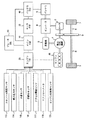
まず、本発明が適用されるハイブリッド車両の概略構成について、図1を参照して説明する。 First, a schematic configuration of a hybrid vehicle to which the present invention is applied will be described with reference to FIG.
図1に示されたハイブリッド車両は、その駆動源として、内燃機関であるエンジン100と補助動力であるモータ2とを有している。また、このハイブリッド車両は、エンジン100の出力を受けて発電を行なう発電機3も有している。これらのエンジン100、モータ2及び発電機3は、動力分割機構4を介して互いに接続されている。動力分割機構4は、例えば遊星歯車機構により構成され、エンジン100の出力を発電機3や駆動輪7に振り分ける役割や、モータ2からの出力を駆動輪7に伝達する役割を負っている。また、動力分割機構4は、ディファレンシャルギヤ5及び駆動軸6を介して駆動輪7に伝達される駆動力の変速機としての役割も負っている。
The hybrid vehicle shown in FIG. 1 has an
モータ2は、例えば交流同期モータであり、交流電力によって駆動される。インバータ9は、バッテリ8に蓄えられた電力を直流から交流に変換して、モータ2に供給すると共に、発電機3によって発電された電力を交流から直流に変換して、バッテリ8に蓄えるためのものである。発電機3も、基本的には上述したモータ2とほぼ等しい構成を有しており、交流同期モータとしての機能を有している。モータ2が主として駆動力を出力するためのものであるのに対して、発電機3は、主としてエンジン100の出力を受けて発電するためのものである。
The
なお、モータ2は、主として駆動力を発生するが、駆動輪7の回転を利用して発電(回生発電)することもできる。このとき、駆動輪7には回生ブレーキがかかるので、これをフットブレーキやエンジンブレーキと併用することにより、ハイブリッド車両を制動することができる。逆に、発電機3は、主としてエンジン100の出力を受けて発電するが、インバータ9を介してバッテリ8の電力を受けてモータとしても機能し得る。
The
ここで、本発明が適用されるデュアル噴射型内燃機関としてのエンジン100について図2を参照して説明する。エンジン100は複数の気筒を備え、各気筒はそれぞれ対応する吸気枝管102を介して共通のサージタンク103に接続されている。サージタンク103は吸気ダクト104を介してエアクリーナ105に接続されている。吸気ダクト104内にはエアフローメータ118、およびステップモータ106によって駆動されるスロットル弁107が配置されている。このスロットル弁107はアクセルペダル110の踏み込みにほぼ連動して吸気ダクト104を開閉するように制御される。一方、各気筒は共通の排気マニホルド108に連結され、この排気マニホルド108は三元触媒コンバータ109に連結されている。なお、119は燃焼室の頂部に配置された点火プラグである。
Here, an
各気筒に対しては、筒内に向けて燃料を噴射するための筒内噴射用インジェクタ111と吸気ポートまたは吸気通路内に向けて燃料を噴射するための吸気通路噴射用インジェクタ112とがそれぞれ設けられている。これらインジェクタ111、112は後述するエンジン電子制御ユニット(以下、エンジンECUと称す)20の出力信号に基づいてそれぞれ制御される。また、各筒内噴射用インジェクタ111は不図示の共通の燃料分配管に接続されており、この燃料分配管は燃料分配管に向けて流通可能な逆止弁を介して、機関駆動式の高圧燃料ポンプに接続されている。
For each cylinder, an in-
一方、各吸気通路噴射用インジェクタ112も不図示の共通の燃料分配管に接続されており、燃料分配管および高圧燃料ポンプは共通の燃料圧レギュレータを介して、電動モータ駆動式の低圧燃料ポンプに接続されている。さらに、低圧燃料ポンプは燃料フィルタを介して燃料タンクに接続されている。燃料圧レギュレータは低圧燃料ポンプから吐出された燃料の燃料圧が予め定められた設定燃料圧よりも高くなると、低圧燃料ポンプから吐出された燃料の一部を燃料タンクに戻すように構成されており、したがって吸気通路噴射用インジェクタ112に供給されている燃料圧および高圧燃料ポンプに供給されている燃料圧が上記設定燃料圧よりも高くなるのを阻止している。
On the other hand, each
上述した構成を有するハイブリッド車両では、例えば、発進時や軽負荷時には、低回転状態で高トルクを発生可能なモータ2の特性を利用して、モータ2のみをバッテリ8からの電力で駆動させてモータ2の駆動力によってハイブリッド車両を走行させる。ある程度の速度が出て、負荷も高くなってきた場合は、エンジン100を駆動させ、エンジン100の駆動力と、エンジン100の出力によって発電機3で発電した電力で駆動されるモータ2の駆動力とによってハイブリッド車両を走行させる。さらに、全開加速時等さらなる出力が必要な場合は、モータ2を発電機3からの電力とバッテリ8からの電力との双方で駆動すると共に、エンジン100の駆動力も上昇させ、エンジン100の駆動力とモータ2の駆動力とでハイブリッド車両を走行させる。また、減速時や制動時には、駆動輪7の回転力を利用してモータ2によって回生発電を行ってハイブリッド車を回生制動させる。さらに、バッテリ8の充電量が低下したような場合は、軽負荷時であってもエンジン100を駆動し、エンジン100の出力を利用して発電機3で発電を行い、インバータ9を介してバッテリ8を充電するというような使用が可能である。
In the hybrid vehicle having the above-described configuration, for example, at the time of starting or a light load, only the
ここで、上述のようにハイブリッド車両を制御する、いくつかの電子制御ユニット(ECU)について、再度、図1を参照して説明する。ハイブリッド車両として特徴的な、エンジン100による駆動とモータ2(及び発電機3)による電気的な駆動とは、メインECU10によって総合的に制御される。通常の運転状態では、メインECU10によって、エネルギー効率が最適となるように、エンジン100及びモータ2への出力配分が決定され、この要求出力配分に基づいてエンジン100、モータ2及び発電機3を制御すべく、各制御指令がエンジンECU20及びモータECU30に出力される。
Here, several electronic control units (ECUs) that control the hybrid vehicle as described above will be described again with reference to FIG. The drive by the
また、エンジンECU20及びモータECU30は、エンジン100、モータ2及び発電機3の情報をメインECU10に伝えてもいる。メインECU10には、バッテリ8を制御するバッテリECU40や、ブレーキを制御するブレーキECU50も接続されている。バッテリECU40は、バッテリ8の充電状態を監視し、充電量が不足した場合は、メインECU10に対して、充電要求指令を出力する。充電要求を受けたメインECU10は、バッテリ8に対して充電をすべく、発電機3によって発電する制御を行う。ブレーキECU50は、ハイブリッド車の制動を司っており、メインECU10と共にモータ2による回生ブレーキを制御する。
The
これらのECUはデジタルコンピュータからなり、双方向性バスを介して相互に接続されたROM(リードオンリメモリ)、RAM(ランダムアクセスメモリ)、CPU(マイクロプロセッサ)、入力ポートおよび出力ポート等を具備している。なお、エンジンECU20に対しては、以下に述べる各種センサが接続されている。すなわち、スロットルバルブ106の開度に比例した出力電圧を発生するスロットル開度センサ113、サージタンク103に取付けられ、吸入圧力に比例した出力電圧を発生する吸入圧力センサ114、エンジンブロックに取付けられ機関冷却水温に比例した出力電圧を発生する水温センサ115、触媒109上流の排気マニホルド108に取付けられた空燃比センサ116、およびアクセルペダル110に接続され、その踏込み量に比例した出力電圧を発生するアクセル開度センサ117、および吸入空気量に比例した出力電圧を発生するエアフローメータ118が、それぞれ、不図示のAD変換器を介してエンジンECU20の入力ポートに接続されている。また、入力ポートには機関回転数を表す出力パルスを発生する回転数センサ120が接続されている。
These ECUs consist of digital computers, and are equipped with ROM (Read Only Memory), RAM (Random Access Memory), CPU (Microprocessor), input port and output port, etc. which are connected to each other via a bidirectional bus. ing. Various sensors described below are connected to the
本実施形態の空燃比センサ116は、O2センサであり、排気ガス中の酸素濃度に応じてその出力が変化するという特性を有しており、空燃比センサ116の出力から、エンジン100で燃焼された混合気の空燃比が理論空燃比に対してリッチであるかリーンであるかをオン−オフ的に検出することができる。なお、空燃比センサ116としては、エンジン100で燃焼された混合気の空燃比に比例した出力電圧を発生する全域空燃比センサ(リニア空燃比センサ)を用いてもよい。エンジンECU20のROMには、上述のアクセル開度センサ117やエアフローメータ118および回転数センサ120により得られる機関負荷率および機関回転数に基づく、エンジン運転状態に対応させて設定されている燃料噴射量(燃料噴射時間)の値や分担率および機関冷却水温に基づく補正値等が予めマップ化されて記憶されている。
The air-
上述した構成を有するハイブリッド車両においては、その駆動源としてエンジン100とモータ2とを併用するので、車両としてある駆動力が必要である場合に、エンジン100の出力とモータ2の出力との配分を変更することで、車両が必要としている総出力を変更することなく、エンジン100やモータ2の出力を変更することもできる。即ち、車両としてある駆動力が必要であるとき、モータ2の出力を増やせば、その分エンジン100の出力を抑えることができ、反対にモータ2の出力を抑制すれば、その分エンジン100の出力を増やすことができる。本実施の形態の空燃比学習制御方法は、このような特性を空燃比学習制御に利用している。
In the hybrid vehicle having the above-described configuration, the
ここで、上述の構成を備えるエンジン100の空燃比学習値を学習する空燃比学習制御方法の一実施形態について、図3のフローチャートを参照して説明する。この制御は、例えば、モータ2の駆動力によってハイブリッド車両が発進開始された後の走行中の所定時期において、エンジン100が始動された直後に行われる。
Here, an embodiment of the air-fuel ratio learning control method for learning the air-fuel ratio learning value of the
まず、制御が開始されると、ステップS301で、エンジン100が定常運転可能か否かが判定される。この定常運転可能か否かの判定は、例えば、バッテリECU40からの情報によりバッテリ8に蓄えられている充電量が充分であり、モータ2による走行が可能か否かにより行うことができる。なお、アクセル開度センサ117や水温センサ115からの信号により、エンジン100に要求されている負荷が所定値を超えるときや、エンジン100の冷却水温が所定値以下のときは、定常運転不能と判定するのが好ましい。このようなときは、エンジン100の安定的な運転が保証されないからである。かくて、定常運転不能と判定されると、この制御ルーチンを一旦終了する。
First, when control is started, it is determined in step S301 whether or not the
一方、ステップS301で定常運転可能と判定されると、ステップS302に進みエンジン100が定常運転状態に設定される。この定常運転状態とは、エンジン100の例えばスロットル弁107の開度がスロットル開度センサ113による出力信号に基づき一定に制御され、且つ燃料噴射量が一定に制御されることにより、負荷率および回転数の変動を生じない状態、換言すると過渡運転でない状態をいう。なお、この定常運転状態は、運転領域を異ならせて複数個設定してもよい。その領域毎に空燃比学習制御の精度が向上するからである。
On the other hand, if it is determined in step S301 that the steady operation is possible, the process proceeds to step S302, and the
ところで、本実施の形態におけるエンジン100では、例えば、図4に示すような運転領域ないしは条件に対応して、筒内噴射用インジェクタ111と吸気通路噴射用インジェクタ112とによる噴射の分担率が定められている。図4において、「直噴100%」とは、筒内噴射用インジェクタ111からのみ噴射が行なわれる領域(X=100)であることを意味し、「直噴0〜20%」とは、筒内噴射用インジェクタ111からの噴射が0〜20%の領域(X=0〜20)であることを意味している。例えば、「直噴40%」の領域では、筒内噴射用インジェクタ111からの噴射が40%、吸気通路噴射用インジェクタ112からの噴射が60%行なわれ、両者の分担率は40:60となる。
By the way, in the
図3のフローチャートに戻り、そのステップS302において、エンジン100が定常運転状態に設定された後のステップS303において、上述の一定に制御される燃料噴射量の全量が筒内噴射用インジェクタ111からのみ噴射される、「直噴100%」での運転が実行される。そして、ステップS304において、後述する、筒内噴射用インジェクタ111に対するインジェクタ特性学習やエアフローメータ特性を含む空燃比学習制御が実行される。さらに、ステップS305に進み空燃比学習制御が完了したか否かが判定され、完了していないときはステップS304に戻り空燃比学習制御が継続される。なお、空燃比学習制御が完了したか否かの判定の手法については、後で詳述する。
Returning to the flowchart of FIG. 3, in step S <b> 303 after the
そこで、筒内噴射用インジェクタ111に対する空燃比学習制御が完了したときは、ステップS306に進み、上述の一定に制御された燃料噴射量の全量が吸気通路噴射用インジェクタ112からのみ噴射される、「直噴0%」、すなわち、「ポート噴射100%」での運転が実行される。そして、ステップS307において、吸気通路噴射用インジェクタ112に対するインジェクタ特性学習等を含む空燃比学習制御が実行される。さらに、ステップS308に進み空燃比学習制御が完了したか否かが判定され、完了していないときはステップS307に戻り空燃比学習制御が継続される。なお、上述のエンジン100の定常運転状態での空燃比学習制御中に、ハイブリッド車両からさらなる出力要求があったときには、メインECU10はエンジン100による出力は一定のまま、モータ2からの出力配分を増大するように、各制御指令がエンジンECU20及びモータECU30に出力され得ること上述の通りである。
Therefore, when the air-fuel ratio learning control for the in-
ここで、上述の筒内噴射用インジェクタ111または吸気通路噴射用インジェクタ112に対するインジェクタ特性学習を含む空燃比学習制御が完了しているか否かの判断の前提となる空燃比フィードバック及び空燃比学習制御ルーチンにつき、図5のフローチャートを参照して説明する。図5の制御ルーチンは、所定時間毎(又は所定回転毎)に実行される。まず、ステップS501では、所定の空燃比フィードバック制御領域か否かが判定される。具体的には、例えば、均質ストイキ燃焼時であり、また全開領域ではないことを条件とする。空燃比フィードバック制御領域でないときは本ルーチンを終了し(このとき空燃比フィードバック補正係数γは前回値に保持される)、成立時にのみステップS502以降へ進む。
Here, an air-fuel ratio feedback and air-fuel ratio learning control routine which is a precondition for determining whether or not the air-fuel ratio learning control including the injector characteristic learning for the in-
ここで、空燃比フィードバック補正係数γは、空燃比センサ116によって排気ガス中の酸素濃度から空燃比を検出して、この空燃比が目標空燃比になるようにフィードバック補正するためのものであり、例えば、空燃比を理論空燃比とする際には、空燃比センサ116によって検出された空燃比が理論空燃比よりもリッチである間は空燃比フィードバック補正係数γに対して燃料噴射量を徐々に減量する値が与えられ、空燃比センサ116によって検出された空燃比がリッチからリーンに変わったときには応答性向上を考慮して燃料噴射量を増量する値がスキップ的に与えられる。
Here, the air-fuel ratio feedback correction coefficient γ is for detecting the air-fuel ratio from the oxygen concentration in the exhaust gas by the air-
逆に、空燃比センサ116によって検出された空燃比が理論空燃比よりもリーンである間は空燃比フィードバック補正係数γに対して燃料噴射量を徐々に増量する値が与えられ、空燃比センサ116によって検出された空燃比がリーンからリッチに変わったときには応答性向上を考慮して燃料噴射量を減量する値がスキップ的に与えられる。このようにして、空燃比を常に理論空燃比に維持すべく、空燃比フィードバック補正係数γが生成される。
Conversely, while the air-fuel ratio detected by the air-
そこで、ステップS502では、空燃比センサ116の出力に基づき空燃比がリッチまたはリーンかが判定される。空燃比がリッチの場合は、ステップS503へ進んで空燃比フィードバック補正係数γを前回値に対し所定の積分分I減少させ、逆に、空燃比がリーンの場合は、ステップS504へ進んで空燃比フィードバック補正係数γを前回値に対し所定の積分分I増大させる。尚、リッチ・リーンの反転時には、空燃比フィードバック補正係数γを前回値に対し所定の比例分P(>>I)増減するが、説明を簡略化するために図示は省略されている。
Therefore, in step S502, it is determined whether the air-fuel ratio is rich or lean based on the output of the air-
次に、ステップS505では、空燃比フィードバック補正係数γの平均値γaveが算出される。具体的には、例えば、リッチ→リーンの反転時の空燃比フィードバック補正係数の最新の記憶値γ1と、リーン→リッチの反転時の空燃比フィードバック補正係数の最新の記憶値γ2とから、平均値γave =(γ1+γ2)/2が算出される。そして、次のステップS506では、空燃比フィードバック補正係数の平均γave の基準値「1」からの偏差Δγ=γave −1が算出される。 Next, in step S505, an average value γave of the air-fuel ratio feedback correction coefficient γ is calculated. Specifically, for example, from the latest stored value γ1 of the air-fuel ratio feedback correction coefficient at the time of inversion of rich → lean and the latest stored value γ2 of the air-fuel ratio feedback correction coefficient at the time of inversion of lean → rich, an average value is obtained. γave = (γ1 + γ2) / 2 is calculated. In the next step S506, a deviation Δγ = γave −1 from the reference value “1” of the average γave of the air-fuel ratio feedback correction coefficient is calculated.
そして、ステップS507では、次式のごとく、現在の空燃比学習値Lγに上記偏差Δγの所定割合G(Gは学習ゲインで、0<G<1)が加算されて、新たな空燃比学習値Lγが算出される。 In step S507, a predetermined ratio G of the deviation Δγ (G is a learning gain, 0 <G <1) is added to the current air-fuel ratio learned value Lγ, as shown in the following equation, and a new air-fuel ratio learned value is obtained. Lγ is calculated.
Lγ=Lγ+Δγ×G
そして、ステップS508に進み、学習回数のカウンタを1だけカウントアップし、学習回数カウント値「n」を算出する。さらに、ステップS509に進み、この学習回数カウント値「n」が所定回数(例えば、30回)以上であるか否かが判断される。学習回数カウント値「n」が所定回数を超えたとき、すなわち「Yes」のときはステップS510に進み、空燃比学習値が更新される。詳しくは、上述のステップS507で算出された空燃比学習値「Lγ」が、学習成果が反映された空燃比学習反映値とされるのである。そして、ステップS511において、空燃比学習完了フラグFがオン(=1)にセットされる。一方、所定回数を超えないとき、すなわち「No」のときは、学習精度が充分でないとしてステップS512に進み、空燃比学習値の更新が禁止される。そして、ステップS513において、空燃比学習完了フラグFがオフ(=0)にセットされる。
Lγ = Lγ + Δγ × G
In step S508, the learning count counter is incremented by 1, and the learning count value “n” is calculated. In step S509, it is determined whether the learning number count value “n” is equal to or greater than a predetermined number (for example, 30 times). When the learning number count value “n” exceeds the predetermined number, that is, “Yes”, the process proceeds to step S510, and the air-fuel ratio learning value is updated. Specifically, the air-fuel ratio learning value “Lγ” calculated in step S507 described above is used as the air-fuel ratio learning reflecting value reflecting the learning result. In step S511, the air-fuel ratio learning completion flag F is set to on (= 1). On the other hand, when the predetermined number of times is not exceeded, that is, when “No”, the learning accuracy is not sufficient and the process proceeds to step S512, and the update of the air-fuel ratio learning value is prohibited. In step S513, the air-fuel ratio learning completion flag F is set to off (= 0).
従って、前述した図3のフローチャートのステップS305またはステップS308における、筒内噴射用インジェクタ111または吸気通路噴射用インジェクタ112に対するインジェクタ特性学習を含む空燃比学習制御が完了しているか否かの判断は、上記空燃比学習完了フラグFがオンまたはオフであるかにより行うことができる。
Therefore, in step S305 or step S308 of the flowchart of FIG. 3 described above, the determination as to whether the air-fuel ratio learning control including the injector characteristic learning for the in-
なお、筒内噴射用インジェクタ111および吸気通路噴射用インジェクタ112のいずれについても空燃比学習制御が完了した後は、図3のフローチャートのステップS309に進み、通常の分担率による噴き分け許可フラグをオンとしてルーチンを終了する。この噴き分け許可フラグがオンとされた後は、筒内噴射用インジェクタ111および吸気通路噴射用インジェクタ112の両者から運転条件等に応じて所定の分担率で燃料が噴射されて運転され得るのである。
After the air-fuel ratio learning control is completed for both the in-
以上述べたように、本実施の形態では、エンジン100の燃料噴射量に変動がない定常運転状態で空燃比学習制御が実行されるので、正確且つ速やかに空燃比学習制御を行なうことができる。また、筒内噴射用インジェクタおよび吸気通路噴射用インジェクタのいずれか一方ずつに対して空燃比学習制御が実行されるので、両インジェクタの各々についての空燃比学習制御を早期に、しかも正確に行なうことができる。
As described above, in the present embodiment, since the air-fuel ratio learning control is executed in a steady operation state in which the fuel injection amount of the
今回開示された実施の形態は、すべての点で例示であって制限的なものではないと考えられるべきである。本発明の範囲は、上記した実施の形態の説明ではなくて特許請求の範囲によって示され、特許請求の範囲と均等の意味および範囲内でのすべての変更が含まれることが意図される。 The embodiment disclosed this time should be considered as illustrative in all points and not restrictive. The scope of the present invention is shown not by the above description of the embodiments but by the scope of claims for patent, and is intended to include meanings equivalent to the scope of claims for patent and all modifications within the scope.
10 メインECU
20 エンジンECU
100 エンジン(デュアル噴射型内燃機関)
111 筒内噴射用インジェクタ
112 吸気通路噴射用インジェクタ
116 空燃比センサ
10 Main ECU
20 Engine ECU
100 engine (dual injection internal combustion engine)
111 In-
Claims (2)
前記内燃機関の空燃比学習値を学習する空燃比学習制御実行の際には、前記内燃機関を定常運転させ、前記筒内噴射用インジェクタおよび前記吸気通路噴射用インジェクタのいずれか一方からのみ燃料を噴射させて空燃比学習制御を実行するステップと、
その学習制御が完了した後、前記筒内噴射用インジェクタおよび前記吸気通路噴射用インジェクタのいずれか他方からのみ燃料を噴射させて空燃比学習制御を実行するステップとを備える、車両におけるデュアル噴射型内燃機関の空燃比学習制御方法。 In a vehicle driven by a dual injection type internal combustion engine including an in-cylinder injector and an intake manifold injector,
When the air-fuel ratio learning control for learning the air-fuel ratio learning value of the internal combustion engine is executed, the internal combustion engine is steadily operated, and fuel is supplied from only one of the in-cylinder injector and the intake manifold injector. Injecting and executing air-fuel ratio learning control;
A dual-injection internal combustion engine for a vehicle, comprising: a step of performing air-fuel ratio learning control by injecting fuel only from one of the in-cylinder injector and the intake manifold injector after the learning control is completed Engine air-fuel ratio learning control method.
Priority Applications (1)
| Application Number | Priority Date | Filing Date | Title |
|---|---|---|---|
| JP2008287545A JP2009030615A (en) | 2008-11-10 | 2008-11-10 | Method of controlling learning of air-fuel ratio of dual-injection internal combustion engine on vehicle |
Applications Claiming Priority (1)
| Application Number | Priority Date | Filing Date | Title |
|---|---|---|---|
| JP2008287545A JP2009030615A (en) | 2008-11-10 | 2008-11-10 | Method of controlling learning of air-fuel ratio of dual-injection internal combustion engine on vehicle |
Related Parent Applications (1)
| Application Number | Title | Priority Date | Filing Date |
|---|---|---|---|
| JP2004152188A Division JP4442318B2 (en) | 2004-05-21 | 2004-05-21 | Air-fuel ratio learning control method and air-fuel ratio learning control device for dual injection internal combustion engine in hybrid vehicle |
Publications (2)
| Publication Number | Publication Date |
|---|---|
| JP2009030615A true JP2009030615A (en) | 2009-02-12 |
| JP2009030615A5 JP2009030615A5 (en) | 2009-04-02 |
Family
ID=40401357
Family Applications (1)
| Application Number | Title | Priority Date | Filing Date |
|---|---|---|---|
| JP2008287545A Pending JP2009030615A (en) | 2008-11-10 | 2008-11-10 | Method of controlling learning of air-fuel ratio of dual-injection internal combustion engine on vehicle |
Country Status (1)
| Country | Link |
|---|---|
| JP (1) | JP2009030615A (en) |
Cited By (6)
| Publication number | Priority date | Publication date | Assignee | Title |
|---|---|---|---|---|
| JP2011169273A (en) * | 2010-02-19 | 2011-09-01 | Mitsubishi Motors Corp | Internal combustion engine |
| JP2012031859A (en) * | 2010-07-29 | 2012-02-16 | Robert Bosch Gmbh | Method and device for control of internal combustion engine |
| JP2014092062A (en) * | 2012-11-02 | 2014-05-19 | Toyota Motor Corp | Control device for internal combustion engine and hybrid vehicle |
| US9366198B2 (en) | 2014-01-16 | 2016-06-14 | Honda Motor Co., Ltd. | Malfunction judging apparatus for fuel feeding apparatus and malfunction judging method for fuel feeding apparatus |
| JP2017194019A (en) * | 2016-04-21 | 2017-10-26 | トヨタ自動車株式会社 | Internal combustion device |
| JP2018009478A (en) * | 2016-07-12 | 2018-01-18 | トヨタ自動車株式会社 | Fuel injection control device of engine |
Citations (4)
| Publication number | Priority date | Publication date | Assignee | Title |
|---|---|---|---|---|
| JPS61200436U (en) * | 1985-06-04 | 1986-12-15 | ||
| JPH0436036A (en) * | 1990-05-11 | 1992-02-06 | Mazda Motor Corp | Air-fuel ratio controller of engine |
| JP2003129887A (en) * | 2001-10-19 | 2003-05-08 | Nissan Motor Co Ltd | Device for controlling fuel injection in internal combustion engine |
| JP2005330939A (en) * | 2004-05-21 | 2005-12-02 | Toyota Motor Corp | Air-fuel ratio learning control method for dual jet type internal combustion engine in hybrid vehicle |
-
2008
- 2008-11-10 JP JP2008287545A patent/JP2009030615A/en active Pending
Patent Citations (4)
| Publication number | Priority date | Publication date | Assignee | Title |
|---|---|---|---|---|
| JPS61200436U (en) * | 1985-06-04 | 1986-12-15 | ||
| JPH0436036A (en) * | 1990-05-11 | 1992-02-06 | Mazda Motor Corp | Air-fuel ratio controller of engine |
| JP2003129887A (en) * | 2001-10-19 | 2003-05-08 | Nissan Motor Co Ltd | Device for controlling fuel injection in internal combustion engine |
| JP2005330939A (en) * | 2004-05-21 | 2005-12-02 | Toyota Motor Corp | Air-fuel ratio learning control method for dual jet type internal combustion engine in hybrid vehicle |
Cited By (10)
| Publication number | Priority date | Publication date | Assignee | Title |
|---|---|---|---|---|
| JP2011169273A (en) * | 2010-02-19 | 2011-09-01 | Mitsubishi Motors Corp | Internal combustion engine |
| JP2012031859A (en) * | 2010-07-29 | 2012-02-16 | Robert Bosch Gmbh | Method and device for control of internal combustion engine |
| JP2014092062A (en) * | 2012-11-02 | 2014-05-19 | Toyota Motor Corp | Control device for internal combustion engine and hybrid vehicle |
| KR20150036645A (en) * | 2012-11-02 | 2015-04-07 | 도요타 지도샤(주) | Apparatus for controlling the learning of the air fuel ratio of an internal combustion engine |
| US9243575B2 (en) | 2012-11-02 | 2016-01-26 | Toyoda Jidosha Kabushiki Kaisha | Apparatus for controlling the learning of the air fuel ratio of an internal combustion engine |
| KR101695112B1 (en) | 2012-11-02 | 2017-01-10 | 도요타 지도샤(주) | Apparatus for controlling the learning of the air fuel ratio of an internal combustion engine |
| DE112013003528B4 (en) * | 2012-11-02 | 2021-01-14 | Toyota Jidosha Kabushiki Kaisha | Apparatus for controlling the learning of the air-fuel ratio of an internal combustion engine |
| US9366198B2 (en) | 2014-01-16 | 2016-06-14 | Honda Motor Co., Ltd. | Malfunction judging apparatus for fuel feeding apparatus and malfunction judging method for fuel feeding apparatus |
| JP2017194019A (en) * | 2016-04-21 | 2017-10-26 | トヨタ自動車株式会社 | Internal combustion device |
| JP2018009478A (en) * | 2016-07-12 | 2018-01-18 | トヨタ自動車株式会社 | Fuel injection control device of engine |
Similar Documents
| Publication | Publication Date | Title |
|---|---|---|
| JP4442318B2 (en) | Air-fuel ratio learning control method and air-fuel ratio learning control device for dual injection internal combustion engine in hybrid vehicle | |
| US8972089B2 (en) | Hybrid vehicle | |
| US9008877B2 (en) | Hybrid vehicle and method of controlling the same | |
| JP4615037B2 (en) | Hybrid vehicle and control method thereof | |
| JP2009083847A (en) | Method for operating electric machine in hybrid electric vehicle | |
| JP2008284909A (en) | Vehicle and its control method | |
| WO2010079609A1 (en) | Control device for vehicle | |
| JP2008120266A (en) | Fuel property estimating apparatus of hybrid vehicle | |
| JP2007224848A (en) | Internal combustion engine controller | |
| US20140309832A1 (en) | Hybrid vehicle | |
| JP2009030615A (en) | Method of controlling learning of air-fuel ratio of dual-injection internal combustion engine on vehicle | |
| JP2008105632A (en) | Power output device, internal combustion engine, control method therefor, and vehicle | |
| US20190291715A1 (en) | Control device of hybrid vehicle | |
| JP4281784B2 (en) | INTERNAL COMBUSTION ENGINE DEVICE, POWER OUTPUT DEVICE EQUIPPED WITH THE SAME, VEHICLE MOUNTING THE SAME, METHOD FOR CONTROLLING INTERNAL COMBUSTION ENGINE DEVICE | |
| JP2009262753A (en) | Hybrid car and its control method | |
| JPWO2012081111A1 (en) | Control device for internal combustion engine | |
| JP2009279987A (en) | Fuel injection control device for internal combustion engine | |
| JP2000291471A (en) | Air-fuel ratio learning controller | |
| JP2007120382A (en) | Power output device, method for controlling the same and vehicle | |
| US11149671B2 (en) | Vehicle system | |
| JP2010221744A (en) | Vehicle control device | |
| US10710573B2 (en) | Vehicle and control method of vehicle | |
| JP5077045B2 (en) | Control device for internal combustion engine | |
| JP7444081B2 (en) | Internal combustion engine control device | |
| WO2022163410A1 (en) | Drive control device and drive control method |
Legal Events
| Date | Code | Title | Description |
|---|---|---|---|
| A621 | Written request for application examination |
Free format text: JAPANESE INTERMEDIATE CODE: A621 Effective date: 20081110 |
|
| A521 | Written amendment |
Free format text: JAPANESE INTERMEDIATE CODE: A523 Effective date: 20090217 |
|
| A131 | Notification of reasons for refusal |
Free format text: JAPANESE INTERMEDIATE CODE: A131 Effective date: 20110405 |
|
| A02 | Decision of refusal |
Free format text: JAPANESE INTERMEDIATE CODE: A02 Effective date: 20110802 |