JP2009022096A - Rotor for motor and brushless motor - Google Patents
Rotor for motor and brushless motor Download PDFInfo
- Publication number
- JP2009022096A JP2009022096A JP2007182310A JP2007182310A JP2009022096A JP 2009022096 A JP2009022096 A JP 2009022096A JP 2007182310 A JP2007182310 A JP 2007182310A JP 2007182310 A JP2007182310 A JP 2007182310A JP 2009022096 A JP2009022096 A JP 2009022096A
- Authority
- JP
- Japan
- Prior art keywords
- shaft
- rotor
- back yoke
- motor
- rotating shaft
- Prior art date
- Legal status (The legal status is an assumption and is not a legal conclusion. Google has not performed a legal analysis and makes no representation as to the accuracy of the status listed.)
- Withdrawn
Links
Images


Abstract
Description
本発明はロータ及びブラシレスモータに係り、特に、回転時に発生する振動を抑え、且つ、イナーシャを低減する構造を有するモータのロータ及びこのロータを用いたブラシレスモータに関する。 The present invention relates to a rotor and a brushless motor, and more particularly to a rotor of a motor having a structure that suppresses vibrations generated during rotation and reduces inertia, and a brushless motor using the rotor.
インナロータ型のブラシレスモータでは、ステータ(固定子)側に巻き線を備え、ロータ(回転子)側に永久磁石を備えている。ロータとしては、回転軸の周りに永久磁石を配設した構成を有しており、バックヨークを介して回転軸と永久磁石が固定されたものが知られている。このバックヨークは、回転軸と永久磁石を一緒に回転するように固定するための機能と共に、永久磁石の磁束を効率よく通す磁路としての機能を併せ有している。 In an inner rotor type brushless motor, a winding is provided on the stator (stator) side, and a permanent magnet is provided on the rotor (rotor) side. As a rotor, there is known a configuration in which a permanent magnet is disposed around a rotating shaft, and the rotating shaft and the permanent magnet are fixed via a back yoke. This back yoke has the function of fixing the rotating shaft and the permanent magnet so as to rotate together, and also the function of a magnetic path for efficiently passing the magnetic flux of the permanent magnet.
一般的なインナモータ型ブラシレスモータの場合、モータの出力を外部に取り出す回転軸は、ロータの外径に比して小さな外径を有している。高出力のブラシレスモータを得るには、ロータに取付けられる永久磁石の磁束量を多くすることが必要になるが、そのためには着磁面の面積を多くする必要があり、永久磁石の外形寸法を大きくすることになる。また、永久磁石は比較的高価な部品であるため、永久磁石の肉厚は極力薄くした方がコスト的に有利である。 In the case of a general inner motor type brushless motor, the rotating shaft for taking out the output of the motor has an outer diameter smaller than the outer diameter of the rotor. In order to obtain a high-output brushless motor, it is necessary to increase the amount of magnetic flux of the permanent magnet attached to the rotor. To this end, it is necessary to increase the area of the magnetized surface, and the outer dimensions of the permanent magnet are reduced. Will be bigger. Further, since the permanent magnet is a relatively expensive part, it is advantageous in terms of cost to make the thickness of the permanent magnet as thin as possible.
すなわち、バックヨークの外周面に固着される永久磁石は、回転軸の外径よりも大きな内径を有する環状の形状を有することとなり、結果として回転軸の外周面から離れた位置に配設される。
そのため、回転軸と永久磁石の間に生じた空間を中実のバックヨークで構成すると、バックヨークは大きな容積を占めることになる。
That is, the permanent magnet fixed to the outer peripheral surface of the back yoke has an annular shape having an inner diameter larger than the outer diameter of the rotating shaft, and as a result, is disposed at a position away from the outer peripheral surface of the rotating shaft. .
Therefore, if the space formed between the rotating shaft and the permanent magnet is configured by a solid back yoke, the back yoke occupies a large volume.
バックヨークは、磁路を確保するための部材であるためケイ素鋼板などの鉄損の少ない材質で構成される。前記構造のように永久磁石と回転軸の間の空間を中実のバックヨークで満たすと、比重の重い鉄製であるバックヨークは、ロータの構成要素の中でもかなり大きな重量比を占めることになる。 Since the back yoke is a member for securing a magnetic path, the back yoke is made of a material having a small iron loss such as a silicon steel plate. When the space between the permanent magnet and the rotating shaft is filled with a solid back yoke as in the above-described structure, the back yoke made of iron having a high specific gravity occupies a considerably large weight ratio among the components of the rotor.
しかし、モータの駆動時にバックヨークを通過する磁力線は、バックヨークの内部全体に渡って均一に通過しているわけではなく、磁路として使われない部分が存在するとともに、磁束密度が小さく回転特性に影響の少ない部分もある。 However, the lines of magnetic force that pass through the back yoke when the motor is driven do not pass uniformly over the entire interior of the back yoke, and there are portions that are not used as magnetic paths, and the magnetic flux density is small and the rotational characteristics. There is also a part that has little influence on.
すなわち、ロータとして無駄な質量を有していることになり、その分、ロータの質量が重くなっている。ロータ質量の増加はイナーシャの増大に結びつき、モータの応答性や、操作フィーリングが低下する原因となっていた。 That is, the rotor has a useless mass, and the mass of the rotor is increased accordingly. An increase in rotor mass has led to an increase in inertia, which has caused a decrease in motor responsiveness and operational feeling.
ロータのイナーシャを低減させる方法の一つとして、ロータの軽量化、特にバックヨークの中空化による軽量化が提案されている(例えば、特開平9−275652号公報、特開2006−320050号公報)。 As one method for reducing the inertia of the rotor, weight reduction of the rotor, in particular, weight reduction by hollowing the back yoke has been proposed (for example, Japanese Patent Laid-Open Nos. 9-275552 and 2006-320050). .
特開平9−275652号公報で提案された技術では、ロータの軽量化手段としてバックヨークを構成する積層コアの内径を、磁路に影響を与えない範囲内で肉抜きを行うことでバックヨーク内に空間部を設けている。 In the technique proposed in Japanese Patent Laid-Open No. 9-275552, the inner diameter of the laminated core constituting the back yoke is reduced within the range not affecting the magnetic path as a means for reducing the weight of the rotor. Is provided with a space.
しかし、前記提案構造では、積層コアの打ち抜きや積層のための工数が必要となりコスト上不利である。また、回転軸を挿着するためのコアの強度を確保しなければならず、バックヨークの中心部では肉厚となっていた。さらに、ロータヨークの空間部は個々に離れて設置されるため、コアの空間部分を大きくするには限界があり、十分な質量低減ができなかった。 However, the proposed structure is disadvantageous in cost because it requires man-hours for punching and stacking the laminated core. Further, the strength of the core for inserting the rotating shaft has to be ensured, and the center portion of the back yoke is thick. Further, since the space portions of the rotor yoke are installed separately from each other, there is a limit to increasing the space portion of the core, and sufficient mass reduction cannot be performed.
また、特開2006−320050号公報で提案された技術では、バックヨークを環状の中空形状として軸方向両端に複数の回転軸が形成される構造としている。この提案構造では、ロータの質量は低減できるが、分離された複数の回転軸が存在するために、回転軸の同軸度が低下し、回転振れが大きくなるという問題があった。 In the technique proposed in Japanese Patent Application Laid-Open No. 2006-320050, the back yoke has an annular hollow shape and a plurality of rotation shafts are formed at both axial ends. In this proposed structure, the mass of the rotor can be reduced. However, since there are a plurality of separated rotating shafts, there is a problem that the degree of coaxiality of the rotating shafts is reduced and rotational runout is increased.
本発明の目的は、ロータ重量を軽減してイナーシャの低減を図り、モータの応答性を向上することが可能なモータのロータおよびブラシレスモータを提供することである。
本発明の他の目的は、低コスト、及び安定した品質で製造でき、且つ、ロータの同軸精度を向上して回転時に発生する振動を低減することが可能なモータのロータおよびブラシレスモータを提供することである。
An object of the present invention is to provide a motor rotor and a brushless motor capable of reducing inertia and reducing inertia and improving motor responsiveness.
Another object of the present invention is to provide a motor rotor and a brushless motor that can be manufactured with low cost and stable quality, and that can improve the coaxial accuracy of the rotor and reduce vibrations generated during rotation. That is.
前記課題は、請求項1に係るモータのロータによれば、軸部および該軸部から径方向に延出する円板状のフランジ部を備えた回転軸と、該回転軸の軸部に平行且つ径方向に離間すると共に、前記フランジ部外周と当接して配置された円筒状の磁性体からなるバックヨークと、該バックヨークの外周に固着される円筒状の永久磁石と、前記バックヨークの軸端部側に当接すると共に前記回転軸の軸部が貫通した保持体と、を有してなるモータのロータであって、前記バックヨークの軸端部側と前記フランジ部の外周との当接面は、互いに軸方向に対し傾斜して当接する傾斜面として形成されてなること、により解決される。
According to the rotor of the motor according to
このように、バックヨークの軸端部側とフランジ部の外周との当接面は、互いに軸方向に対し傾斜して当接する傾斜面として形成されているので、フランジ部の傾斜面は、バックヨークの傾斜部分で当接し、傾斜面に沿って、バックヨークの保持体側の端部を回転軸の軸線上に誘導する、所謂調芯機能をもたせることができ、部品間の寸法誤差や組み立て誤差を吸収でき、同軸精度を向上させ周方向の振れを規制し、回転振れの少ないモータのロータが得られる。 As described above, the contact surface between the shaft end portion side of the back yoke and the outer periphery of the flange portion is formed as an inclined surface that contacts with each other while being inclined with respect to the axial direction. It is possible to provide a so-called alignment function that abuts at the inclined portion of the yoke and guides the end of the back yoke on the holding body side along the inclined surface onto the axis of the rotation axis. Can be absorbed, the coaxial accuracy is improved, the circumferential deflection is restricted, and a motor rotor with little rotational deflection is obtained.
前記課題は、請求項2に係るモータのロータによれば、軸部および該軸部から径方向に延出する円板状のフランジ部を備えた回転軸と、該回転軸の軸部に平行且つ径方向に離間すると共に、前記フランジ部外周と当接して配置された円筒状の磁性体からなるバックヨークと、該バックヨークの外周に固着される円筒状の永久磁石と、前記バックヨークの軸端部側に当接すると共に前記回転軸の軸部が貫通した保持体と、を有してなるモータのロータであって、前記バックヨークの軸端部側と前記保持体の外周との当接面は、互いに軸方向に対し傾斜して当接する傾斜面として形成されてなること、により解決される。
According to the rotor of the motor according to
このように、バックヨークの軸端部側と保持体の外周との当接面は、互いに軸方向に対し傾斜して当接する傾斜面として形成されているので、保持体の傾斜面は、バックヨークの傾斜部分で当接し、傾斜面に沿って、バックヨークの保持体側の端部を回転軸の軸線上に誘導する、所謂調芯機能をもたせることができ、部品間の寸法誤差や組み立て誤差を吸収でき、同軸精度を向上させ周方向の振れを規制し、回転振れの少ないモータのロータが得られる。 As described above, the contact surface between the shaft end side of the back yoke and the outer periphery of the holding body is formed as an inclined surface that is inclined with respect to the axial direction, so that the inclined surface of the holding body is the back surface. It is possible to provide a so-called alignment function that abuts at the inclined portion of the yoke and guides the end of the back yoke on the holding body side along the inclined surface onto the axis of the rotation axis. Can be absorbed, the coaxial accuracy is improved, the circumferential runout is restricted, and a motor rotor with less rotational runout can be obtained.
より具体的には、請求項3のように、前記バックヨークの両軸端部側には、傾斜面を有する傾斜凹部又は傾斜凸部が所定間隔で形成されていると、好適である。
さらに具体的には、請求項4のように、前記保持体は、前記バックヨークの傾斜凹部又は傾斜凸部との当接部分に、傾斜凸部又は傾斜凹部が所定間隔で形成されていると、好適である。
More specifically, as in
More specifically, as in
このように、バックヨークの軸端部側と、保持体との当接部分に、一方に傾斜凹部又は傾斜凸部、他方に傾斜凸部又は傾斜凹部を形成することにより、バックヨークと保持体との間で、特別な部材を必要としないで、回転方向の相対移動を防止し、周方向の規制を行い、より強固に固着することが可能となる。 Thus, the back yoke and the holding body are formed by forming the inclined concave portion or the inclined convex portion on one side and the inclined convex portion or the inclined concave portion on the other side at the contact portion between the shaft end portion side of the back yoke and the holding body. Therefore, it is possible to prevent relative movement in the rotational direction, regulate in the circumferential direction, and more firmly fix without requiring a special member.
前記課題は、請求項5に係るモータのロータによれば、軸部および該軸部から径方向に延出する円板状のフランジ部を備えた回転軸と、該回転軸の軸部に平行且つ径方向に離間すると共に、前記フランジ部外周と当接して配置された円筒状の磁性体からなるバックヨークと、該バックヨークの外周に固着される円筒状の永久磁石と、前記バックヨークの軸端部側に当接すると共に前記回転軸の軸部が貫通した保持体と、を有してなるモータのロータであって、前記保持体は、前記バックヨークの傾斜凹部又は傾斜凸部との当接部分に、傾斜凸部又は傾斜凹部が所定間隔で形成される底部と、該底部と連続した開口部を備えた中空円筒体と、該中空円筒体の開口部の自由端に所定間隔で形成された爪部と、を有し、前記回転軸から延出されたフランジ部と、前記爪部とをかしめ固定したこと、により解決される。
According to the rotor of the motor according to
このように、保持体は、バックヨークの傾斜凹部又は傾斜凸部との当接部分に、傾斜凸部又は傾斜凹部が所定間隔で形成される底部を有しているので、保持体の底部の傾斜面は、バックヨークの傾斜部分で当接し、傾斜面に沿って、バックヨークの保持体側の端部を回転軸の軸線上に誘導することができ、周方向の振れを規制し、同軸度の高いモータのロータが得られる。
また、保持体は、底部と連続した開口部を備えた中空円筒体と、この中空円筒体の開口部の自由端に所定間隔で形成された爪部と、を有し、回転軸から延出されたフランジ部と、爪部とをかしめ固定しているので、保持体それ自体で磁石の飛散防止用のカバーとすることが可能となる。そして、中空円筒体からなる保持体は、プレス加工が可能であり、開口部の自由端に所定間隔で形成された爪部によって回転軸のフランジ部とかしめ固着でき、部品点数を削減すると共に、組み立てが容易で、且つイナーシャの低減を図ることができる。
As described above, the holding body has a bottom portion in which the inclined convex portions or the inclined concave portions are formed at predetermined intervals in the contact portion with the inclined concave portion or the inclined convex portion of the back yoke. The inclined surface comes into contact with the inclined portion of the back yoke, and the end portion of the back yoke on the holding body side can be guided along the inclined surface on the axis of the rotating shaft, thereby regulating the circumferential deflection and the coaxiality A high motor rotor can be obtained.
The holding body includes a hollow cylindrical body having an opening continuous with the bottom, and a claw formed at a predetermined interval at a free end of the opening of the hollow cylindrical body, and extends from the rotation shaft. Since the flange portion and the claw portion are caulked and fixed, the holder itself can be used as a cover for preventing the scattering of the magnet. And the holding body made of a hollow cylindrical body can be pressed, and can be caulked and fixed to the flange portion of the rotating shaft by a claw portion formed at a predetermined interval at the free end of the opening, reducing the number of parts, Assembling is easy, and inertia can be reduced.
前記課題は請求項6乃至10のように、永久磁石でバックヨークと同様な形状として、バックヨークを省略するように構成しても、前記各請求項と同様な作用を奏することが可能となる。 Even if the subject has a shape similar to that of the back yoke with a permanent magnet as in claims 6 to 10 and the back yoke is omitted, the same effect as in the above claims can be obtained. .
前記課題は、請求項11に係るブラシレスモータによれば、請求項1乃至10のいずれか1項に記載のモータのロータを有すること、により解決される。
このように、本発明のブラシレスモータは、請求項1乃至10の特徴を備えたものを得ることが可能となる。
According to a brushless motor according to an eleventh aspect, the problem is solved by including the rotor of the motor according to any one of the first to tenth aspects.
Thus, the brushless motor of the present invention can be obtained with the features of
本発明に係るモータのロータによれば、フランジ部の傾斜面は、当接する傾斜部分で当接し傾斜面に沿って、保持体側の端部を回転軸の軸線上に誘導することができるため、トルク伝達の機能を損なうことなくロータ重量を軽減してイナーシャの低減を図り、モータの応答性を向上すると共に、各部品の寸法誤差・組み立て誤差を吸収して同軸精度を向上して回転時に発生する振動を低減することが可能なモータのロータを提供することができる。 According to the rotor of the motor according to the present invention, the inclined surface of the flange portion abuts at the abutting inclined portion, and the end on the holding body side can be guided along the inclined surface on the axis of the rotating shaft. Reduces the rotor weight without impairing the torque transmission function, reduces inertia, improves motor responsiveness, absorbs dimensional and assembly errors of each component, improves coaxial accuracy, and occurs during rotation It is possible to provide a motor rotor capable of reducing vibrations that occur.
また、本発明に係るブラシレスモータによれば、トルク伝達の機能を損なうことなくロータ重量を軽減してイナーシャの低減を図り、モータの応答性を向上すると共に、各部品の寸法誤差・組み立て誤差を吸収して同軸精度を向上して回転時に発生する振動を低減することが可能なブラシレスモータを提供することができる。 Further, according to the brushless motor of the present invention, the rotor weight is reduced without impairing the torque transmission function to reduce the inertia, the motor response is improved, and the dimensional error and assembly error of each component are reduced. It is possible to provide a brushless motor that can absorb and improve the coaxial accuracy to reduce vibration generated during rotation.
以下、本発明の実施の形態について、ブラシレスモータ1を例にとって図面を参照して説明する。なお、以下に説明する部材,配置等は本発明を限定するものでなく、本発明の趣旨の範囲内で種々改変することができることは勿論である。
Embodiments of the present invention will be described below with reference to the drawings, taking the
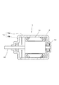
図1乃至図3は本発明に係る第1の実施形態を示し、図1はブラシレスモータの断面説明図、図2は図1に示したロータの断面説明図、図3はロータの分解斜視図である。 1 to 3 show a first embodiment of the present invention, FIG. 1 is a cross-sectional explanatory view of a brushless motor, FIG. 2 is a cross-sectional explanatory view of the rotor shown in FIG. 1, and FIG. 3 is an exploded perspective view of the rotor It is.
先ず、図1に基づき、本発明の実施形態に係るインナロータ型のブラシレスモータ1の構成を説明する。
本例のブラシレスモータ1は、回転軸20と一体となったロータ2と、このロータ2を回転可能に支承する軸受13と、巻線を有するステータ14と、これらを収納するヨークハウジング15とを備えている。
First, based on FIG. 1, the structure of the inner rotor
The
本例のヨークハウジング15は、中空円筒状のセンタハウジング15aと、このセンタハウジング15aの一方の開口端部を閉塞する略円板上のフロントハウジング15bとから構成されている。そして、センタハウジング15aの内側には、ステータ14が設けられ、このステータ14は、図示しない鉄芯部にそれぞれ各相の巻線が巻回されて構成されており、ヨークハウジング15の内側面に当接するように配設されている。またセンタハウジング15a及びフロントハウジング15bの底部には、それぞれ軸受13が配設されている。
The
また、図示しないが、ブラシレスモータ1には、ホール素子、位置検出用磁石などから構成される周知の位置検出器や制御回路が備えられており、これらによってロータ2の回転中の位置検出が行われる。この位置検出によって得られる信号と速度設定値を基に、制御回路から巻線に電流が与えられることにより、ステータ14に回転磁界が発生しロータ2は安定して回転するように構成されている。
Although not shown, the
本例のロータ2は、回転軸20と、フランジ部21と、保持体25と、バックヨーク30と、永久磁石35とから構成されている。
The
本例の回転軸20は、ロータ2の出力軸となっており、回転軸20はヨークハウジング15内に設けられた軸受13により回転自在に軸支されている。回転軸20の外径は、バックヨーク30の内径より小さく形成され、回転軸20には、フランジ部21が一体に形成されている。回転軸20はアルミニウム合金やステンレスによっても形成することができ、また、金属の代わりに樹脂などのより軽量な材質で形成することもできる。
The rotating
回転軸20は、モータで発生したトルクの伝達を担う部材であるとともに、回転振れを防止する観点から高い寸法精度が要求される部材である。低炭素鋼のように好適な加工性と、ある程度の機械的強度を有する材料から形成されており、冷間鍛造後に切削加工が施されている。
The rotating
本例のバックヨーク30は、パイプ材を用いて中空円筒状に形成されており、バックヨーク30の内径を回転軸20の外径よりも大きくし、バックヨーク30の一方の軸端部に、前記した回転軸20と一体に形成されたフランジ部21を配設し、もう一方の軸端部に後述する保持体25を配設して、フランジ部21と保持体25でバックヨーク30の両端側を挟持することでバックヨーク30と回転軸20の間に空間部34を形成している。
The
そして、本例のバックヨーク30の両軸端部側には、図3で示すように、それぞれ内側面に傾斜面を有する凹部(傾斜凹部31a,31b)が90度間隔で、回転軸20の中心を対称として4箇所に形成されている。
傾斜凹部31a,31bの傾斜面は、バックヨーク30の端部側の内面側を、軸方向に対し傾斜角度を付けて研削することで形成されている。また、円周方向には、バックヨーク30内側の曲率に沿って湾曲した形状を有している。
Further, as shown in FIG. 3, concave portions (inclined
The inclined surfaces of the inclined
バックヨーク30は磁路を形成する部材であり、磁性材料であるケイ素鋼板や低炭素鋼に相当する材質で形成されている。このバックヨーク30の形状は、磁路を形成できる形状であればよく、例えば、内側面や外側面に凹凸を有する形状や、磁路に影響を与えない範囲内に複数の貫通した孔部が形成された形状でも適用可能である。
The
本例のフランジ部21は、回転軸20の軸部から径方向に延出された円板状の部材であり、フランジ部21の外縁部には、傾斜突起部22が軸方向に形成されている。
フランジ部21の外縁部に形成された傾斜突起部22の外周面には、傾斜面22aが形成されており、この傾斜突起部22aがバックヨーク30に形成された傾斜凹部31aに沿って嵌合される。
The
An
このとき、フランジ部21の傾斜面22aは、バックヨーク30の傾斜凹部31aで当接し傾斜面に沿って、バックヨーク30のフランジ部21側の端部を回転軸20の軸線上に誘導する。
At this time, the
本例の保持体25は略円板状の部材であり、中央部の片面側に略円形の凸形段差26が形成されている。凸形段差26の外周面には嵌合部としての突起27が径方向に90度間隔で、軸中心を対称として4箇所に形成されており、突起27の外周面には傾斜面27aが形成されている。本例の保持体25の材質は低炭素鋼で形成されているが、樹脂材料、アルミニウム合金、ステンレス合金などの材質で形成することもできる。
The holding
保持体25をバックヨーク30に嵌合する際には、凸形段差26をバックヨーク30内に嵌入させると共に、4箇所の突起27の傾斜面27aが、バックヨーク30の内側に形成されている4箇所の傾斜凹部31bのそれぞれの傾斜面と当接される。
When the holding
このとき、保持体25の傾斜面27aは、バックヨーク30の傾斜部分31bで当接し傾斜面に沿って、バックヨーク30の保持体側の端部を回転軸20の軸線上に誘導する。
また、前述したように、フランジ部21の傾斜突起部22も、バックヨーク30の傾斜部分31aで当接し傾斜面に沿ってバックヨーク30のフランジ部21側の端部を回転軸20の軸線上に導く機能を有している。
すなわち、バックヨーク30は両端の傾斜凹部31a、31bによって回転軸20の軸線上に誘導されるため、高い精度で回転軸20と同一の軸線上に配設することができる。
At this time, the
Further, as described above, the
That is, since the
本実施の形態によれば、フランジ部21に傾斜突起部22を形成し、バックヨーク30側に傾斜凹部31aを形成しているが、フランジ部21の傾斜突起部22に代えて軸方向に傾斜した傾斜凹部を形成し、バックヨーク30側の傾斜凹部31aに代えて軸方向に傾斜した傾斜凸部を形成した構成とすることもできる。
According to the present embodiment, the
また、保持体25に形成されている円形の凸形段差26の外周部に形成された突起27の傾斜面27aに代えて、軸方向に傾斜した傾斜凹部を形成し、一方、バックヨーク30側の傾斜凹部31bに代えて略円形の凸形段差26とその外周部に軸方向の傾斜面を有する突起を形成した構成とすることもできる。
Further, instead of the
保持体25は回転軸20に圧入されるため、接着剤を用いることなく、凸形段差26の外周部に形成された突起の傾斜面27aと、バックヨーク30の傾斜凹部31bが当接した状態で嵌合することができる。
Since the holding
保持体25を圧入する際、バックヨーク30と保持体25との嵌合部分にエラストマーや樹脂などから構成される弾性部材を挟んで保持してもよい。弾性部材を嵌合部に侠着することで、保持体25を圧入する押圧の公差を広くすることができるため、圧入の際の不具合を防止することができる。弾性部材を挟む嵌合部としては、フランジ部21とバックヨーク30、保持体25とバックヨーク30の嵌合部が好適である。
When the holding
さらに、保持体25とバックヨーク30は接着剤などによる固定が不要であることから、作業工数が削減できるとともに、圧入には特別な設備を必要としない。また、フランジ部21を、回転軸20と一体としたことで、部品点数を削減することができる。
Furthermore, since the holding
もちろん、保持体25とバックヨーク30を接着剤や溶着で固定することもできる。接着剤などを使用することで、より強固に固定することができる。
同様に、回転軸20のフランジ部21とバックヨーク30の固定にも接着剤などを使用して、より強固に固定することができる。
Of course, the holding
Similarly, it is possible to fix the
本実施の形態におけるバックヨーク30の外周面に配設される永久磁石35は、フェライト系などの焼結磁石、プラスチック磁石などを円筒状に一体形成した後に、厚さ方向に着磁を行ったラジアル異方性の環状磁石を用いている。しかし、本発明は、環状磁石に限定されるものではなく、湾曲した板状、もしくは細長い矩形状に形成され、板厚方向に磁束が向いくように磁化されたセグメント型の永久磁石を極性が互い違いになるように円弧状に複数並べることで環状に形成された磁石であってもよい。
また、外周面にのみ磁極が現れる極異方性の環状磁石を用いてもよく、さらに、永久磁石35に対し、軸方向に向かうにつれ磁極が円周方向に傾きを有するスキュー着磁をされた磁石も適用することができる。
The
Alternatively, a polar anisotropic annular magnet in which the magnetic pole appears only on the outer peripheral surface may be used. Further, the
永久磁石35として、外周面にのみ磁極が現れる磁石を使用して、バックヨーク30を非磁性材料とすることで、さらに重量軽減を図りイナーシャの低減を図ることができる。この場合、永久磁石35としては、極異方性磁石やハルバッハ配列に構成された磁石を用いることが望ましく、バックヨーク30に用いる非磁性体としては、樹脂材料やアルミニウム合金などの軽量な材質や、薄肉に成形可能なステンレス合金などの高比強度材料が適切である。
By using a magnet whose magnetic poles appear only on the outer peripheral surface as the
図示しないが、永久磁石35の外周部には、磁石の破損を防止するため、もしくは、磁石が破損した場合に磁石の破片が飛散することを防止するために磁石保護カバーを配設することができる。磁石保護カバーは、永久磁石35の外周部を覆う円環形状が好ましく、樹脂材料やアルミニウム合金、ステンレス合金などの非磁性材料で構成される。
また、磁石保護カバーは、接着剤や溶着、または、保持体25や永久磁石35との螺合によって永久磁石35の外周面に固着することができる。さらに、永久磁石35の外周面と磁石保護カバーの内面にタップ加工(螺子切り加工)を施し、螺合によって固着させてもよい。
Although not shown, a magnet protective cover may be provided on the outer peripheral portion of the
The magnet protective cover can be fixed to the outer peripheral surface of the
次に、図4乃至図5は本発明に係る第2の実施の形態を示し、図4は第2の実施形態に係るロータの縦断面説明図、図5は第2の実施形態に係る磁石保護カバー40の概略斜視図である。なお、以下の各実施の形態において、前記実施の形態と同様部材、配置等には同一符号を付してその詳細な説明を省略する。
Next, FIG. 4 to FIG. 5 show a second embodiment according to the present invention, FIG. 4 is a longitudinal sectional view of a rotor according to the second embodiment, and FIG. 5 is a magnet according to the second embodiment. 3 is a schematic perspective view of a
本実施形態に係る保持体40は、非磁性材料の金属の薄板材をプレス加工により形成した一方に開口部を有する有底中空円筒状の部材で、磁石を保護するための中空円筒状の磁石保護カバー部40aと、略円板状の底部40bを一体として形成されている。なお、本例では保持体40を非磁性材料の金属の薄板材をプレス加工により形成しているが、金属としては、アルミニウム合金やステンレス合金を用いることもできるし、非金属としては樹脂材料の成形により形成することもできる。
The holding
中空円筒状の磁石保護カバー部40aの端部が底部40bの外周部と連続した状態で連結されており、底部40bは、バックヨーク30と嵌合可能な形状に成形されている。また、磁石保護カバー部40aの他の一端(開口側)には、回転軸20から延出されたフランジ部21とかしめ固定するための爪部41が90度間隔で軸中心を対称として4箇所に形成されている。なお、かしめ固定のための爪部41の形状や数は、本実施形態の形状に限られず、また、磁石保護カバー部40aを接着剤や溶着、又は螺合によりフランジ部21と強固に固着してもよい。
The end of the hollow cylindrical magnet
保持体40の底部40bには、バックヨーク30の傾斜凹部31bと嵌合される部位に、第1の実施の形態と同様の傾斜部42が形成されており、本実施形態においても底部40bに調芯機能を持たせている。
The
また、保持体40の底部40bには、回転軸20を挿嵌するために孔部43が形成されている。この孔部43の形状を略正方形とし、一方、回転軸20の孔部43との嵌合部分においても回転軸20の表面4箇所を軸方向に削り取り、研削面44を形成することで、孔部43と同形状の断面形状としている。嵌合部分の断面形状を略四角形とすることで回転方向の相対移動を効果的に防止するとともに、部材の組付け性を良好にすることができる。
In addition, a
以上説明した第2の実施形態による保持体40によれば、第1の実施形態に係る作用効果に加えて、保持体25それ自体で磁石の飛散防止用のカバー(磁石保護カバー)とすることが可能となる。このように第1の実施例に係る保持体25と中空円筒状の磁石保護カバーを別々に取り付けるよりも重量を軽減することが可能で、且つ、爪部41でフランジ部21とかしめ固着するため、固着のための別の部材を必要とせず、部品点数が増加することもない。つまり、有底中空円筒体からなる保持体40は、プレス加工が可能であり、開口側に形成された爪部41によって回転軸20のフランジ部21とかしめ固着でき、部品点数を削減すると共に、組み立てが容易で、且つイナーシャの低減を図ることができる。
According to the holding
なお、上記した第1及び第2の実施の形態においては、永久磁石35とバックヨーク30を一体として形成(二色一体成形)された磁石を用いることもできる。
In the first and second embodiments described above, a magnet in which the
第2の実施の形態において、フランジ部21に傾斜突起部22を形成し、バックヨーク30側に傾斜凹部31aを形成しているが、フランジ部21の傾斜突起部22に代えて軸方向に傾斜した傾斜凹部を形成し、バックヨーク30側の傾斜凹部31aに代えて軸方向に傾斜した傾斜凸部を形成した構成とすることもできる。
In the second embodiment, the
同様に、底部40bに形成されている略円形の凸形段差の外周部に形成された突起の傾斜部に代えて、軸方向に傾斜した傾斜凹部を形成し、一方、バックヨーク30側の傾斜凹部31bに代えて略円形の凸形段差とその外周部に軸方向の傾斜面を有する突起を形成した構成とすることもできる。
Similarly, instead of the inclined portion of the protrusion formed on the outer peripheral portion of the substantially circular convex step formed on the
本発明における第3の実施の形態に係るロータ4の縦断面図を図6に示す。第3の実施形態では、永久磁石54を用いており、この永久磁石54をフランジ部21と保持体25で直接嵌合することにより、バックヨーク30の無い構成としている。
FIG. 6 shows a longitudinal sectional view of the
すなわち、図2に示した第1の実施の形態において、バックヨーク30を無くし、バックヨーク30両端に備えた傾斜凹部31a(31b)としての傾斜面を永久磁石54の両端に形成した構成としたものであり、他の構成に関しては図3のものと同様の形態である。
That is, in the first embodiment shown in FIG. 2, the
バックヨーク30の無い構成とすることで、バックヨーク30に永久磁石54を固着させる工数を削減できると伴に、イナーシャを更に低減することができる。
By adopting a configuration without the
本発明における第4の実施の形態に係るロータ5の縦断面図を図7に示す。第4の実施の形態は、図4に示した第2の実施の形態において、バックヨーク30を無くし、バックヨーク30に備えた傾斜凹部31a、31bを永久磁石54の両端部の内面側に形成した構成としたものであり、他の構成は図4のものと同様の形態としている。
FIG. 7 shows a longitudinal sectional view of the
本実施形態では、第2の実施の形態と同様、保持体25と磁石保護カバーを一体として形成することにより部品点数の削減と軽量化を同時に行うことができる。更に、バックヨーク30の無い構成とすることで、バックヨーク30に永久磁石54を固着させる工数を削減できると共にイナーシャの一層の低減を図ることができる。
In the present embodiment, similarly to the second embodiment, the holding
第3及び第4の実施の形態において、フランジ部21に傾斜突起部22を形成し、永久磁石54側に傾斜凹部を形成しているが、フランジ部21の傾斜突起部22に代えて軸方向に傾斜した傾斜凹部を形成し、永久磁石54側の傾斜凹部に代えて軸方向に傾斜した傾斜凸部を形成した構成とすることもできる。
In the third and fourth embodiments, the
同様に、第3の実施の形態に係る保持体25、または、第4の実施の形態に係る保持体40に形成されている円形の凸形段差の外周部に形成された突起の傾斜面に代えて、軸方向に傾斜した傾斜凹部を形成し、一方、永久磁石側54側に形成された傾斜凹部に代えて略円形の凸形段差とその外周部に軸方向の傾斜面を有する突起を形成した構成とすることもできる。
Similarly, on the inclined surface of the protrusion formed on the outer periphery of the circular convex step formed in the holding
また、第2乃至第4の実施の形態において、保持体25(40)と永久磁石35(54)との嵌合部分にエラストマーや樹脂などから構成される弾性部材(図示せず)を挟んで保持してもよい。 In the second to fourth embodiments, an elastic member (not shown) made of an elastomer or a resin is sandwiched between the fitting portions of the holding body 25 (40) and the permanent magnet 35 (54). It may be held.
1 ブラシレスモータ、2,3,4,5 ロータ、13 軸受、14 ステータ、15 ヨークハウジング、15a センタハウジング、15b フロントハウジング、20 回転軸、21 フランジ部、22 傾斜突起部、22a 傾斜面、25 保持体、26 凸形段差、27 突起、27a 傾斜面、30 バックヨーク、31a 傾斜凹部、31b 傾斜凹部、34 空間部、35 永久磁石、40 保持体、40a 磁石保護カバー部、40b 底部、41 爪部、42 傾斜部、43 孔部、44 研削面、54 永久磁石
DESCRIPTION OF
Claims (11)
該回転軸の軸部に平行且つ径方向に離間すると共に、前記フランジ部外周と当接して配置された円筒状の磁性体からなるバックヨークと、
該バックヨークの外周に固着される円筒状の永久磁石と、
前記バックヨークの軸端部側に当接すると共に前記回転軸の軸部が貫通した保持体と、を有してなるモータのロータであって、
前記バックヨークの軸端部側と前記フランジ部の外周との当接面は、互いに軸方向に対し傾斜して当接する傾斜面として形成されてなることを特徴とするモータのロータ。 A rotating shaft having a shaft portion and a disc-shaped flange portion extending radially from the shaft portion;
A back yoke made of a cylindrical magnetic body that is parallel to the shaft portion of the rotating shaft and spaced apart in the radial direction, and is disposed in contact with the outer periphery of the flange portion;
A cylindrical permanent magnet fixed to the outer periphery of the back yoke;
A rotor of a motor having a holding body that is in contact with the shaft end portion side of the back yoke and through which the shaft portion of the rotating shaft passes,
The rotor of the motor, wherein the contact surface between the shaft end portion side of the back yoke and the outer periphery of the flange portion is formed as an inclined surface that is inclined with respect to the axial direction.
該回転軸の軸部に平行且つ径方向に離間すると共に、前記フランジ部外周と当接して配置された円筒状の磁性体からなるバックヨークと、
該バックヨークの外周に固着される円筒状の永久磁石と、
前記バックヨークの軸端部側に当接すると共に前記回転軸の軸部が貫通した保持体と、を有してなるモータのロータであって、
前記バックヨークの軸端部側と前記保持体の外周との当接面は、互いに軸方向に対し傾斜して当接する傾斜面として形成されてなることを特徴とするモータのロータ。 A rotating shaft provided with a shaft portion and a disc-shaped flange portion extending radially from the shaft portion;
A back yoke made of a cylindrical magnetic body that is parallel to the shaft portion of the rotating shaft and spaced apart in the radial direction and is disposed in contact with the outer periphery of the flange portion;
A cylindrical permanent magnet fixed to the outer periphery of the back yoke;
A rotor of a motor having a holding body that is in contact with the shaft end portion side of the back yoke and through which the shaft portion of the rotating shaft passes,
The rotor of a motor, wherein the contact surface between the shaft end portion side of the back yoke and the outer periphery of the holding body is formed as an inclined surface that is inclined with respect to the axial direction.
該回転軸の軸部に平行且つ径方向に離間すると共に、前記フランジ部外周と当接して配置された円筒状の磁性体からなるバックヨークと、
該バックヨークの外周に固着される円筒状の永久磁石と、
前記バックヨークの軸端部側に当接すると共に前記回転軸の軸部が貫通した保持体と、を有してなるモータのロータであって、
前記保持体は、前記バックヨークの傾斜凹部又は傾斜凸部との当接部分に、傾斜凸部又は傾斜凹部が所定間隔で形成される底部と、該底部と連続した開口部を備えた中空円筒体と、該中空円筒体の開口部の自由端に所定間隔で形成された爪部と、を有し、
前記回転軸から延出されたフランジ部と、前記爪部とをかしめ固定したことを特徴とするモータのロータ。 A rotating shaft having a shaft portion and a disc-shaped flange portion extending radially from the shaft portion;
A back yoke made of a cylindrical magnetic body that is parallel to the shaft portion of the rotating shaft and spaced apart in the radial direction, and is disposed in contact with the outer periphery of the flange portion;
A cylindrical permanent magnet fixed to the outer periphery of the back yoke;
A rotor of a motor having a holding body that is in contact with the shaft end portion side of the back yoke and through which the shaft portion of the rotating shaft passes,
The holding body is a hollow cylinder provided with a bottom portion where inclined convex portions or inclined concave portions are formed at predetermined intervals at an abutting portion with the inclined concave portion or inclined convex portion of the back yoke, and an opening continuous with the bottom portion. A body, and claw portions formed at predetermined intervals on the free end of the opening of the hollow cylindrical body,
A rotor of a motor, wherein a flange portion extended from the rotating shaft and the claw portion are fixed by caulking.
該回転軸の軸部に平行且つ径方向に離間すると共に、前記フランジ部外周と当接して配置された円筒状の永久磁石と、
前記永久磁石の軸端部側に当接すると共に前記回転軸の軸部が貫通した保持体と、を有してなるモータのロータであって、
前記永久磁石の軸端部側と前記フランジ部の外周との当接面は、互いに軸方向に対し傾斜して当接する傾斜面として形成されてなることを特徴とするモータのロータ。 A rotating shaft provided with a shaft portion and a disc-shaped flange portion extending radially from the shaft portion;
A cylindrical permanent magnet that is parallel to the shaft portion of the rotating shaft and spaced apart in the radial direction, and disposed in contact with the outer periphery of the flange portion;
A rotor of a motor having a holding body that is in contact with the shaft end side of the permanent magnet and through which the shaft portion of the rotating shaft passes,
The rotor of the motor, wherein the contact surface between the shaft end side of the permanent magnet and the outer periphery of the flange portion is formed as an inclined surface that is inclined with respect to the axial direction.
該回転軸の軸部に平行且つ径方向に離間すると共に、前記フランジ部外周と当接して配置された円筒状の永久磁石と、
前記永久磁石の軸端部側に当接すると共に前記回転軸の軸部が貫通した保持体と、を有してなるモータのロータであって、
前記永久磁石の軸端部側と前記保持体の外周との当接面は、互いに軸方向に対し傾斜して当接する傾斜面として形成されてなることを特徴とするモータのロータ。 A rotating shaft having a shaft portion and a disc-shaped flange portion extending radially from the shaft portion;
A cylindrical permanent magnet that is parallel to the shaft portion of the rotating shaft and spaced apart in the radial direction, and disposed in contact with the outer periphery of the flange portion;
A rotor of a motor having a holding body that is in contact with the shaft end side of the permanent magnet and through which the shaft portion of the rotating shaft passes,
The rotor of a motor, wherein the contact surface between the shaft end side of the permanent magnet and the outer periphery of the holding body is formed as an inclined surface that is inclined with respect to the axial direction.
該回転軸の軸部に平行且つ径方向に離間すると共に、前記フランジ部外周と当接して配置された円筒状の永久磁石と、
前記永久磁石の軸端部側に当接すると共に前記回転軸の軸部が貫通した保持体と、を有してなるモータのロータであって、
前記保持体は、前記永久磁石の傾斜凹部又は傾斜凸部との当接部分に、傾斜凸部又は傾斜凹部が所定間隔で形成される底部と、該底部と連続した開口部を備えた中空円筒体と、 該中空円筒体の開口部の自由端に所定間隔で形成された爪部と、を有し、
前記回転軸から延出されたフランジ部と、前記爪部とをかしめ固定したことを特徴とするモータのロータ。 A rotating shaft provided with a shaft portion and a disc-shaped flange portion extending radially from the shaft portion;
A cylindrical permanent magnet that is parallel to the shaft portion of the rotating shaft and spaced apart in the radial direction, and disposed in contact with the outer periphery of the flange portion;
A rotor of a motor having a holding body that is in contact with the shaft end side of the permanent magnet and through which the shaft portion of the rotating shaft passes,
The holding body is a hollow cylinder provided with a bottom portion in which inclined convex portions or inclined concave portions are formed at predetermined intervals at an abutting portion with the inclined concave portion or inclined convex portion of the permanent magnet, and an opening continuous with the bottom portion. A body, and claw portions formed at predetermined intervals at the free end of the opening of the hollow cylindrical body,
A rotor of a motor, wherein a flange portion extended from the rotating shaft and the claw portion are fixed by caulking.
Priority Applications (1)
| Application Number | Priority Date | Filing Date | Title |
|---|---|---|---|
| JP2007182310A JP2009022096A (en) | 2007-07-11 | 2007-07-11 | Rotor for motor and brushless motor |
Applications Claiming Priority (1)
| Application Number | Priority Date | Filing Date | Title |
|---|---|---|---|
| JP2007182310A JP2009022096A (en) | 2007-07-11 | 2007-07-11 | Rotor for motor and brushless motor |
Publications (1)
| Publication Number | Publication Date |
|---|---|
| JP2009022096A true JP2009022096A (en) | 2009-01-29 |
Family
ID=40361234
Family Applications (1)
| Application Number | Title | Priority Date | Filing Date |
|---|---|---|---|
| JP2007182310A Withdrawn JP2009022096A (en) | 2007-07-11 | 2007-07-11 | Rotor for motor and brushless motor |
Country Status (1)
| Country | Link |
|---|---|
| JP (1) | JP2009022096A (en) |
Cited By (11)
| Publication number | Priority date | Publication date | Assignee | Title |
|---|---|---|---|---|
| US20110089781A1 (en) * | 2009-10-20 | 2011-04-21 | Nidec Sankyo Corporation | Rotor for motor and motor |
| CN103580334A (en) * | 2013-11-18 | 2014-02-12 | 沈阳工业大学 | Permanent magnet motor rotor core module of surface-mounted magnetic pole |
| WO2014080087A1 (en) * | 2012-11-26 | 2014-05-30 | Saimaan Ammattikorkeakoulu Oy | Rotor axle of a high speed permanent magnet machine |
| CN104247219A (en) * | 2012-04-24 | 2014-12-24 | 戴姆勒股份公司 | Rotor support for an electrical machine, support element for a rotor support and method of producing a support element |
| EP2605372A3 (en) * | 2011-12-13 | 2017-02-08 | Robert Bosch Gmbh | Element for retaining permanent magnets on a rotor of an electrical machine |
| CN107294269A (en) * | 2017-06-12 | 2017-10-24 | 嵊州市双港电器有限公司 | The rotor shaft attachment structure of soot motor |
| CN107332375A (en) * | 2017-06-12 | 2017-11-07 | 嵊州市双港电器有限公司 | Soot motor |
| WO2018079290A1 (en) * | 2016-10-24 | 2018-05-03 | パナソニックIpマネジメント株式会社 | Flying device |
| WO2019235096A1 (en) * | 2018-06-08 | 2019-12-12 | 株式会社ミツバ | Brushless motor |
| JP2020048268A (en) * | 2018-09-14 | 2020-03-26 | 株式会社ミツバ | Electric motor and manufacturing method of the same |
| JP2020515218A (en) * | 2017-01-19 | 2020-05-21 | エルジー イノテック カンパニー リミテッド | Sensing magnet assembly, rotor position sensing device, and motor including the same |
-
2007
- 2007-07-11 JP JP2007182310A patent/JP2009022096A/en not_active Withdrawn
Cited By (19)
| Publication number | Priority date | Publication date | Assignee | Title |
|---|---|---|---|---|
| US8450897B2 (en) * | 2009-10-20 | 2013-05-28 | Nidec Sankyo Corporation | Rotor for motor and motor |
| US20110089781A1 (en) * | 2009-10-20 | 2011-04-21 | Nidec Sankyo Corporation | Rotor for motor and motor |
| EP2605372A3 (en) * | 2011-12-13 | 2017-02-08 | Robert Bosch Gmbh | Element for retaining permanent magnets on a rotor of an electrical machine |
| CN104247219A (en) * | 2012-04-24 | 2014-12-24 | 戴姆勒股份公司 | Rotor support for an electrical machine, support element for a rotor support and method of producing a support element |
| US9712009B2 (en) | 2012-11-26 | 2017-07-18 | Lappeenrannan Teknillinen Yliopisto | Rotor axle of a high speed permanent magnet machine |
| WO2014080087A1 (en) * | 2012-11-26 | 2014-05-30 | Saimaan Ammattikorkeakoulu Oy | Rotor axle of a high speed permanent magnet machine |
| CN103580334A (en) * | 2013-11-18 | 2014-02-12 | 沈阳工业大学 | Permanent magnet motor rotor core module of surface-mounted magnetic pole |
| WO2018079290A1 (en) * | 2016-10-24 | 2018-05-03 | パナソニックIpマネジメント株式会社 | Flying device |
| US11174010B2 (en) | 2016-10-24 | 2021-11-16 | Panasonic Intellectual Property Management Co., Ltd. | Flying device |
| CN109845071A (en) * | 2016-10-24 | 2019-06-04 | 松下知识产权经营株式会社 | Flight instruments |
| CN109845071B (en) * | 2016-10-24 | 2021-06-01 | 松下知识产权经营株式会社 | Flying device |
| JP2020515218A (en) * | 2017-01-19 | 2020-05-21 | エルジー イノテック カンパニー リミテッド | Sensing magnet assembly, rotor position sensing device, and motor including the same |
| US11251684B2 (en) | 2017-01-19 | 2022-02-15 | Lg Innotek Co., Ltd. | Sensing magnet assembly, rotor position sensing apparatus, and motor including same |
| CN107332375A (en) * | 2017-06-12 | 2017-11-07 | 嵊州市双港电器有限公司 | Soot motor |
| CN107294269B (en) * | 2017-06-12 | 2019-01-04 | 嵊州市双港电器有限公司 | The rotor shaft connection structure of soot motor |
| CN107294269A (en) * | 2017-06-12 | 2017-10-24 | 嵊州市双港电器有限公司 | The rotor shaft attachment structure of soot motor |
| WO2019235096A1 (en) * | 2018-06-08 | 2019-12-12 | 株式会社ミツバ | Brushless motor |
| JP2020048268A (en) * | 2018-09-14 | 2020-03-26 | 株式会社ミツバ | Electric motor and manufacturing method of the same |
| JP7149783B2 (en) | 2018-09-14 | 2022-10-07 | 株式会社ミツバ | ELECTRIC MOTOR AND ELECTRIC MOTOR MANUFACTURING METHOD |
Similar Documents
| Publication | Publication Date | Title |
|---|---|---|
| JP2009022096A (en) | Rotor for motor and brushless motor | |
| US10270306B2 (en) | Motor and rotor | |
| JP4687871B2 (en) | Axial gap type electric motor | |
| JP2018194087A (en) | Rotary actuator | |
| JP2010098853A (en) | Double stator motor | |
| US9705365B2 (en) | Motor | |
| JP2010017032A (en) | Stator for rotary electric machine and motor | |
| JP2007068318A (en) | Magnet embedded type motor | |
| JP5803567B2 (en) | Stator fixing structure | |
| JP2004336841A (en) | Stepping motor | |
| WO2018008356A1 (en) | Rotary machine | |
| JP2005261022A (en) | Axial gap rotating electric machine | |
| JP2009148115A (en) | Motor | |
| WO2014061156A1 (en) | Electric motor and manufacturing method | |
| JP2012228024A (en) | Resolver | |
| JP2006320050A (en) | Permanent magnet type rotating machine | |
| JP5276473B2 (en) | Pulley structure | |
| JP6601788B2 (en) | Rotor for motor, motor device, and method for manufacturing motor rotor | |
| JP6062721B2 (en) | Brushless motor | |
| JP2018133948A (en) | motor | |
| JP2010017028A (en) | Rotor for rotating electric machine and electric motor | |
| JP2020162399A (en) | Brushless motor | |
| JP6610201B2 (en) | How to assemble a Landel motor | |
| JP4445235B2 (en) | Rotary solenoid | |
| JP5953545B2 (en) | Rotary solenoid |
Legal Events
| Date | Code | Title | Description |
|---|---|---|---|
| A300 | Application deemed to be withdrawn because no request for examination was validly filed |
Free format text: JAPANESE INTERMEDIATE CODE: A300 Effective date: 20101005 |