JP2009018024A - Radiation ct apparatus - Google Patents
Radiation ct apparatus Download PDFInfo
- Publication number
- JP2009018024A JP2009018024A JP2007182934A JP2007182934A JP2009018024A JP 2009018024 A JP2009018024 A JP 2009018024A JP 2007182934 A JP2007182934 A JP 2007182934A JP 2007182934 A JP2007182934 A JP 2007182934A JP 2009018024 A JP2009018024 A JP 2009018024A
- Authority
- JP
- Japan
- Prior art keywords
- radiation
- subject
- channel
- ray
- detector
- Prior art date
- Legal status (The legal status is an assumption and is not a legal conclusion. Google has not performed a legal analysis and makes no representation as to the accuracy of the status listed.)
- Granted
Links
- 230000005855 radiation Effects 0.000 title claims abstract description 60
- 238000003384 imaging method Methods 0.000 claims description 12
- 238000002601 radiography Methods 0.000 abstract 3
- 230000000149 penetrating effect Effects 0.000 abstract 2
- 238000010894 electron beam technology Methods 0.000 description 22
- 230000005684 electric field Effects 0.000 description 14
- 238000000034 method Methods 0.000 description 14
- 238000013480 data collection Methods 0.000 description 5
- 238000005070 sampling Methods 0.000 description 4
- 238000005259 measurement Methods 0.000 description 2
- 238000003745 diagnosis Methods 0.000 description 1
- 238000010586 diagram Methods 0.000 description 1
- 230000002123 temporal effect Effects 0.000 description 1
Images


Abstract
Description
本発明は、放射線CT装置に関し、特に放射線焦点位置を任意にシフトさせることにより空間分解能の向上、及びアーチファクトの低減を実現することが可能な放射線CT装置に関する。 The present invention relates to a radiation CT apparatus, and more particularly, to a radiation CT apparatus capable of improving spatial resolution and reducing artifacts by arbitrarily shifting a radiation focal position.
放射線CT装置とは、撮影により取得した投影データに基づき、被検体内の断層像を再構成し表示し、画像診断に供するものであり、特にX線CT装置が広く使用されている。その構成は、被検体に放射線を照射する放射線源と、被検体を透過した放射線量を投影データとして検出する放射線検出器と、両者を搭載し被検体の周囲で回転するスキャナと、検出された複数角度の投影データから断層画像を再構成する装置と、表示装置からなる。 A radiation CT apparatus reconstructs and displays a tomographic image in a subject based on projection data acquired by imaging, and provides it for image diagnosis. In particular, an X-ray CT apparatus is widely used. The configuration was detected by a radiation source that irradiates the subject with radiation, a radiation detector that detects the amount of radiation that has passed through the subject as projection data, and a scanner that is equipped with both and rotates around the subject. It comprises a device for reconstructing a tomographic image from projection data at a plurality of angles and a display device.
放射線CT装置に必要な性能としては、高い空間分解能と高い濃度分解能と高い時間分解能が挙げられる。この中で空間分解能を向上させるには、検出器の素子ピッチを細かくすればよいが、素子の細分化には限界がある。空間分解能を向上させる別の方法としては、検出器素子と放射線焦点のスキャナ回転方向(以下、チャネル方向という)の相対位置をずらすチャネルオフセットという技術がある。チャネルオフセットを用いることにより、ある方向からの投影データと、その方向に対向する方向の投影データ(以下、対向データという)が、異なるX線経路となり、素子ピッチの細分化と同様に空間分解能を向上できる。 The performance required for the radiation CT apparatus includes high spatial resolution, high concentration resolution, and high temporal resolution. In order to improve the spatial resolution, the element pitch of the detector may be made finer, but there is a limit to the subdivision of the elements. As another method for improving the spatial resolution, there is a technique called channel offset for shifting the relative position of the detector element and the radiation focus in the scanner rotation direction (hereinafter referred to as channel direction). By using channel offset, projection data from a certain direction and projection data in the direction opposite to that direction (hereinafter referred to as opposing data) become different X-ray paths, and spatial resolution can be reduced in the same way as subdivision of element pitch. It can be improved.
チャネルオフセットを実現する方法としては、検出器をチャネル方向にシフトさせる方法と、放射線焦点位置をチャネル方向にシフトさせる方法がある。前者は検出器の位置調整に時間を要し必要な精度を得るのが困難であるのに対し、後者はX線源において電子ビームを磁場や電場により偏向させることで焦点位置を容易にシフト可能であり必要な精度を得ることができる。 As a method of realizing the channel offset, there are a method of shifting the detector in the channel direction and a method of shifting the radiation focus position in the channel direction. While the former requires time to adjust the position of the detector and it is difficult to obtain the required accuracy, the latter can easily shift the focal position by deflecting the electron beam with a magnetic field or electric field in the X-ray source Therefore, the required accuracy can be obtained.
電子ビームの偏向をさらに活用する技術として、特許文献1に記載のフライングフォーカルスポットがある。フライングフォーカルスポットとは、チャネルオフセットでは焦点位置が固定であったのに対し、スキャナ回転中に焦点位置を周期的にシフトさせる技術であり、放射線の経路をずらして計測時のサンプリング密度を向上させ高い空間分解能を得るものである。焦点位置のシフト方向はチャネル方向に限らず被検体の体軸方向(以下、列方向という)でも良く、列方向にシフトさせることにより被検体の体軸方向の空間分解能を向上させる。
As a technique for further utilizing the deflection of the electron beam, there is a flying focal spot described in Patent Document 1. Flying focal spot is a technology that periodically shifts the focal position during scanner rotation, while the focal position is fixed at channel offset, and improves the sampling density during measurement by shifting the radiation path. A high spatial resolution is obtained. The focal position shift direction is not limited to the channel direction, and may be the body axis direction of the subject (hereinafter referred to as the column direction). By shifting in the column direction, the spatial resolution in the body axis direction of the subject is improved.
しかしながら、上記文献では、焦点シフト量を撮影条件に応じて制御することについての配慮がなされていなかった。 However, in the above-mentioned document, no consideration has been given to controlling the focus shift amount according to the photographing conditions.
そこで本発明は、焦点シフト量を撮影条件に応じて制御することで適切な空間分解能をもった画像を得ることができる放射線CT装置を提供することを目的とする。 Therefore, an object of the present invention is to provide a radiation CT apparatus capable of obtaining an image having an appropriate spatial resolution by controlling a focus shift amount according to an imaging condition.
前記課題を解決するために、本発明は以下の様に構成される。 In order to solve the above-described problems, the present invention is configured as follows.
被検体に放射線を照射する放射線源と、前記放射線源に対向配置され前記被検体を透過した放射線を検出する放射線検出器と、前記放射線源と前記放射線検出器を搭載し前記被検体の周囲を回転するスキャナと、前記放射線検出器で検出した透過放射線量に基づき被検体の断層像を再構成する画像再構成装置と、前記画像再構成装置で再構成した断層像を表示する画像表示装置と、前記被検体を撮影する撮影条件の設定に使用される操作卓と、前記放射線の焦点を前記スキャナの回転方向又は回転軸方向にシフトさせる放射線焦点シフト装置と、を備えた放射線CT装置において、前記操作卓を介して設定された撮影条件に基づき前記放射線焦点のシフト量を制御する放射線焦点シフト量制御装置と、をさらに備えている。 A radiation source that irradiates the subject with radiation; a radiation detector that is disposed opposite to the radiation source and that detects radiation transmitted through the subject; and the radiation source and the radiation detector are mounted around the subject. A rotating scanner, an image reconstruction device for reconstructing a tomographic image of a subject based on the amount of transmitted radiation detected by the radiation detector, and an image display device for displaying the tomographic image reconstructed by the image reconstruction device; In a radiation CT apparatus comprising: a console used to set imaging conditions for imaging the subject; and a radiation focus shift device that shifts the focal point of the radiation in a rotation direction or a rotation axis direction of the scanner. A radiation focus shift amount control device that controls the shift amount of the radiation focus based on imaging conditions set via the console.
以上、本発明によれば、撮影条件に応じて焦点シフト量を制御するので、適切な空間分解能をもった画像を取得することができる。 As described above, according to the present invention, since the focus shift amount is controlled according to the photographing conditions, an image having an appropriate spatial resolution can be acquired.
本発明を適用してなるX線CT装置について図を用いて説明する。 An X-ray CT apparatus to which the present invention is applied will be described with reference to the drawings.
図1は本発明を適用したX線CT装置1の全体構成図である。この装置はスキャンガントリ部100と操作卓120とを備える。
FIG. 1 is an overall configuration diagram of an X-ray CT apparatus 1 to which the present invention is applied. This apparatus includes a
スキャンガントリ部100は、X線管101と、回転円盤102と、コリメータ103と、X線検出器106と、データ収集装置107と、寝台105と、ガントリ制御装置108と、寝台制御装置109と、X線制御装置110と、を備えている。X線管101は寝台105上にのった被検体にX線を照射する装置である。コリメータ103はX線管101から照射されるX線の放射方向を制御する装置である。X線検出器106は、X線管101と対向配置され被検体を透過したX線を検出する装置である。回転円盤102は、寝台105上にのった被検体が入る開口部104を備えるとともに、X線管101とX線検出器106を搭載し、被検体の周囲を回転するものである。データ収集装置107は、X線検出器106で検出されたX線を所定の信号に変換する装置である。ガントリ制御装置108は回転円盤102の回転を制御する装置である。寝台制御装置109は、寝台105の上下前後動を制御する装置である。X線制御装置110はX線管101への出力を制御する装置である。
The
操作卓120は、入力装置121と、画像演算装置122と、表示装置125と、記憶装置123と、システム制御装置124とを備えている。入力装置121は、被検体氏名、検査日時、撮影条件などを入力するための装置である。画像演算装置122は、データ収集装置107から送出される計測データを演算処理してCT画像再構成を行う装置である。表示装置125は、画像演算装置122で作成されたCT画像を表示する装置である。記憶装置123は、データ収集装置107で収集したデータ及び画像演算装置122で作成されたCT画像の画像データを記憶する装置である。システム制御装置124は、これらの装置及びガントリ制御装置108と寝台制御装置109とX線制御装置110を制御する装置である。
The console 120 includes an
図2にX線管101の内部構成を示す。なお、図2はX線検出器106側からX線管101を見た図である。X線管101は、電子線204を発生させる陰極201と、陰極201に対し所定の電圧(例えば120kV)が印加され電子線204が照射される陽極202と、電子線204を偏向する電子線偏向手段203を備えている。陰極201から発生された電子線204が陽極202に衝突する点がX線焦点205であり、X線焦点205からX線が放射される。
FIG. 2 shows the internal configuration of the
電子線偏向手段203は磁場もしくは電場を発生させる装置であり、発生させる磁場もしくは電場の強度・方向を変化させることで、電子線204の偏向幅・方向を制御し、X線焦点205の位置をシフトさせる。図2中のX線焦点205Aは電子線偏向手段203から磁場もしくは電場を発生させない場合のものである。同図中のX線焦点205Bは電子線偏向手段203から紙面に垂直方向の磁場もしくは紙面の上下方向の電場を発生させ電子線204をチャネル方向にシフトさせた場合のものである。電子線偏向手段203から紙面の上下方向の磁場もしくは紙面に垂直方向の電場を発生させることによりX線焦点205の位置を列方向にシフトさせることができる。なお、図2では電子線偏向手段203をX線管101内に配置するように図示しているが、電子線204の軌道上に磁場若しくは電場を印加できるのであれば、電子線偏向手段203をX線管101外に配置しても良い。
The electron beam deflecting means 203 is a device for generating a magnetic field or an electric field. By changing the intensity and direction of the generated magnetic field or electric field, the deflection width and direction of the
図2において、電子線偏向手段203から発生させる紙面に垂直方向の磁場もしくは紙面の上下方向の電場の強度を必要な偏向幅に応じた値とすることによりチャネルオフセットが可能となる。磁場もしくは電場の値は、操作卓121を介して入力された撮影条件に基づき、後述する方法を用いてシステム制御装置124により決定され、X線制御装置110を介してX線管101へ出力される。
In FIG. 2, the channel offset is made possible by setting the intensity of the magnetic field perpendicular to the paper surface generated from the electron beam deflection means 203 or the intensity of the electric field in the vertical direction of the paper surface to a value corresponding to the required deflection width. The value of the magnetic field or electric field is determined by the
サンプリング密度を向上させるチャネルオフセット量Doffは、整数Zを用いて以下のように示される。
The channel offset amount Doff that improves the sampling density is expressed as follows using the integer Z.
Doff=( 2Z + 1 ) / 4 (数1)
(数1)において、Z = 0 とするとDoff = 0.25 となり、チャネルオフセット量としてはこの値を用いることが好ましい。
Doff = (2Z + 1) / 4 (Equation 1)
In (Equation 1), if Z = 0, Doff = 0.25, and this value is preferably used as the channel offset amount.
電子線偏向手段203から発生させる磁場もしくは電場を周期的に変化させることによりフライングフォーカルスポットが可能となる。なお、フライングフォーカルスポット(FFS)には、チャネル方向と、列方向と、両者を組み合わせたものがあるので、以降ではそれぞれをチャネル方向FFS、列方向FFS、チャネル列方向FFSと呼ぶ。 A flying focal spot can be obtained by periodically changing the magnetic field or electric field generated from the electron beam deflection means 203. Note that there are flying focal spots (FFS) which are a combination of the channel direction and the column direction, and are hereinafter referred to as a channel direction FFS, a column direction FFS, and a channel column direction FFS, respectively.
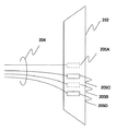
チャネルオフセットさせる磁場もしくは電場に、周期的に変化する磁場もしくは電場を重畳することにより、チャネルオフセットとフライングフォーカルスポットを組み合わせることができる。図3にチャネルオフセットとチャネル方向FFSを組み合わせたときのX線焦点位置を、図2中の陽極202を拡大して示す。電子線偏向手段203から所定の磁場もしくは電場を発生させることにより、X線焦点205AからX線焦点205Bへチャネルオフセットされる。さらに、周期的に変化する磁場もしくは電場を電子線偏向手段203から重畳させることにより、X線焦点205Cと205Dの位置へ交互にシフトされる。
By superimposing a periodically changing magnetic field or electric field on the magnetic field or electric field to be channel offset, the channel offset and the flying focal spot can be combined. FIG. 3 shows the X-ray focal point position when the channel offset and the channel direction FFS are combined, with the
チャネル方向FFS使用時にサンプリング密度を向上させるチャネルオフセット量Doff_ffsは、整数Zを用いて以下のように示される。
The channel offset amount Doff_ffs for improving the sampling density when using the channel direction FFS is expressed as follows using the integer Z.
Doff_ffs=( 2Z + 1 ) / 8 (数2)
(数2)において、Z=0とするとDoff_ffs =0.125となり、チャネル方向FFS使用時のチャネルオフセット量としてはこの値を用いることが好ましい。すなわち、チャネル方向FFSの使用・未使用により好ましいチャネルオフセット量が異なる。また、チャネル方向FFSを使用しチャネルオフセット量を0.125としたときに対向データが存在しない場合や、チャネル方向FFS未使用時にチャネルオフセットを0.125とした場合は、データのサンプリングが等間隔でなくなる。その結果、チャネル方向FFSを使用せずにチャネルオフセット量を0.25とした場合よりも空間分解能が低下する。そこで、設定された撮影条件に応じてチャネルオフセット量を変化させることにより、空間分解能を低下させない撮影が可能となる。
Doff_ffs = (2Z + 1) / 8 (Formula 2)
In (Expression 2), if Z = 0, Doff_ffs = 0.125, and this value is preferably used as the channel offset amount when the channel direction FFS is used. That is, the preferred channel offset amount differs depending on whether or not the channel direction FFS is used. In addition, when the opposite data does not exist when the channel direction FFS is used and the channel offset amount is 0.125, or when the channel offset is 0.125 when the channel direction FFS is not used, data sampling is not evenly spaced. As a result, the spatial resolution is lower than when the channel offset amount is set to 0.25 without using the channel direction FFS. Therefore, by changing the channel offset amount according to the set imaging conditions, it is possible to perform imaging without reducing the spatial resolution.
以下に、本発明に係わるチャネルオフセット量の決定方法について図4〜6を用いて説明する。 The method for determining the channel offset amount according to the present invention will be described below with reference to FIGS.
第1の方法は図4に示すようにチャネル方向FFSが使用される場合にチャネルオフセットを0.125チャネルに設定し、それ以外の場合にはチャネルオフセットを0.25チャネルに設定する。 In the first method, as shown in FIG. 4, when the channel direction FFS is used, the channel offset is set to 0.125 channel, and in other cases, the channel offset is set to 0.25 channel.
第2の方法は図5に示すようにチャネル方向FFSか、チャネル列方向FFSが使用される場合にチャネルオフセットを0.125チャネルに設定し、それ以外の場合にはチャネルオフセットを0.25チャネルに設定する。この場合は、チャネル方向へのFFSが含まれることを意味する。 As shown in FIG. 5, the second method sets the channel offset to 0.125 channel when the channel direction FFS or the channel column direction FFS is used, and sets the channel offset to 0.25 channel otherwise. In this case, it means that FFS in the channel direction is included.
第3の方法は図6に示すようにチャネル方向FFSが使用され、かつ円スキャンまたは、らせんスキャンがローピッチのときにチャネルオフセットを0.125に設定し、それ以外の場合にチャネルオフセットを0.25チャネルに設定する。ここで、ローピッチとは画像再構成に使用できるビュー数が360度以上収集できる場合のらせんピッチである。この場合はチャネル方向FFSが使用され、かつ再構成ビュー幅が1周以上使用できる。 The third method is to set the channel offset to 0.125 when the channel direction FFS is used as shown in Figure 6 and the circular scan or spiral scan is low pitch, otherwise the channel offset is set to 0.25 channel To do. Here, the low pitch is a helical pitch when the number of views that can be used for image reconstruction can be collected over 360 degrees. In this case, the channel direction FFS is used, and the reconstruction view width can be used one or more times.
以下に、本発明に係わる所望のチャネルオフセット量を実現するためのX線焦点位置シフト量について説明する。X線焦点位置シフト量をx(mm)とすると、xは近似的に以下のように表される。 The X-ray focal position shift amount for realizing the desired channel offset amount according to the present invention will be described below. Assuming that the X-ray focal position shift amount is x (mm), x is approximately expressed as follows.
X ≒ c・d・SOD/SDD (数3)
ここで、X線焦点と撮影周回中心との距離をSOD(mm)、X線焦点とX線検出器との距離をSDD(mm)、X線検出器(中心位置)と撮影周回中心との距離をDOD(mm)、検出器素子チャネル方向のサイズをd(mm)、チャネルオフセット量をc(channel)とした。
X ≒ c ・ d ・ SOD / SDD (Equation 3)
Here, the distance between the X-ray focal point and the imaging center is SOD (mm), the distance between the X-ray focal point and the X-ray detector is SDD (mm), and the distance between the X-ray detector (center position) and the imaging center is The distance was DOD (mm), the detector element channel direction size was d (mm), and the channel offset amount was c (channel).
本発明の様々な実施例に関する以上の記述から、本発明の目的が達成されたことは明らかである。本発明を詳細に渡って記述するとともに図示したが、これらは説明及び例示のみを意図したものであって、これらに限定されるものではない。また、本実施の形態では、X線を用いた断層撮影装置を用いているが、これに限定されず、ガンマ線や光を用いた断層撮影装置にも適用可能である。このように、本発明の要旨は、特許請求の範囲によってのみ限定されるものとする。 From the foregoing description of various embodiments of the present invention, it is evident that the objects of the invention are attained. While the present invention has been described and illustrated in detail, they are intended for purposes of illustration and illustration only and are not intended to be limiting. In this embodiment, a tomographic apparatus using X-rays is used, but the present invention is not limited to this, and the present invention can also be applied to a tomographic apparatus using gamma rays or light. Thus, the gist of the present invention is limited only by the claims.
1 X線CT装置、100 スキャンガントリ部、101 X線管、102 回転円盤、103 コリメータ、104 開口部、105 寝台、106 X線検出器、107 データ収集装置、108 ガントリ制御装置、109 寝台制御装置、110 X線制御装置、120 操作卓、121 入力装置、122 画像演算装置、123 記憶装置、124 システム制御装置、125 表示装置、201 陰極、202 陽極、203 電子線偏向手段、204 電子線、205 X線焦点 1 X-ray CT system, 100 scan gantry unit, 101 X-ray tube, 102 rotating disk, 103 collimator, 104 aperture, 105 bed, 106 X-ray detector, 107 data collection device, 108 gantry control device, 109 bed control device , 110 X-ray control device, 120 console, 121 input device, 122 image calculation device, 123 storage device, 124 system control device, 125 display device, 201 cathode, 202 anode, 203 electron beam deflection means, 204 electron beam, 205 X-ray focus
Claims (1)
前記操作卓を介して設定された撮影条件に基づき前記放射線焦点のシフト量を制御する放射線焦点シフト量制御装置と、
をさらに備えていることを特徴とする放射線CT装置。 A radiation source that irradiates the subject with radiation; a radiation detector that is disposed opposite to the radiation source and that detects radiation transmitted through the subject; and the radiation source and the radiation detector are mounted around the subject. A rotating scanner, an image reconstruction device for reconstructing a tomographic image of a subject based on the amount of transmitted radiation detected by the radiation detector, and an image display device for displaying the tomographic image reconstructed by the image reconstruction device; In a radiation CT apparatus comprising: a console used to set imaging conditions for imaging the subject; and a radiation focus shift device that shifts the focal point of the radiation in a rotation direction or a rotation axis direction of the scanner.
A radiation focus shift amount control device that controls the shift amount of the radiation focus based on imaging conditions set via the console;
A radiation CT apparatus further comprising:
Priority Applications (1)
| Application Number | Priority Date | Filing Date | Title |
|---|---|---|---|
| JP2007182934A JP5183988B2 (en) | 2007-07-12 | 2007-07-12 | Radiation CT system |
Applications Claiming Priority (1)
| Application Number | Priority Date | Filing Date | Title |
|---|---|---|---|
| JP2007182934A JP5183988B2 (en) | 2007-07-12 | 2007-07-12 | Radiation CT system |
Publications (3)
| Publication Number | Publication Date |
|---|---|
| JP2009018024A true JP2009018024A (en) | 2009-01-29 |
| JP2009018024A5 JP2009018024A5 (en) | 2010-08-19 |
| JP5183988B2 JP5183988B2 (en) | 2013-04-17 |
Family
ID=40358180
Family Applications (1)
| Application Number | Title | Priority Date | Filing Date |
|---|---|---|---|
| JP2007182934A Expired - Fee Related JP5183988B2 (en) | 2007-07-12 | 2007-07-12 | Radiation CT system |
Country Status (1)
| Country | Link |
|---|---|
| JP (1) | JP5183988B2 (en) |
Cited By (1)
| Publication number | Priority date | Publication date | Assignee | Title |
|---|---|---|---|---|
| JP2019092585A (en) * | 2017-11-17 | 2019-06-20 | キヤノンメディカルシステムズ株式会社 | X-ray CT apparatus and X-ray generation system |
Citations (2)
| Publication number | Priority date | Publication date | Assignee | Title |
|---|---|---|---|---|
| JP2007014783A (en) * | 2005-07-07 | 2007-01-25 | Siemens Ag | Focusing method in computer tomographic apparatus |
| JP2007519461A (en) * | 2004-01-29 | 2007-07-19 | コーニンクレッカ フィリップス エレクトロニクス エヌ ヴィ | Computed tomographic imaging apparatus and method with staggered pixel and focus modulation |
-
2007
- 2007-07-12 JP JP2007182934A patent/JP5183988B2/en not_active Expired - Fee Related
Patent Citations (2)
| Publication number | Priority date | Publication date | Assignee | Title |
|---|---|---|---|---|
| JP2007519461A (en) * | 2004-01-29 | 2007-07-19 | コーニンクレッカ フィリップス エレクトロニクス エヌ ヴィ | Computed tomographic imaging apparatus and method with staggered pixel and focus modulation |
| JP2007014783A (en) * | 2005-07-07 | 2007-01-25 | Siemens Ag | Focusing method in computer tomographic apparatus |
Cited By (2)
| Publication number | Priority date | Publication date | Assignee | Title |
|---|---|---|---|---|
| JP2019092585A (en) * | 2017-11-17 | 2019-06-20 | キヤノンメディカルシステムズ株式会社 | X-ray CT apparatus and X-ray generation system |
| JP7175602B2 (en) | 2017-11-17 | 2022-11-21 | キヤノンメディカルシステムズ株式会社 | X-ray CT device and X-ray generation system |
Also Published As
| Publication number | Publication date |
|---|---|
| JP5183988B2 (en) | 2013-04-17 |
Similar Documents
| Publication | Publication Date | Title |
|---|---|---|
| JP6187298B2 (en) | X-ray imaging system and image processing method | |
| US10082473B2 (en) | X-ray filtration | |
| JP4537129B2 (en) | System for scanning objects in tomosynthesis applications | |
| JP2005080919A (en) | Radiation tomograph apparatus | |
| JP2011218147A (en) | Radiographic system | |
| JP2012120715A (en) | Radiological image detection apparatus, radiographic apparatus and radiographic system | |
| JP2005296651A (en) | Computed tomography system | |
| JP2005087618A (en) | Radiation calculated tomography and radiation detector used therefor | |
| JP2009006133A (en) | X-ray ct apparatus and method of controlling the same | |
| JP2008012206A (en) | X-ray tomographic apparatus | |
| US10524751B2 (en) | Radiographic imaging apparatus | |
| JP6538721B2 (en) | Method of two-color radiography using laser and Compton X-ray source | |
| JP5308862B2 (en) | Medical bed apparatus and medical image photographing apparatus | |
| JP5447526B2 (en) | Radiation imaging apparatus and image acquisition method | |
| CN111031917B (en) | X-ray system and method for operating the same | |
| JP2015208601A (en) | X-ray ct apparatus, image processor, and projection data generation method | |
| JP5498061B2 (en) | X-ray computed tomography system | |
| JP6377615B2 (en) | X-ray CT apparatus and image reconstruction method | |
| JP5183988B2 (en) | Radiation CT system | |
| JP2007282740A (en) | X-ray ct apparatus | |
| JP6365746B2 (en) | Image processing apparatus, X-ray imaging system, and image processing method | |
| JP4381099B2 (en) | Radiation tomography equipment | |
| JP2020103571A (en) | Medical processing device and X-ray diagnostic system | |
| JP2019063509A (en) | Radiodiagnosis device, radiation detector, and collimator | |
| JP6220599B2 (en) | X-ray CT apparatus and projection data upsampling method |
Legal Events
| Date | Code | Title | Description |
|---|---|---|---|
| A521 | Request for written amendment filed |
Free format text: JAPANESE INTERMEDIATE CODE: A523 Effective date: 20100707 |
|
| A621 | Written request for application examination |
Free format text: JAPANESE INTERMEDIATE CODE: A621 Effective date: 20100707 |
|
| A977 | Report on retrieval |
Free format text: JAPANESE INTERMEDIATE CODE: A971007 Effective date: 20120215 |
|
| A131 | Notification of reasons for refusal |
Free format text: JAPANESE INTERMEDIATE CODE: A131 Effective date: 20120305 |
|
| A521 | Request for written amendment filed |
Free format text: JAPANESE INTERMEDIATE CODE: A523 Effective date: 20120427 |
|
| A131 | Notification of reasons for refusal |
Free format text: JAPANESE INTERMEDIATE CODE: A131 Effective date: 20120904 |
|
| A521 | Request for written amendment filed |
Free format text: JAPANESE INTERMEDIATE CODE: A523 Effective date: 20120920 |
|
| TRDD | Decision of grant or rejection written | ||
| A01 | Written decision to grant a patent or to grant a registration (utility model) |
Free format text: JAPANESE INTERMEDIATE CODE: A01 Effective date: 20130107 |
|
| A61 | First payment of annual fees (during grant procedure) |
Free format text: JAPANESE INTERMEDIATE CODE: A61 Effective date: 20130116 |
|
| R150 | Certificate of patent or registration of utility model |
Ref document number: 5183988 Country of ref document: JP Free format text: JAPANESE INTERMEDIATE CODE: R150 Free format text: JAPANESE INTERMEDIATE CODE: R150 |
|
| FPAY | Renewal fee payment (event date is renewal date of database) |
Free format text: PAYMENT UNTIL: 20160125 Year of fee payment: 3 |
|
| S111 | Request for change of ownership or part of ownership |
Free format text: JAPANESE INTERMEDIATE CODE: R313111 |
|
| S533 | Written request for registration of change of name |
Free format text: JAPANESE INTERMEDIATE CODE: R313533 |
|
| R350 | Written notification of registration of transfer |
Free format text: JAPANESE INTERMEDIATE CODE: R350 |
|
| LAPS | Cancellation because of no payment of annual fees |