JP2009014251A - Ventilation device - Google Patents
Ventilation device Download PDFInfo
- Publication number
- JP2009014251A JP2009014251A JP2007175825A JP2007175825A JP2009014251A JP 2009014251 A JP2009014251 A JP 2009014251A JP 2007175825 A JP2007175825 A JP 2007175825A JP 2007175825 A JP2007175825 A JP 2007175825A JP 2009014251 A JP2009014251 A JP 2009014251A
- Authority
- JP
- Japan
- Prior art keywords
- rotational speed
- blower
- differential pressure
- air volume
- trial
- Prior art date
- Legal status (The legal status is an assumption and is not a legal conclusion. Google has not performed a legal analysis and makes no representation as to the accuracy of the status listed.)
- Pending
Links
Images


Classifications
-
- Y—GENERAL TAGGING OF NEW TECHNOLOGICAL DEVELOPMENTS; GENERAL TAGGING OF CROSS-SECTIONAL TECHNOLOGIES SPANNING OVER SEVERAL SECTIONS OF THE IPC; TECHNICAL SUBJECTS COVERED BY FORMER USPC CROSS-REFERENCE ART COLLECTIONS [XRACs] AND DIGESTS
- Y02—TECHNOLOGIES OR APPLICATIONS FOR MITIGATION OR ADAPTATION AGAINST CLIMATE CHANGE
- Y02B—CLIMATE CHANGE MITIGATION TECHNOLOGIES RELATED TO BUILDINGS, e.g. HOUSING, HOUSE APPLIANCES OR RELATED END-USER APPLICATIONS
- Y02B30/00—Energy efficient heating, ventilation or air conditioning [HVAC]
- Y02B30/70—Efficient control or regulation technologies, e.g. for control of refrigerant flow, motor or heating
Landscapes
- Air Conditioning Control Device (AREA)
Abstract
Description
本発明は、例えば、一般住宅や事務所などの複数の部屋、浴室、トイレの換気を1台で行う換気装置などに関わり、換気装置の排気接続口の近傍などに設けたオリフィスなどの前後の差圧により、設置状況によってダクト配置の条件が異なっても、所定の安定した排気風量が得られるようにしたものである。 The present invention relates to, for example, a ventilator that ventilates a plurality of rooms, bathrooms, and toilets such as a general house or office, and the front and rear of an orifice provided in the vicinity of an exhaust connection port of the ventilator. A predetermined stable exhaust air volume can be obtained even if the duct arrangement conditions differ depending on the installation conditions due to the differential pressure.
従来、この種のダクトを有する換気装置は、建物の広さや間取りで給気ダクトや排気ダクトの長さや曲がりなどの設置条件(ダクト抵抗)が異なっても、設置現場において送風機の出力調整などを行わずに自動的に所定量の安定した排気風量が得られることが求められている。安定した排気風量を確保するためには、排気風量を正確に計測するセンサが必要であり、このためのセンサとしてオリフィス式流量計が実用化されており、このセンサの原理を用いた換気装置も提案されている(例えば、特許文献1参照)。 Conventionally, a ventilator with this type of duct adjusts the output of the blower at the installation site even if the installation conditions (duct resistance) such as the length and bending of the air supply and exhaust ducts differ depending on the size and layout of the building. There is a need to automatically obtain a predetermined amount of a stable exhaust air flow without performing the operation. In order to ensure a stable exhaust air volume, a sensor that accurately measures the exhaust air volume is required, and an orifice type flow meter has been put to practical use as a sensor for this purpose, and a ventilator using the principle of this sensor is also available. It has been proposed (see, for example, Patent Document 1).
以下、その換気装置について図12を参照しながら説明する。図に示すように、建物の上部に垂直方向に取り付けられる換気装置120は、中央部にオリフィス(絞り機構)部を有する仕切り板121により上下に二分され、下方にチャンバー122を有する。仕切り板121の上方に風洞123を有し、その上方に送風機124を設けている。さらにその上方に排気ダクト125が取り付け可能なダクト接続口126を有している。風洞123の内部にはギヤードモータ127で駆動され、矢示のように回動して風洞123内の通風断面積を調節する風量調節部材128を設けている。仕切り板121の一部と風洞123の一部とにそれぞれ圧力検出口129、1210を設け、これに接続し、チャンバー122と風洞123内の差圧を測定する差圧センサ1211が設けられている。
Hereinafter, the ventilator will be described with reference to FIG. As shown in the figure, a
このような構成において、差圧センサ1211を入力とする制御手段(図示せず)は、差圧センサ1211が検知する差圧が絶えず一定になるようにギヤードモータ127を駆動するので、給気ダクトや排気ダクトの条件が異なっても、あるいは外気圧が変動しても所定量の排気風量が確保できる。
このような差圧センサによる風量制御方式は、建物の広さや間取りで給気ダクトや排気ダクトの長さや曲がりなどの設置条件(ダクト抵抗)が異なっても、設置現場において送風機の出力調整などを行わずに自動的に所定量の安定した排気風量が得られることから換気装置に搭載されることが多くなっている。しかしながら、風量は測定装置を用いて測定しなければ知ることができず、粉塵、結露、差圧センサの故障等の影響で所定の換気風量が出ていなくても使用者は気づかないという課題がある。本発明は、このような課題を解決し換気風量が長期に渡り正確度を維持できる換気装置の提供を目的としている。 The air volume control method using differential pressure sensors adjusts the output of the blower at the installation site even if the installation conditions (duct resistance) such as the length and bending of the air supply and exhaust ducts vary depending on the size and layout of the building. Since a predetermined amount of stable exhaust air volume can be automatically obtained without performing the operation, it is often mounted on a ventilator. However, there is a problem that the air volume cannot be known unless it is measured using a measuring device, and the user does not notice even if the predetermined ventilation air volume is not emitted due to the influence of dust, condensation, differential pressure sensor failure, etc. is there. An object of the present invention is to provide a ventilator capable of solving such problems and maintaining the accuracy of ventilation airflow over a long period of time.
本発明の換気装置は上記目的を達成するために、風量設定部と、試運転スイッチと、空気を送風する送風機と、前記送風機の排気側にオリフィスと、前記オリフィスの風上側と風下側の差圧を検知する差圧検知部と前記送風機の回転数を検知する回転数検知手段と前記送風機の回転数を可変する回転数可変手段と記憶手段とを備えた換気装置において、前記制御部は前記試運転スイッチにより試運転を開始し、前記差圧検知部が検知する差圧を所定値になるように前記回転数可変手段を介して送風機の回転数を制御して排気を行い前記送風機の回転数安定後の回転数を前記記憶手段に記憶し、試運転を終了し、前記制御手段は、その内部に前記記憶手段に記憶した送風機の回転数と前記風量設定部より設定される風量に対応する回転数との相関データを保有し、前記回転数検知手段が検知する回転数が前記相関データと一致するように前記回転数可変手段を介して送風機の回転数を制御するものであり、オリフィスの風上側と風下側の差圧、すなわち絞り機構の一例のオリフィス前後の差圧を検知する差圧センサを備え、この状態において、給気ダクトや排気ダクトのダクト抵抗を変えて差圧センサが検知する差圧値が試運転時における所定値が得られる送風機の回転数とそのダクトの状態において風量設定部により設定可能な風量で運転している時の回転数のデータを実験的に求め、このデータを予め制御手段内の記憶装置に内蔵し、実際の運転状態においては、前記記憶手段に記憶した試運転時の回転数データから前記の記憶装置内のデータより目標となる回転数を求め、送風機の回転数が一致するようにして排気を行うようにしたものである。 In order to achieve the above object, the ventilator of the present invention has an air volume setting unit, a trial operation switch, a blower for blowing air, an orifice on the exhaust side of the blower, and a differential pressure between the windward side and the leeward side of the orifice. In the ventilator comprising a differential pressure detection unit for detecting the rotational speed, a rotational speed detection means for detecting the rotational speed of the blower, a rotational speed variable means for varying the rotational speed of the blower, and a storage means, the control unit is configured to perform the trial operation. A trial run is started by the switch, and after the rotational speed of the blower is stabilized by controlling the rotational speed of the blower via the rotational speed variable means so that the differential pressure detected by the differential pressure detection unit becomes a predetermined value. Is stored in the storage means, the trial operation is terminated, and the control means includes the rotation speed of the blower stored in the storage means and the rotation speed corresponding to the air volume set by the air volume setting unit. Phase of Holding the data and controlling the rotational speed of the blower via the rotational speed variable means so that the rotational speed detected by the rotational speed detection means coincides with the correlation data. In this state, the differential pressure value detected by the differential pressure sensor is changed by changing the duct resistance of the air supply duct or exhaust duct. Data on the rotational speed of the blower at which a predetermined value is obtained during the trial operation and the rotational speed when operating with the air volume settable by the air volume setting unit in the state of the duct are experimentally obtained, and this data is previously stored in the control means. In the actual operation state, the target rotational speed is obtained from the data in the storage device from the rotational speed data stored in the storage means during the trial operation, As speed match is obtained to perform the exhaust.
この手段により建物の広さや間取りで給気ダクトや排気ダクトの長さや曲がりなど配置条件(ダクト抵抗)が異なっても、設置現場において送風機の出力調整などを行わずに自動的に所定量の安定した排気風量が得られる。 By this means, even if the arrangement conditions (duct resistance) such as the length and bend of the air supply duct and exhaust duct differ depending on the size and layout of the building, it automatically stabilizes the specified amount without adjusting the blower output at the installation site. The exhaust air volume can be obtained.
本発明の換気装置は上記目的を達成するために、前記試運転が終了していない場合、送風機を起動しないようにしたものである。 In order to achieve the above object, the ventilator of the present invention is configured such that the blower is not started when the trial operation is not completed.
本発明の換気装置は上記目的を達成するために、前記試運転が終了していない場合、所定の回転数で送風機の運転を行うようにしたものである。 In order to achieve the above object, the ventilator of the present invention is configured to operate the blower at a predetermined rotational speed when the trial operation is not completed.
本発明の換気装置は上記目的を達成するために、前記試運転が終了していない場合、送風機を起動しないか、所定の回転数で送風機の運転を行うか切換えられるようにしたものである。 In order to achieve the above object, the ventilator of the present invention is configured such that when the trial operation is not completed, the blower is not started or the blower is operated at a predetermined number of revolutions.
本発明の換気装置は上記目的を達成するために、前記試運転時に前記回転数検知手段が検知する回転数が所定の範囲外となることが所定時間継続したことをもって異常と判定し、報知音もしくは表示により異常が発生したことを使用者に報知するようにしたものである。 In order to achieve the above object, the ventilator of the present invention determines that there is an abnormality when the rotation speed detected by the rotation speed detection means during the trial operation is outside a predetermined range for a predetermined period of time, The display notifies the user that an abnormality has occurred.
本発明によれば、粉塵、結露等の影響を受けず換気風量が長期に渡り正確度を維持できる換気装置を提供できる。 ADVANTAGE OF THE INVENTION According to this invention, the ventilation apparatus which can maintain a precision over a long period of ventilation airflow without being influenced by dust, dew condensation, etc. can be provided.
本発明の請求項1記載の発明は、風量設定部と、試運転スイッチと、空気を送風する送風機と、前記送風機の排気側にオリフィスと、前記オリフィスの風上側と風下側の差圧を検知する差圧検知部と前記送風機の回転数を検知する回転数検知手段と前記送風機の回転数を可変する回転数可変手段と記憶手段とを備えた換気装置において、前記制御部は前記試運転スイッチにより試運転を開始し、前記差圧検知部が検知する差圧を所定値になるように前記回転数可変手段を介して送風機の回転数を制御して排気を行い、前記送風機の回転数安定後の回転数を前記記憶手段に記憶し、試運転を終了し、前記制御手段は、その内部に前記記憶手段に記憶した送風機の回転数と前記風量設定部より設定される風量に対応する回転数との相関データを保有し、前記回転数検知手段が検知する回転数が前記相関データと一致するように前記回転数可変手段を介して送風機の回転数を制御することを特徴とする換気装置である。このことにより、試運転時に記憶した回転数とこの回転数に対応する風量との相関データより回転数を制御しているので、粉塵、結露等の影響を受けず換気風量が長期に渡り正確度を維持できる換気装置を提供できる。
The invention according to
本発明の請求項2記載の発明は、試運転が終了していない場合、送風機を起動しないようにしたことを特徴とする換気装置である。このことにより、試運転を終了しないと送風機が起動しないため試運転の実施を確実に実行させることができる換気装置を提供できる。
The invention described in
本発明の請求項3記載の発明は、試運転が終了していない場合、所定の回転数で送風機の運転を行うことを特徴とする換気装置である。このことにより、試運転を終了していなくても簡易的に換気できる換気装置を提供できる。
The invention according to
本発明の請求項4記載の発明は、試運転が終了していない場合、送風機を起動しないか、所定の回転数で送風機の運転を行うか切換えられることを特徴とする換気装置である。このことにより、試運転を終了していない場合における送風機の駆動の有無を使途に応じて設定可能な換気装置を提供できる。 According to a fourth aspect of the present invention, there is provided a ventilator characterized in that when the trial run is not completed, the blower is not started or the blower is operated at a predetermined rotational speed. Thus, it is possible to provide a ventilator that can set whether or not the blower is driven when the trial run is not finished, depending on the purpose of use.
本発明の請求項5記載の発明は、試運転時に前記回転数検知手段が検知する回転数が所定の範囲外となることが所定時間継続したことをもって異常と判定し、報知音もしくは表示により異常が発生したことを使用者に報知することを特徴とする換気装置である。このことにより、本発明によれば簡単な構成で、換気風量が所定の風量にならない場合に迅速に使用者に知らせる換気装置を提供できる。
In the invention according to
(実施の形態1)
図1は本実施の形態1の換気装置の外観を示す図であり、図2は同差圧検知部の詳細を示す図である。
(Embodiment 1)
FIG. 1 is a diagram showing the appearance of the ventilator according to the first embodiment, and FIG. 2 is a diagram showing details of the differential pressure detector.
換気装置1は、例えば、給気ダクト(図示せず)を接続するための複数個のダクト接続口2を有し、他方に排気ダクト(図示せず)を接続するための1個の排気ダクト接続口3を送風機13の排気側に備え、この排気ダクト接続口3の外壁に差圧検知部4を装備している。排気ダクト接続口3の内部に設けたオリフィス5の両側の外壁に設けたオリフィス5の風上側の圧力検出口6およびオリフィス5の風下側の圧力検出口7に係合して、オリフィス5の風上側と風下側の差圧、すなわちオリフィス5の前後の差圧を検知する差圧センサ8を設けている。ここでは、オリフィス5を排気ダクト接続口3の内部に設けたが、これに限定されるものでなく、送風機13の排気側の換気装置に備えればよく、また、排気ダクト接続口3の近傍に設けてもよい。
The
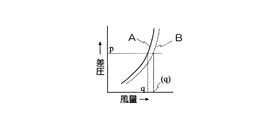
図3は、換気運転時の風量と差圧センサ8が検知する差圧の関係を示す図である。
FIG. 3 is a diagram showing the relationship between the air volume during the ventilation operation and the differential pressure detected by the
オリフィス式の流量測定は、前述のような断面均一な気流が得られる場合には風量の二乗に比例した差圧を示す特性を有する。これは風量を一定に保つためには差圧が一定になるように送風機13の回転数を制御すれば良いことを示すものである。特性Aは、設計標準として設定したダクト配管のモデルにおける特性を示すもので、この特性を利用して、例えば差圧をpになるように送風機の回転数を制御すれば風量q0で定風量の排気運転ができる。また、管理する差圧を変えることで風量の調節が可能である。しかしながら、差圧センサ8が、使用環境により粉塵や結露の影響を受ける場合があり特性Aとのずれから風量を一定にたもてない場合が生じる。これを解決するためには定期的なメンテナンスを行うようにすれば修正できるが、利便性が著しく低下する。本発明は、この課題を解決するものである。
The orifice type flow rate measurement has a characteristic of showing a differential pressure proportional to the square of the air volume when an air flow having a uniform cross section as described above is obtained. This indicates that the rotational speed of the
図4は、本実施の形態1の換気装置の電気系の構成を示す図である。 FIG. 4 is a diagram illustrating a configuration of an electric system of the ventilation device according to the first embodiment.
主としてCPUで構成され記憶装置9aを保有する制御手段9は、入力部に前述の差圧センサ8を接続するとともに、送風機の回転数を検知する回転数検知手段10と風量設定部11と試運転スイッチ12とを接続し、出力側に送風機13の回転数を制御する回転数可変手段14を接続し、また記憶手段15を接続している。回転数検知手段10は、例えば送風機の回転軸に装着した磁石とこれと対向するように設けたホール素子で構成したもの、あるいは光学式のものである。回転数可変手段14は、例えば、送風機のモータがブラシレスDCモータの場合は、外部信号で出力電圧が調節できる可変電圧電源装置などである。記憶手段15は、例えば、EEPROMなどである。差圧検知部4としては、差圧が計測できればよく、例えば、静電方式の差圧センサなどがある。
The control means 9 mainly composed of a CPU and having a
図5は、制御手段9の記憶装置9aに内蔵されるデータを説明するための図である。
FIG. 5 is a diagram for explaining data built in the
図5(a)は、送風機13の回転数を一定にした時の、静圧と排気ダクト接続口3から排気される風量との関係とダクト抵抗曲線を示す図である。あるダクト抵抗において任意の風量を確保するための回転数は一意に決まる。すなわち、ある風量における送風機13の回転数からダクト抵抗を求めることができることを示している。 図5(b)特性Aは、差圧センサ8が検知する差圧を試運転時の所定値になるようにした時のダクト抵抗と送風機13の回転数を示す図である。特性B、特性Cは風量設定部11により設定される風量を一定にした時のダクト抵抗と送風機13の回転数を示す図である。このデータは、実験室において、各種のダクト配管のモデルを設定し、正確な流量が測定できる流量計を用いて、例えば特性Aの場合は差圧センサ8が検知する差圧が試運転時の所定値Pになるように送風機13の回転数を調節し、特性Bは流量計の計測値が毎時150立方米になるよう送風機13の回転数を調節し、特性Cは流量計の計測値が毎時100立方米になるよう送風機13の回転数を調節し送風機13の回転数を求めたものである。すなわち、試運転時の送風機13の回転数がraの時、毎時150立方米にするには送風機13の回転数をrbに、毎時100立方米にするには送風機13の回転数をrcにすればよいことを示している。この図5(b)のデータは、データテーブルの形態か、回転数の相関式の形態で記憶装置9aに記憶されている。
FIG. 5A is a diagram showing the relationship between the static pressure and the amount of air exhausted from the exhaust
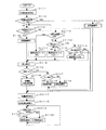
次に、図4〜図5を参照しながら図6を用い、図6のステップ順序に従って制御手段9の制御動作を説明する。図6は制御手段9の制御動作を説明するためのフローチャートである。なお、説明を解りやすくするため、送風機の目標風量は数字を例示して説明する。 Next, the control operation of the control means 9 will be described in accordance with the step order of FIG. 6 using FIG. 6 with reference to FIGS. FIG. 6 is a flowchart for explaining the control operation of the control means 9. In addition, in order to make explanation easy to understand, the target air volume of the blower will be described by exemplifying numerals.
ステップ(以下S)61において、記憶手段15より試運転回転数を読み込みS62にて試運転回転数データの有無を判定し無しの場合、S63に移行して試運転スイッチ12がONするまで待機する。試運転スイッチ12がONするとS64へ移行して送風機13を運転する。次にS65にて差圧センサ8の値を読取る。S66へ移行して差圧センサ8が検知する差圧と試運転時の所定値Pを比較し異なる場合はS67へ移行する。S67にて差圧センサ8が検知する差圧が試運転時の所定値Pより低い場合はS68へ移行してS68にて回転数可変手段14により回転数を増加させる。
In step (hereinafter referred to as S) 61, the trial operation rotational speed is read from the storage means 15, and if it is not determined in S62 whether or not there is trial operation rotational speed data, the process proceeds to S63 and waits until the
S67にて差圧センサ8が検知する差圧が試運転時の所定値Pより高い場合はS69へ移行してS69にて回転数可変手段14により回転数を減少させる。S68およびS69にて回転数を可変させた後、S65に移行しS66にて差圧センサ8が検知する差圧と試運転時の所定値Pを比較し一致するまでS65〜S69の動作を繰り返す。S66にて差圧センサ8が検知する差圧と試運転時の所定値Pを比較し一致するとS610に移行し回転数検出手段10により検知した試運転回転数raを記憶手段15に記憶し、S611へ移行する。S611にて風量設定部11により目標風量(150立方米または100立方米)を決定する。次にS612にて試運転回転数raと図5(b)により記憶装置9aに記憶したデータテーブルから目標風量(150立方米または100立方米)に応じた目標回転数(rbまたはrc)を決定する。
If the differential pressure detected by the
S613にて目標回転数と回転数検出手段10により検知した回転数を比較し目標回転数>回転数の場合S614に移行して回転数可変手段14により回転数を増加させる。S613にて目標回転数<回転数の場合、S615に移行して回転数可変手段14により回転数を減少させ、その後S613〜S615を繰り返す。また、S62にて試運転回転数データがすでに有の場合、S616にて送風機13を運転しS611に移行する。S611にて風量設定部11により目標風量を決定し、S612にて試運転回転数raと図5(b)により記憶装置9aに記憶したデータテーブルから目標風量に応じた目標回転数を決定する。その後S613〜S615を繰り返す。
In step S613, the target rotational speed is compared with the rotational speed detected by the rotational
以上説明したように本発明の換気装置は、試運転時に記憶した回転数とこの回転数に対応する風量との相関データより回転数を制御しているので、粉塵、結露等の影響を受けず換気風量が長期に渡り正確度を維持でき、試運転が終了していない場合、送風機を起動しないため試運転の実施を確実に実行させることができる換気装置を提供できる。 As described above, the ventilator of the present invention controls the rotational speed based on the correlation data between the rotational speed stored during the trial operation and the air volume corresponding to this rotational speed, and therefore is not affected by dust, condensation, etc. When the airflow can maintain accuracy over a long period of time and the trial run is not finished, the blower is not started, and thus the ventilator can be provided that can reliably perform the trial run.
(実施の形態2)
本実施の形態の全体構成は、実施の形態1の構成に同じであり、説明を省略する。
(Embodiment 2)
The overall configuration of the present embodiment is the same as that of the first embodiment, and a description thereof is omitted.
次に、図4〜図5を参照しながら図7を用い、図7のステップ順序に従って制御手段9の制御動作を説明する。図7は制御手段9の制御動作を説明するためのフローチャートである。 Next, the control operation of the control means 9 will be described in accordance with the step order of FIG. 7 using FIG. 7 with reference to FIGS. FIG. 7 is a flowchart for explaining the control operation of the control means 9.
まずS71において、記憶手段15より試運転回転数を読み込みS72にて試運転回転数データの有無を判定し有の場合、S73に移行して風量設定部11により目標風量(150立方米または100立方米)を決定する。次にS74にて試運転回転数raと図5(b)により記憶装置9aに記憶したデータテーブルから目標風量(150立方米または100立方米)に応じた目標回転数(rbまたはrc)を決定する。また、S72にて試運転回転数データが無しの場合、S75に移行して予め決定した任意の回転数より目標回転数を決定する。次にS76にて送風機13を運転しS77に移行する。S77にて目標回転数と回転数検出手段10により検知した回転数を比較し目標回転数>回転数の場合S78に移行して回転数可変手段14により回転数を増加させる。
First, in S71, the trial operation rotational speed is read from the storage means 15, and in S72, the presence or absence of the trial operation rotational speed data is determined. If yes, the process proceeds to S73 and the air
S77にて目標回転数<回転数の場合、S79に移行して回転数可変手段14により回転数を減少させS710へ移行する。S710にて試運転スイッチ12を判定しONするまでS77〜S79を繰り返す。S710にて試運転スイッチ12がONの場合、S711に移行して差圧センサ8の値を読取る。S712へ移行して差圧センサ8が検知する差圧と試運転時の所定値Pを比較し異なる場合はS713へ移行する。S713にて差圧センサ8が検知する差圧が試運転時の所定値Pより低い場合はS714へ移行して回転数可変手段14により回転数を増加させる。S713にて差圧センサ8が検知する差圧が試運転時の所定値Pより高い場合はS715へ移行して回転数可変手段14により回転数を減少させる。S714およびS715にて回転数を可変させた後、S711に移行しS712にて差圧センサ8が検知する差圧と試運転時の所定値Pを比較し一致するまでS711〜S715の動作を繰り返す。
If the target rotational speed is smaller than the rotational speed at S77, the routine proceeds to S79, where the rotational speed is decreased by the rotational speed varying means 14, and the routine proceeds to S710. S77 to S79 are repeated until the
S712にて差圧センサ8が検知する差圧と試運転時の所定値Pを比較し一致するとS716に移行し回転数検知手段10により検知した試運転回転数raを記憶手段15に記憶し、S73へ移行する。
When the differential pressure detected by the
以上説明したように本発明の換気装置は、試運転時に記憶した回転数とこの回転数に対応する風量との相関データより回転数を制御しているので、粉塵、結露等の影響を受けず換気風量が長期に渡り正確度を維持でき、試運転が終了していない場合、送風機を任意の回転数で運転させることができる換気装置を提供できる。 As described above, the ventilator of the present invention controls the rotational speed based on the correlation data between the rotational speed stored during the trial operation and the air volume corresponding to this rotational speed, and therefore is not affected by dust, condensation, etc. When the airflow can maintain accuracy over a long period of time and the trial run is not completed, a ventilator capable of operating the blower at an arbitrary number of rotations can be provided.
(実施の形態3)
本実施の形態の構成の概要は、実施の形態1の構成に同じであり、説明を省略する。
(Embodiment 3)
The outline of the configuration of the present embodiment is the same as that of the first embodiment, and a description thereof will be omitted.
図8は本実施の形態の換気装置の電気系の構成を示す図である。制御手段9であるCPUは試運転が終了していない場合、送風機を起動しないか、所定の回転数で送風機の運転を行うかを切換えられる切換え手段16とで構成されている。なお図4と同じ符号のものは同じ機能を有するものなので説明を省略する。 FIG. 8 is a diagram showing the configuration of the electrical system of the ventilation device of the present embodiment. The CPU which is the control means 9 is constituted by a switching means 16 which can switch whether the blower is not started or the blower is operated at a predetermined rotational speed when the trial operation is not completed. Note that the same reference numerals as those in FIG. 4 have the same functions, and thus description thereof is omitted.
次に、図5および図8を参照しながら図9を用い、図9のステップ順序に従って制御手段9の制御動作を説明する。図9は制御手段9の制御動作を説明するためのフローチャートである。 Next, the control operation of the control means 9 will be described in accordance with the step order of FIG. 9, using FIG. 9 with reference to FIGS. FIG. 9 is a flowchart for explaining the control operation of the control means 9.
まずS91において、記憶手段15より試運転回転数を読み込みS92にて試運転回転数データの有無を判定し無しの場合、S93に移行して切換え手段16にてA(試運転が終了していない場合送風機を運転させない設定)またはB(試運転が終了していない場合、任意の回転数で送風機を運転する設定)を判定しA(試運転が終了していない場合送風機を運転させない設定)の場合、S94に移行し試運転スイッチ12を判定しONするまで待機する。S94にて試運転スイッチ12がONされるとS95へ移行し送風機13を運転し試運転を開始する。次にS96にて差圧センサ8の値を読取る。
First, in S91, the test rotation speed is read from the storage means 15, and if it is not determined in S92 whether the test rotation speed data is present or not, the process proceeds to S93 and the switching means 16 selects A (if the test run has not ended, the blower is turned on). If it is A (setting not to run the blower if the trial run is not completed) or B (setting to run the blower at an arbitrary number of revolutions if the trial run is not finished) and A (setting to not run the blower if the trial run is not finished), the process proceeds to S94 The
S97へ移行して差圧センサ8が検知する差圧と試運転時の所定値Pを比較し異なる場合はS98へ移行する。S98にて差圧センサ8が検知する差圧が試運転時の所定値Pより低い場合はS99へ移行して回転数可変手段14により回転数を増加させる。S98にて差圧センサ8が検知する差圧が試運転時の所定値Pより高い場合はS910へ移行して回転数可変手段14により回転数を減少させる。S99およびS910にて回転数を可変させた後、S96に移行しS97にて差圧センサ8が検知する差圧と試運転時の所定値Pを比較し一致するまでS96〜S910の動作を繰り返す。S97にて差圧センサ8が検知する差圧と試運転時の所定値Pを比較し一致するとS911に移行し回転数検出手段10により検知した試運転回転数raを記憶手段15に記憶し、S912へ移行する。S912では風量設定部11により目標風量(150立方米または100立方米)を決定する。次にS913にて試運転回転数raと図5(b)により記憶装置9aに記憶したデータテーブルから目標風量(150立方米または100立方米)に応じた目標回転数(rbまたはrc)を決定する。
When the process proceeds to S97 and the differential pressure detected by the
その後、S914へ移行し目標回転数と回転数検出手段10により検知した回転数を比較し目標回転数>回転数の場合S915に移行して回転数可変手段14により回転数を増加させる。S914にて目標回転数<回転数の場合、S916に移行して回転数可変手段14により回転数を減少させる。S915およびS916にて回転数を可変した後S917へ移行する。S917にて試運転スイッチ12を判定しONするまでS914〜S917を繰り返す。S917にて試運転スイッチ12がONの場合、S96へ移行し再度、試運転を開始する。試運転開始後の動作は上記と同様の制御動作となるため省略する。S93において切換え手段16にてA(試運転が終了していない場合送風機を運転させない設定)またはB(試運転が終了していない場合、任意の回転数で送風機を運転する設定)を判定しB(試運転が終了していない場合、任意の回転数で送風機を運転する設定)の場合、S918へ移行し予め決定した任意の回転数より目標回転数を決定する。
Thereafter, the process proceeds to S914, where the target rotational speed and the rotational speed detected by the rotational speed detection means 10 are compared, and when the target rotational speed> the rotational speed, the process proceeds to S915 and the rotational speed variable means 14 increases the rotational speed. When the target rotational speed is smaller than the rotational speed in S914, the process proceeds to S916 and the rotational speed is decreased by the rotational
次にS919にて送風機13を運転しS914に移行する。S914移行後の動作は上記と同様の制御動作となるため省略する。S92にて試運転回転数データの有無を判定し有の場合、S920に移行して風量設定部11により目標風量(150立方米または100立方米)を決定する。次にS921にて試運転回転数raと図5(b)により記憶装置9aに記憶したデータテーブルから目標風量(150立方米または100立方米)に応じた目標回転数(rbまたはrc)を決定する。次にS919にて送風機13を運転しS914に移行する。S914移行後の動作は上記と同様の制御動作となるため省略する。
Next, the
以上説明したように本発明の換気装置は、試運転時に記憶した回転数とこの回転数に対応する風量との相関データより回転数を制御しているので、粉塵、結露等の影響を受けず換気風量が長期に渡り正確度を維持でき、試運転が終了していない場合、送風機の起動の有無を選択できる換気装置を提供できる。 As described above, the ventilator of the present invention controls the rotational speed based on the correlation data between the rotational speed stored during the trial operation and the air volume corresponding to this rotational speed, and therefore is not affected by dust, condensation, etc. It is possible to provide a ventilator that can maintain accuracy over a long period of time and can select whether or not the blower is activated when the trial run is not completed.
(実施の形態4)
本実施の形態の構成の概要は、実施の形態1の構成に同じであり、説明を省略する。
(Embodiment 4)
The outline of the configuration of the present embodiment is the same as that of the first embodiment, and a description thereof will be omitted.
図10は本実施の形態の換気装置の電気系の構成を示す図である。制御手段9であるCPUは異常表示手段17(LEDなど)とで構成されている。なお図4と同じ符号のものは同じ機能を有するものなので説明を省略する。 FIG. 10 is a diagram showing the configuration of the electrical system of the ventilation device of the present embodiment. The CPU which is the control means 9 is composed of an abnormality display means 17 (LED or the like). Note that the same reference numerals as those in FIG. 4 have the same functions, and thus description thereof is omitted.
次に、図5および図10を参照しながら図11を用い、図11のステップ順序に従って制御手段9の制御動作を説明する。図11は制御手段9の制御動作を説明するためのフローチャートである。 Next, the control operation of the control means 9 will be described in accordance with the step order of FIG. 11 using FIG. 11 with reference to FIG. 5 and FIG. FIG. 11 is a flowchart for explaining the control operation of the control means 9.
S111において、記憶手段15より試運転回転数を読み込みS112にて試運転回転数データの有無を判定し無しの場合、S113に移行して試運転スイッチ12がONするまで待機する。試運転スイッチ12がONするとS114へ移行して送風機13を運転し試運転を開始する。次にS115にて差圧センサ8の値を読取る。S116へ移行して差圧センサ8が検知する差圧と試運転時の所定値Pを比較し異なる場合はS117へ移行する。S117にて差圧センサ8が検知する差圧が試運転時の所定値Pより低い場合はS118へ移行してS118にて回転数可変手段14により回転数を増加させる。
In S111, the test operation rotational speed is read from the storage means 15, and if it is not determined in S112 whether the test operation rotational speed data is present, the process proceeds to S113 and waits until the
S117にて差圧センサ8が検知する差圧が試運転時の所定値Pより高い場合はS119へ移行してS119にて回転数可変手段14により回転数を減少させる。S118およびS119にて回転数を可変させた後、S1110に移行する。S1110において回転数検出手段10により検知した回転数が試運転時における所定の値の範囲内の場合、S1111に移行し異常検知タイマを停止する。S1110にて回転数検出手段10により検知した回転数が試運転時における所定の値の範囲外の場合S1112へ移行する。S1112にて異常検知タイマが実行していなければS1113へ移行し異常検知タイマをスタートする。S1112にて異常検知タイマが実行していればS1114へ移行し異常検知タイマの経過を判断しタイムアップした場合S1115へ移行し異常表示手段17により異常表示をONする。
When the differential pressure detected by the
以上の動作により試運転時に回転数検知手段が検知する回転数が所定の範囲外となることが所定時間継続したことをもって異常表示することにより使用者に対して故障を報知することができる。S1110〜S1115の制御動作後、S115へ移行し試運転動差を継続する。S116にて差圧センサ8が検知する差圧と試運転時の所定値Pを比較し一致するまでS115〜S1115を繰り返し、S116にて差圧センサ8が検知する差圧と試運転時の所定値Pを比較し一致するとS1116へ移行し回転数検出手段10により検知した試運転回転数raを記憶手段15に記憶し、S1117へ移行する。S1117にて風量設定部11により目標風量(150立方米または100立方米)を決定する。次にS1118にて試運転回転数raと図5(b)により記憶装置9aに記憶したデータテーブルから目標風量(150立方米または100立方米)に応じた目標回転数(rbまたはrc)を決定する。
With the above operation, the failure can be notified to the user by displaying an abnormality when the rotation speed detected by the rotation speed detection means during the trial run is outside the predetermined range for a predetermined time. After the control operation of S1110 to S1115, the process proceeds to S115, and the trial run difference is continued. The differential pressure detected by the
次にS1119にて目標回転数と回転数検出手段10により検知した回転数を比較し目標回転数>回転数の場合S1120に移行して回転数可変手段14により回転数を増加させる。S1119にて目標回転数<回転数の場合、S1121に移行して回転数可変手段14により回転数を減少させ、S1119〜S1121を繰り返す。
Next, in step S1119, the target rotational speed is compared with the rotational speed detected by the rotational
また、S112にて試運転回転数データがすでに有の場合、S1122にて送風機13を運転しS1117に移行する。S1117にて風量設定部11により目標風量を決定し、S1118にて試運転回転数raと図5(b)により記憶装置9aに記憶したデータテーブルから目標風量に応じた目標回転数を決定する。その後、S1119〜S1121を繰り返す。
If the trial run speed data is already present in S112, the
以上説明したように本発明の換気装置は、試運転時に回転数検知手段が検知する回転数が所定の範囲外となることが所定時間継続したことをもって異常と判定し、報知音もしくは表示により異常が発生したことを迅速に使用者に知らせる換気装置を提供できる。 As described above, the ventilator of the present invention determines that an abnormality is detected when the rotation speed detected by the rotation speed detection means during a trial run is outside the predetermined range for a predetermined time, and the abnormality is detected by a notification sound or display. It is possible to provide a ventilation device that promptly informs the user of the occurrence.
本発明によれば粉塵、結露等の影響を受けず換気風量が長期に渡り正確度を維持できるので様々な用途の換気装置に適用できる。 According to the present invention, the accuracy of the ventilation airflow can be maintained over a long period without being affected by dust, condensation, etc., so that the present invention can be applied to a ventilator for various purposes.
1 換気装置
3 排気ダクト接続口
4 差圧検知部
5 オリフィス
8 差圧センサ
9 制御手段
9a 記憶装置
10 回転数検知手段
11 風量設定部
12 試運転スイッチ
13 送風機
14 回転数可変手段
15 記憶手段
16 切換え手段
17 異常表示手段
DESCRIPTION OF
Claims (5)
Priority Applications (1)
| Application Number | Priority Date | Filing Date | Title |
|---|---|---|---|
| JP2007175825A JP2009014251A (en) | 2007-07-04 | 2007-07-04 | Ventilation device |
Applications Claiming Priority (1)
| Application Number | Priority Date | Filing Date | Title |
|---|---|---|---|
| JP2007175825A JP2009014251A (en) | 2007-07-04 | 2007-07-04 | Ventilation device |
Publications (1)
| Publication Number | Publication Date |
|---|---|
| JP2009014251A true JP2009014251A (en) | 2009-01-22 |
Family
ID=40355365
Family Applications (1)
| Application Number | Title | Priority Date | Filing Date |
|---|---|---|---|
| JP2007175825A Pending JP2009014251A (en) | 2007-07-04 | 2007-07-04 | Ventilation device |
Country Status (1)
| Country | Link |
|---|---|
| JP (1) | JP2009014251A (en) |
Cited By (7)
| Publication number | Priority date | Publication date | Assignee | Title |
|---|---|---|---|---|
| JP2010243007A (en) * | 2009-04-02 | 2010-10-28 | Mitsubishi Electric Corp | Air conditioner |
| JP2011012927A (en) * | 2009-07-03 | 2011-01-20 | Fujitsu General Ltd | Control device for fluid delivery device |
| JP2014190651A (en) * | 2013-03-28 | 2014-10-06 | Toto Ltd | Ventilation device |
| JP2016042018A (en) * | 2014-08-15 | 2016-03-31 | 台達電子工業股▲ふん▼有限公司Delta Electronics,Inc. | Control method of air-conditioning facility |
| CN109812935A (en) * | 2019-01-29 | 2019-05-28 | 广东美的暖通设备有限公司 | Air conditioner, the control method of air conditioner and storage medium |
| CN110220267A (en) * | 2018-03-01 | 2019-09-10 | 维谛技术有限公司 | The fan operation method and device of air-conditioner set, air-conditioning system and air-conditioner set |
| WO2020059378A1 (en) * | 2018-09-20 | 2020-03-26 | ダイキン工業株式会社 | Air conditioning device and method for controlling rotation speed of blower fan |
-
2007
- 2007-07-04 JP JP2007175825A patent/JP2009014251A/en active Pending
Cited By (11)
| Publication number | Priority date | Publication date | Assignee | Title |
|---|---|---|---|---|
| JP2010243007A (en) * | 2009-04-02 | 2010-10-28 | Mitsubishi Electric Corp | Air conditioner |
| JP2011012927A (en) * | 2009-07-03 | 2011-01-20 | Fujitsu General Ltd | Control device for fluid delivery device |
| JP2014190651A (en) * | 2013-03-28 | 2014-10-06 | Toto Ltd | Ventilation device |
| JP2016042018A (en) * | 2014-08-15 | 2016-03-31 | 台達電子工業股▲ふん▼有限公司Delta Electronics,Inc. | Control method of air-conditioning facility |
| CN110220267A (en) * | 2018-03-01 | 2019-09-10 | 维谛技术有限公司 | The fan operation method and device of air-conditioner set, air-conditioning system and air-conditioner set |
| CN110220267B (en) * | 2018-03-01 | 2022-01-11 | 维谛技术有限公司 | Air conditioning unit, air conditioning system and fan operation method and device of air conditioning unit |
| WO2020059378A1 (en) * | 2018-09-20 | 2020-03-26 | ダイキン工業株式会社 | Air conditioning device and method for controlling rotation speed of blower fan |
| JP2020046135A (en) * | 2018-09-20 | 2020-03-26 | ダイキン工業株式会社 | Air conditioning device and rotational speed adjustment method for blower fan |
| CN112739958A (en) * | 2018-09-20 | 2021-04-30 | 大金工业株式会社 | Air conditioner and method for adjusting rotation speed of blower fan |
| CN112739958B (en) * | 2018-09-20 | 2022-05-31 | 大金工业株式会社 | Air conditioner and method for adjusting rotation speed of blower fan |
| CN109812935A (en) * | 2019-01-29 | 2019-05-28 | 广东美的暖通设备有限公司 | Air conditioner, the control method of air conditioner and storage medium |
Similar Documents
| Publication | Publication Date | Title |
|---|---|---|
| JP2009014251A (en) | Ventilation device | |
| JP5854641B2 (en) | Variable air volume control device | |
| JP2012241969A (en) | Air volume adjustment device for air conditioner | |
| JP2006207880A (en) | Ventilating fan | |
| KR20170051179A (en) | Air Conditioner and Controlling method for the same | |
| JP2002098088A (en) | Blower device and driving device for fluid force-feeder | |
| CA3061446A1 (en) | Computing device and method for inferring an airflow of a vav appliance operating in an area of a building | |
| KR101192283B1 (en) | Calibration of motor for constant airflow control | |
| JP2001193688A (en) | Driving device for air blowing device and for fluid pressure feeding device | |
| US20200124311A1 (en) | Hvac apparatus with dynamic pressure balancing | |
| EP2457050B1 (en) | Air mover device | |
| JP6963886B2 (en) | Damper adjustment method and air conditioning system construction method | |
| JP5533728B2 (en) | Air cleaner | |
| JP2008307508A (en) | Dehumidifying apparatus | |
| JP2016156573A (en) | Air supply/exhaust type ventilator | |
| JP2007278538A (en) | Ventilation device and ventilation system | |
| KR101143366B1 (en) | Constant airflow control of a ventilation system | |
| JP5061625B2 (en) | Ventilation equipment | |
| JP2007192495A (en) | Air volume control device for ventilation fan | |
| KR101103018B1 (en) | Constant airflow control of a ventilation system | |
| CN105444372B (en) | A kind of air quantity control method of duct type indoor unit and duct type indoor unit | |
| US20060065752A1 (en) | Fluid flow balancing system | |
| JP5125137B2 (en) | Ventilation equipment | |
| KR100634783B1 (en) | A control method of air conditioner | |
| JP2004205191A (en) | Ventilator |