JP2009014085A - Gear shift control device for vehicular continuously variable transmission - Google Patents
Gear shift control device for vehicular continuously variable transmission Download PDFInfo
- Publication number
- JP2009014085A JP2009014085A JP2007175590A JP2007175590A JP2009014085A JP 2009014085 A JP2009014085 A JP 2009014085A JP 2007175590 A JP2007175590 A JP 2007175590A JP 2007175590 A JP2007175590 A JP 2007175590A JP 2009014085 A JP2009014085 A JP 2009014085A
- Authority
- JP
- Japan
- Prior art keywords
- acceleration
- shift mode
- shift
- gear shift
- rotational speed
- Prior art date
- Legal status (The legal status is an assumption and is not a legal conclusion. Google has not performed a legal analysis and makes no representation as to the accuracy of the status listed.)
- Granted
Links
Images


Classifications
-
- F—MECHANICAL ENGINEERING; LIGHTING; HEATING; WEAPONS; BLASTING
- F16—ENGINEERING ELEMENTS AND UNITS; GENERAL MEASURES FOR PRODUCING AND MAINTAINING EFFECTIVE FUNCTIONING OF MACHINES OR INSTALLATIONS; THERMAL INSULATION IN GENERAL
- F16H—GEARING
- F16H61/00—Control functions within control units of change-speed- or reversing-gearings for conveying rotary motion ; Control of exclusively fluid gearing, friction gearing, gearings with endless flexible members or other particular types of gearing
- F16H61/66—Control functions within control units of change-speed- or reversing-gearings for conveying rotary motion ; Control of exclusively fluid gearing, friction gearing, gearings with endless flexible members or other particular types of gearing specially adapted for continuously variable gearings
- F16H61/662—Control functions within control units of change-speed- or reversing-gearings for conveying rotary motion ; Control of exclusively fluid gearing, friction gearing, gearings with endless flexible members or other particular types of gearing specially adapted for continuously variable gearings with endless flexible members
- F16H61/66254—Control functions within control units of change-speed- or reversing-gearings for conveying rotary motion ; Control of exclusively fluid gearing, friction gearing, gearings with endless flexible members or other particular types of gearing specially adapted for continuously variable gearings with endless flexible members controlling of shifting being influenced by a signal derived from the engine and the main coupling
- F16H61/66259—Control functions within control units of change-speed- or reversing-gearings for conveying rotary motion ; Control of exclusively fluid gearing, friction gearing, gearings with endless flexible members or other particular types of gearing specially adapted for continuously variable gearings with endless flexible members controlling of shifting being influenced by a signal derived from the engine and the main coupling using electrical or electronical sensing or control means
-
- F—MECHANICAL ENGINEERING; LIGHTING; HEATING; WEAPONS; BLASTING
- F16—ENGINEERING ELEMENTS AND UNITS; GENERAL MEASURES FOR PRODUCING AND MAINTAINING EFFECTIVE FUNCTIONING OF MACHINES OR INSTALLATIONS; THERMAL INSULATION IN GENERAL
- F16H—GEARING
- F16H59/00—Control inputs to control units of change-speed-, or reversing-gearings for conveying rotary motion
- F16H59/14—Inputs being a function of torque or torque demand
- F16H2059/142—Inputs being a function of torque or torque demand of driving resistance calculated from weight, slope, or the like
-
- F—MECHANICAL ENGINEERING; LIGHTING; HEATING; WEAPONS; BLASTING
- F16—ENGINEERING ELEMENTS AND UNITS; GENERAL MEASURES FOR PRODUCING AND MAINTAINING EFFECTIVE FUNCTIONING OF MACHINES OR INSTALLATIONS; THERMAL INSULATION IN GENERAL
- F16H—GEARING
- F16H61/00—Control functions within control units of change-speed- or reversing-gearings for conveying rotary motion ; Control of exclusively fluid gearing, friction gearing, gearings with endless flexible members or other particular types of gearing
- F16H61/66—Control functions within control units of change-speed- or reversing-gearings for conveying rotary motion ; Control of exclusively fluid gearing, friction gearing, gearings with endless flexible members or other particular types of gearing specially adapted for continuously variable gearings
- F16H2061/6604—Special control features generally applicable to continuously variable gearings
- F16H2061/6611—Control to achieve a particular driver perception, e.g. for generating a shift shock sensation
-
- F—MECHANICAL ENGINEERING; LIGHTING; HEATING; WEAPONS; BLASTING
- F16—ENGINEERING ELEMENTS AND UNITS; GENERAL MEASURES FOR PRODUCING AND MAINTAINING EFFECTIVE FUNCTIONING OF MACHINES OR INSTALLATIONS; THERMAL INSULATION IN GENERAL
- F16H—GEARING
- F16H59/00—Control inputs to control units of change-speed-, or reversing-gearings for conveying rotary motion
- F16H59/14—Inputs being a function of torque or torque demand
- F16H59/18—Inputs being a function of torque or torque demand dependent on the position of the accelerator pedal
-
- F—MECHANICAL ENGINEERING; LIGHTING; HEATING; WEAPONS; BLASTING
- F16—ENGINEERING ELEMENTS AND UNITS; GENERAL MEASURES FOR PRODUCING AND MAINTAINING EFFECTIVE FUNCTIONING OF MACHINES OR INSTALLATIONS; THERMAL INSULATION IN GENERAL
- F16H—GEARING
- F16H59/00—Control inputs to control units of change-speed-, or reversing-gearings for conveying rotary motion
- F16H59/60—Inputs being a function of ambient conditions
- F16H59/66—Road conditions, e.g. slope, slippery
-
- F—MECHANICAL ENGINEERING; LIGHTING; HEATING; WEAPONS; BLASTING
- F16—ENGINEERING ELEMENTS AND UNITS; GENERAL MEASURES FOR PRODUCING AND MAINTAINING EFFECTIVE FUNCTIONING OF MACHINES OR INSTALLATIONS; THERMAL INSULATION IN GENERAL
- F16H—GEARING
- F16H61/00—Control functions within control units of change-speed- or reversing-gearings for conveying rotary motion ; Control of exclusively fluid gearing, friction gearing, gearings with endless flexible members or other particular types of gearing
- F16H61/16—Inhibiting or initiating shift during unfavourable conditions, e.g. preventing forward reverse shift at high vehicle speed, preventing engine over speed
Abstract
Description
本発明は車両用無段変速機の変速制御装置に係り、特に、運転者の加速要求時に通常変速モードから加速変速モードへ切り換えて変速制御を行なう変速制御装置の改良に関するものである。 The present invention relates to a shift control device for a continuously variable transmission for a vehicle, and more particularly to an improvement of a shift control device that performs shift control by switching from a normal shift mode to an acceleration shift mode when a driver requests acceleration.
運転者の加速要求値が予め定められた加速要求判定値以上か否かを判断し、その加速要求判定値以上の場合に通常変速モードから加速変速モードへ変速モードを切り換える変速モード切換手段を有する車両用無段変速機の変速制御装置が知られている。特許文献1に記載の変速制御装置はその一例で、アクセル操作量に基づいて加速要求時か否かを判断し、加速要求時の加速変速モードでは、アクセル操作量に応じた入力軸回転速度すなわち原動機の回転速度の増大を制限し、車速の上昇に対して原動機の回転速度が比例的に増加するように変速制御を行なうことにより、加速フィーリングを向上させるようにしている。すなわち、通常変速モードでは、例えばアクセル操作量および車速をパラメータとして求められる目標回転速度に対して入力軸回転速度を一致させるように変速制御が行なわれ、加速要求でアクセル操作量が大きくなった場合には、目標回転速度が高められて入力軸回転速度、更には原動機の回転速度が上昇させられるが、その回転速度の上昇に時間が掛かって車速増加までの応答性が悪い一方、原動機が高回転の状態に維持されて車速増加に伴って変速比が減少(アップシフト)させられるため、騒音が大きくて乗り心地が悪いとともに加速フィーリングが必ずしも良くないのである。
しかしながら、このようにアクセル操作量等の加速要求値に応じて通常変速モードから加速変速モードへ切り換えると、例えば登坂路等の走行抵抗が大きい運転条件下でアクセルが大きく踏み込み操作された場合に、運転者は必ずしも加速を意図していないにも拘らず加速変速モードへ移行する可能性がある。そして、その加速変速モードへ移行すると、アクセル操作量に応じた入力軸回転速度すなわち原動機の回転速度の増大が制限され、言い換えれば変速比が大きくなるダウンシフト方向の変速が制限されるため、平坦路では十分な加速性能が得られる場合でも、登坂路では必ずしも十分な駆動力が得られないことがある。また、その加速変速モードで、車速の上昇に対して入力軸回転速度が比例的に増加するように変速制御が行なわれる場合、駆動力不足で車速の上昇が遅いと、原動機の回転速度の上昇も遅くなるため、アクセルの踏込み操作に拘らず十分な駆動力が得られなくて運転者にもたつき感等の違和感を生じさせる可能性がある。 However, when switching from the normal speed change mode to the acceleration speed change mode according to the acceleration request value such as the accelerator operation amount in this way, for example, when the accelerator is largely depressed under driving conditions such as an uphill road where the running resistance is large, Although the driver does not necessarily intend to accelerate, there is a possibility of shifting to the acceleration shift mode. When the acceleration shift mode is entered, the increase in the input shaft rotation speed according to the accelerator operation amount, that is, the increase in the rotation speed of the prime mover is limited, in other words, the shift in the downshift direction in which the gear ratio increases is limited. Even when sufficient acceleration performance is obtained on the road, there is a case where sufficient driving force is not always obtained on the uphill road. In addition, when the shift control is performed so that the input shaft rotation speed increases proportionally to the increase in vehicle speed in the acceleration shift mode, if the vehicle speed increases slowly due to insufficient driving force, the rotation speed of the prime mover increases. Therefore, a sufficient driving force cannot be obtained regardless of the accelerator depressing operation, which may cause the driver to feel uncomfortable, such as a feeling of rattling.
図13は、上記加速変速モードによる変速制御時のアクセル操作量PAP、目標回転速度NINT、車速Vの変化を示すタイムチャートの一例で、時間t1 は加速変速モードへの切換時間であり、目標回転速度NINTは入力軸回転速度の目標値で実質的に原動機の回転速度に対応する。そして、平坦路では実線で示すように十分な加速性能が得られるものの、走行抵抗が大きい登坂路では破線で示すように車速Vの上昇が遅くなるため、それに伴って目標回転速度NINTの増加も抑制され、十分な駆動力が得られない。加速変速モードへの移行当初の目標回転速度NINTの初期値NINTL0は、一般的な走行環境である平坦路で所定の加速性能が得られるように騒音等を考慮してアクセル操作量PAP等に応じて設定されるため、走行条件によっては必ずしも適切な駆動力が得られない場合があるのである。 FIG. 13 is an example of a time chart showing changes in the accelerator operation amount PAP, the target rotational speed NINT, and the vehicle speed V during the shift control in the acceleration shift mode. Time t 1 is the switching time to the acceleration shift mode, The rotational speed NINT is a target value of the input shaft rotational speed and substantially corresponds to the rotational speed of the prime mover. On a flat road, sufficient acceleration performance can be obtained as shown by the solid line, but on an uphill road where the running resistance is large, the vehicle speed V increases slowly as shown by the broken line, and accordingly, the target rotational speed NINT also increases. It is suppressed and sufficient driving force cannot be obtained. The initial value NINTTL0 of the target rotational speed NINT at the beginning of the shift to the acceleration shift mode depends on the accelerator operation amount PAP in consideration of noise and the like so that a predetermined acceleration performance can be obtained on a flat road which is a general traveling environment. Therefore, an appropriate driving force may not always be obtained depending on the driving conditions.
本発明は以上の事情を背景として為されたもので、その目的とするところは、運転者の加速要求時に通常変速モードから加速変速モードへ切り換えて変速制御を行なう車両用無段変速機の変速制御装置において、登坂路等の走行抵抗が大きい場合に運転者の意に反して加速変速モードへ移行して走行性能が損なわれることを防止することにある。 The present invention has been made against the background of the above circumstances. The object of the present invention is to change the speed of a continuously variable transmission for a vehicle that performs shift control by switching from the normal shift mode to the acceleration shift mode when the driver requests acceleration. In the control device, when traveling resistance such as an uphill road is large, it is intended to prevent the traveling performance from being impaired by shifting to the acceleration shift mode against the driver's will.
かかる目的を達成するために、第1発明は、運転者の加速要求値が予め定められた加速要求判定値以上か否かを判断し、その加速要求判定値以上の場合に通常変速モードから加速変速モードへ変速モードを切り換える変速モード切換手段を有する車両用無段変速機の変速制御装置において、車両の走行抵抗が大きい場合には小さい場合に比較して前記加速変速モードへ切り換わり難くなるように、その走行抵抗に応じて前記加速要求判定値が定められていることを特徴とする。 In order to achieve such an object, the first invention determines whether or not the driver's acceleration request value is equal to or greater than a predetermined acceleration request determination value, and when the driver's acceleration request value is equal to or greater than the acceleration request determination value, the first acceleration is accelerated. In a shift control device for a continuously variable transmission for a vehicle having shift mode switching means for switching the shift mode to a shift mode, when the running resistance of the vehicle is large, it is more difficult to switch to the acceleration shift mode than when it is small. In addition, the acceleration request determination value is determined according to the running resistance.
第2発明は、第1発明の車両用無段変速機の変速制御装置において、(a) 前記加速要求値はアクセル操作量で、前記変速モード切換手段はそのアクセル操作量が前記加速要求判定値以上か否かを判断して変速モードを切り換える一方、(b) 前記走行抵抗は路面勾配で、前記加速要求判定値はその路面勾配が大きい場合には小さい場合に比較して大きくされることを特徴とする。 According to a second aspect of the present invention, in the transmission control device for a continuously variable transmission for a vehicle according to the first aspect of the present invention, (a) the acceleration request value is an accelerator operation amount, and the shift mode switching means has an accelerator operation amount that is the acceleration request determination value. (B) The travel resistance is a road surface gradient, and the acceleration request determination value is increased when the road surface gradient is large as compared with a small case. Features.
第3発明は、第1発明または第2発明の車両用無段変速機の変速制御装置において、前記加速変速モードでは、車速の上昇に対して入力軸回転速度が比例的に増加するように変速制御が行なわれることを特徴とする。 According to a third aspect of the present invention, in the shift control device for a continuously variable transmission for a vehicle according to the first or second aspect of the present invention, in the acceleration shift mode, the speed is changed so that the input shaft rotational speed increases proportionally with an increase in the vehicle speed. Control is performed.
第4発明は、第1発明〜第3発明の何れかの車両用無段変速機の変速制御装置において、前記加速変速モードでは、前記走行抵抗が大きい場合には小さい場合に比較して入力軸回転速度が高くなるように変速制御が行なわれることを特徴とする。 According to a fourth aspect of the present invention, in the shift control device for a continuously variable transmission for a vehicle according to any one of the first to third aspects of the present invention, in the acceleration shift mode, when the running resistance is large, the input shaft is smaller than when it is small. The shift control is performed so as to increase the rotation speed.
第5発明は、第1発明〜第4発明の何れかの車両用無段変速機の変速制御装置において、前記走行抵抗が大きい場合には小さい場合に比較して前記通常変速モードから前記加速変速モードへ移行した時の入力軸回転速度の上昇幅が大きいことを特徴とする。 According to a fifth aspect of the present invention, in the transmission control device for a continuously variable transmission for a vehicle according to any one of the first to fourth aspects of the invention, the acceleration shift from the normal shift mode is greater when the running resistance is large than when the travel resistance is small. It is characterized by a large increase in the input shaft rotation speed when shifting to the mode.
このような車両用無段変速機の変速制御装置においては、車両の走行抵抗が大きい場合には小さい場合に比較して加速変速モードへ切り換わり難くなるように、その走行抵抗に応じて加速要求判定値が定められているため、登坂路等の走行抵抗が大きな運転条件下で運転者の意に反して加速変速モードへ運転モードが切り換えられることが抑制される。これにより、走行抵抗が小さい平坦路等では、運転者の加速要求に応じて加速変速モードへ切り換えられることにより優れた加速フィーリングや乗り心地が得られる一方、登坂路等の走行抵抗が大きい運転条件下で、運転者の意に反して加速変速モードへ切り換えられることにより、十分な駆動力が得られなくなって走行性能が損なわれることが防止される。 In such a transmission control device for a continuously variable transmission for a vehicle, an acceleration request is made according to the running resistance so that it becomes difficult to switch to an acceleration shift mode when the running resistance of the vehicle is large compared to when the running resistance is low. Since the determination value is determined, switching of the operation mode to the acceleration shift mode against the driver's will is suppressed under driving conditions such as an uphill road where the running resistance is large. As a result, on flat roads with low running resistance, it is possible to obtain excellent acceleration feeling and riding comfort by switching to the acceleration shift mode according to the driver's acceleration request, while driving with high running resistance such as uphill roads. By switching to the acceleration shift mode against the driver's will under the conditions, it is possible to prevent a sufficient driving force from being obtained and the traveling performance from being impaired.
第3発明では、加速変速モードで、車速の上昇に対して入力軸回転速度が比例的に増加するように変速制御が行なわれるため、走行抵抗が小さい平坦路等で加速変速モードへ切り換えられることにより優れた加速フィーリング等が得られる一方、車速の上昇が遅くなったり逆に低下したりするような走行抵抗が大きい運転条件下で、運転者の意に反して加速変速モードへ切り換えられることにより、車速上昇の遅れに起因して入力軸回転速度の上昇が遅くなって走行性能が損なわれることが効果的に防止される。 In the third aspect of the invention, in the acceleration shift mode, the shift control is performed so that the input shaft rotational speed increases in proportion to the increase in the vehicle speed. Therefore, the acceleration shift mode can be switched over on a flat road or the like with a low running resistance. It is possible to switch to the acceleration shift mode against the driver's will under driving conditions where the running resistance is high, such as a slow acceleration or a decrease in the vehicle speed. Thus, it is effectively prevented that the increase in the input shaft rotation speed is delayed due to the delay in the vehicle speed increase and the traveling performance is impaired.
第4発明では、加速変速モードで、走行抵抗が大きい場合には小さい場合に比較して入力軸回転速度が高くなるように変速制御が行なわれるため、登坂路等の走行抵抗が大きい運転条件下で加速変速モードへ切り換えられた場合でも、入力軸回転速度が高くされ、それに応じて原動機の回転速度も高くなるため、加速変速モードへの切換に拘らず大きな駆動力が得られるようになり、登坂路等の走行抵抗が大きい運転条件下でも優れた走行性能が得られるようになる。 In the fourth aspect of the invention, in the acceleration shift mode, when the running resistance is large, the shift control is performed so that the input shaft rotational speed is higher than when the running resistance is small. Even when the mode is switched to the acceleration shift mode, the input shaft rotation speed is increased, and the rotation speed of the prime mover is increased accordingly, so that a large driving force can be obtained regardless of switching to the acceleration shift mode. Excellent driving performance can be obtained even under driving conditions such as uphill roads where driving resistance is large.
第5発明では、走行抵抗が大きい場合には小さい場合に比較して通常変速モードから加速変速モードへ移行した時の入力軸回転速度の上昇幅が大きいため、登坂路等の走行抵抗が大きい運転条件下で加速変速モードへ切り換えられた場合でも、入力軸回転速度が高くされ、それに応じて原動機の回転速度も高くなるため、加速変速モードへの切換に拘らず速やかに大きな駆動力が得られるようになり、登坂路等の走行抵抗が大きい運転条件下でも優れた走行性能が得られるようになる。 In the fifth aspect of the invention, when the running resistance is large, the increase in the input shaft rotation speed when shifting from the normal speed change mode to the acceleration speed change mode is larger than when the running resistance is small. Even when the mode is switched to the acceleration shift mode under the conditions, the input shaft rotation speed is increased, and the rotation speed of the prime mover is increased accordingly, so that a large driving force can be obtained quickly regardless of switching to the acceleration shift mode. As a result, excellent running performance can be obtained even under driving conditions such as uphill roads where the running resistance is large.
ここで、走行抵抗が小さい平坦路等での加速変速モードにおける入力軸回転速度の制御は、例えば第3発明のように車速の増加に伴って入力軸回転速度(原動機の回転速度)を上昇させながら原動機トルクを増大させることにより、優れた加速フィーリングが得られるように定められるため、第4発明、第5発明のように登坂路等の走行抵抗に応じて入力軸回転速度が高くされることにより、大きな原動機トルクが速やかに得られるようにすることができる。すなわち、加速変速モードにおける入力軸回転速度の制御は、加速フィーリング等を優先するか登坂路等での駆動力性能を優先するかに応じて、原動機のトルク特性等を考慮して適宜設定されるのである。 Here, the control of the input shaft rotational speed in the acceleration shift mode on a flat road or the like having a low running resistance increases the input shaft rotational speed (the rotational speed of the prime mover) with the increase of the vehicle speed as in the third invention, for example. However, since it is determined that an excellent acceleration feeling can be obtained by increasing the motor torque, the input shaft rotational speed should be increased according to the running resistance of the uphill road as in the fourth and fifth inventions. Thus, a large prime mover torque can be obtained quickly. That is, the control of the input shaft rotation speed in the acceleration shift mode is appropriately set in consideration of the torque characteristics of the prime mover depending on whether the acceleration feeling or the like is prioritized or the driving force performance on the uphill road is prioritized. It is.
無段変速機は、変速比を無段階に変化させることが可能な変速機であり、V溝幅が可変すなわち有効径が可変の一対の可変プーリと、それら一対の可変プーリの間に巻き掛けられた伝動ベルトとを備え、それら一対の可変プーリの有効径が相反的に変化させられることによって変速比が連続的に変化させられる形式のベルト式無段変速機が好適に用いられるが、例えば、同心で相対回転可能に配置された一対のコーン部材とそれらの間に挟圧状態で配置された複数個のローラとを備え、そのローラの回転軸心が一対のコーン部材の回転軸心を含む面内で回動させられることによって変速比が連続的に変化させられる形式のトロイダル型無段変速機など、種々の無段変速機の変速制御装置に適用され得る。 A continuously variable transmission is a transmission that can change a transmission gear ratio steplessly. A variable pulley having a variable V groove width, that is, a variable effective diameter, is wound around the pair of variable pulleys. A belt type continuously variable transmission of a type in which the gear ratio is continuously changed by reciprocally changing the effective diameter of the pair of variable pulleys. A pair of cone members arranged concentrically and relatively rotatably, and a plurality of rollers arranged in a sandwiched state between them, and the rotation axis of the rollers is the rotation axis of the pair of cone members The present invention can be applied to transmission control devices for various continuously variable transmissions such as a toroidal continuously variable transmission of a type in which the transmission gear ratio is continuously changed by being rotated in a plane including the same.
無段変速機の変速制御により入力軸回転速度が変化すると、それに伴って車両走行用の原動機の回転速度も変化させられるが、この原動機の種類は特に限定されるものではなく、燃料の燃焼によって動力を発生するガソリンエンジンやディーゼルエンジン、電気ネルギーで回転駆動される電動モータが広く用いられているが、複数種類の原動機を備えているハイブリッド車両等にも本発明は適用され得る。 When the input shaft rotation speed changes due to the speed change control of the continuously variable transmission, the rotation speed of the prime mover for driving the vehicle is also changed accordingly. However, the type of the prime mover is not particularly limited, and the combustion of the fuel Gasoline engines and diesel engines that generate power, and electric motors that are driven to rotate by electric energy are widely used. However, the present invention can also be applied to hybrid vehicles that include a plurality of types of prime movers.
運転者の加速要求値は、運転者が車両に要求する出力量を表すパラメータであり、アクセルペダルの操作量(アクセル操作量)や、そのアクセル操作量に応じて制御されるスロットル弁開度、エンジンの吸気管に設けられたチャンバ内或いはシリンダ内へ噴射される燃料の噴射量を示す燃料噴射量、エンジンの吸気管により吸入される吸入空気量などが用いられ、それ等の変化速度を用いることも可能である。 The driver's acceleration request value is a parameter that represents the output amount required by the driver for the vehicle, and the accelerator pedal operation amount (accelerator operation amount), the throttle valve opening controlled according to the accelerator operation amount, A fuel injection amount indicating the amount of fuel injected into a chamber or cylinder provided in the intake pipe of the engine, an intake air amount sucked by the intake pipe of the engine, and the like are used, and their changing speed is used. It is also possible.
加速要求判定値は、運転者が所定の加速を欲しているか否かを判断するためのものであり、例えば同じアクセル操作量であっても加速を欲しているか否かは車速によって異なるため、車速或いは車速に対して一定の関係を有する物理量をパラメータとして設定することが望ましい。アクセル操作量以外の加速要求値を用いる場合も同様である。 The acceleration request determination value is for determining whether or not the driver wants a predetermined acceleration.For example, whether or not the driver wants acceleration even with the same accelerator operation amount depends on the vehicle speed. Alternatively, it is desirable to set a physical quantity having a certain relationship with the vehicle speed as a parameter. The same applies when using an acceleration request value other than the accelerator operation amount.
上記加速要求判定値は走行抵抗に応じて定められ、例えば路面勾配に応じて連続的に変化するようにマップや演算式等によって設定されるが、必ずしも連続的に変化させる必要はなく、段階的に変化させることも可能で、走行抵抗が大きい場合と小さい場合の2つの加速要求判定値を設けるだけでも良い。 The acceleration request determination value is determined according to the running resistance, and is set by, for example, a map or an arithmetic expression so as to continuously change according to the road surface gradient. It is also possible to provide only two acceleration request determination values when the running resistance is large and when the running resistance is small.
通常変速モードは、例えばアクセル操作量(出力要求量に相当)および車速をパラメータとして求められる目標回転速度に対して入力軸回転速度を一致させるように変速制御を行なうように構成され、加速要求でアクセル操作量が急に大きくなった場合には、目標回転速度が一気に高められて入力軸回転速度、更には原動機の回転速度が一気に上昇させられるが、その回転速度の上昇に時間が掛かって車速増加までの応答性が悪い場合があるとともに、原動機が高回転の状態に維持されて車速増加に伴って変速比が減少(アップシフト)させられるため、騒音が大きくて乗り心地が悪く、加速フィーリングも必ずしも良くない。このため、加速要求時には、通常変速モードとは異なる加速変速モードで変速制御を行なうように構成される。なお、車速(出力軸回転速度)は急に変化しないため、変速制御においては一定と見做すことが可能で、上記目標回転速度すなわち入力軸回転速度は、無段変速機の変速比(入力軸回転速度/出力軸回転速度)に対応し、目標回転速度の代わりに目標変速比を求めて変速制御を行なうこともできる。 The normal shift mode is configured to perform shift control so that the input shaft rotation speed matches the target rotation speed obtained using, for example, the accelerator operation amount (corresponding to the output request amount) and the vehicle speed as parameters. When the accelerator operation amount suddenly increases, the target rotational speed is increased at once, and the input shaft rotational speed and then the motor rotational speed are increased at once, but it takes time to increase the rotational speed, and the vehicle speed In some cases, the response to the increase may be poor, and the prime mover is maintained at a high rotation speed, and the gear ratio is reduced (upshift) as the vehicle speed increases. The ring is not always good either. For this reason, when acceleration is requested, the shift control is performed in an acceleration shift mode different from the normal shift mode. Since the vehicle speed (output shaft rotational speed) does not change suddenly, it can be considered constant in the shift control, and the target rotational speed, that is, the input shaft rotational speed, is the speed ratio (input) of the continuously variable transmission. (Shaft rotation speed / output shaft rotation speed), and a shift control can be performed by obtaining a target gear ratio instead of the target rotation speed.
加速変速モードは、通常変速モードによる変速制御をそのまま用いて変速する場合に比較して、加速性能や加速フィーリング、或いは騒音等に優れた変速制御を行なうものである。例えば、上記アクセル操作量に応じた入力軸回転速度すなわち原動機の回転速度の増大を制限し、加速要求値等に応じて定められる所定の初期値まで入力軸回転速度を上昇させた後、車速の上昇に対して入力軸回転速度が比例的に増加するように変速制御を行なうように構成されるが、必ずしも車速に対して完全に比例させる、すなわち変速比を一定とする必要はなく、車速変化に対し所定の係数を掛け算して入力軸回転速度を増加させるようになっておれば良い。すなわち、車速が一定の変化率で直線的に変化する場合には、入力軸回転速度も一定の変化率で直線的に変化させられるようにすれば良い。なお、車速変化とは無関係に加速要求値等に応じて定められた変化率で入力軸回転速度を増加させるようにしても良いなど、種々の態様が可能である。 The acceleration shift mode performs shift control superior in acceleration performance, acceleration feeling, noise, and the like as compared with a case where the shift control in the normal shift mode is used as it is. For example, after limiting the increase of the input shaft rotational speed corresponding to the accelerator operation amount, that is, the rotational speed of the prime mover, increasing the input shaft rotational speed to a predetermined initial value determined according to the acceleration request value etc., the vehicle speed The speed change control is configured so that the input shaft rotational speed increases in proportion to the increase, but it is not always necessary to make it completely proportional to the vehicle speed. The input shaft rotational speed may be increased by multiplying the above by a predetermined coefficient. That is, when the vehicle speed changes linearly at a constant rate of change, the input shaft rotational speed may be changed linearly at a constant rate of change. It should be noted that various modes are possible such that the input shaft rotational speed may be increased at a rate of change determined according to the acceleration request value regardless of the vehicle speed change.
上記加速変速モードでは、第4発明、第5発明のように走行抵抗が大きい場合には小さい場合に比較して入力軸回転速度が高くなるように変速制御が行なわれるようにすることが望ましいが、他の発明の実施に際しては、走行抵抗に関係無く加速要求値等に応じて変速制御が行なわれるようになっていても良いなど、種々の態様が可能である。 In the acceleration shift mode, it is desirable that the shift control is performed so that the input shaft rotational speed is higher when the running resistance is large as compared with the case where the running resistance is small as in the fourth and fifth inventions. In implementing the other inventions, various modes are possible such that the shift control may be performed according to the acceleration request value regardless of the running resistance.
走行抵抗が大きい場合は、例えば第2発明のように路面勾配が大きい場合で、路面勾配に応じて加速要求判定値が設定されるが、路面勾配そのものではなく、山岳路のように路面勾配が頻繁に変化する場合も、走行抵抗が大きい場合として加速要求判定値を大きくするようにしても良い。また、舗装路か悪路か、ウェットかドライか等の路面の状態によっても走行抵抗は変化するため、そのような路面の状態に応じて加速要求判定値を変化させるなど、種々の態様が可能である。 When the running resistance is large, for example, when the road surface gradient is large as in the second invention, the acceleration request determination value is set according to the road surface gradient, but the road surface gradient is not the road surface gradient itself but a mountain road. Even in the case of frequent changes, the acceleration request determination value may be increased when the running resistance is large. In addition, since the running resistance changes depending on the road surface condition such as paved road, bad road, wet or dry road, various modes are possible such as changing the acceleration request judgment value according to such road surface condition. It is.
以下、本発明の実施例を、図面を参照しつつ詳細に説明する。
図1は、本発明が適用された車両用駆動装置10の骨子図である。この車両用駆動装置10は横置き型で、FF(フロントエンジン・フロントドライブ)型車両に好適に採用されるものであり、走行用の駆動源(原動機)として内燃機関であるガソリンエンジン、ディーゼルエンジン等のエンジン12を備えている。エンジン12の出力は、トルクコンバータ14から前後進切換装置16、ベルト式の無段変速機(CVT)18、減速歯車機構20を介して差動歯車装置22に伝達され、左右の駆動輪24L、24Rへ分配される。
Hereinafter, embodiments of the present invention will be described in detail with reference to the drawings.
FIG. 1 is a skeleton diagram of a
トルクコンバータ14は流体式伝動装置に相当し、エンジン12のクランク軸に連結されたポンプ翼車14p、およびタービン軸34を介して前後進切換装置16に連結されたタービン翼車14tを備えており、流体を介して動力伝達を行うようになっている。また、それ等のポンプ翼車14pおよびタービン翼車14tの間にはロックアップクラッチ26が設けられ、それ等を一体的に連結して一体回転させることができるようになっている。上記ポンプ翼車14pには、無段変速機18を変速制御したりベルト挟圧力を発生させたり、ロックアップクラッチ26を係合解放制御したり、或いは各部に潤滑油を供給したりするための油圧を発生する機械式のオイルポンプ28が設けられている。
The
前後進切換装置16は、ダブルピニオン型の遊星歯車装置にて構成されており、トルクコンバータ14のタービン軸34はサンギヤ16sに連結され、無段変速機18の入力軸36はキャリア16cに連結されている。そして、キャリア16cとサンギヤ16sとの間に配設された前進用クラッチC1が係合させられると、前後進切換装置16は一体回転させられてタービン軸34が入力軸36に直結され、前進方向の駆動力が駆動輪24R、24Lに伝達される。また、リングギヤ16rとハウジング30との間に配設された後進用ブレーキB1が係合させられるとともに上記前進用クラッチC1が解放されると、入力軸36はタービン軸34に対して逆回転させられ、後進方向の駆動力が駆動輪24R、24Lに伝達される。
The forward /
無段変速機18は、上記入力軸36に設けられた有効径が可変のプライマリシーブ(入力側可変プーリ)38と、出力軸40に設けられた有効径が可変のセカンダリシーブ(出力側可変プーリ)42と、それ等のプライマリシーブ38、セカンダリシーブ42に巻き掛けられた伝動ベルト44とを備えており、両シーブ38、42と伝動ベルト44との間の摩擦力を介して動力伝達が行われる。プライマリシーブ38、セカンダリシーブ42はそれぞれV溝幅が可変で、油圧シリンダ38s、42sを備えて構成されており、プライマリシーブ38の油圧シリンダ38sの油圧(プライマリシーブ圧)Pinが変速制御回路50(図2参照)によって制御されることにより、両シーブ38、42のV溝幅が変化して伝動ベルト44の掛かり径(有効径)が変更され、変速比γ(=入力軸回転速度NIN/出力軸回転速度NOUT)が連続的に変化させられる。また、セカンダリシーブ42の油圧シリンダ42sの油圧(セカンダリシーブ圧)Pout は、伝動ベルト44が滑りを生じないように挟圧力制御回路70(図2参照)によって調圧制御される。上記変速制御回路50および挟圧力制御回路70は、例えば図2に示す電子制御装置80により出力油圧が連続的に制御されるリニアソレノイドバルブやデューティソレノイドバルブ、およびそれ等の出力油圧に応じてプライマリシーブ圧Pin、セカンダリシーブ圧Pout を調圧制御するコントロールバルブ等を有して構成されている。
The continuously
図2において、電子制御装置80はマイクロコンピュータを含んで構成されており、RAMの一時記憶機能を利用しつつROMに予め記憶されたプログラムに従って信号処理を行うことにより、無段変速機18の変速制御や挟圧力制御、エンジン12の出力制御等を行うもので、必要に応じてエンジン制御用やCVT制御用等に分けて別々に構成される。電子制御装置80には、シフトポジションセンサ82、アクセル操作量センサ84、エンジン回転速度センサ86、車速センサ88、入力軸回転速度センサ90、勾配センサ92などが接続され、シフトレバー81のシフトポジションSFTP、アクセルペダル83の操作量(アクセル操作量)PAP、エンジン回転速度NE、車速V(出力軸40の回転速度(出力軸回転速度)NOUTに対応)、入力軸回転速度NIN(入力軸36の回転速度)、路面勾配Φなど、各種の制御に必要な種々の情報を表す信号が供給されるようになっている。アクセルペダル83は、運転者の出力要求に応じて操作される出力要求操作部材で、アクセル操作量PAPは出力要求量を表しており、本実施例では加速要求値に相当する。また、勾配センサ92は路面勾配Φを検出するための勾配検出手段で、本実施例では加速度センサが用いられており、車速Vから求められる実際の車両加速度と比較することによって路面勾配Φが求められる。エンジン12のスロットル弁開度や無段変速機18の変速比γ等から求められる平坦地の基準加速度と実際の車両加速度とを比較して路面勾配Φを求めることも可能で、種々の勾配検出手段を採用できる。なお、油圧制御回路32は、前記変速制御回路50および挟圧力制御回路70の他、ライン圧PLを調圧制御するライン圧制御回路や、ロックアップクラッチ26の係合解放制御、スリップ制御等を行なうロックアップクラッチ制御回路等を備えている。
In FIG. 2, the
図3は、上記電子制御装置80が無段変速機18の変速制御に関して備えている各種の機能を説明するブロック線図で、変速制御手段100は、変速モード切換手段102、通常変速手段104、およびリニアシフト手段106を備えており、通常変速手段104は通常変速モードで変速制御を行なうもので、リニアシフト手段106は加速変速モードで変速制御を行なうものであり、変速モード切換手段102は、運転者の加速要求に応じて通常変速手段104による通常変速モードとリニアシフト手段106による加速変速モードとを切り換えるものである。加速変速モードで変速制御を行なうリニアシフト手段106は、加速変速手段である。
FIG. 3 is a block diagram for explaining various functions that the
上記通常変速手段104によって実行される通常変速モードによる変速制御について具体的に説明すると、例えば図4に示すようにアクセル操作量PAPおよび車速Vをパラメータとして予め定められた変速マップから入力側の目標回転速度NINTを算出するとともに、実際の入力軸回転速度NINが目標回転速度NINTと一致するように、それ等の偏差等に応じて変速制御回路50のデューティソレノイドバルブのデューティ比、或いはリニアソレノイドバルブの駆動電流等をフィードバック制御することにより、プライマリシーブ38の油圧シリンダ38sに対する作動油の供給、排出を制御する。図4のマップは変速条件に相当するもので、車速Vが小さくアクセル操作量PAPが大きい程大きな変速比γになる目標回転速度NINTが設定されるようになっている。また、車速Vは出力軸回転速度NOUTに対応するため、入力軸回転速度NINの目標値である目標回転速度NINTは目標変速比に対応し、無段変速機18の最小変速比γmin と最大変速比γmax の範囲内で定められている。上記変速マップは、電子制御装置80のマップ記憶装置(ROMなどの記憶手段)94に予め記憶されている。なお、アクセル操作量PAPをそのまま用いる代わりに、車速V等を考慮して求めた運転者の要求出力(パワー)等をパラメータとして上記変速マップを設定することも可能である。
The shift control in the normal shift mode executed by the normal shift means 104 will be described in detail. For example, as shown in FIG. 4, the target on the input side is determined from a shift map determined in advance using the accelerator operation amount PAP and the vehicle speed V as parameters. The rotation speed NINT is calculated, and the duty ratio of the duty solenoid valve of the speed
ここで、このような通常変速モードでは、運転者の加速要求でアクセル操作量PAPが急に大きくなった場合には、目標回転速度NINTが一気に高められて入力軸回転速度NIN、更にはエンジン12の回転速度NEが一気に上昇させられるが、エンジン回転速度NEの上昇に時間が掛かって車速Vが増加し始めるまでの応答性が悪い。また、エンジン12が高回転の状態に維持され、車速Vの増加に伴って変速比γが滑らかに減少(アップシフト)させられるため、騒音が大きくて乗り心地が悪いとともに、加速フィーリングも必ずしも良くない。このため、運転者が所定の加速を欲していると考えられる加速要求時には、前記変速モード切換手段102によりリニアシフト手段106による変速制御に切り換えられ、加速走行に適した加速変速モードで変速制御が行なわれる。
Here, in such a normal speed change mode, when the accelerator operation amount PAP suddenly increases due to the driver's acceleration request, the target rotational speed NINT is increased at a stretch, the input shaft rotational speed NIN, and further the
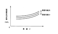
加速要求に応じて変速モードを切り換える変速モード切換手段102は、例えば図5のフローチャートに従って信号処理を行なうことにより加速要求か否かを判断し、変速モードを切り換える。図5は、所定のサイクルタイムで繰り返し実行されるもので、ステップS1では路面勾配Φを読み込み、ステップS2では、アクセル操作量PAPに基づいて加速要求か否かを判断するための加速要求判定値PAPLのマップを路面勾配Φに応じて選択する。すなわち、路面勾配Φが大きい登坂路では、運転者が加速を欲していない場合でも、車両が登坂できる所望の駆動力が得られるようにアクセルペダル83が大きく踏込み操作されることがあるが、そのような場合まで加速変速モードで変速制御が行なわれると、前記図13に示すように却って登坂性能が損なわれる可能性があるため、路面勾配Φが大きい程加速変速モードへの切換が抑制されるようにするのであり、例えば図6に示すように、路面勾配Φが大きい程加速要求判定値マップは増大させられる。また、車速Vが高くなると、加速を欲していない場合でもアクセル操作量PAPは大きくなるため、この加速要求判定値マップは、車速Vをパメラータとして車速Vが大きくなる程加速要求判定値PAPLが大きくなるように設定されている。本実施例では、路面勾配Φが走行抵抗を表している。
The shift mode switching means 102 that switches the shift mode in response to the acceleration request determines, for example, whether or not the acceleration is requested by performing signal processing according to the flowchart of FIG. 5, and switches the shift mode. FIG. 5 is repeatedly executed at a predetermined cycle time. In step S1, the road surface gradient Φ is read. In step S2, an acceleration request determination value for determining whether or not the acceleration request is made based on the accelerator operation amount PAP. The PAPL map is selected according to the road surface gradient Φ. That is, on an uphill road with a large road surface gradient Φ, even if the driver does not want acceleration, the
図5に戻って、ステップS3では、ステップS2で選択した加速要求判定値マップから実際の車速Vに応じて加速要求判定値PAPLを求め、ステップS4では、その加速要求判定値PAPLと実際のアクセル操作量PAPとを比較する。そして、PAP<PAPLであれば運転者が加速を欲していないと判断して、ステップS5で通常変速モードを選択し、前記通常変速手段104に変速制御を実行させる一方、PAP≧PAPLの場合は運転者が加速を欲していると判断して、ステップS6で加速変速モードを選択し、前記リニアシフト手段106に変速制御を実行させる。図9は、路面勾配Φが大きい登坂路での走行時に、上記ステップS4の判断がYES、すなわちPAP≧PAPLとなり、時間t1 で通常変速モードから加速変速モードへ移行した場合のタイムチャートの一例である。 Returning to FIG. 5, in step S3, an acceleration request determination value PAPL is obtained from the acceleration request determination value map selected in step S2 in accordance with the actual vehicle speed V. In step S4, the acceleration request determination value PAPL and the actual accelerator are determined. The manipulated variable PAP is compared. If PAP <PAPL, it is determined that the driver does not want acceleration, and the normal transmission mode is selected in step S5, and the normal transmission means 104 is caused to execute the shift control. On the other hand, if PAP ≧ PAPL, When it is determined that the driver wants acceleration, an acceleration shift mode is selected in step S6, and the linear shift means 106 is caused to execute shift control. FIG. 9 shows an example of a time chart when the judgment in step S4 is YES, that is, PAP ≧ PAPL when the vehicle travels on an uphill road with a large road surface gradient Φ, and the mode shifts from the normal transmission mode to the acceleration transmission mode at time t 1. It is.
リニアシフト手段106によって実行される加速変速モードによる変速制御について、上記図9を参照しつつ具体的に説明すると、先ず、次式(1) に示すように加速時目標回転速度基準値NINTLBとアクセル踏込み補正値NINTLPAPと車速変化補正値NINTLSPDとを加算して目標回転速度NINTを算出する。加速時目標回転速度基準値NINTLBは、図7に示すように路面勾配Φおよび車速Vをパラメータとしてマップや演算式で設定されており、車速Vが小さく路面勾配Φが大きい程大きな変速比γになるように、言い換えれば目標回転速度NINTが高くなるように定められている。この加速時目標回転速度基準値NINTLBは、一連の加速変速モードでの変速制御の継続中は、加速変速モードへ移行した時に最初に求めた一定値がそのまま用いられる。本実施例では、路面勾配Φが大きい程加速時目標回転速度基準値NINTLBが大きくなるため、登坂路では図9に示すように、従来すなわち平坦路における加速時目標回転速度基準値NINTLBよりも大きな値になり、加速変速モードへの移行時の目標回転速度NINTの初期値NINTL0の上昇幅がそれだけ大きくなる。
NINT=NINTLB+NINTLPAP+NINTLSPD ・・・(1)
The shift control in the acceleration shift mode executed by the linear shift means 106 will be described in detail with reference to FIG. 9. First, as shown in the following equation (1), the acceleration target rotational speed reference value NINTLB and accelerator The target rotational speed NINT is calculated by adding the depression correction value NINTLPAP and the vehicle speed change correction value NINTLSPD. As shown in FIG. 7, the target rotational speed reference value NINTLB during acceleration is set by a map or an arithmetic expression using the road surface gradient Φ and the vehicle speed V as parameters, and the speed ratio γ increases as the vehicle speed V decreases and the road surface gradient Φ increases. In other words, the target rotational speed NINT is determined to be high. As the acceleration target rotational speed reference value NINTLB, the constant value obtained first when the shift to the acceleration shift mode is continued is used as it is during the shift control in the series of acceleration shift modes. In this embodiment, the acceleration target rotational speed reference value NINTLB increases as the road surface gradient Φ increases. Therefore, on the uphill road, as shown in FIG. 9, it is larger than the acceleration target rotational speed reference value NINTLB on a conventional road, that is, on a flat road. The initial value NINTTL0 of the target rotational speed NINT at the time of shifting to the acceleration shift mode is increased accordingly.
NINT = NINTLB + NINTLPAP + NINTLSPD (1)
上記アクセル踏込み補正値NINTLPAPは、アクセル操作量PAPすなわち加速要求値が大きい程目標回転速度NINTを高くするための補正値で、例えば図8に示すようにアクセル操作量PAPをパラメータとして予め定められたマップや演算式に従って求められる。また、車速変化補正値NINTLSPDは、車速Vの上昇に対して目標回転速度NINTすなわち入力軸回転速度NINを比例的に増加させるための補正値で、例えば次式(2) に示すように、車速Vの変化速度ΔV或いはサイクルタイム当りの車速Vの変化量ΔVに、所定の補正係数αを掛け算した値を前回の補正値NINTLSPDi-1 に加算することによって求められる。これにより、例えば車速Vが一定の変化率で直線的に増加する場合には、車速変化補正値NINTLSPDも一定の変化率で直線的に増加させられるようになる。これ等のアクセル踏込み補正値NINTLPAP、および車速変化補正値NINTLSPDは、一連の加速変速モードでの変速制御の過程で、所定のサイクルタイムで目標回転速度NINTが算出される度に逐次更新され、車速変化補正値NINTLSPDは車速Vの増加に応じて連続的に増大させられる。上記図8のアクセル踏込み補正値NINTLPAPに関するマップや前記図7の加速時目標回転速度基準値NINTLBに関するマップは、前記図4の変速マップと同様に電子制御装置80のマップ記憶装置94に予め記憶されている。
NINTLSPDi =NINTLSPDi-1 +α×ΔV ・・・(2)
The accelerator depression correction value NINTLPAP is a correction value for increasing the target rotational speed NINT as the accelerator operation amount PAP, that is, the acceleration request value is larger. For example, as shown in FIG. 8, the accelerator operation amount PAP is predetermined as a parameter. It is obtained according to the map and arithmetic expression. The vehicle speed change correction value NINTLSPD is a correction value for increasing the target rotational speed NINT, that is, the input shaft rotational speed NIN in proportion to the increase in the vehicle speed V. For example, as shown in the following equation (2), the vehicle speed It is obtained by adding a value obtained by multiplying the change rate ΔV of V or the change amount ΔV of the vehicle speed V per cycle time by a predetermined correction coefficient α to the previous correction value NINTLSPD i−1 . Thereby, for example, when the vehicle speed V increases linearly at a constant change rate, the vehicle speed change correction value NINTLSPD is also increased linearly at a constant change rate. The accelerator depression correction value NINTLPAP and the vehicle speed change correction value NINTLSPD are sequentially updated every time the target rotational speed NINT is calculated at a predetermined cycle time during the shift control process in a series of acceleration shift modes. The change correction value NINTLSPD is continuously increased as the vehicle speed V increases. The map relating to the accelerator depression correction value NINTLPAP in FIG. 8 and the map relating to the acceleration target rotational speed reference value NINTLB in FIG. 7 are stored in advance in the
NINTLSPD i = NINTLSPD i-1 + α × ΔV (2)
そして、このように前記(1) 式に従って目標回転速度NINTを求めたら、前記通常変速モードと同様に、実際の入力軸回転速度NINが目標回転速度NINTと一致するように、それ等の偏差等に応じて変速制御回路50のデューティソレノイドバルブのデューティ比、或いはリニアソレノイドバルブの駆動電流等をフィードバック制御することにより、プライマリシーブ38の油圧シリンダ38sに対する作動油の供給、排出を制御する。なお、最終的な目標回転速度NINTは、補正に拘らず無段変速機18の最大変速比γmax を超えないようにガードが掛けられる。
Then, when the target rotational speed NINT is obtained in accordance with the equation (1) in this way, as in the normal shift mode, the deviation or the like thereof is set so that the actual input shaft rotational speed NIN matches the target rotational speed NINT. In response to this, feedback control of the duty ratio of the duty solenoid valve of the
このように、本実施例の変速制御装置においては、車両の走行抵抗すなわち路面勾配Φが大きい場合には小さい場合に比較して加速変速モードへ切り換わり難くなるように、その路面勾配Φに応じて加速要求判定値PAPLが設定されるため、アクセル操作量PAPが大きくなる登坂路で運転者の意に反して加速変速モードへ運転モードが切り換えられることが抑制される。これにより、路面勾配Φが小さい平坦路では、運転者の加速要求に応じて加速変速モードへ切り換えられることにより優れた加速フィーリングや乗り心地が得られる一方、路面勾配Φが大きい登坂路で、運転者の意に反して加速変速モードへ切り換えられて十分な駆動力が得られなくなり、登坂性能が損なわれることが防止される。 As described above, in the speed change control device according to the present embodiment, when the running resistance of the vehicle, that is, the road surface gradient Φ, is large, it is difficult to switch to the acceleration gear shift mode as compared with the case where the vehicle running resistance is small. Thus, since the acceleration request determination value PAPL is set, switching the operation mode to the acceleration shift mode against the driver's will on the uphill road where the accelerator operation amount PAP is large is suppressed. As a result, on a flat road with a small road surface gradient Φ, it is possible to obtain excellent acceleration feeling and riding comfort by switching to the acceleration shift mode according to the driver's acceleration request, while on an uphill road with a large road surface gradient Φ, Switching to the acceleration shift mode against the will of the driver prevents a sufficient driving force from being obtained and prevents the climbing performance from being impaired.
また、加速変速モードでは、車速Vの上昇に対して目標回転速度NINTすなわち入力軸回転速度NINが比例的に増加するように、車速変化補正値NINTLSPDによって目標回転速度NINTが補正されるため、路面勾配Φが小さい平坦路で加速変速モードへ切り換えられることにより優れた加速フィーリング等が得られる一方、車速Vの上昇が遅くなったり逆に低下したりするような路面勾配Φが大きい登坂路で、運転者の意に反して加速変速モードへ切り換えられることにより、車速Vの上昇遅れに起因して入力軸回転速度NINの上昇が遅くなって走行性能が損なわれることが効果的に防止される。 In the acceleration shift mode, the target rotational speed NINT is corrected by the vehicle speed change correction value NINTLSPD so that the target rotational speed NINT, that is, the input shaft rotational speed NIN is proportionally increased with the increase in the vehicle speed V. By switching to the acceleration shift mode on a flat road with a small gradient Φ, an excellent acceleration feeling and the like can be obtained, while on an uphill road with a large road gradient Φ where the increase in the vehicle speed V slows or decreases By switching to the acceleration shift mode against the driver's will, the increase in the input shaft rotational speed NIN due to the delay in the increase in the vehicle speed V is effectively prevented from being impaired. .
また、本実施例の加速変速モードでは、路面勾配Φが大きい場合には小さい場合に比較して加速時目標回転速度基準値NINTLBが大きくされ、加速変速モードへ移行した時の目標回転速度の初期値NINTL0の上昇幅が大きくなるため、登坂路で加速変速モードへ切り換えられた場合でもその目標回転速度初期値NINTL0が高くなり、それに応じてエンジン回転速度NEも高くなるため、加速変速モードへの切換に拘らず速やかに大きな駆動力が得られるようになり、優れた登坂性能が得られるようになる。すなわち、平坦路での加速時目標回転速度基準値NINTLBは、車速Vの増加に伴ってエンジン回転速度NEを上昇させながらエンジントルクを増大させることにより、優れた加速フィーリングが得られるように、エンジントルクがピークになる回転速度よりも低回転となるように定められるが、登坂路では、いきなり大きなエンジントルクが得られるように、そのトルク特性に応じて加速時目標回転速度基準値NINTLBが高めに設定されるのである。 In the acceleration shift mode of this embodiment, when the road surface gradient Φ is large, the acceleration target rotational speed reference value NINTLB is made larger than when the road surface gradient Φ is small, and the initial target rotational speed at the time of shifting to the acceleration shift mode is set. Since the increase range of the value NINTL0 becomes large, the target rotation speed initial value NINTL0 is increased even when the acceleration shift mode is switched on the uphill road, and the engine rotation speed NE is accordingly increased. Regardless of the switching, a large driving force can be obtained quickly, and excellent climbing performance can be obtained. That is, the target rotational speed reference value NINTLB during acceleration on a flat road is such that an excellent acceleration feeling can be obtained by increasing the engine torque while increasing the engine rotational speed NE as the vehicle speed V increases. The engine torque is determined to be lower than the peak rotation speed. On the uphill road, the acceleration target rotation speed reference value NINTLB is increased according to the torque characteristics so that suddenly large engine torque can be obtained. It is set to.
なお、上記実施例では、路面勾配Φが大きい程目標回転速度NINTが大きくなるように、加速時目標回転速度基準値NINTLBが路面勾配Φおよび車速Vをパラメータとして設定されていたが、その加速時目標回転速度基準値NINTLBを平坦路において所定の加速性能が得られるように車速Vのみをパラメータとして設定する一方、次式(3) に示すように、前記アクセル踏込み補正値NINTLPAPおよび車速変化補正値NINTLSPDの他に勾配補正値NINTLSLPを加算して目標回転速度NINTを算出するようにしても良い。この場合の勾配補正値NINTLSLPは、例えば図10に示すように路面勾配Φが正で且つ所定値以上の場合に、その路面勾配Φが大きくなる程大きな補正値が設定されるように、路面勾配Φをパメラータとしてマップや演算式等により定められる。この勾配補正値NINTLSLPは、アクセル踏込み補正値NINTLPAPや車速変化補正値NINTLSPDと同様に、所定のサイクルタイムで目標回転速度NINTが算出される度に逐次更新される。上記図10の勾配補正値NINTLSLPに関するマップは、前記アクセル踏込み補正値NINTLPAP等のマップと同様に電子制御装置80のマップ記憶装置94に予め記憶されている。
NINT=NINTLB+NINTLPAP+NINTLSPD
+NINTLSLP ・・・(3)
In the above embodiment, the target rotational speed reference value NINTLB during acceleration is set using the road gradient Φ and the vehicle speed V as parameters so that the target rotational speed NINT increases as the road gradient Φ increases. The target rotational speed reference value NINTLB is set using only the vehicle speed V as a parameter so that a predetermined acceleration performance can be obtained on a flat road. On the other hand, as shown in the following equation (3), the accelerator depression correction value NINTLPAP and the vehicle speed change correction value are set. The target rotational speed NINT may be calculated by adding a gradient correction value NINTLSLP in addition to NINTLSPD. The gradient correction value NINTLSLP in this case is, for example, as shown in FIG. 10, when the road surface gradient Φ is positive and greater than or equal to a predetermined value, the road surface gradient is set such that a larger correction value is set as the road surface gradient Φ increases. Φ is defined by a map, an arithmetic expression, or the like using Pamella. The gradient correction value NINTLSLP is sequentially updated every time the target rotational speed NINT is calculated at a predetermined cycle time, similar to the accelerator depression correction value NINTLPAP and the vehicle speed change correction value NINTLSPD. The map related to the gradient correction value NINTLSLP in FIG. 10 is stored in advance in the
NINT = NINTLB + NINTLPAP + NINTLSPD
+ NINTLSLP (3)
本実施例においても、路面勾配Φが大きい程勾配補正値NINTLSLPが大きくなるため、加速時目標回転速度基準値NINTLBが従来と同じすなわち平坦路の場合と同じであっても、登坂路では図11に示すように加速変速モードの開始当初からその勾配補正値NINTLSLP分だけ目標回転速度NINTが高くなり、それに伴ってエンジン回転速度NEも高くされるため、前記実施例と同様に加速変速モードへの切換に拘らず大きな駆動力により優れた登坂性能が得られる。 Also in this embodiment, since the gradient correction value NINTLSLP increases as the road surface gradient Φ increases, the acceleration target rotational speed reference value NINTLB is the same as that in the conventional case, that is, the same as in the case of a flat road. As shown in FIG. 4, since the target rotational speed NINT is increased by the gradient correction value NINTLSLP from the beginning of the acceleration transmission mode and the engine rotational speed NE is increased accordingly, the switching to the acceleration transmission mode is performed as in the above embodiment. Regardless of this, excellent driving performance can be obtained with a large driving force.
また、前記車速変化補正値NINTLSPDの補正係数αが、図12に示すように路面勾配Φが正で且つ所定値以上の場合に、その路面勾配Φが大きくなる程大きな値となるように、路面勾配Φをパメラータとしてマップや演算式等により設定されるようにしても良い。その場合も、路面勾配Φが大きい程補正係数αが大きくなり、それに伴って車速変化補正値NINTLSPDが大きくされて、目標回転速度NINTが高くなるため、前記実施例と同様の作用効果が得られる。この補正係数αは、アクセル踏込み補正値NINTLPAPと同様に、所定のサイクルタイムで目標回転速度NINTが算出される度に逐次更新される。また、上記図12の補正係数αに関するマップは、アクセル踏込み補正値NINTLPAP等のマップと同様に電子制御装置80のマップ記憶装置94に予め記憶される。
Further, when the road surface gradient Φ is positive and greater than or equal to a predetermined value as shown in FIG. 12, the vehicle surface speed change correction value NINTLSPD has a larger value as the road surface gradient Φ increases. The gradient Φ may be set as a parameter by a map, an arithmetic expression, or the like. Also in this case, the correction coefficient α increases as the road surface gradient Φ increases, and accordingly, the vehicle speed change correction value NINTLSPD increases, and the target rotational speed NINT increases. Therefore, the same effect as in the above embodiment can be obtained. . This correction coefficient α is sequentially updated every time the target rotational speed NINT is calculated in a predetermined cycle time, similarly to the accelerator depression correction value NINTLPAP. The map relating to the correction coefficient α in FIG. 12 is stored in advance in the
以上、本発明の実施例を図面に基づいて詳細に説明したが、これ等はあくまでも一実施形態であり、本発明は当業者の知識に基づいて種々の変更、改良を加えた態様で実施することができる。 As mentioned above, although the Example of this invention was described in detail based on drawing, these are one Embodiment to the last, This invention is implemented in the aspect which added the various change and improvement based on the knowledge of those skilled in the art. be able to.
18:ベルト式無段変速機(無段変速機) 36:入力軸 50:変速制御回路 80:電子制御装置 88:車速センサ 90:入力軸回転速度センサ 92:勾配センサ 102:変速モード切換手段 104:通常変速手段(通常変速モード) 106:リニアシフト手段(加速変速モード) Φ:路面勾配(走行抵抗) PAP:アクセル操作量(加速要求値) PAPL:加速要求判定値 NINTLB:加速時目標回転速度基準値 NINTL0:加速時目標回転速度初期値(上昇幅) NINTLSLP:勾配補正値 18: Belt type continuously variable transmission (continuously variable transmission) 36: Input shaft 50: Shift control circuit 80: Electronic control device 88: Vehicle speed sensor 90: Input shaft rotational speed sensor 92: Gradient sensor 102: Shift mode switching means 104 : Normal shift means (normal shift mode) 106: Linear shift means (acceleration shift mode) Φ: Road gradient (travel resistance) PAP: Accelerator operation amount (acceleration request value) PAPL: Acceleration request determination value NINTLB: Target rotation speed during acceleration Reference value NINTTL0: Initial value of target rotational speed during acceleration (increase) NINTLSLP: Slope correction value
Claims (5)
車両の走行抵抗が大きい場合には小さい場合に比較して前記加速変速モードへ切り換わり難くなるように、該走行抵抗に応じて前記加速要求判定値が定められている
ことを特徴とする車両用無段変速機の変速制御装置。 Shift mode switching means for determining whether or not the driver's acceleration request value is equal to or greater than a predetermined acceleration request determination value and switching the shift mode from the normal shift mode to the acceleration shift mode when the driver's acceleration request value is equal to or greater than the acceleration request determination value; In a transmission control device for a continuously variable transmission for a vehicle,
The acceleration request determination value is determined according to the running resistance so that it is difficult to switch to the acceleration shift mode when the running resistance of the vehicle is large compared to when the running resistance is small. A transmission control device for a continuously variable transmission.
前記走行抵抗は路面勾配で、前記加速要求判定値は該路面勾配が大きい場合には小さい場合に比較して大きくされる
ことを特徴とする請求項1に記載の車両用無段変速機の変速制御装置。 The acceleration request value is an accelerator operation amount, and the shift mode switching means determines whether the accelerator operation amount is equal to or greater than the acceleration request determination value and switches the shift mode.
The shift of the continuously variable transmission for a vehicle according to claim 1, wherein the running resistance is a road surface gradient, and the acceleration request determination value is increased when the road surface gradient is large compared to a small case. Control device.
ことを特徴とする請求項1または2に記載の車両用無段変速機の変速制御装置。 The shift of the continuously variable transmission for a vehicle according to claim 1 or 2, wherein in the acceleration shift mode, shift control is performed such that the input shaft rotation speed increases in proportion to an increase in vehicle speed. Control device.
ことを特徴とする請求項1〜3の何れか1項に記載の車両用無段変速機の変速制御装置。 The shift control is performed in the acceleration shift mode so that the input shaft rotation speed is higher when the running resistance is large than when the running resistance is small. A shift control device for a continuously variable transmission for a vehicle according to claim.
ことを特徴とする請求項1〜4の何れか1項に記載の車両用無段変速機の変速制御装置。 The increase in the input shaft rotation speed when shifting from the normal speed change mode to the acceleration speed change mode is larger when the running resistance is large than when the running resistance is small. 2. A transmission control apparatus for a continuously variable transmission for a vehicle according to item 1.
Priority Applications (5)
| Application Number | Priority Date | Filing Date | Title |
|---|---|---|---|
| JP2007175590A JP4941133B2 (en) | 2007-07-03 | 2007-07-03 | Shift control device for continuously variable transmission for vehicle |
| PCT/JP2008/061441 WO2009004946A1 (en) | 2007-07-03 | 2008-06-24 | Shift control device for vehicular stepless transmission |
| AT08790580T ATE554318T1 (en) | 2007-07-03 | 2008-06-24 | SHIFT CONTROL DEVICE FOR A VEHICLE CONTINUOUSLY VARIABLE TRANSMISSION |
| US12/667,466 US8527166B2 (en) | 2007-07-03 | 2008-06-24 | Shift control device for vehicular continuously variable transmission |
| EP08790580A EP2175172B1 (en) | 2007-07-03 | 2008-06-24 | Shift control device for vehicular stepless transmission |
Applications Claiming Priority (1)
| Application Number | Priority Date | Filing Date | Title |
|---|---|---|---|
| JP2007175590A JP4941133B2 (en) | 2007-07-03 | 2007-07-03 | Shift control device for continuously variable transmission for vehicle |
Publications (2)
| Publication Number | Publication Date |
|---|---|
| JP2009014085A true JP2009014085A (en) | 2009-01-22 |
| JP4941133B2 JP4941133B2 (en) | 2012-05-30 |
Family
ID=40225994
Family Applications (1)
| Application Number | Title | Priority Date | Filing Date |
|---|---|---|---|
| JP2007175590A Expired - Fee Related JP4941133B2 (en) | 2007-07-03 | 2007-07-03 | Shift control device for continuously variable transmission for vehicle |
Country Status (5)
| Country | Link |
|---|---|
| US (1) | US8527166B2 (en) |
| EP (1) | EP2175172B1 (en) |
| JP (1) | JP4941133B2 (en) |
| AT (1) | ATE554318T1 (en) |
| WO (1) | WO2009004946A1 (en) |
Cited By (3)
| Publication number | Priority date | Publication date | Assignee | Title |
|---|---|---|---|---|
| JP2013133836A (en) * | 2011-12-26 | 2013-07-08 | Jatco Ltd | Shift control device for continuously variable transmission |
| JP2013133866A (en) * | 2011-12-26 | 2013-07-08 | Jatco Ltd | Shift control device for continuously variable transmission |
| JP2014213701A (en) * | 2013-04-25 | 2014-11-17 | トヨタ自動車株式会社 | Vehicle |
Families Citing this family (10)
| Publication number | Priority date | Publication date | Assignee | Title |
|---|---|---|---|---|
| WO2011075591A1 (en) | 2009-12-17 | 2011-06-23 | Merial Limited | Anti parasitic dihydroazole compounds and compositions comprising same |
| JP5303003B2 (en) | 2011-06-07 | 2013-10-02 | ジヤトコ株式会社 | Automatic transmission |
| JP5626471B2 (en) * | 2011-07-28 | 2014-11-19 | 日産自動車株式会社 | Speed change control device and speed change control method for continuously variable transmission |
| US8935065B2 (en) * | 2011-11-16 | 2015-01-13 | Aisin Aw Co., Ltd. | Control device and control method for automatic transmission |
| CN104334931B (en) | 2012-06-07 | 2016-05-04 | 本田技研工业株式会社 | The speed-change control device of automatic transmission |
| GB201215963D0 (en) * | 2012-09-06 | 2012-10-24 | Jaguar Cars | Vehicle control system and method |
| PT3063144T (en) | 2013-11-01 | 2021-10-28 | Boehringer Ingelheim Animal Health Usa Inc | Antiparisitic and pesticidal isoxazoline compounds |
| CN106062433B (en) * | 2014-03-10 | 2018-01-16 | 爱信艾达株式会社 | The control device and control method of buncher |
| US11584461B2 (en) * | 2017-01-09 | 2023-02-21 | Allison Transmission, Inc. | System and method for reporting on vehicle characteristics determined by transmission control circuit |
| CN114127446A (en) * | 2019-07-01 | 2022-03-01 | 蒂姆工业公司 | Uniform clamp actuated infinitely variable transmission system |
Citations (5)
| Publication number | Priority date | Publication date | Assignee | Title |
|---|---|---|---|---|
| JPH01195145A (en) * | 1988-01-29 | 1989-08-07 | Mazda Motor Corp | Control device for continuously variable transmission |
| JPH11257481A (en) * | 1998-03-13 | 1999-09-21 | Nissan Motor Co Ltd | Shift controller for continuously variable transmission |
| JP2003172446A (en) * | 2001-12-05 | 2003-06-20 | Fuji Heavy Ind Ltd | Variable speed control device for transmission |
| JP2004125072A (en) * | 2002-10-03 | 2004-04-22 | Fuji Heavy Ind Ltd | Shift controller for continuously variable transmission |
| JP2004162799A (en) * | 2002-11-13 | 2004-06-10 | Nissan Motor Co Ltd | Speed change controller of continuously-variable transmission |
Family Cites Families (6)
| Publication number | Priority date | Publication date | Assignee | Title |
|---|---|---|---|---|
| JP3409669B2 (en) * | 1997-03-07 | 2003-05-26 | 日産自動車株式会社 | Transmission control device for continuously variable transmission |
| JPH11247987A (en) | 1998-03-06 | 1999-09-14 | Fuji Heavy Ind Ltd | Transmission control device for continuously variable transmission |
| JP4955164B2 (en) | 2001-09-07 | 2012-06-20 | 富士重工業株式会社 | Shift control device for continuously variable transmission |
| JP3812391B2 (en) * | 2001-09-26 | 2006-08-23 | 日産自動車株式会社 | Vehicle driving force control device |
| JP2004100905A (en) | 2002-09-12 | 2004-04-02 | Fuji Heavy Ind Ltd | Control device for continuously variable transmission |
| DE60335697D1 (en) | 2002-11-13 | 2011-02-24 | Nissan Motor | Shift control for a continuously variable transmission |
-
2007
- 2007-07-03 JP JP2007175590A patent/JP4941133B2/en not_active Expired - Fee Related
-
2008
- 2008-06-24 AT AT08790580T patent/ATE554318T1/en active
- 2008-06-24 EP EP08790580A patent/EP2175172B1/en not_active Not-in-force
- 2008-06-24 WO PCT/JP2008/061441 patent/WO2009004946A1/en active Application Filing
- 2008-06-24 US US12/667,466 patent/US8527166B2/en active Active
Patent Citations (5)
| Publication number | Priority date | Publication date | Assignee | Title |
|---|---|---|---|---|
| JPH01195145A (en) * | 1988-01-29 | 1989-08-07 | Mazda Motor Corp | Control device for continuously variable transmission |
| JPH11257481A (en) * | 1998-03-13 | 1999-09-21 | Nissan Motor Co Ltd | Shift controller for continuously variable transmission |
| JP2003172446A (en) * | 2001-12-05 | 2003-06-20 | Fuji Heavy Ind Ltd | Variable speed control device for transmission |
| JP2004125072A (en) * | 2002-10-03 | 2004-04-22 | Fuji Heavy Ind Ltd | Shift controller for continuously variable transmission |
| JP2004162799A (en) * | 2002-11-13 | 2004-06-10 | Nissan Motor Co Ltd | Speed change controller of continuously-variable transmission |
Cited By (3)
| Publication number | Priority date | Publication date | Assignee | Title |
|---|---|---|---|---|
| JP2013133836A (en) * | 2011-12-26 | 2013-07-08 | Jatco Ltd | Shift control device for continuously variable transmission |
| JP2013133866A (en) * | 2011-12-26 | 2013-07-08 | Jatco Ltd | Shift control device for continuously variable transmission |
| JP2014213701A (en) * | 2013-04-25 | 2014-11-17 | トヨタ自動車株式会社 | Vehicle |
Also Published As
| Publication number | Publication date |
|---|---|
| ATE554318T1 (en) | 2012-05-15 |
| US8527166B2 (en) | 2013-09-03 |
| EP2175172A4 (en) | 2010-09-29 |
| JP4941133B2 (en) | 2012-05-30 |
| EP2175172A1 (en) | 2010-04-14 |
| EP2175172B1 (en) | 2012-04-18 |
| WO2009004946A1 (en) | 2009-01-08 |
| US20100191428A1 (en) | 2010-07-29 |
Similar Documents
| Publication | Publication Date | Title |
|---|---|---|
| JP4941133B2 (en) | Shift control device for continuously variable transmission for vehicle | |
| US9002601B2 (en) | Shift control apparatus of continuously variable transmission | |
| WO2009128304A1 (en) | Device and method for controlling continuously variable transmission | |
| JP5786843B2 (en) | Shift control device for continuously variable transmission | |
| US8948988B2 (en) | Speed ratio control device of continuously variable transmission for vehicle | |
| JP5803770B2 (en) | Control device for continuously variable transmission for vehicle | |
| JP2004125072A (en) | Shift controller for continuously variable transmission | |
| JP4325080B2 (en) | Vehicle control apparatus equipped with continuously variable transmission | |
| JP2010196881A (en) | Control device for vehicle | |
| JP2014137105A (en) | Shift control device of continuously variable transmission for vehicle | |
| JP5370293B2 (en) | Control device for continuously variable transmission for vehicle | |
| JP2009047269A (en) | Speed change controller for continuously variable transmission of vehicle | |
| JP2010261518A (en) | Control device for vehicle provided with belt-type continuously variable transmission | |
| JP2009092176A (en) | Shift controller of vehicular continuously variable transmission | |
| JP2004286106A (en) | Shift control device for vehicular continuously variable transmission | |
| JP5500243B2 (en) | Vehicle, transmission control method and control apparatus | |
| JP6065578B2 (en) | Control device and control method for continuously variable transmission | |
| JP5691733B2 (en) | Lockup control device for continuously variable transmission for vehicle | |
| JP2012172761A (en) | Control device of lock-up clutch for vehicle | |
| JP5333667B2 (en) | Control device and control method for vehicle, continuously variable transmission | |
| JP2009014105A (en) | Control device of vehicular continuously variable transmission | |
| JP2011247305A (en) | Automatic transmission control device for vehicle | |
| JP5186938B2 (en) | Control device for continuously variable transmission | |
| JP4586506B2 (en) | Control device for continuously variable transmission | |
| JP2004116641A (en) | Speed change controller of continuously-variable transmission |
Legal Events
| Date | Code | Title | Description |
|---|---|---|---|
| A131 | Notification of reasons for refusal |
Free format text: JAPANESE INTERMEDIATE CODE: A131 Effective date: 20110712 |
|
| A521 | Request for written amendment filed |
Free format text: JAPANESE INTERMEDIATE CODE: A523 Effective date: 20110822 |
|
| TRDD | Decision of grant or rejection written | ||
| A01 | Written decision to grant a patent or to grant a registration (utility model) |
Free format text: JAPANESE INTERMEDIATE CODE: A01 Effective date: 20120131 |
|
| A01 | Written decision to grant a patent or to grant a registration (utility model) |
Free format text: JAPANESE INTERMEDIATE CODE: A01 |
|
| A61 | First payment of annual fees (during grant procedure) |
Free format text: JAPANESE INTERMEDIATE CODE: A61 Effective date: 20120213 |
|
| R151 | Written notification of patent or utility model registration |
Ref document number: 4941133 Country of ref document: JP Free format text: JAPANESE INTERMEDIATE CODE: R151 |
|
| FPAY | Renewal fee payment (event date is renewal date of database) |
Free format text: PAYMENT UNTIL: 20150309 Year of fee payment: 3 |
|
| LAPS | Cancellation because of no payment of annual fees |