JP2009012736A - Auxiliary sun visor for automobile - Google Patents
Auxiliary sun visor for automobile Download PDFInfo
- Publication number
- JP2009012736A JP2009012736A JP2007196703A JP2007196703A JP2009012736A JP 2009012736 A JP2009012736 A JP 2009012736A JP 2007196703 A JP2007196703 A JP 2007196703A JP 2007196703 A JP2007196703 A JP 2007196703A JP 2009012736 A JP2009012736 A JP 2009012736A
- Authority
- JP
- Japan
- Prior art keywords
- sun visor
- shielding plate
- light shielding
- hinge
- light
- Prior art date
- Legal status (The legal status is an assumption and is not a legal conclusion. Google has not performed a legal analysis and makes no representation as to the accuracy of the status listed.)
- Pending
Links
Images


Landscapes
- Pivots And Pivotal Connections (AREA)
Abstract
Description
本発明はサンバイザの遮光範囲を拡大するとともに、透過率を調整、選択可能にした自動車用補助サンバイザに関する。 The present invention relates to an auxiliary sun visor for automobiles in which the light shielding range of the sun visor is expanded and the transmittance can be adjusted and selected.
一般に自動車用サンバイザとしては、不透明な材料で矩形状に形成され、その役目としては運転者の日避け具として用いられる。また、上記既存のサンバイザに遮光範囲を拡大するための補助サンバイザを取り付けることが知られている。 In general, a sun visor for an automobile is formed in a rectangular shape with an opaque material, and is used as a driver's sun protection device for its role. It is also known to attach an auxiliary sun visor for expanding the light shielding range to the existing sun visor.
この種の自動車用補助サンバイザに関する技術が特許文献1に開示されている。
特許文献1に開示されるサンバイザは既存のサンバイザの下方に取り付け、使用時に下方に回転して遮光面積を拡大するもので、矩形状に合成樹脂で形成した半透明或いはハ−フミラ−の遮光板と、弾性力を有する略U字体に形成させると共に略U字体の下方に開口用のツマミ片を突設する挾持部材とから構成し、更に遮光板の動きを制動させて任意角度の設定を可能とするために、ヒンジ部材にスプリングピンを用いる。また挾持部材に固着するガイドレ−ルと、該ガイドレ−ルに挿入する左右移動可能なスライドブロックとから成るスライド部材を具備させ、遮光面積を広げることができる。 The sun visor disclosed in
既存のサンバイザや上記の補助サンバイザを用いた場合、運転者が選択できる遮光の変化量はサンバイザの占有面積による。しかし、運転者が運転に意識を集中するなかで刻々と変化する光線の量や方向の変化に瞬時に対応するには、経験上サンバイザを手で回転、移動させるより顔や視線の方向を変えて幻惑を回避することが多く、前方不注意の要因となり易く遮光面積、透過率の調整、選択の観点からさらなる改良の余地があった。また、近年自動車のヘッドランプの照度が上がっていることから、朝夕のみならず夜間走行時に対向車のヘッドランプの光線で幻惑する場合が多いという課題があった。 When an existing sun visor or the above-described auxiliary sun visor is used, the amount of change in shading that can be selected by the driver depends on the area occupied by the sun visor. However, in order to respond instantly to changes in the amount and direction of light rays as the driver concentrates on driving, experience changes the direction of the face and line of sight rather than rotating and moving the sun visor by hand. Therefore, there is room for further improvement in terms of light shielding area, transmittance adjustment, and selection. Moreover, since the illuminance of automobile headlamps has been increasing in recent years, there has been a problem that the headlamps of oncoming vehicles are often dazzled when driving at night as well as morning and evening.
前記、特許文献1の補助サンバイザは既存のサンバイザの下部とその車幅方向でスライドブロックがスライド可能な範囲までは遮光範囲を拡大できるが、夜間の走行時を含めた光線の当たり具合や方向、角度により透過率を調整、選択可能とする課題は示唆していない。また、上記補助サンバイザを回動し任意角度に設定をするために、ヒンジ部材にスプリングピンを用い、挾持部材に固着するガイドレ−ルと、該ガイドレ−ルに挿入する左右移動可能なスライドブロックとから成るスライド部材を具備させる構造となっており、挾持部材と回転軸部を一体に成型するとともに、第2遮光板とヒンジ部を一体に形成することにより構成部品を簡単にする構造は開示されていない。 The auxiliary sun visor of
本発明は上記の課題を解決するため、既存のサンバーザに簡単に着脱でき、朝夕夜間の運転中の眩惑を回避するように遮光面積、透過率を調整、選択でき、しかも簡単な部品構成とした自動車用補助サンバイザを提供するものである。 In order to solve the above-mentioned problems, the present invention can be easily attached to and detached from an existing sunbazar, and the light shielding area and transmittance can be adjusted and selected so as to avoid dazzling during driving in the morning and evening. An auxiliary sun visor for automobiles is provided.
本発明は上記課題を解決するために、自動車室内に既存のサンバイザを具備し、該サンバイザの下方に挾持部材を形成し、一方の挾持部材と他方の挾持部材を連結する回転軸部を形成し、半透明の合成樹脂で矩形状に成型し上端部に上記回転軸部に嵌合するヒンジ部により回動自在に形成された第1遮光板と、半透明の合成樹脂で矩形状に成型し該第1遮光板と相互に重合した部分を形成し左右移動させて遮光面積と透過率を選択、調整可能とした第2遮光板を具備する構造とした。 In order to solve the above-described problems, the present invention includes an existing sun visor in an automobile cabin, a holding member is formed below the sun visor, and a rotating shaft portion that connects one holding member and the other holding member is formed. The first light-shielding plate is formed in a rectangular shape with a semi-transparent synthetic resin and is pivotally formed at the upper end portion by a hinge portion fitted to the rotating shaft portion, and is molded into a rectangular shape with a semi-transparent synthetic resin. A portion overlapping with the first light shielding plate is formed and moved to the left and right to have a structure including a second light shielding plate which can select and adjust the light shielding area and transmittance.
本発明は上記のように構成させたことにより、既存のサンバイザに簡単に着脱でき、光線の当たり具合や方向、角度により第1遮光板と第2遮光板を適宜回転スライドさせることにより、遮光の面積を拡大させたり透過率を瞬時に調整、選択でき、しかも構成部品を簡単にすることで安価に製造できるという優れた効果を奏する。 Since the present invention is configured as described above, it can be easily attached to and detached from an existing sun visor. By appropriately rotating and sliding the first light shielding plate and the second light shielding plate according to the contact state, direction, and angle of light, the light shielding effect can be obtained. It has an excellent effect that the area can be enlarged and the transmittance can be adjusted and selected instantaneously, and the components can be simplified and manufactured at low cost.
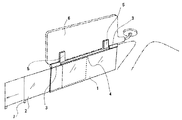
図1,図2は本発明の実施例を示す図であり、この図に基づき説明する。
1は矩形状に合成樹脂で形成した半透明の第1遮光板であり、5は既存のサンバイザ6に挾持するための弾性力を有した略U字体に形成させる合成樹脂製の挾持部材である。FIG. 1 and FIG. 2 are diagrams showing an embodiment of the present invention, which will be described with reference to FIG.
また前記挾持部材5は左右に一対設けられ、回転軸部4で連結されるように合成樹脂などで一体に成型されている。また、回転軸部4の断面は楕円になっており、ヒンジ部3と嵌合し第1遮光板を回転した時任意の角度で停止できるように、楕円の長軸寸法がヒンジ部3の内径より少し長く設定されている。ヒンジ部3は管状に形成され、一方のヒンジ部3は断面がC状になっており回転軸部を嵌入できる構造となっている。 A pair of the
2は第2遮光板であり、半透明の合成樹脂で矩形状に形成し第1遮光板と同程度の透過率を具備し、第1遮光板の裏面に重なった状態で構成され第1遮光板のスライドガイド10に沿って左右に移動可能である。
図3は本発明の実施例の第1遮光板、および第2遮光板の裏面を示す図である。第2遮光板2の裏面上部にはストッパ8を設け下部には引き出し摘み部7を設ける。第1遮光板1の裏面にはその上端と下端にスライドガイド10を設け、第2遮光板2がスライドした時ストッパ8と当接するストッパ受け部11を設ける。また、引き出し摘み部7と当接する切欠部9を設ける。 FIG. 3 is a diagram illustrating the back surfaces of the first light shielding plate and the second light shielding plate according to the embodiment of the present invention. A
本実施例では第2遮光板が第1遮光板の裏面に重なった状態になっているが、第2遮光板が第1遮光板に完全に内蔵されているように構成してもよい。 In the present embodiment, the second light shielding plate is in a state of being overlapped with the back surface of the first light shielding plate. However, the second light shielding plate may be completely built in the first light shielding plate.
本発明の使用方法について説明する。先ず、自動車室内の既存のサンバイザ6に本発明の弾性力を有する略U字体の挾持部材5を既存のサンバイザ6の下端部に差し込む。次に、第1遮光板を回転軸部4を中心に上方へ回転させ、既存のサンバイザ6に重ねる。この状態で本発明に係るサンバイザは既存のサンバーザに重ねて収納される。 A method of using the present invention will be described. First, the substantially U-shaped holding
本発明に係るサンバイザを使用する場合は、まず第1遮光板1を回転軸部4により下方に回転させる。このとき、日光の角度によって第1遮光板1を適切な角度に位置させる。この状態で既存のサンバイザと同様に光線は透過しない。走行中にさらに幻惑がある場合は第2遮光板2を遮光できる位置まで移動する。この時、第1遮光板1と第2遮光板2と重合する部分では完全に遮光され第1遮光板1または第2遮光板2のみの部分では50%程度の透過光となり位置を適宜移動することで遮光面積と透過率を選択、調整する。 When using the sun visor according to the present invention, first, the first
本発明に係るサンバイザを収納する場合は、上記の動作を順次戻ることにより可能である。すなわち、第2遮光板2を回転軸部4に沿って移動し第1遮光板1に重合するように収納する。次に、第1遮光板1を回転軸部4により回転して既存のサンバイザ6の裏面に収納する。 When storing the sun visor according to the present invention, it is possible to return the above operations in sequence. That is, the second
本実施例では、第1遮光板1は全体が均一の半透明な樹脂で形成されるが、例えば第1遮光板1の一部分の透過率を変えるように構成すること、或いは先端部から段階的に透過率を変えて構成してもよい。又、第1遮光板1は半透明な樹脂の他に、ハ−フミラ−を用いてもよい。第2遮光板2についても同様である。さらに第1遮光板1がハーフミラーになっており、第2遮光板を半透明な樹脂で構成してもよい。 In the present embodiment, the entire first
したがって、本発明の補助サンバイザによれば、既存のサンバイザ−6の下部に挾持でき、着脱が極めて容易であり、本発明品が不要な際はいつでも必要に応じて折り畳み取外しができるため邪魔にならない。また、自動車走行中に既存のサンバイザ6では遮光できない範囲を遮光できる。さらに本発明品を任意の位置に移動して遮光の度合いを調整できることから、朝夕夜間を問わず運転者の幻惑や前方不注意の要因を回避でき安全運転に寄与する。 Therefore, according to the auxiliary sun visor of the present invention, it can be held on the lower part of the existing sun visor-6, it is very easy to attach and detach, and when the product of the present invention is not needed, it can be folded and removed as necessary so that it does not get in the way. . Further, it is possible to shield the area that cannot be shielded by the existing sun visor 6 while the vehicle is running. Furthermore, since the product of the present invention can be moved to an arbitrary position and the degree of light shielding can be adjusted, it is possible to avoid the driver's dazzling and forward inattention factors regardless of morning and evening and contribute to safe driving.
1 第1遮光板
2 第2遮光板
3 ヒンジ部材
4 回転軸部
5 挾持部材
6 既存のサンバイザ
7 引き出し摘み部
8 ストッパ
9 切欠部
10 スライドガイド
11 ストッパ受け部DESCRIPTION OF
Claims (3)
Priority Applications (1)
| Application Number | Priority Date | Filing Date | Title |
|---|---|---|---|
| JP2007196703A JP2009012736A (en) | 2007-06-30 | 2007-06-30 | Auxiliary sun visor for automobile |
Applications Claiming Priority (1)
| Application Number | Priority Date | Filing Date | Title |
|---|---|---|---|
| JP2007196703A JP2009012736A (en) | 2007-06-30 | 2007-06-30 | Auxiliary sun visor for automobile |
Publications (1)
| Publication Number | Publication Date |
|---|---|
| JP2009012736A true JP2009012736A (en) | 2009-01-22 |
Family
ID=40354143
Family Applications (1)
| Application Number | Title | Priority Date | Filing Date |
|---|---|---|---|
| JP2007196703A Pending JP2009012736A (en) | 2007-06-30 | 2007-06-30 | Auxiliary sun visor for automobile |
Country Status (1)
| Country | Link |
|---|---|
| JP (1) | JP2009012736A (en) |
Cited By (3)
| Publication number | Priority date | Publication date | Assignee | Title |
|---|---|---|---|---|
| CN103625248A (en) * | 2013-12-05 | 2014-03-12 | 富卓汽车内饰(安徽)有限公司 | Sun-shading plate system for vehicle |
| CN103625247A (en) * | 2013-12-05 | 2014-03-12 | 富卓汽车内饰(安徽)有限公司 | Sun-shading plate for vehicle |
| CN114500866A (en) * | 2022-02-10 | 2022-05-13 | 江苏泽景汽车电子股份有限公司 | Shading method, shading system, electronic equipment and storage medium |
-
2007
- 2007-06-30 JP JP2007196703A patent/JP2009012736A/en active Pending
Cited By (3)
| Publication number | Priority date | Publication date | Assignee | Title |
|---|---|---|---|---|
| CN103625248A (en) * | 2013-12-05 | 2014-03-12 | 富卓汽车内饰(安徽)有限公司 | Sun-shading plate system for vehicle |
| CN103625247A (en) * | 2013-12-05 | 2014-03-12 | 富卓汽车内饰(安徽)有限公司 | Sun-shading plate for vehicle |
| CN114500866A (en) * | 2022-02-10 | 2022-05-13 | 江苏泽景汽车电子股份有限公司 | Shading method, shading system, electronic equipment and storage medium |
Similar Documents
| Publication | Publication Date | Title |
|---|---|---|
| US4982992A (en) | Clip on flat sun visor | |
| US8038199B2 (en) | Visor | |
| US6189947B1 (en) | Sun visor extension device | |
| JPH01237224A (en) | Sunvisor for automobile | |
| US20110109117A1 (en) | Pivoted visor assembly | |
| US7731265B1 (en) | Auxiliary sun visor attachment and associated method | |
| US10232686B2 (en) | Sun visor with slide on rod function | |
| JP2009012736A (en) | Auxiliary sun visor for automobile | |
| US20130033059A1 (en) | Inserted auxiliary sun visor for vehicles | |
| US9669684B2 (en) | Clip on car visor extension | |
| US8714621B2 (en) | Visor with movable pivot | |
| US6679311B2 (en) | Magnetic sun shade system | |
| KR100676677B1 (en) | Mechanism of change of position and posture between two connected objects | |
| KR20090102336A (en) | Mirror device for sun visor of vehicle | |
| GB2173461A (en) | Windscreen visor | |
| KR100974415B1 (en) | Sun protection sun visor | |
| KR20190032915A (en) | sun visor for cars with length adjustable | |
| US20220118827A1 (en) | Apparatus and method to increase sun visor performance | |
| JP3018343U (en) | Auxiliary sun visor for automobiles | |
| KR200353468Y1 (en) | A device to protect beam for a car | |
| US1550252A (en) | Light-shading device | |
| EP2977265B1 (en) | Light assembly for a motor vehicle and motor vehicle | |
| JP3947509B2 (en) | Sun visor | |
| JP2022117235A (en) | Concealed automotive light shield device with slide | |
| TW202229031A (en) | Concealed automobile glare shield device with sliding groove |