JP2009012730A - Engine start-up device for power transmission device for hybrid car - Google Patents

Engine start-up device for power transmission device for hybrid car Download PDF

Info

Publication number
JP2009012730A
JP2009012730A JP2007180211A JP2007180211A JP2009012730A JP 2009012730 A JP2009012730 A JP 2009012730A JP 2007180211 A JP2007180211 A JP 2007180211A JP 2007180211 A JP2007180211 A JP 2007180211A JP 2009012730 A JP2009012730 A JP 2009012730A
Authority
JP
Japan
Prior art keywords
engine
electric motor
differential
speed
shifting
Prior art date
Legal status (The legal status is an assumption and is not a legal conclusion. Google has not performed a legal analysis and makes no representation as to the accuracy of the status listed.)
Pending
Application number
JP2007180211A
Other languages
Japanese (ja)
Inventor
Toru Matsubara
亨 松原
Kenta Kumazaki
健太 熊▲崎▼
Atsushi Tabata
淳 田端
Current Assignee (The listed assignees may be inaccurate. Google has not performed a legal analysis and makes no representation or warranty as to the accuracy of the list.)
Toyota Motor Corp
Original Assignee
Toyota Motor Corp
Priority date (The priority date is an assumption and is not a legal conclusion. Google has not performed a legal analysis and makes no representation as to the accuracy of the date listed.)
Filing date
Publication date
Application filed by Toyota Motor Corp filed Critical Toyota Motor Corp
Priority to JP2007180211A priority Critical patent/JP2009012730A/en
Priority to US12/216,578 priority patent/US8197384B2/en
Priority to EP08252344.0A priority patent/EP2014498B1/en
Priority to CN2008101280042A priority patent/CN101342902B/en
Publication of JP2009012730A publication Critical patent/JP2009012730A/en
Pending legal-status Critical Current

Links

Images

Classifications

    • YGENERAL TAGGING OF NEW TECHNOLOGICAL DEVELOPMENTS; GENERAL TAGGING OF CROSS-SECTIONAL TECHNOLOGIES SPANNING OVER SEVERAL SECTIONS OF THE IPC; TECHNICAL SUBJECTS COVERED BY FORMER USPC CROSS-REFERENCE ART COLLECTIONS [XRACs] AND DIGESTS
    • Y02TECHNOLOGIES OR APPLICATIONS FOR MITIGATION OR ADAPTATION AGAINST CLIMATE CHANGE
    • Y02TCLIMATE CHANGE MITIGATION TECHNOLOGIES RELATED TO TRANSPORTATION
    • Y02T10/00Road transport of goods or passengers
    • Y02T10/60Other road transportation technologies with climate change mitigation effect
    • Y02T10/62Hybrid vehicles
    • YGENERAL TAGGING OF NEW TECHNOLOGICAL DEVELOPMENTS; GENERAL TAGGING OF CROSS-SECTIONAL TECHNOLOGIES SPANNING OVER SEVERAL SECTIONS OF THE IPC; TECHNICAL SUBJECTS COVERED BY FORMER USPC CROSS-REFERENCE ART COLLECTIONS [XRACs] AND DIGESTS
    • Y02TECHNOLOGIES OR APPLICATIONS FOR MITIGATION OR ADAPTATION AGAINST CLIMATE CHANGE
    • Y02TCLIMATE CHANGE MITIGATION TECHNOLOGIES RELATED TO TRANSPORTATION
    • Y02T10/00Road transport of goods or passengers
    • Y02T10/60Other road transportation technologies with climate change mitigation effect
    • Y02T10/7072Electromobility specific charging systems or methods for batteries, ultracapacitors, supercapacitors or double-layer capacitors

Abstract

<P>PROBLEM TO BE SOLVED: To provide a controller for improving responsiveness of driving torque in response to the request of a driver when a traveling state by a motor is switched to a traveling state by an engine in a power transmission device for a hybrid car equipped with an engine and a motor as a power source for the traveling of the vehicle. <P>SOLUTION: Since an engine start-up means 94 starts up an engine 8 by changing the start-up system of the engine 8 under shifting of an automatic transmission portion 20, though in the conventional engine starting method, the engine is started up during non-shifting of the automatic transmission portion 20, an adverse influence due to an operation to start-up the engine 8 on the shifting operation of the automatic transmission portion 20 can be reduced. Since the operation to start-up the engine 8 begins to be executed during the shifting of the automatic transmission portion 20, it is possible to improve responsiveness to acceleration request by the driver as compared with a case that the operation is started after the automatic transmission portion 20 has completed the shifting. <P>COPYRIGHT: (C)2009,JPO&INPIT

Description

本発明は、ハイブリッド車両用動力伝達装置の制御装置に係り、車両の走行のための動力源として内燃機関であるエンジンと電動機とを備えたハイブリッド車両用動力伝達装置において、上記電動機による走行状態から上記エンジンによる走行状態に切り換わるときにそのエンジンを始動する技術に関するものである。   The present invention relates to a control device for a hybrid vehicle power transmission device, and relates to a hybrid vehicle power transmission device including an engine that is an internal combustion engine and a motor as a power source for traveling of the vehicle. The present invention relates to a technique for starting an engine when the engine is switched to a running state.

従来から、エンジンと第1電動機と差動機構とを含む主動力源からの駆動トルクが出力軸を介して駆動輪へ伝達され、第2電動機が自動変速機を介して上記出力軸に連結されているハイブリッド車両用駆動装置において、上記エンジンの始動ショックと上記自動変速機の変速ショックとが重なることにより乗員にそのショックを大きく感じさせないため、上記エンジンを始動する制御の実行中には上記自動変速機の変速を禁止し、上記エンジンが実質的に始動した後に上記自動変速機の変速動作を開始する制御装置が知られている。例えば、特許文献1のハイブリッド車両用駆動装置の制御装置がそれである。
特開2004−208417号公報 特開2005−264762号公報 特開2003−127679号公報
Conventionally, a driving torque from a main power source including an engine, a first electric motor, and a differential mechanism is transmitted to driving wheels via an output shaft, and a second electric motor is connected to the output shaft via an automatic transmission. In the hybrid vehicle drive device, the engine start shock and the shift shock of the automatic transmission overlap each other so that the passenger does not feel the shock greatly. There is known a control device that prohibits the shift of the transmission and starts the shift operation of the automatic transmission after the engine is substantially started. For example, this is the control device for a hybrid vehicle drive device disclosed in Patent Document 1.
JP 2004-208417 A JP 2005-264762 A JP 2003-127679 A

上記特許文献1の制御装置を用いた場合、前記自動変速機の変速を指令する変速出力が出されてからその自動変速機の係合要素が切り換わり変速動作が終了するまでには一定の時間を要するところ、前記エンジンを始動する制御の実行中には前記自動変速機の変速が禁止されるので、そのエンジンの始動制御中に運転者の操作に基づいて変速の要求をされた場合、その変速の要求に対し変速の終了が遅れてしまい、運転者に駆動トルクの立ち上がりの遅れを感じさせる場合があった。   When the control device of Patent Document 1 is used, there is a certain period of time from when the shift output commanding the shift of the automatic transmission is issued until the engagement element of the automatic transmission is switched and the shift operation is completed. However, since the shift of the automatic transmission is prohibited during the execution of the control for starting the engine, if a shift request is made based on the operation of the driver during the start control of the engine, In some cases, the end of the shift is delayed with respect to the request for the shift, and the driver feels the delay in the rise of the drive torque.

本発明は、以上の事情を背景としてなされたものであり、その目的とするところは、車両の走行のための動力源としてエンジンと電動機とを備えたハイブリッド車両用動力伝達装置において、上記電動機による走行状態から上記エンジンによる走行状態に切り換わるときに、運転者の要求に対する駆動トルクの応答性が高い制御装置を提供することにある。   The present invention has been made against the background of the above circumstances, and an object of the present invention is to provide a hybrid vehicle power transmission device including an engine and an electric motor as a power source for running the vehicle. An object of the present invention is to provide a control device that has high drive torque response to a driver's request when switching from a running state to a running state by the engine.

かかる目的を達成するために、請求項1に係る発明は、(a)差動機構を有し、その差動機構に動力伝達可能に連結された第1電動機の運転状態が制御されることによりその差動機構の差動状態が制御される電気式差動部と、動力伝達経路の一部を構成し自動変速機として機能する変速部と、その動力伝達経路に連結された第2電動機とを備えたハイブリッド車両用動力伝達装置のエンジン始動装置であって、(b)その変速部が非変速中である場合のエンジンの始動方法に対して、その変速部が変速中である場合のそのエンジンの始動方法を変更することを特徴とする。   In order to achieve this object, the invention according to claim 1 includes: (a) a differential mechanism, and an operating state of a first motor connected to the differential mechanism so as to be capable of transmitting power is controlled; An electric differential unit that controls a differential state of the differential mechanism, a transmission unit that constitutes a part of the power transmission path and functions as an automatic transmission, and a second electric motor coupled to the power transmission path; An engine starter for a hybrid vehicle power transmission device comprising: (b) an engine start method in a case where the speed change portion is not shifting, and a case in which the speed change portion is being changed The engine starting method is changed.

請求項2に係る発明は、(a)前記電気式差動部の入力軸にエンジンが動力伝達可能に連結されており、(b)前記変速部の非変速中は、前記第1電動機と前記第2電動機とのいずれか1つを使用して、前記エンジンを始動させるためにそのエンジンの回転速度を上昇させることを特徴とする。   According to a second aspect of the present invention, (a) an engine is connected to the input shaft of the electric differential section so that power can be transmitted, and (b) the first motor and the electric motor are Any one of the second electric motors is used to increase the rotational speed of the engine in order to start the engine.

請求項3に係る発明は、前記変速部の変速中は、前記第1電動機と前記第2電動機との両方を使用して、前記エンジンを始動させるためにそのエンジンの回転速度を上昇させることを特徴とする。   According to a third aspect of the present invention, during the shifting of the transmission unit, both the first electric motor and the second electric motor are used to increase the rotational speed of the engine in order to start the engine. Features.

請求項4に係る発明は、(a)前記電気式差動部の入力軸にエンジンが動力伝達可能に連結されており、(b)前記変速部の変速中は、前記第1電動機と前記第2電動機との両方を使用して、前記エンジンを始動させるためにそのエンジンの回転速度を上昇させることを特徴とする。   According to a fourth aspect of the present invention, (a) an engine is connected to the input shaft of the electric differential section so as to be able to transmit power, and (b) the first motor and the first motor during the shifting of the transmission section. In order to start the engine using both two electric motors, the rotational speed of the engine is increased.

請求項5に係る発明は、(a)差動機構を有し、その差動機構に動力伝達可能に連結された第1電動機の運転状態が制御されることによりその差動機構の差動状態が制御される電気式差動部と、動力伝達経路の一部を構成し自動変速機として機能する変速部と、その動力伝達経路に連結された第2電動機とを備えたハイブリッド車両用動力伝達装置のエンジン始動装置であって、(b)エンジンを始動するためにそのエンジンの回転速度を上昇させる場合には、前記変速部が非変速中である場合の前記第2電動機の出力トルクに対して、その変速部が変速中である場合のその第2電動機の出力トルクを変更することを特徴とする。   The invention according to claim 5 includes: (a) a differential mechanism, and the differential state of the differential mechanism is controlled by controlling the operating state of the first electric motor connected to the differential mechanism so as to transmit power. Power transmission for a hybrid vehicle, comprising: an electric differential unit that controls the motor; a transmission that forms part of the power transmission path and functions as an automatic transmission; and a second electric motor coupled to the power transmission path (B) when the rotational speed of the engine is increased in order to start the engine, the output torque of the second electric motor when the transmission is not shifting is Thus, the output torque of the second electric motor is changed when the transmission unit is shifting.

請求項6に係る発明は、前記変速部の変速中はその変速部の非変速中よりも前記第2電動機の出力トルクを大きくすることを特徴とする。   The invention according to claim 6 is characterized in that the output torque of the second electric motor is made larger during the shift of the transmission unit than during the non-shift of the transmission unit.

請求項7に係る発明は、前記電気式差動部が、前記第1電動機の運転状態が制御されることにより無段変速機構として作動することを特徴とする。   The invention according to claim 7 is characterized in that the electric differential section operates as a continuously variable transmission mechanism by controlling an operating state of the first electric motor.

請求項1に係る発明によれば、前記変速部が非変速中である場合の前記エンジンの始動方法に対して、その変速部が変速中である場合のそのエンジンの始動方法が変更されるので、上記エンジンの始動をするための動作が上記変速部の変速動作に影響することを軽減することが可能であり、また、上記変速部の変速中に上記エンジンの始動をするための動作が開始され得るため、その動作が上記変速の終了後に開始される場合など、その動作と上記変速とが並行して行われない場合と比較して、運転者の加速要求に対する応答性を向上させることができる。   According to the first aspect of the present invention, since the engine starting method when the transmission unit is shifting is changed with respect to the engine starting method when the transmission unit is not shifting. It is possible to reduce the influence of the operation for starting the engine on the speed change operation of the speed change portion, and the operation for starting the engine is started during the speed change of the speed change portion. Therefore, when the operation is started after the end of the shift, the response to the driver's acceleration request can be improved compared to the case where the operation and the shift are not performed in parallel. it can.

なお好適には、上記変速部は有段式の変速機である。また好適には、上記変更をされるエンジンの始動方法とはそのエンジンを始動させるために行われるそのエンジンの回転速度を上昇させる方法である。   Preferably, the transmission unit is a stepped transmission. Preferably, the engine start method changed as described above is a method of increasing the engine rotational speed performed to start the engine.

請求項2に係る発明によれば、上記変速部の非変速中は、前記第1電動機と前記第2電動機とのいずれか1つを使用して、上記エンジンを始動させるためにそのエンジンの回転速度が上昇させられるので、2つの電動機を同時に使用する場合と比較して上記エンジンの回転速度を上昇させる制御が容易であり、上記変速部の非変速中は制御装置の制御負荷を軽減できる。   According to a second aspect of the present invention, during non-shifting of the transmission unit, the rotation of the engine is used to start the engine using any one of the first electric motor and the second electric motor. Since the speed is increased, it is easy to control to increase the rotational speed of the engine as compared with the case where two electric motors are used at the same time, and the control load of the control device can be reduced during non-shifting of the transmission unit.

請求項3に係る発明によれば、上記変速部の変速中は、上記第1電動機と上記第2電動機との両方を使用して、上記エンジンを始動させるためにそのエンジンの回転速度が上昇させられるので、上記エンジンの始動のためにそのエンジンの回転速度を上昇させることが、上記変速部の変速中に可能であり、そのエンジンの始動を早期に行うことで運転者の加速要求に対する応答性を向上させることが可能である。一方、上記変速部の非変速中は、上記第1電動機と上記第2電動機とのいずれか1つを使用して、上記エンジンを始動させるためにそのエンジンの回転速度が上昇させられるので、上記変速部の非変速中は制御装置の制御負荷を軽減できる。   According to a third aspect of the present invention, during the speed change of the speed change portion, both the first electric motor and the second electric motor are used to increase the rotational speed of the engine in order to start the engine. Therefore, it is possible to increase the rotational speed of the engine for starting the engine during the shift of the transmission unit, and to respond to the driver's acceleration request by early starting the engine. It is possible to improve. On the other hand, during non-shifting of the transmission unit, the rotational speed of the engine is increased to start the engine using one of the first electric motor and the second electric motor. The control load of the control device can be reduced during non-shifting of the transmission unit.

なお好適には、前記エンジンからは出力させずに前記第2電動機を走行用の駆動力源としてハイブリッド車両を走行させる電動機走行時において、上記エンジンを始動させるためにそのエンジンの回転速度が上昇させられる。   Preferably, when the hybrid vehicle is driven using the second electric motor as a driving power source for driving without being output from the engine, the rotational speed of the engine is increased in order to start the engine. It is done.

また好適には、上記第1電動機と上記第2電動機との両方を使用して上記エンジンを始動させるためにそのエンジンの回転速度が上昇させられる場合には、その第1電動機と第2電動機とが同方向に回転し、それと同方向に上記エンジンが回転させられる。   Also preferably, when the rotational speed of the engine is increased in order to start the engine using both the first motor and the second motor, the first motor and the second motor Rotate in the same direction, and the engine is rotated in the same direction.

請求項4に係る発明によれば、上記変速部の変速中は、上記第1電動機と上記第2電動機との両方を使用して、上記エンジンを始動させるためにそのエンジンの回転速度が上昇させられるので、上記エンジンの始動のためにそのエンジンの回転速度を上昇させることが、上記変速部の変速中に可能であり、そのエンジンの始動を早期に行うことで運転者の加速要求に対する応答性を向上させることが可能である。   According to a fourth aspect of the present invention, during the shifting of the transmission unit, both the first motor and the second motor are used to increase the rotational speed of the engine in order to start the engine. Therefore, it is possible to increase the rotational speed of the engine for starting the engine during the shift of the transmission unit, and to respond to the driver's acceleration request by early starting the engine. It is possible to improve.

請求項5に係る発明によれば、上記エンジンを始動するためにそのエンジンの回転速度を上昇させる場合には、上記変速部が非変速中である場合の上記第2電動機の出力トルクに対して、その変速部が変速中である場合のその第2電動機の出力トルクが変更されるので、上記エンジンの始動をするための動作が上記変速部の変速動作に影響することを軽減することが可能であり、また、上記変速部の変速中に上記エンジンの始動をするための動作が開始され得るため、その動作が上記変速の終了後に開始される場合など、その動作と上記変速とが並行して行われない場合と比較して、運転者の加速要求に対する応答性を向上させることができる。   According to the fifth aspect of the present invention, when the rotational speed of the engine is increased in order to start the engine, the output torque of the second electric motor when the speed change unit is not being shifted is determined. Since the output torque of the second electric motor is changed when the speed change unit is shifting, it is possible to reduce the influence of the operation for starting the engine on the speed change operation of the speed change unit. In addition, since the operation for starting the engine can be started during the shift of the transmission unit, the operation and the shift are performed in parallel when the operation is started after the end of the shift. Compared with the case where the driving is not performed, the responsiveness to the driver's acceleration request can be improved.

請求項6に係る発明によれば、上記変速部の変速中はその変速部の非変速中よりも上記第2電動機の出力トルクが大きくされるので、上記変速部が変速中であるか否かに関わらず、上記エンジンの始動のためにそのエンジンの回転速度を上昇させることが可能であり、運転者の加速要求に対する応答性の向上を図り得る。   According to the sixth aspect of the present invention, since the output torque of the second electric motor is increased during shifting of the transmission unit than during non-shifting of the transmission unit, whether or not the transmission unit is shifting. Regardless, it is possible to increase the rotational speed of the engine for starting the engine, and to improve the response to the driver's acceleration request.

なお好適には、上記変速部の変速中に上記エンジンの始動のためそのエンジンの回転速度を上昇させる場合の上記第2電動機の出力トルクは、上記変速部の変速を成立させるためのその変速部の入力回転速度を維持し上記エンジンの回転抵抗に対抗する反力トルクである。   Preferably, the output torque of the second electric motor when the rotational speed of the engine is increased to start the engine during the shift of the transmission unit is the transmission unit for establishing the shift of the transmission unit. Is a reaction torque that maintains the input rotational speed of the engine and opposes the rotational resistance of the engine.

請求項7に係る発明によれば、前記電気式差動部は、前記第1電動機の運転状態が制御されることにより無段変速機構として作動するので、その電気式差動部から出力される駆動トルクを滑らかに変化させることが可能である。尚、上記電気式差動部は、変速比を連続的に変化させて電気的な無段変速機構として作動させる他に変速比を段階的に変化させて有段変速機構として作動させることも可能である。   According to the invention of claim 7, since the electric differential section operates as a continuously variable transmission mechanism by controlling the operating state of the first electric motor, the electric differential section is output from the electric differential section. The driving torque can be changed smoothly. The electric differential unit can be operated as a stepped speed change mechanism by changing the speed ratio stepwise in addition to continuously changing the speed change ratio to operate as an electric continuously variable transmission mechanism. It is.

以下、本発明の実施例を図面を参照しつつ詳細に説明する。   Hereinafter, embodiments of the present invention will be described in detail with reference to the drawings.

図1は、本発明が適用されるハイブリッド車両用動力伝達装置の一部を構成する変速機構10を説明する骨子図である。図1において、変速機構10は車体に取り付けられる非回転部材としてのトランスミッションケース12(以下、ケース12という)内において共通の軸心上に配設された入力回転部材としての入力軸14と、この入力軸14に直接に或いは図示しない脈動吸収ダンパー(振動減衰装置)などを介して間接に連結された無段変速部としての差動部11と、その差動部11と駆動輪34(図6参照)との間の動力伝達経路で伝達部材(伝動軸)18を介して直列に連結されている動力伝達部としての自動変速部20と、この自動変速部20に連結されている出力回転部材としての出力軸22とを直列に備えている。この変速機構10は、例えば車両において縦置きされるFR(フロントエンジン・リヤドライブ)型車両に好適に用いられるものであり、入力軸14に直接に或いは図示しない脈動吸収ダンパーを介して直接的に連結された走行用の駆動力源として例えばガソリンエンジンやディーゼルエンジン等の内燃機関であるエンジン8と一対の駆動輪34との間に設けられて、エンジン8からの動力を動力伝達経路の一部を構成する差動歯車装置(終減速機)32(図6参照)および一対の車軸等を順次介して一対の駆動輪34へ伝達する。   FIG. 1 is a skeleton diagram illustrating a speed change mechanism 10 constituting a part of a power transmission device for a hybrid vehicle to which the present invention is applied. In FIG. 1, a transmission mechanism 10 includes an input shaft 14 as an input rotation member disposed on a common axis in a transmission case 12 (hereinafter referred to as case 12) as a non-rotation member attached to a vehicle body, A differential unit 11 as a continuously variable transmission unit directly connected to the input shaft 14 or indirectly through a pulsation absorbing damper (vibration damping device) (not shown), the differential unit 11 and the drive wheel 34 (FIG. 6). An automatic transmission unit 20 as a power transmission unit connected in series via a transmission member (transmission shaft) 18 in a power transmission path between the output transmission member and the output rotation member connected to the automatic transmission unit 20 As an output shaft 22 in series. The speed change mechanism 10 is preferably used in, for example, an FR (front engine / rear drive) type vehicle vertically installed in a vehicle, and directly to the input shaft 14 or directly via a pulsation absorbing damper (not shown). As a driving power source for traveling, for example, an engine 8 that is an internal combustion engine such as a gasoline engine or a diesel engine is provided between a pair of drive wheels 34 and power from the engine 8 is part of a power transmission path. Is transmitted to the pair of drive wheels 34 through the differential gear device (final reduction gear) 32 (see FIG. 6) and the pair of axles.

このように、本実施例の変速機構10においてはエンジン8と差動部11とは直結されている。この直結にはトルクコンバータやフルードカップリング等の流体式伝動装置を介することなく連結されているということであり、例えば上記脈動吸収ダンパーなどを介する連結はこの直結に含まれる。なお、変速機構10はその軸心に対して対称的に構成されているため、図1の骨子図においてはその下側が省略されている。以下の各実施例についても同様である。   Thus, in the transmission mechanism 10 of the present embodiment, the engine 8 and the differential unit 11 are directly connected. This direct connection means that the connection is made without using a hydraulic power transmission device such as a torque converter or a fluid coupling. For example, the connection via the pulsation absorbing damper is included in this direct connection. Since the speed change mechanism 10 is configured symmetrically with respect to its axis, the lower side is omitted in the skeleton diagram of FIG. The same applies to each of the following embodiments.

第1電動機M1を利用して差動状態が変更されるという点で電気式差動部と言うことができる差動部11は、第1電動機M1と、入力軸14に入力されたエンジン8の出力を機械的に分配する機械的機構であってエンジン8の出力を第1電動機M1および伝達部材18に分配する差動機構としての動力分配機構16と、伝達部材18と一体的に回転するように作動的に連結されている第2電動機M2とを備えている。本実施例の第1電動機M1および第2電動機M2は発電機能をも有する所謂モータジェネレータであるが、第1電動機M1は反力を発生させるためのジェネレータ(発電)機能を少なくとも備え、第2電動機M2は走行用の駆動力源として駆動力を出力するためのモータ(電動機)機能を少なくとも備える。   The differential unit 11, which can be referred to as an electrical differential unit in that the differential state is changed using the first electric motor M 1, includes the first electric motor M 1 and the engine 8 input to the input shaft 14. A power distribution mechanism 16 that mechanically distributes the output and distributes the output of the engine 8 to the first electric motor M1 and the transmission member 18, and to rotate integrally with the transmission member 18. And a second electric motor M2 that is operatively connected to each other. The first electric motor M1 and the second electric motor M2 of the present embodiment are so-called motor generators that also have a power generation function, but the first electric motor M1 has at least a generator (power generation) function for generating a reaction force, and the second electric motor. M2 has at least a motor (electric motor) function for outputting driving force as a driving force source for traveling.

本発明の差動機構に対応する動力分配機構16は、例えば「0.418」程度の所定のギヤ比ρ0を有するシングルピニオン型の差動部遊星歯車装置24を主体として構成されている。この差動部遊星歯車装置24は、差動部サンギヤS0、差動部遊星歯車P0、その差動部遊星歯車P0を自転および公転可能に支持する差動部キャリヤCA0、差動部遊星歯車P0を介して差動部サンギヤS0と噛み合う差動部リングギヤR0を回転要素(要素)として備えている。差動部サンギヤS0の歯数をZS0、差動部リングギヤR0の歯数をZR0とすると、上記ギヤ比ρ0はZS0/ZR0である。   The power distribution mechanism 16 corresponding to the differential mechanism of the present invention is mainly composed of a single-pinion type differential planetary gear unit 24 having a predetermined gear ratio ρ0 of about “0.418”, for example. The differential unit planetary gear unit 24 includes a differential unit sun gear S0, a differential unit planetary gear P0, a differential unit carrier CA0 that supports the differential unit planetary gear P0 so as to rotate and revolve, and a differential unit planetary gear P0. The differential part ring gear R0 meshing with the differential part sun gear S0 is provided as a rotating element (element). If the number of teeth of the differential sun gear S0 is ZS0 and the number of teeth of the differential ring gear R0 is ZR0, the gear ratio ρ0 is ZS0 / ZR0.

この動力分配機構16においては、差動部キャリヤCA0は入力軸14すなわちエンジン8に連結され、差動部サンギヤS0は第1電動機M1に連結され、差動部リングギヤR0は伝達部材18に連結されている。このように構成された動力分配機構16は、差動部遊星歯車装置24の3要素である差動部サンギヤS0、差動部キャリヤCA0、差動部リングギヤR0がそれぞれ相互に相対回転可能とされて差動作用が作動可能なすなわち差動作用が働く差動状態とされることから、エンジン8の出力が第1電動機M1と伝達部材18とに分配されるとともに、分配されたエンジン8の出力の一部で第1電動機M1から発生させられた電気エネルギで蓄電されたり第2電動機M2が回転駆動されるので、差動部11(動力分配機構16)は電気的な差動装置として機能させられて例えば差動部11は所謂無段変速状態(電気的CVT状態)とされて、エンジン8の所定回転に拘わらず伝達部材18の回転が連続的に変化させられる。すなわち、差動部11はその変速比γ0(入力軸14の回転速度NIN/伝達部材18の回転速度N18)が最小値γ0min から最大値γ0max まで連続的に変化させられる電気的な無段変速機(無段変速機構)として機能する。このように、動力分配機構16(差動部11)に動力伝達可能に連結された第1電動機M1、第2電動機M2、およびエンジン8の運転状態が制御されることにより、動力分配機構16の差動状態、すなわち入力軸14の回転速度と伝達部材18の回転速度の差動状態が制御される。 In the power distribution mechanism 16, the differential carrier CA0 is connected to the input shaft 14, that is, the engine 8, the differential sun gear S0 is connected to the first electric motor M1, and the differential ring gear R0 is connected to the transmission member 18. ing. In the power distribution mechanism 16 configured in this way, the differential unit sun gear S0, the differential unit carrier CA0, and the differential unit ring gear R0, which are the three elements of the differential unit planetary gear unit 24, can be rotated relative to each other. Thus, the differential action is operable, that is, the differential state where the differential action works is set, so that the output of the engine 8 is distributed to the first electric motor M1 and the transmission member 18, and the output of the distributed engine 8 is distributed. Are stored with electric energy generated from the first electric motor M1 and the second electric motor M2 is rotationally driven, so that the differential unit 11 (power distribution mechanism 16) functions as an electric differential device. Thus, for example, the differential section 11 is in a so-called continuously variable transmission state (electric CVT state), and the rotation of the transmission member 18 is continuously changed regardless of the predetermined rotation of the engine 8. That is, the differential unit 11 is an electrically stepless variable gear whose ratio γ0 (the rotational speed N IN of the input shaft 14 / the rotational speed N 18 of the transmission member 18 ) is continuously changed from the minimum value γ0min to the maximum value γ0max. It functions as a transmission (continuously variable transmission mechanism). As described above, the operating states of the first electric motor M1, the second electric motor M2, and the engine 8 connected to the power distribution mechanism 16 (differential unit 11) so as to be able to transmit power are controlled, so that the power distribution mechanism 16 The differential state, that is, the differential state between the rotational speed of the input shaft 14 and the rotational speed of the transmission member 18 is controlled.

本発明の変速部に対応する自動変速部20は、差動部11から駆動輪34への動力伝達経路の一部を構成しており、シングルピニオン型の第1遊星歯車装置26、シングルピニオン型の第2遊星歯車装置28、およびシングルピニオン型の第3遊星歯車装置30を備え、有段式の自動変速機として機能する遊星歯車式の多段変速機である。第1遊星歯車装置26は、第1サンギヤS1、第1遊星歯車P1、その第1遊星歯車P1を自転および公転可能に支持する第1キャリヤCA1、第1遊星歯車P1を介して第1サンギヤS1と噛み合う第1リングギヤR1を備えており、例えば「0.562」程度の所定のギヤ比ρ1を有している。第2遊星歯車装置28は、第2サンギヤS2、第2遊星歯車P2、その第2遊星歯車P2を自転および公転可能に支持する第2キャリヤCA2、第2遊星歯車P2を介して第2サンギヤS2と噛み合う第2リングギヤR2を備えており、例えば「0.425」程度の所定のギヤ比ρ2を有している。第3遊星歯車装置30は、第3サンギヤS3、第3遊星歯車P3、その第3遊星歯車P3を自転および公転可能に支持する第3キャリヤCA3、第3遊星歯車P3を介して第3サンギヤS3と噛み合う第3リングギヤR3を備えており、例えば「0.421」程度の所定のギヤ比ρ3を有している。第1サンギヤS1の歯数をZS1、第1リングギヤR1の歯数をZR1、第2サンギヤS2の歯数をZS2、第2リングギヤR2の歯数をZR2、第3サンギヤS3の歯数をZS3、第3リングギヤR3の歯数をZR3とすると、上記ギヤ比ρ1はZS1/ZR1、上記ギヤ比ρ2はZS2/ZR2、上記ギヤ比ρ3はZS3/ZR3である。   The automatic transmission unit 20 corresponding to the transmission unit of the present invention constitutes a part of a power transmission path from the differential unit 11 to the drive wheels 34, and includes a single pinion type first planetary gear unit 26, a single pinion type. This planetary gear type multi-stage transmission includes a second planetary gear unit 28 and a single pinion type third planetary gear unit 30 and functions as a stepped automatic transmission. The first planetary gear unit 26 includes a first sun gear S1, a first planetary gear P1, a first carrier CA1 that supports the first planetary gear P1 so as to rotate and revolve, and a first sun gear S1 via the first planetary gear P1. The first ring gear R1 meshing with the first gear R1 has a predetermined gear ratio ρ1 of about “0.562”, for example. The second planetary gear device 28 includes a second sun gear S2 via a second sun gear S2, a second planetary gear P2, a second carrier CA2 that supports the second planetary gear P2 so as to rotate and revolve, and a second planetary gear P2. The second ring gear R2 that meshes with the second gear R2 has a predetermined gear ratio ρ2 of about “0.425”, for example. The third planetary gear device 30 includes a third sun gear S3 via a third sun gear S3, a third planetary gear P3, a third carrier CA3 that supports the third planetary gear P3 so as to rotate and revolve, and a third planetary gear P3. A third ring gear R3 that meshes with the gear, and has a predetermined gear ratio ρ3 of about “0.421”, for example. The number of teeth of the first sun gear S1 is ZS1, the number of teeth of the first ring gear R1 is ZR1, the number of teeth of the second sun gear S2 is ZS2, the number of teeth of the second ring gear R2 is ZR2, the number of teeth of the third sun gear S3 is ZS3, If the number of teeth of the third ring gear R3 is ZR3, the gear ratio ρ1 is ZS1 / ZR1, the gear ratio ρ2 is ZS2 / ZR2, and the gear ratio ρ3 is ZS3 / ZR3.

自動変速部20では、第1サンギヤS1と第2サンギヤS2とが一体的に連結されて第2クラッチC2を介して伝達部材18に選択的に連結されるとともに第1ブレーキB1を介してケース12に選択的に連結され、第1キャリヤCA1は第2ブレーキB2を介してケース12に選択的に連結され、第3リングギヤR3は第3ブレーキB3を介してケース12に選択的に連結され、第1リングギヤR1と第2キャリヤCA2と第3キャリヤCA3とが一体的に連結されて出力軸22に連結され、第2リングギヤR2と第3サンギヤS3とが一体的に連結されて第1クラッチC1を介して伝達部材18に選択的に連結されている。   In the automatic transmission unit 20, the first sun gear S1 and the second sun gear S2 are integrally connected and selectively connected to the transmission member 18 via the second clutch C2 and the case 12 via the first brake B1. The first carrier CA1 is selectively connected to the case 12 via the second brake B2, the third ring gear R3 is selectively connected to the case 12 via the third brake B3, The first ring gear R1, the second carrier CA2, and the third carrier CA3 are integrally connected to the output shaft 22, and the second ring gear R2 and the third sun gear S3 are integrally connected to connect the first clutch C1. And selectively connected to the transmission member 18.

このように、自動変速部20内と差動部11(伝達部材18)とは自動変速部20の変速段を成立させるために用いられる第1クラッチC1または第2クラッチC2を介して選択的に連結されている。言い換えれば、第1クラッチC1および第2クラッチC2は、伝達部材18と自動変速部20との間の動力伝達経路すなわち差動部11(伝達部材18)から駆動輪34への動力伝達経路を、その動力伝達経路の動力伝達を可能とする動力伝達可能状態と、その動力伝達経路の動力伝達を遮断する動力伝達遮断状態とに選択的に切り換える係合装置として機能している。つまり、第1クラッチC1および第2クラッチC2の少なくとの一方が係合されることで上記動力伝達経路が動力伝達可能状態とされ、或いは第1クラッチC1および第2クラッチC2が解放されることで上記動力伝達経路が動力伝達遮断状態とされる。   In this way, the automatic transmission unit 20 and the differential unit 11 (transmission member 18) are selectively connected via the first clutch C1 or the second clutch C2 used to establish the gear position of the automatic transmission unit 20. It is connected. In other words, the first clutch C1 and the second clutch C2 have a power transmission path between the transmission member 18 and the automatic transmission unit 20, that is, a power transmission path from the differential unit 11 (transmission member 18) to the drive wheels 34. It functions as an engagement device that selectively switches between a power transmission enabling state that enables power transmission on the power transmission path and a power transmission cutoff state that interrupts power transmission on the power transmission path. That is, when at least one of the first clutch C1 and the second clutch C2 is engaged, the power transmission path is in a state where power can be transmitted, or the first clutch C1 and the second clutch C2 are released. Thus, the power transmission path is brought into a power transmission cutoff state.

また、この自動変速部20は、解放側係合装置の解放と係合側係合装置の係合とによりクラッチツウクラッチ変速が実行されて各ギヤ段(変速段)が選択的に成立させられることにより、略等比的に変化する変速比γ(=伝達部材18の回転速度N18/出力軸22の回転速度NOUT)が各ギヤ段毎に得られる。例えば、図2の係合作動表に示されるように、第1クラッチC1および第3ブレーキB3の係合により変速比γ1が最大値例えば「3.357」程度である第1速ギヤ段が成立させられ、第1クラッチC1および第2ブレーキB2の係合により変速比γ2が第1速ギヤ段よりも小さい値例えば「2.180」程度である第2速ギヤ段が成立させられ、第1クラッチC1および第1ブレーキB1の係合により変速比γ3が第2速ギヤ段よりも小さい値例えば「1.424」程度である第3速ギヤ段が成立させられ、第1クラッチC1および第2クラッチC2の係合により変速比γ4が第3速ギヤ段よりも小さい値例えば「1.000」程度である第4速ギヤ段が成立させられる。また、第2クラッチC2および第3ブレーキB3の係合により変速比γRが第1速ギヤ段と第2速ギヤ段との間の値例えば「3.209」程度である後進ギヤ段(後進変速段)が成立させられる。また、第1クラッチC1、第2クラッチC2、第1ブレーキB1、第2ブレーキB2、および第3ブレーキB3の解放によりニュートラル「N」状態とされる。 Further, the automatic transmission unit 20 performs clutch-to-clutch shift by releasing the disengagement side engagement device and engaging the engagement side engagement device, and selectively establishes each gear stage (shift stage). As a result, a gear ratio γ (= rotational speed N 18 of the transmission member 18 / rotational speed N OUT of the output shaft 22) that changes substantially in a ratio is obtained for each gear stage. For example, as shown in the engagement operation table of FIG. 2, the first speed gear stage in which the gear ratio γ1 is the maximum value, for example, “3.357” is established by the engagement of the first clutch C1 and the third brake B3. As a result, the engagement of the first clutch C1 and the second brake B2 establishes the second speed gear stage in which the speed ratio γ2 is smaller than the first speed gear stage, for example, about “2.180”. The engagement of the clutch C1 and the first brake B1 establishes the third speed gear stage in which the speed ratio γ3 is smaller than the second speed gear stage, for example, about “1.424”. Engagement of the clutch C2 establishes the fourth speed gear stage in which the speed ratio γ4 is smaller than the third speed gear stage, for example, about “1.000”. In addition, when the second clutch C2 and the third brake B3 are engaged, the reverse gear stage (reverse speed change) in which the speed ratio γR is a value between the first speed gear stage and the second speed gear stage, for example, about “3.209”. Stage) is established. Further, the neutral "N" state is established by releasing the first clutch C1, the second clutch C2, the first brake B1, the second brake B2, and the third brake B3.

前記第1クラッチC1、第2クラッチC2、第1ブレーキB1、第2ブレーキB2、および第3ブレーキB3(以下、特に区別しない場合はクラッチC、ブレーキBと表す)は、従来の車両用自動変速機においてよく用いられている係合要素としての油圧式摩擦係合装置であって、互いに重ねられた複数枚の摩擦板が油圧アクチュエータにより押圧される湿式多板型や、回転するドラムの外周面に巻き付けられた1本または2本のバンドの一端が油圧アクチュエータによって引き締められるバンドブレーキなどにより構成され、それが介挿されている両側の部材を選択的に連結するためのものである。   The first clutch C1, the second clutch C2, the first brake B1, the second brake B2, and the third brake B3 (hereinafter referred to as the clutch C and the brake B unless otherwise specified) are conventional automatic transmissions for vehicles. A hydraulic friction engagement device as an engagement element often used in a machine, and a wet multi-plate type in which a plurality of friction plates stacked on each other are pressed by a hydraulic actuator, or an outer peripheral surface of a rotating drum One end of one or two bands wound around is composed of a band brake or the like that is tightened by a hydraulic actuator, and is for selectively connecting the members on both sides of the band brake.

以上のように構成された変速機構10において、無段変速機として機能する差動部11と自動変速部20とで全体として無段変速機が構成される。また、差動部11の変速比を一定となるように制御することにより、差動部11と自動変速部20とで有段変速機と同等の状態を構成することが可能とされる。   In the transmission mechanism 10 configured as described above, the differential unit 11 that functions as a continuously variable transmission and the automatic transmission unit 20 constitute a continuously variable transmission as a whole. Further, by controlling the gear ratio of the differential unit 11 to be constant, the differential unit 11 and the automatic transmission unit 20 can configure a state equivalent to a stepped transmission.

具体的には、差動部11が無段変速機として機能し、且つ差動部11に直列の自動変速部20が有段変速機として機能することにより、自動変速部20の少なくとも1つの変速段Mに対して自動変速部20に入力される回転速度(以下、自動変速部20の入力回転速度)すなわち伝達部材18の回転速度(以下、伝達部材回転速度N18)が無段的に変化させられてその変速段Mにおいて無段的な変速比幅が得られる。したがって、変速機構10の総合変速比γT(=入力軸14の回転速度NIN/出力軸22の回転速度NOUT)が無段階に得られ、変速機構10において無段変速機が構成される。この変速機構10の総合変速比γTは、差動部11の変速比γ0と自動変速部20の変速比γとに基づいて形成される変速機構10全体としてのトータル変速比γTである。 Specifically, the differential unit 11 functions as a continuously variable transmission, and the automatic transmission unit 20 in series with the differential unit 11 functions as a stepped transmission, whereby at least one shift of the automatic transmission unit 20 is performed. The rotational speed input to the automatic transmission unit 20 with respect to the stage M (hereinafter referred to as the input rotational speed of the automatic transmission unit 20), that is, the rotational speed of the transmission member 18 (hereinafter referred to as the transmission member rotational speed N 18 ) changes steplessly. As a result, a stepless speed ratio width is obtained at the gear stage M. Therefore, the overall speed ratio γT (= the rotational speed N IN of the input shaft 14 / the rotational speed N OUT of the output shaft 22) of the transmission mechanism 10 is obtained in a stepless manner, and the transmission mechanism 10 constitutes a continuously variable transmission. The overall speed ratio γT of the speed change mechanism 10 is a total speed ratio γT of the speed change mechanism 10 as a whole formed based on the speed ratio γ0 of the differential portion 11 and the speed ratio γ of the automatic speed change portion 20.

例えば、図2の係合作動表に示される自動変速部20の第1速ギヤ段乃至第4速ギヤ段や後進ギヤ段の各ギヤ段に対し伝達部材回転速度N18が無段的に変化させられて各ギヤ段は無段的な変速比幅が得られる。したがって、その各ギヤ段の間が無段的に連続変化可能な変速比となって、変速機構10全体としてのトータル変速比γTが無段階に得られる。 For example, the transmission member rotational speed N 18 changes steplessly for each of the first to fourth gears and the reverse gear of the automatic transmission 20 shown in the engagement operation table of FIG. As a result, each gear stage has a continuously variable transmission ratio width. Therefore, the gear ratio between the gear stages can be continuously changed continuously, and the total gear ratio γT of the transmission mechanism 10 as a whole can be obtained continuously.

また、差動部11の変速比が一定となるように制御され、且つクラッチCおよびブレーキBが選択的に係合作動させられて第1速ギヤ段乃至第4速ギヤ段のいずれか或いは後進ギヤ段(後進変速段)が選択的に成立させられることにより、略等比的に変化する変速機構10のトータル変速比γTが各ギヤ段毎に得られる。したがって、変速機構10において有段変速機と同等の状態が構成される。   Further, the gear ratio of the differential unit 11 is controlled to be constant, and the clutch C and the brake B are selectively engaged and operated, so that one of the first gear to the fourth gear or the reverse drive By selectively establishing the gear stage (reverse gear stage), a total gear ratio γT of the transmission mechanism 10 that changes approximately in a ratio is obtained for each gear stage. Therefore, a state equivalent to the stepped transmission is configured in the transmission mechanism 10.

例えば、差動部11の変速比γ0が「1」に固定されるように制御されると、図2の係合作動表に示されるように自動変速部20の第1速ギヤ段乃至第4速ギヤ段や後進ギヤ段の各ギヤ段に対応する変速機構10のトータル変速比γTが各ギヤ段毎に得られる。また、自動変速部20の第4速ギヤ段において差動部11の変速比γ0が「1」より小さい値例えば0.7程度に固定されるように制御されると、第4速ギヤ段よりも小さい値例えば「0.7」程度であるトータル変速比γTが得られる。   For example, when the gear ratio γ0 of the differential unit 11 is controlled to be fixed to “1”, the first to fourth gear stages of the automatic transmission unit 20 as shown in the engagement operation table of FIG. A total speed ratio γT of the speed change mechanism 10 corresponding to each of the speed gears and the reverse gear is obtained for each gear. Further, if the gear ratio γ0 of the differential unit 11 is controlled to be fixed to a value smaller than “1”, for example, about 0.7 in the fourth speed gear stage of the automatic transmission unit 20, the fourth speed gear stage Is obtained, for example, a total speed ratio γT of about “0.7”.

図3は、差動部11と自動変速部20とから構成される変速機構10において、ギヤ段毎に連結状態が異なる各回転要素の回転速度の相対関係を直線上で表すことができる共線図を示している。この図3の共線図は、各遊星歯車装置24、26、28、30のギヤ比ρの関係を示す横軸と、相対的回転速度を示す縦軸とから成る二次元座標であり、横線X1が回転速度零を示し、横線X2が回転速度「1.0」すなわち入力軸14に連結されたエンジン8の回転速度NEを示し、横線XGが伝達部材18の回転速度を示している。 FIG. 3 is a collinear diagram that can represent, on a straight line, the relative relationship between the rotational speeds of the rotating elements having different connection states for each gear stage in the speed change mechanism 10 including the differential portion 11 and the automatic speed change portion 20. The figure is shown. The collinear diagram of FIG. 3 is a two-dimensional coordinate composed of a horizontal axis indicating the relationship of the gear ratio ρ of each planetary gear unit 24, 26, 28, 30 and a vertical axis indicating the relative rotational speed. X1 represents a rotational speed zero, represents the rotational speed N E of the engine 8 horizontal line X2 is linked to the rotational speed of "1.0", that is the input shaft 14, horizontal line XG indicates the rotational speed of the power transmitting member 18.

また、差動部11を構成する動力分配機構16の3つの要素に対応する3本の縦線Y1、Y2、Y3は、左側から順に第2回転要素(第2要素)RE2に対応する差動部サンギヤS0、第1回転要素(第1要素)RE1に対応する差動部キャリヤCA0、第3回転要素(第3要素)RE3に対応する差動部リングギヤR0の相対回転速度を示すものであり、それらの間隔は差動部遊星歯車装置24のギヤ比ρ0に応じて定められている。さらに、自動変速部20の5本の縦線Y4、Y5、Y6、Y7、Y8は、左から順に、第4回転要素(第4要素)RE4に対応し且つ相互に連結された第1サンギヤS1および第2サンギヤS2を、第5回転要素(第5要素)RE5に対応する第1キャリヤCA1を、第6回転要素(第6要素)RE6に対応する第3リングギヤR3を、第7回転要素(第7要素)RE7に対応し且つ相互に連結された第1リングギヤR1、第2キャリヤCA2、第3キャリヤCA3を、第8回転要素(第8要素)RE8に対応し且つ相互に連結された第2リングギヤR2、第3サンギヤS3をそれぞれ表し、それらの間隔は第1、第2、第3遊星歯車装置26、28、30のギヤ比ρ1、ρ2、ρ3に応じてそれぞれ定められている。共線図の縦軸間の関係においてサンギヤとキャリヤとの間が「1」に対応する間隔とされるとキャリヤとリングギヤとの間が遊星歯車装置のギヤ比ρに対応する間隔とされる。すなわち、差動部11では縦線Y1とY2との縦線間が「1」に対応する間隔に設定され、縦線Y2とY3との間隔はギヤ比ρ0に対応する間隔に設定される。また、自動変速部20では各第1、第2、第3遊星歯車装置26、28、30毎にそのサンギヤとキャリヤとの間が「1」に対応する間隔に設定され、キャリヤとリングギヤとの間がρに対応する間隔に設定される。   In addition, three vertical lines Y1, Y2, and Y3 corresponding to the three elements of the power distribution mechanism 16 constituting the differential unit 11 indicate the differential corresponding to the second rotation element (second element) RE2 in order from the left side. This shows the relative rotational speed of the differential part ring gear R0 corresponding to the part sun gear S0, the differential part carrier CA0 corresponding to the first rotational element (first element) RE1, and the third rotational element (third element) RE3. These intervals are determined according to the gear ratio ρ 0 of the differential planetary gear unit 24. Further, the five vertical lines Y4, Y5, Y6, Y7, Y8 of the automatic transmission unit 20 correspond to the fourth rotation element (fourth element) RE4 and are connected to each other in order from the left. And the second sun gear S2, the first carrier CA1 corresponding to the fifth rotation element (fifth element) RE5, the third ring gear R3 corresponding to the sixth rotation element (sixth element) RE6, the seventh rotation element ( Seventh element) The first ring gear R1, the second carrier CA2, and the third carrier CA3 corresponding to RE7 and connected to each other are connected to the eighth rotation element (eighth element) RE8 and connected to each other. The two ring gear R2 and the third sun gear S3 are respectively represented, and the distance between them is determined according to the gear ratios ρ1, ρ2, and ρ3 of the first, second, and third planetary gear devices 26, 28, and 30, respectively. In the relationship between the vertical axes of the nomogram, when the distance between the sun gear and the carrier is set to an interval corresponding to “1”, the interval between the carrier and the ring gear is set to an interval corresponding to the gear ratio ρ of the planetary gear device. That is, in the differential section 11, the interval between the vertical lines Y1 and Y2 is set to an interval corresponding to “1”, and the interval between the vertical lines Y2 and Y3 is set to an interval corresponding to the gear ratio ρ0. Further, in the automatic transmission unit 20, the space between the sun gear and the carrier is set at an interval corresponding to "1" for each of the first, second, and third planetary gear devices 26, 28, and 30, so that the carrier and the ring gear The interval is set to an interval corresponding to ρ.

上記図3の共線図を用いて表現すれば、本実施例の変速機構10は、動力分配機構16(差動部11)において、差動部遊星歯車装置24の第1回転要素RE1(差動部キャリヤCA0)が入力軸14すなわちエンジン8に連結され、第2回転要素RE2が第1電動機M1に連結され、第3回転要素(差動部リングギヤR0)RE3が伝達部材18および第2電動機M2に連結されて、入力軸14の回転を伝達部材18を介して自動変速部20へ伝達する(入力させる)ように構成されている。このとき、Y2とX2の交点を通る斜めの直線L0により差動部サンギヤS0の回転速度と差動部リングギヤR0の回転速度との関係が示される。   If expressed using the collinear diagram of FIG. 3, the speed change mechanism 10 of the present embodiment includes the first rotating element RE1 (difference) of the differential planetary gear unit 24 in the power distribution mechanism 16 (differential unit 11). The moving part carrier CA0) is connected to the input shaft 14, that is, the engine 8, the second rotating element RE2 is connected to the first electric motor M1, and the third rotating element (differential part ring gear R0) RE3 is connected to the transmission member 18 and the second electric motor. The rotation of the input shaft 14 is connected to M2 and is transmitted (inputted) to the automatic transmission unit 20 via the transmission member 18. At this time, the relationship between the rotational speed of the differential section sun gear S0 and the rotational speed of the differential section ring gear R0 is shown by an oblique straight line L0 passing through the intersection of Y2 and X2.

例えば、差動部11においては、第1回転要素RE1乃至第3回転要素RE3が相互に相対回転可能とされる差動状態とされており、直線L0と縦線Y3との交点で示される差動部リングギヤR0の回転速度が車速Vに拘束されて略一定である場合には、エンジン回転速度NEを制御することによって直線L0と縦線Y2との交点で示される差動部キャリヤCA0の回転速度が上昇或いは下降させられると、直線L0と縦線Y1との交点で示される差動部サンギヤS0の回転速度すなわち第1電動機M1の回転速度が上昇或いは下降させられる。 For example, in the differential section 11, the first rotation element RE1 to the third rotation element RE3 are in a differential state in which they can rotate relative to each other, and the difference indicated by the intersection of the straight line L0 and the vertical line Y3. rotational speed of the dynamic portion ring gear R0 is bound with the vehicle speed V in the case of substantially constant, the differential portion carrier CA0, represented by an intersecting point between the straight line L0 and the vertical line Y2 by controlling the engine rotational speed N E When the rotation speed is increased or decreased, the rotation speed of the differential sun gear S0 indicated by the intersection of the straight line L0 and the vertical line Y1, that is, the rotation speed of the first electric motor M1 is increased or decreased.

また、差動部11の変速比γ0が「1」に固定されるように第1電動機M1の回転速度を制御することによって差動部サンギヤS0の回転がエンジン回転速度NEと同じ回転とされると、直線L0は横線X2と一致させられ、エンジン回転速度NEと同じ回転で差動部リングギヤR0の回転速度すなわち伝達部材18が回転させられる。或いは、差動部11の変速比γ0が「1」より小さい値例えば0.7程度に固定されるように第1電動機M1の回転速度を制御することによって差動部サンギヤS0の回転が零とされると、エンジン回転速度NEよりも増速された回転で伝達部材回転速度N18が回転させられる。 The rotation of the differential portion sun gear S0 is the same speed as the engine speed N E by controlling the rotational speed of the first electric motor M1 such speed ratio γ0 of the differential portion 11 is fixed to "1" If that, the straight line L0 is aligned with the horizontal line X2, the rotational speed, i.e., the power transmitting member 18 of the differential portion ring gear R0 at a speed equal to the engine speed N E is rotated. Alternatively, by controlling the rotational speed of the first electric motor M1 so that the speed ratio γ0 of the differential section 11 is fixed to a value smaller than “1”, for example, about 0.7, the rotation of the differential section sun gear S0 becomes zero. Once, the transmitting member rotational speed N 18 is rotated at a rotation speed higher than the engine speed N E.

また、自動変速部20において第4回転要素RE4は第2クラッチC2を介して伝達部材18に選択的に連結されるとともに第1ブレーキB1を介してケース12に選択的に連結され、第5回転要素RE5は第2ブレーキB2を介してケース12に選択的に連結され、第6回転要素RE6は第3ブレーキB3を介してケース12に選択的に連結され、第7回転要素RE7は出力軸22に連結され、第8回転要素RE8は第1クラッチC1を介して伝達部材18に選択的に連結されている。   Further, in the automatic transmission unit 20, the fourth rotation element RE4 is selectively connected to the transmission member 18 via the second clutch C2, and is also selectively connected to the case 12 via the first brake B1, for the fifth rotation. The element RE5 is selectively connected to the case 12 via the second brake B2, the sixth rotating element RE6 is selectively connected to the case 12 via the third brake B3, and the seventh rotating element RE7 is connected to the output shaft 22. The eighth rotary element RE8 is selectively connected to the transmission member 18 via the first clutch C1.

自動変速部20では、差動部11において出力回転部材である伝達部材18(第3回転要素RE3)の回転が第1クラッチC1が係合されることで第8回転要素RE8に入力されると、図3に示すように、第1クラッチC1と第3ブレーキB3とが係合させられることにより、第8回転要素RE8の回転速度を示す縦線Y8と横線XGとの交点と第6回転要素RE6の回転速度を示す縦線Y6と横線X1との交点とを通る斜めの直線L1と、出力軸22と連結された第7回転要素RE7の回転速度を示す縦線Y7との交点で第1速(1st)の出力軸22の回転速度が示される。同様に、第1クラッチC1と第2ブレーキB2とが係合させられることにより決まる斜めの直線L2と出力軸22と連結された第7回転要素RE7の回転速度を示す縦線Y7との交点で第2速(2nd)の出力軸22の回転速度が示され、第1クラッチC1と第1ブレーキB1とが係合させられることにより決まる斜めの直線L3と出力軸22と連結された第7回転要素RE7の回転速度を示す縦線Y7との交点で第3速(3rd)の出力軸22の回転速度が示され、第1クラッチC1と第2クラッチC2とが係合させられることにより決まる水平な直線L4と出力軸22と連結された第7回転要素RE7の回転速度を示す縦線Y7との交点で第4速(4th)の出力軸22の回転速度が示される。   In the automatic transmission unit 20, when the rotation of the transmission member 18 (third rotation element RE3) that is an output rotation member in the differential unit 11 is input to the eighth rotation element RE8 by engaging the first clutch C1. As shown in FIG. 3, when the first clutch C1 and the third brake B3 are engaged, the intersection of the vertical line Y8 indicating the rotational speed of the eighth rotational element RE8 and the horizontal line XG and the sixth rotational element A first intersection at an oblique line L1 passing through the intersection of the vertical line Y6 indicating the rotation speed of RE6 and the horizontal line X1 and a vertical line Y7 indicating the rotation speed of the seventh rotation element RE7 connected to the output shaft 22 is the first. The rotational speed of the output shaft 22 at high speed (1st) is shown. Similarly, at an intersection of an oblique straight line L2 determined by engaging the first clutch C1 and the second brake B2 and a vertical line Y7 indicating the rotational speed of the seventh rotating element RE7 connected to the output shaft 22. The rotational speed of the output shaft 22 at the second speed (2nd) is shown, and a seventh rotation coupled to the output shaft 22 and the oblique straight line L3 determined by engaging the first clutch C1 and the first brake B1. The rotation speed of the output shaft 22 of the third speed (3rd) is indicated by the intersection with the vertical line Y7 indicating the rotation speed of the element RE7, and is determined by the engagement of the first clutch C1 and the second clutch C2. The rotation speed of the output shaft 22 at the fourth speed (4th) is shown at the intersection of the straight line L4 and the vertical line Y7 indicating the rotation speed of the seventh rotation element RE7 connected to the output shaft 22.

図4は、本実施例の変速機構10を制御するための電子制御装置80に入力される信号及びその電子制御装置80から出力される信号を例示している。この電子制御装置80は、CPU、ROM、RAM、及び入出力インターフェースなどから成る所謂マイクロコンピュータを含んで構成されており、RAMの一時記憶機能を利用しつつROMに予め記憶されたプログラムに従って信号処理を行うことによりエンジン8、第1、第2電動機M1、M2に関するハイブリッド駆動制御、自動変速部20の変速制御等の駆動制御を実行するものであり、エンジン8を始動する制御を行うエンジン始動装置としても機能する。   FIG. 4 illustrates a signal input to the electronic control device 80 for controlling the speed change mechanism 10 of the present embodiment and a signal output from the electronic control device 80. The electronic control unit 80 includes a so-called microcomputer including a CPU, a ROM, a RAM, an input / output interface, and the like, and performs signal processing according to a program stored in the ROM in advance while using a temporary storage function of the RAM. The engine starter is configured to execute drive control such as hybrid drive control relating to the engine 8, the first and second electric motors M1 and M2 and the shift control of the automatic transmission 20 by performing the control. Also works.

電子制御装置80には、図4に示すような各センサやスイッチなどから、エンジン水温TEMPWを表す信号、シフトレバー52(図5参照)のシフトポジションPSHや「M」ポジションにおける操作回数等を表す信号、エンジン8の回転速度であるエンジン回転速度NEを表す信号、ギヤ比列設定値を表す信号、Mモード(手動変速走行モード)を指令する信号、エアコンの作動を表す信号、出力軸22の回転速度(以下、出力軸回転速度)NOUTに対応する車速Vを表す信号、自動変速部20の作動油温TOILを表す信号、サイドブレーキ操作を表す信号、フットブレーキ操作を表す信号、触媒温度を表す信号、運転者の出力要求量に対応するアクセルペダルの操作量であるアクセル開度Accを表す信号、カム角を表す信号、スノーモード設定を表す信号、車両の前後加速度Gを表す信号、オートクルーズ走行を表す信号、車両の重量(車重)を表す信号、各車輪の車輪速を表す信号、第1電動機M1の回転速度NM1(以下、第1電動機回転速度NM1という)を表す信号、第2電動機M2の回転速度NM2(以下、第2電動機回転速度NM2という)を表す信号、蓄電装置56(図6参照)の充電容量(充電状態)SOCを表す信号などが、それぞれ供給される。 The electronic control unit 80 includes a signal indicating the engine water temperature TEMP W , the number of operations of the shift lever 52 (see FIG. 5) at the shift position PSH , the “M” position, etc. signal representing the signal indicative of engine rotational speed N E is the rotational speed of the engine 8, a signal representative of the gear ratio sequence set value, a signal for commanding the M mode (manual shift running mode), a signal representing the operation of the air conditioner, the output A signal representing the vehicle speed V corresponding to the rotational speed of the shaft 22 (hereinafter referred to as the output shaft rotational speed) N OUT , a signal representing the hydraulic oil temperature T OIL of the automatic transmission unit 20, a signal representing the side brake operation, and a foot brake operation. Signal, catalyst temperature signal, accelerator pedal operation amount corresponding to the driver's required output, accelerator pedal opening Acc signal, cam angle signal, snow mode setting Signal representative of the signal representative of the longitudinal acceleration G of the vehicle, a signal indicative of the auto-cruise traveling, a signal representative of the weight of the vehicle (vehicle weight), signals representing the wheel speed of each wheel, rotational speed N M1 of the first electric motor M1 ( Hereinafter, a signal representing the first motor rotation speed N M1 ), a signal representing the rotation speed N M2 of the second motor M2 (hereinafter referred to as the second motor rotation speed N M2 ), and charging of the power storage device 56 (see FIG. 6). A signal representing the capacity (charged state) SOC is supplied.

また、上記電子制御装置80からは、エンジン出力を制御するエンジン出力制御装置58(図6参照)への制御信号例えばエンジン8の吸気管60に備えられた電子スロットル弁62のスロットル弁開度θTHを操作するスロットルアクチュエータ64への駆動信号や燃料噴射装置66による吸気管60或いはエンジン8の筒内への燃料供給量を制御する燃料供給量信号や点火装置68によるエンジン8の点火時期を指令する点火信号、過給圧を調整するための過給圧調整信号、電動エアコンを作動させるための電動エアコン駆動信号、電動機M1およびM2の作動を指令する指令信号、シフトインジケータを作動させるためのシフトポジション(操作位置)表示信号、ギヤ比を表示させるためのギヤ比表示信号、スノーモードであることを表示させるためのスノーモード表示信号、制動時の車輪のスリップを防止するABSアクチュエータを作動させるためのABS作動信号、Mモードが選択されていることを表示させるMモード表示信号、差動部11や自動変速部20の油圧式摩擦係合装置の油圧アクチュエータを制御するために油圧制御回路70(図6参照)に含まれる電磁弁(リニアソレノイドバルブ)を作動させるバルブ指令信号、この油圧制御回路70に設けられたレギュレータバルブ(調圧弁)によりライン油圧PLを調圧するための信号、そのライン油圧PLが調圧されるための元圧の油圧源である電動油圧ポンプを作動させるための駆動指令信号、電動ヒータを駆動するための信号、クルーズコントロール制御用コンピュータへの信号等が、それぞれ出力される。 A control signal from the electronic control device 80 to the engine output control device 58 (see FIG. 6) for controlling the engine output, for example, the throttle valve opening θ of the electronic throttle valve 62 provided in the intake pipe 60 of the engine 8. commanding the ignition timing of the engine 8 by a fuel supply quantity signal and an ignition device 68 for controlling the amount of fuel supplied to the intake pipe 60 or the cylinder of the engine 8 by the drive signal and the fuel injection device 66 to the throttle actuator 64 for operating the TH Ignition signal for adjusting, supercharging pressure adjusting signal for adjusting supercharging pressure, electric air conditioner driving signal for operating electric air conditioner, command signal for instructing operation of electric motors M1 and M2, shift for operating shift indicator Position (operation position) display signal, gear ratio display signal for displaying the gear ratio, and snow mode A snow mode display signal for causing the wheel to slip, an ABS operation signal for operating the ABS actuator for preventing the wheel from slipping during braking, an M mode display signal for indicating that the M mode is selected, the differential unit 11 and automatic A valve command signal for operating an electromagnetic valve (linear solenoid valve) included in the hydraulic control circuit 70 (see FIG. 6) to control the hydraulic actuator of the hydraulic friction engagement device of the transmission unit 20, A signal for regulating the line oil pressure P L by the provided regulator valve (pressure regulating valve), and a drive command for operating the electric hydraulic pump which is a hydraulic source of the original pressure for regulating the line oil pressure P L A signal, a signal for driving the electric heater, a signal to the cruise control control computer, and the like are output.

図5は複数種類のシフトポジションPSHを人為的操作により切り換える切換装置としてのシフト操作装置50の一例を示す図である。このシフト操作装置50は、例えば運転席の横に配設され、複数種類のシフトポジションPSHを選択するために操作されるシフトレバー52を備えている。 FIG. 5 is a diagram showing an example of a shift operation device 50 as a switching device for switching a plurality of types of shift positions PSH by an artificial operation. The shift operating device 50 includes a shift lever 52 that is disposed beside the driver's seat and is operated to select a plurality of types of shift positions PSH .

そのシフトレバー52は、変速機構10内つまり自動変速部20内の動力伝達経路が遮断されたニュートラル状態すなわち中立状態とし且つ自動変速部20の出力軸22をロックするための駐車ポジション「P(パーキング)」、後進走行のための後進走行ポジション「R(リバース)」、変速機構10内の動力伝達経路が遮断された中立状態とするための中立ポジション「N(ニュートラル)」、自動変速モードを成立させて差動部11の無段的な変速比幅と自動変速部20の第1速ギヤ段乃至第4速ギヤ段の範囲で自動変速制御される各ギヤ段とで得られる変速機構10の変速可能なトータル変速比γTの変化範囲内で自動変速制御を実行させる前進自動変速走行ポジション「D(ドライブ)」、または手動変速走行モード(手動モード)を成立させて自動変速部20における高速側の変速段を制限する所謂変速レンジを設定するための前進手動変速走行ポジション「M(マニュアル)」へ手動操作されるように設けられている。   The shift lever 52 is in a neutral state, that is, a neutral state in which the power transmission path in the transmission mechanism 10, that is, the automatic transmission unit 20 is interrupted, and a parking position “P (parking) for locking the output shaft 22 of the automatic transmission unit 20. ) ”, Reverse travel position“ R (reverse) ”for reverse travel, neutral position“ N (neutral) ”to establish neutral state where power transmission path in transmission mechanism 10 is cut off, automatic transmission mode established Of the speed change mechanism 10 obtained by the stepless speed change ratio width of the differential unit 11 and each gear stage that is automatically controlled to shift within the range of the first to fourth speed gears of the automatic transmission unit 20. A forward automatic shift travel position “D (drive)” for executing automatic shift control within a change range of the total gear ratio γT that can be shifted, or a manual shift travel mode (manual mode) The by established is provided so as to be manually operated to the forward manual shift drive position for setting a so-called shift range that limits the speed position of the high-speed side of the automatic transmission portion 20 "M (Manual)".

上記シフトレバー52の各シフトポジションPSHへの手動操作に連動して図2の係合作動表に示す後進ギヤ段「R」、ニュートラル「N」、前進ギヤ段「D」における各変速段等が成立するように、例えば油圧制御回路70が電気的に切り換えられる。 The reverse gear "R" shown in the engagement operation table of FIG 2 in conjunction with the manual operation of the various shift positions P SH of the shift lever 52, the neutral "N", the shift speed in forward gear "D" etc. For example, the hydraulic control circuit 70 is electrically switched so that is established.

上記「P」乃至「M」ポジションに示す各シフトポジションPSHにおいて、「P」ポジションおよび「N」ポジションは、車両を走行させないときに選択される非走行ポジションであって、例えば図2の係合作動表に示されるように第1クラッチC1および第2クラッチC2のいずれもが解放されるような自動変速部20内の動力伝達経路が遮断された車両を駆動不能とする第1クラッチC1および第2クラッチC2による動力伝達経路の動力伝達遮断状態へ切換えを選択するための非駆動ポジションである。また、「R」ポジション、「D」ポジションおよび「M」ポジションは、車両を走行させるときに選択される走行ポジションであって、例えば図2の係合作動表に示されるように第1クラッチC1および第2クラッチC2の少なくとも一方が係合されるような自動変速部20内の動力伝達経路が連結された車両を駆動可能とする第1クラッチC1および/または第2クラッチC2による動力伝達経路の動力伝達可能状態への切換えを選択するための駆動ポジションでもある。 In the shift positions PSH indicated by the “P” to “M” positions, the “P” position and the “N” position are non-traveling positions that are selected when the vehicle is not traveling. As shown in the combined operation table, the first clutch C1 that disables driving of the vehicle in which the power transmission path in the automatic transmission unit 20 in which both the first clutch C1 and the second clutch C2 are released is interrupted. This is a non-driving position for selecting switching to the power transmission cut-off state of the power transmission path by the second clutch C2. The “R” position, the “D” position, and the “M” position are travel positions that are selected when the vehicle travels. For example, as shown in the engagement operation table of FIG. And a power transmission path by the first clutch C1 and / or the second clutch C2 capable of driving a vehicle to which a power transmission path in the automatic transmission 20 is engaged so that at least one of the second clutch C2 is engaged. It is also a drive position for selecting switching to a power transmission enabled state.

具体的には、シフトレバー52が「P」ポジション或いは「N」ポジションから「R」ポジションへ手動操作されることで、第2クラッチC2が係合されて自動変速部20内の動力伝達経路が動力伝達遮断状態から動力伝達可能状態とされ、シフトレバー52が「N」ポジションから「D」ポジションへ手動操作されることで、少なくとも第1クラッチC1が係合されて自動変速部20内の動力伝達経路が動力伝達遮断状態から動力伝達可能状態とされる。また、シフトレバー52が「R」ポジションから「P」ポジション或いは「N」ポジションへ手動操作されることで、第2クラッチC2が解放されて自動変速部20内の動力伝達経路が動力伝達可能状態から動力伝達遮断状態とされ、シフトレバー52が「D」ポジションから「N」ポジションへ手動操作されることで、第1クラッチC1および第2クラッチC2が解放されて自動変速部20内の動力伝達経路が動力伝達可能状態から動力伝達遮断状態とされる。   Specifically, when the shift lever 52 is manually operated from the “P” position or the “N” position to the “R” position, the second clutch C2 is engaged and the power transmission path in the automatic transmission unit 20 is changed. When the power transmission is cut off from the power transmission cut-off state and the shift lever 52 is manually operated from the “N” position to the “D” position, at least the first clutch C1 is engaged and the power in the automatic transmission unit 20 is increased. The transmission path is changed from a power transmission cutoff state to a power transmission enabled state. Further, when the shift lever 52 is manually operated from the “R” position to the “P” position or the “N” position, the second clutch C2 is released and the power transmission path in the automatic transmission unit 20 is in a state in which power transmission is possible. From the “D” position to the “N” position, the first clutch C1 and the second clutch C2 are released, and the power transmission in the automatic transmission unit 20 is performed. The path is changed from the power transmission enabled state to the power transmission cut-off state.

図6は、電子制御装置80による制御機能の要部を説明する機能ブロック線図である。図6において、有段変速制御手段82は、図7に示すような車速Vと自動変速部20の出力トルクTOUTとを変数として予め記憶されたアップシフト線(実線)およびダウンシフト線(一点鎖線)を有する関係(変速線図、変速マップ)から実際の車速Vおよび自動変速部20の要求出力トルクTOUTで示される車両状態に基づいて、自動変速部20の変速を実行すべきか否かを判断しすなわち自動変速部20の変速すべき変速段を判断し、その判断した変速段が得られるように自動変速部20の自動変速制御を実行する。 FIG. 6 is a functional block diagram for explaining the main part of the control function by the electronic control unit 80. In FIG. 6, the stepped shift control means 82 includes an upshift line (solid line) and a downshift line (one point) stored in advance with the vehicle speed V and the output torque T OUT of the automatic transmission unit 20 as shown in FIG. Whether or not the shift of the automatic transmission unit 20 should be executed based on the vehicle state indicated by the actual vehicle speed V and the required output torque T OUT of the automatic transmission unit 20 from the relationship (chain diagram, shift map) having a chain line) That is, that is, the shift stage to be shifted by the automatic transmission unit 20 is determined, and the automatic shift control of the automatic transmission unit 20 is executed so that the determined shift stage is obtained.

このとき、有段変速制御手段82は、例えば図2に示す係合表に従って変速段が達成されるように、自動変速部20の変速に関与する油圧式摩擦係合装置を係合および/または解放させる指令(変速出力指令、油圧指令)を、すなわち自動変速部20の変速に関与する解放側係合装置を解放すると共に係合側係合装置を係合することによりクラッチツウクラッチ変速を実行させる指令を油圧制御回路70へ出力する。油圧制御回路70は、その指令に従って、例えば解放側係合装置を解放すると共に係合側係合装置を係合して自動変速部20の変速が実行されるように、油圧制御回路70内のリニアソレノイドバルブを作動させてその変速に関与する油圧式摩擦係合装置の油圧アクチュエータを作動させる。   At this time, the stepped shift control means 82 engages and / or engages the hydraulic friction engagement device involved in the shift of the automatic transmission unit 20 so that the shift stage is achieved, for example, according to the engagement table shown in FIG. A clutch-to-clutch shift is executed by releasing a release command (shift output command, hydraulic pressure command), that is, by releasing the release-side engagement device involved in the shift of the automatic transmission unit 20 and engaging the engagement-side engagement device. Command to output to the hydraulic control circuit 70. In accordance with the command, for example, the hydraulic control circuit 70 releases the disengagement side engagement device and engages the engagement side engagement device so that the shift of the automatic transmission unit 20 is executed. A linear solenoid valve is actuated to actuate a hydraulic actuator of a hydraulic friction engagement device that is involved in the speed change.

ハイブリッド制御手段84は、エンジン8を効率のよい作動域で作動させる一方で、エンジン8と第2電動機M2との駆動力の配分や第1電動機M1の発電による反力を最適になるように変化させて差動部11の電気的な無段変速機としての変速比γ0を制御する。例えば、そのときの走行車速Vにおいて、運転者の出力要求量としてのアクセル開度Accや車速Vから車両の目標(要求)出力を算出し、その車両の目標出力と充電要求値から必要なトータル目標出力を算出し、そのトータル目標出力が得られるように伝達損失、補機負荷、第2電動機M2のアシストトルク等を考慮して目標エンジン出力を算出し、その目標エンジン出力が得られるエンジン回転速度NEとエンジントルクTEとなるようにエンジン8を制御するとともに第1電動機M1の発電量を制御する。 The hybrid control means 84 operates the engine 8 in an efficient operating range, while changing the driving force distribution between the engine 8 and the second electric motor M2 and the reaction force generated by the first electric motor M1 to be optimized. Thus, the gear ratio γ0 of the differential unit 11 as an electric continuously variable transmission is controlled. For example, at the traveling vehicle speed V at that time, the target (request) output of the vehicle is calculated from the accelerator opening Acc and the vehicle speed V as the driver's required output amount, and the total required from the target output and the required charging value of the vehicle. Calculate the target output, calculate the target engine output in consideration of transmission loss, auxiliary load, assist torque of the second motor M2, etc. so as to obtain the total target output, and obtain the target engine output. The engine 8 is controlled so that the speed N E and the engine torque T E are obtained, and the power generation amount of the first electric motor M1 is controlled.

例えば、ハイブリッド制御手段84は、その制御を動力性能や燃費向上などのために自動変速部20の変速段を考慮して実行する。このようなハイブリッド制御では、エンジン8を効率のよい作動域で作動させるために定まるエンジン回転速度NEと車速Vおよび自動変速部20の変速段で定まる伝達部材18の回転速度とを整合させるために、差動部11が電気的な無段変速機として機能させられる。すなわち、ハイブリッド制御手段84は、エンジン回転速度NEとエンジン8の出力トルク(エンジントルク)TEとで構成される二次元座標内において無段変速走行の時に運転性と燃費性とを両立するように予め実験的に求められて記憶されたエンジン8の最適燃費率曲線(燃費マップ、関係)に沿ってエンジン8が作動させられるように、例えば目標出力(トータル目標出力、要求駆動力)を充足するために必要なエンジン出力を発生するためのエンジントルクTEとエンジン回転速度NEとなるように、変速機構10のトータル変速比γTの目標値を定め、その目標値が得られるように自動変速部20の変速段を考慮して差動部11の変速比γ0を制御し、トータル変速比γTをその変速可能な変化範囲内で制御する。 For example, the hybrid control means 84 executes the control in consideration of the gear position of the automatic transmission unit 20 for improving power performance and fuel consumption. In such a hybrid control for matching the rotational speed of the power transmitting member 18 determined by the gear position of the engine rotational speed N E and the vehicle speed V and the automatic transmission portion 20 determined to operate the engine 8 in an operating region at efficient Further, the differential unit 11 is caused to function as an electric continuously variable transmission. That is, the hybrid control means 84 achieves both drivability and fuel efficiency during continuously variable speed travel within the two-dimensional coordinates formed by the engine rotational speed N E and the output torque (engine torque) T E of the engine 8. For example, the target output (total target output, required driving force) is set so that the engine 8 is operated along the optimum fuel consumption rate curve (fuel consumption map, relationship) of the engine 8 that is experimentally obtained and stored in advance. A target value of the total gear ratio γT of the speed change mechanism 10 is determined so that the engine torque T E and the engine speed N E for generating the engine output necessary for satisfaction are obtained, and the target value is obtained. The gear ratio γ0 of the differential unit 11 is controlled in consideration of the gear position of the automatic transmission unit 20, and the total gear ratio γT is controlled within the changeable range.

このとき、ハイブリッド制御手段84は、第1電動機M1により発電された電気エネルギをインバータ54を通して蓄電装置56や第2電動機M2へ供給するので、エンジン8の動力の主要部は機械的に伝達部材18へ伝達されるが、エンジン8の動力の一部は第1電動機M1の発電のために消費されてそこで電気エネルギに変換され、インバータ54を通してその電気エネルギが第2電動機M2へ供給され、その第2電動機M2が駆動されて第2電動機M2から伝達部材18へ伝達される。この電気エネルギの発生から第2電動機M2で消費されるまでに関連する機器により、エンジン8の動力の一部を電気エネルギに変換し、その電気エネルギを機械的エネルギに変換するまでの電気パスが構成される。   At this time, the hybrid control means 84 supplies the electric energy generated by the first electric motor M1 to the power storage device 56 and the second electric motor M2 through the inverter 54, so that the main part of the power of the engine 8 is mechanically transmitted to the transmission member 18. However, a part of the motive power of the engine 8 is consumed for power generation of the first electric motor M1 and converted into electric energy there, and the electric energy is supplied to the second electric motor M2 through the inverter 54, The second electric motor M2 is driven and transmitted from the second electric motor M2 to the transmission member 18. An electric path from conversion of a part of the power of the engine 8 into electric energy and conversion of the electric energy into mechanical energy by a device related from the generation of the electric energy to consumption by the second electric motor M2 Composed.

また、ハイブリッド制御手段84は、車両の停止中又は走行中に拘わらず、差動部11の電気的CVT機能によって第1電動機回転速度NM1および/または第2電動機回転速度NM2を制御してエンジン回転速度NEを略一定に維持したり任意の回転速度に回転制御する。言い換えれば、ハイブリッド制御手段84は、エンジン回転速度NEを略一定に維持したり任意の回転速度に制御しつつ第1電動機回転速度NM1および/または第2電動機回転速度NM2を任意の回転速度に回転制御することができる。 Further, the hybrid control means 84 controls the first motor rotation speed N M1 and / or the second motor rotation speed N M2 by the electric CVT function of the differential section 11 regardless of whether the vehicle is stopped or traveling. It controls the rotation of the engine rotational speed N E to any rotational speed or maintained substantially constant. In other words, the hybrid control means 84 maintains the engine rotation speed N E substantially constant or controls it to an arbitrary rotation speed while rotating the first motor rotation speed N M1 and / or the second motor rotation speed N M2 to any rotation. The rotation can be controlled to the speed.

例えば、図3の共線図からもわかるようにハイブリッド制御手段84は車両走行中にエンジン回転速度NEを引き上げる場合には、車速V(駆動輪34)に拘束される第2電動機回転速度NM2を略一定に維持しつつ第1電動機回転速度NM1の引き上げを実行する。また、ハイブリッド制御手段84は自動変速部20の変速中にエンジン回転速度NEを略一定に維持する場合には、エンジン回転速度NEを略一定に維持しつつ自動変速部20の変速に伴う第2電動機回転速度NM2の変化とは反対方向に第1電動機回転速度NM1を変化させる。 For example, the hybrid control means 84 as can be seen from the diagram of FIG. 3 when raising the engine rotation speed N E during running of the vehicle, the vehicle speed V the second electric motor rotation speed N which is bound to the (drive wheels 34) The first motor rotation speed N M1 is increased while maintaining M2 substantially constant. The hybrid control means 84 when maintaining the engine speed N E at the nearly fixed level during the shifting of the automatic shifting portion 20, due to the shift of the automatic transmission portion 20 while maintaining the engine speed N E substantially constant The first motor rotation speed N M1 is changed in the opposite direction to the change in the second motor rotation speed N M2 .

また、ハイブリッド制御手段84は、スロットル制御のためにスロットルアクチュエータ64により電子スロットル弁62を開閉制御させる他、燃料噴射制御のために燃料噴射装置66による燃料噴射量や噴射時期を制御させ、点火時期制御のためにイグナイタ等の点火装置68による点火時期を制御させる指令を単独で或いは組み合わせてエンジン出力制御装置58に出力して、必要なエンジン出力を発生するようにエンジン8の出力制御を実行するエンジン出力制御手段を機能的に備えている。   Further, the hybrid control means 84 controls the opening and closing of the electronic throttle valve 62 by the throttle actuator 64 for the throttle control, and controls the fuel injection amount and the injection timing by the fuel injection device 66 for the fuel injection control. For control, a command for controlling the ignition timing by the ignition device 68 such as an igniter is output to the engine output control device 58 alone or in combination, and the output control of the engine 8 is executed so as to generate the necessary engine output. An engine output control means is functionally provided.

例えば、ハイブリッド制御手段84は、基本的には図示しない予め記憶された関係からアクセル開度Accに基づいてスロットルアクチュエータ64を駆動し、アクセル開度Accが増加するほどスロットル弁開度θTHを増加させるようにスロットル制御を実行する。また、このエンジン出力制御装置58は、ハイブリッド制御手段84による指令に従って、スロットル制御のためにスロットルアクチュエータ64により電子スロットル弁62を開閉制御する他、燃料噴射制御のために燃料噴射装置66による燃料噴射を制御し、点火時期制御のためにイグナイタ等の点火装置68による点火時期を制御するなどしてエンジントルク制御を実行する。 For example, the hybrid control means 84 basically drives the throttle actuator 64 based on the accelerator opening Acc from a previously stored relationship (not shown), and increases the throttle valve opening θ TH as the accelerator opening Acc increases. Throttle control is executed so that Further, the engine output control device 58 controls the opening and closing of the electronic throttle valve 62 by the throttle actuator 64 for throttle control according to the command from the hybrid control means 84, and the fuel injection by the fuel injection device 66 for fuel injection control. The engine torque control is executed by controlling the ignition timing by an ignition device 68 such as an igniter for controlling the ignition timing.

また、ハイブリッド制御手段84は、エンジン8の停止又はアイドル状態に拘わらず、差動部11の電気的CVT機能(差動作用)によって、第2電動機M2を走行用の駆動力源とする電動機走行すなわちモータ走行をさせることができる。例えば、ハイブリッド制御手段84は、一般的にエンジン効率が高トルク域に比較して悪いとされる比較的低出力トルクTOUT域すなわち低エンジントルクTE域、或いは車速Vの比較的低車速域すなわち低負荷域において、モータ走行を実行する。また、ハイブリッド制御手段84は、このモータ走行時には、停止しているエンジン8の引き摺りを抑制して燃費を向上させるために、第1電動機回転速度NM1を負の回転速度で制御して例えば第1電動機M1を無負荷状態とすることにより空転させて、差動部11の電気的CVT機能(差動作用)により必要に応じてエンジン回転速度NEを零乃至略零に維持する。 Further, the hybrid control means 84 uses the second electric motor M2 as a driving force source for traveling by the electric CVT function (differential action) of the differential unit 11 regardless of whether the engine 8 is stopped or in an idle state. That is, the motor can be driven. For example, the hybrid control means 84, typically a relatively low output torque T OUT region or low engine torque T E region the engine efficiency is poor compared to the high torque region, or a relatively low vehicle speed range of the vehicle speed V That is, the motor travel is executed in the low load region. Further, the hybrid control means 84 controls the first electric motor rotation speed N M1 at a negative rotation speed in order to suppress the drag of the stopped engine 8 and improve fuel consumption during the motor running, for example, 1 motor M1 is rotated in idle and by a no-load state, to maintain the engine speed N E at zero or substantially zero as needed by the electric CVT function of the differential portion 11 (differential action).

また、ハイブリッド制御手段84は、エンジン8を走行用の駆動力源とするエンジン走行を行うエンジン走行領域であっても、上述した電気パスによる第1電動機M1からの電気エネルギおよび/または蓄電装置56からの電気エネルギを第2電動機M2へ供給し、その第2電動機M2を駆動して駆動輪34にトルクを付与することにより、エンジン8の動力を補助するための所謂トルクアシストが可能である。よって、本実施例のエンジン走行には、エンジン走行+モータ走行を含むものとする。   In addition, the hybrid control means 84 is the electric energy from the first electric motor M1 and / or the power storage device 56 by the electric path described above even in the engine traveling region where the engine 8 travels using the engine 8 as a driving force source for traveling. The so-called torque assist for assisting the power of the engine 8 is possible by supplying the electric energy from the second motor M2 and driving the second motor M2 to apply torque to the drive wheels 34. Therefore, the engine travel of this embodiment includes engine travel + motor travel.

また、ハイブリッド制御手段84は、第1電動機M1を無負荷状態として自由回転すなわち空転させることにより、差動部11がトルクの伝達を不能な状態すなわち差動部11内の動力伝達経路が遮断された状態と同等の状態であって、且つ差動部11からの出力が発生されない状態とすることが可能である。すなわち、ハイブリッド制御手段84は、第1電動機M1を無負荷状態とすることにより差動部11をその動力伝達経路が電気的に遮断される中立状態(ニュートラル状態)とすることが可能である。   Further, the hybrid control means 84 makes the first electric motor M1 in a no-load state and freely rotates, that is, idles, so that the differential unit 11 cannot transmit torque, that is, the power transmission path in the differential unit 11 is interrupted. It is possible to make the state equivalent to the state in which the output from the differential unit 11 is not generated. That is, the hybrid control means 84 can place the differential motor 11 in a neutral state (neutral state) in which the power transmission path is electrically cut off by setting the first electric motor M1 to a no-load state.

また、ハイブリッド制御手段84は、アクセルオフの惰性走行時(コースト走行時)やフットブレーキによる制動時などには、燃費を向上させるために車両の運動エネルギすなわち駆動輪34からエンジン8側へ伝達される逆駆動力により第2電動機M2を回転駆動させて発電機として作動させ、その電気エネルギすなわち第2電動機発電電流をインバータ54を介して蓄電装置56へ充電する回生制御手段としての機能を有する。この回生制御は、蓄電装置56の充電容量SOCやブレーキペダル操作量に応じた制動力を得るための油圧ブレーキによる制動力の制動力配分等に基づいて決定された回生量となるように制御される。   Further, the hybrid control means 84 is transmitted from the kinetic energy of the vehicle, that is, from the drive wheels 34 to the engine 8 side in order to improve fuel efficiency, for example, when coasting with the accelerator off (during coasting) or braking with a foot brake. The second electric motor M2 is rotationally driven by the reverse driving force to act as a generator, and the electric energy, that is, the second electric motor generated current is charged to the power storage device 56 via the inverter 54 as a regeneration control means. This regeneration control is controlled so that the regeneration amount is determined based on the braking force distribution of the braking force by the hydraulic brake for obtaining the braking force according to the charging capacity SOC of the power storage device 56 and the brake pedal operation amount. The

ここで、自動変速部20の変速中に、例えばアクセルペダル操作などから自動変速部20の要求出力トルクTOUTが大きくなるなどして、車両状態が図7のモータ走行領域からエンジン走行領域へと変化する場合があり、そのような場合には、エンジン8を始動させるための制御と自動変速部20の変速制御とが並行して実行される。以下、そのエンジン8を始動させるための制御作動について説明する。 Here, during the shift of the automatic transmission unit 20, for example, the required output torque T OUT of the automatic transmission unit 20 increases due to an accelerator pedal operation or the like, so that the vehicle state changes from the motor travel region to the engine travel region in FIG. In such a case, the control for starting the engine 8 and the shift control of the automatic transmission unit 20 are executed in parallel. Hereinafter, a control operation for starting the engine 8 will be described.

図6に戻り、エンジン始動判定手段90は、モータ走行中においてエンジン8を始動させるべきとの判断であるエンジン始動判断が電子制御装置80によってなされたか否かを判定する。例えば、アクセルペダルが大きく踏み込まれ、図7において、アクセル開度Accに対応する自動変速部20の要求出力トルクTOUTが大きくなり、車両状態がモータ走行領域からエンジン走行領域へと変化した場合には上記エンジン始動判断がなされる。 Returning to FIG. 6, the engine start determination means 90 determines whether or not the engine start determination, which is a determination that the engine 8 should be started while the motor is running, has been made by the electronic control unit 80. For example, when the accelerator pedal is greatly depressed and the required output torque T OUT of the automatic transmission unit 20 corresponding to the accelerator opening Acc increases in FIG. 7 and the vehicle state changes from the motor travel region to the engine travel region. Is determined to start the engine.

変速状態判定手段92は、自動変速部20が変速中であるか否かを判定する。詳細には、自動変速部20の変速比γが大きくなるように変速動作が行われるダウンシフトが行われている場合には自動変速部20がダウンシフト中である旨の判定をし、自動変速部20の変速比γが小さくなるように変速動作が行われるアップシフトが行われている場合には自動変速部20がアップシフト中である旨の判定をする。そして、自動変速部20がダウンシフト中でもアップシフト中でもない場合、すなわち自動変速部20の変速動作がなされていない非変速中である場合には自動変速部20が非変速中である旨の判定をする。自動変速部20がダウンシフト中であるかアップシフト中であるかは、例えば、自動変速部20のクラッチ及びブレーキを制御するための電磁弁の切り換わりと図2の作動図表とから検出することができる。   The shift state determination unit 92 determines whether or not the automatic transmission unit 20 is shifting. Specifically, when a downshift is performed in which a speed change operation is performed so that the gear ratio γ of the automatic transmission unit 20 is increased, it is determined that the automatic transmission unit 20 is downshifting, and the automatic transmission When an upshift in which a speed change operation is performed so that the gear ratio γ of the unit 20 is small is determined, it is determined that the automatic transmission unit 20 is upshifting. When the automatic transmission unit 20 is neither downshifted nor upshifted, that is, when the automatic transmission unit 20 is not performing a shift operation, it is determined that the automatic transmission unit 20 is not shifting. To do. Whether the automatic transmission unit 20 is downshifting or upshifting is detected from, for example, switching of a solenoid valve for controlling the clutch and brake of the automatic transmission unit 20 and the operation chart of FIG. Can do.

モータ走行中において、前記エンジン始動判断がなされたことを肯定する判定がエンジン始動判定手段90によってなされるとエンジン始動手段94は、エンジン8を始動するための制御を実行し、自動変速部20が非変速中である場合のエンジン8の始動方法に対して、自動変速部20がアップシフト又はダウンシフト中である変速中である場合のエンジン8の始動方法を変更してエンジン8の始動を行う。更に、自動変速部20がアップシフト中である場合とダウンシフト中である場合とでは、エンジン始動手段94は異なるエンジン8の始動方法を用いる。   When the engine start determination means 90 makes a positive determination that the engine start determination has been made while the motor is running, the engine start means 94 executes control for starting the engine 8, and the automatic transmission unit 20 The engine 8 is started by changing the starting method of the engine 8 when the automatic transmission unit 20 is shifting up or down with respect to the starting method of the engine 8 when not shifting. . Furthermore, the engine starting means 94 uses different starting methods of the engine 8 depending on whether the automatic transmission unit 20 is upshifting or downshifting.

このエンジン8の始動方法について詳述すると、エンジン始動判断がなされたことを肯定する判定がエンジン始動判定手段90によってなされた場合においてエンジン始動手段94は、自動変速部20が非変速中である旨の判定が変速状態判定手段92によってなされた場合には、第2電動機M2から駆動輪34への動力伝達経路は遮断されていないので、車速Vが一定であれば車速V(駆動輪34)に拘束される第2電動機回転速度NM2を一定に維持しつつ第1電動機回転速度NM1を変化させ、具体的には第1電動機回転速度NM1を第2電動機M2と同じ回転方向に上昇させ、それによりエンジン始動のためエンジン回転速度NEを第1電動機M1及び第2電動機M2と同じ回転方向にエンジン始動可能なエンジン始動回転速度NE1より高くなるまで上昇させる。このとき、第1電動機M1の出力トルクTM1(以下、「第1電動機トルクTM1」という)により第1電動機回転速度NM1が上昇させられるわけであるが、エンジン8の回転抵抗が自動変速部20の入力回転速度である第2電動機回転速度NM2を引き下げる方向に働くので、第2電動機回転速度NM2を維持するため第2電動機M2の出力トルクTM2(以下、「第2電動機トルクTM2」という)はエンジン始動が行われない場合と比較して増大される。なお、上記動力伝達経路は遮断されていないので駆動輪34から伝達される前記逆駆動力もエンジン始動のためにエンジン回転速度NEを上昇させることに利用されている。従って、第3回転要素RE3において第2電動機回転速度NM2を引き下げる方向に働くエンジン8の回転抵抗に対しては、上記駆動輪34からの逆駆動力と第2電動機トルクTM2とを合わせたトルクが対抗していることになる。また、基本的には、エンジン8の回転抵抗に対抗するためエンジン始動が行われない場合と比較して第2電動機トルクTM2は増大されるが、例えば、駆動輪34から差動部11へ伝達される上記逆駆動力がエンジン8の上記回転抵抗に対して極めて大きい場合など、第2電動機トルクTM2を増大させなくても車両走行に殆ど影響しないような場合には第2電動機トルクTM2を増大させなくてもよく、すなわち、第2電動機M2をエンジン始動のために使用せず第1電動機M1を使用して、エンジン始動のためにエンジン回転速度NEを上昇させてもよい。 The starting method of the engine 8 will be described in detail. When the engine start determination unit 90 makes a positive determination that the engine start determination has been made, the engine start unit 94 indicates that the automatic transmission unit 20 is not shifting. Is determined by the shift state determination means 92, the power transmission path from the second electric motor M2 to the drive wheels 34 is not interrupted, so if the vehicle speed V is constant, the vehicle speed V (drive wheels 34) is reached. The first motor rotation speed N M1 is changed while the second motor rotation speed N M2 to be constrained is kept constant, and specifically, the first motor rotation speed N M1 is increased in the same rotation direction as the second motor M2. thereby higher than the engine speed N E of the first electric motor M1 and the engine startable engine starting rotational speed NE1 in the same rotational direction as the second electric motor M2 for starting the engine Increase until. At this time, the first motor rotation speed N M1 is increased by the output torque T M1 of the first motor M1 (hereinafter referred to as “first motor torque T M1 ”). Since the second motor rotation speed N M2 , which is the input rotation speed of the unit 20, works in a direction to lower the second motor rotation speed N M2 , the output torque T M2 of the second motor M 2 (hereinafter referred to as “second motor torque”) is maintained. T M2 ”) is increased compared to the case where the engine is not started. Incidentally, it is utilized to increase the engine rotation speed N E for the reverse driving force transmitted from the drive wheels 34 since the power transmitting path is not interrupted even engine starting. Thus, for the rotation resistance of the engine 8 acting in a direction to lower the second-motor rotation speed N M2 at the third rotating element RE3, combined reverse driving force of the second electric motor torque T M2 from the drive wheels 34 Torque is competing. Basically, the second electric motor torque T M2 is increased compared to the case where the engine is not started to counter the rotational resistance of the engine 8, but for example, from the drive wheel 34 to the differential unit 11. When the transmitted reverse driving force is extremely large with respect to the rotational resistance of the engine 8 or the like, the second electric motor torque T is hardly affected even if the second electric motor torque T M2 is not increased. M2 may not increase, that is, the second electric motor M2 using the first electric motor M1 without using for engine start, may increase the engine rotation speed N E for the engine start.

また、エンジン始動判断がなされたことを肯定する判定がエンジン始動判定手段90によってなされた場合においてエンジン始動手段94は、自動変速部20がダウンシフト中である旨の判定が変速状態判定手段92によってなされた場合には第1電動機M1及び第2電動機M2の両方を使用して、エンジン始動のためエンジン回転速度NEを上昇させる。具体的にエンジン始動手段94は、第2電動機トルクTM2を制御して自動変速部20のダウンシフトを成立させるように自動変速部20の入力回転速度である第2電動機回転速度NM2を変化させ、つまり上昇させつつ、第1電動機トルクTM1を制御して第1電動機回転速度NM1を変化させ、つまり第1電動機回転速度NM1を第2電動機M2と同じ回転方向に上昇させ、それによりエンジン始動のためエンジン回転速度NEを第1電動機M1及び第2電動機M2と同じ回転方向にエンジン始動可能なエンジン始動回転速度NE1より高くなるまで上昇させる。 Further, when the engine start determination unit 90 makes a positive determination that the engine start determination has been made, the engine start unit 94 determines that the automatic transmission unit 20 is downshifted by the shift state determination unit 92. when made in using both of the first electric motor M1 and the second electric motor M2, to raise the engine rotational speed N E for starting the engine. Specifically, the engine starting means 94 changes the second motor rotation speed N M2 that is the input rotation speed of the automatic transmission unit 20 so as to establish the downshift of the automatic transmission unit 20 by controlling the second motor torque T M2. is, that while increasing, by changing the first-motor rotation speed N M1 controls the first electric motor torque T M1, that raises the first electric motor speed N M1 in the same rotational direction as the second electric motor M2, so it It is increased to be higher than the engine speed N E of the first and second electric motors M1 and M2 engine startable in the same rotational direction as the engine starting rotational speed NE1 for starting the engine by.

また、エンジン始動判断がなされたことを肯定する判定がエンジン始動判定手段90によってなされた場合においてエンジン始動手段94は、自動変速部20がアップシフト中である旨の判定が変速状態判定手段92によってなされた場合にも第1電動機M1及び第2電動機M2の両方を使用して、エンジン始動のためエンジン回転速度NEを上昇させる。しかし、具体的にエンジン始動手段94は、第2電動機トルクTM2を制御して自動変速部20のアップシフトを成立させるように自動変速部20の入力回転速度である第2電動機回転速度NM2を変化させ、つまり下降させつつ、第1電動機トルクTM1を制御して第1電動機回転速度NM1を変化させ、つまり第1電動機回転速度NM1を第2電動機M2と同じ回転方向に上昇させ、それによりエンジン始動のためエンジン回転速度NEを第1電動機M1及び第2電動機M2と同じ回転方向にエンジン始動可能なエンジン始動回転速度NE1より高くなるまで上昇させる。そのために、自動変速部20のアップシフト中もダウンシフト中もその変速作動によりそのクラッチ又はブレーキの係合及び解放が同時に進行し第2電動機M2から駆動輪34への動力伝達経路は遮断されており、駆動輪34からの前記逆駆動力を利用できないので、エンジン始動手段94は、自動変速部20が変速中(ダウンシフト中,アップシフト中)である場合には、第2電動機トルクTM2を自動変速部20が非変速中である場合のそれに対して大きくなるように変更又は決定する。なお、上記変速中にエンジン始動のためエンジン回転速度NEを上昇させる場合の第2電動機トルクTM2は、自動変速部20の変速を成立させるための第2電動機回転速度NM2を維持しエンジン8の回転抵抗に対抗する反力トルクであると言える。また、自動変速部20が変速中である場合も非変速中である場合も、第1電動機トルクTM1及び第2電動機トルクTM2はエンジン8の上記回転抵抗のバラツキを考慮して実験等の結果に基づいて決定される。 Further, when the engine start determination unit 90 makes a positive determination that the engine start determination has been made, the engine start unit 94 determines that the automatic transmission unit 20 is upshifting by the shift state determination unit 92. even when made using both of the first electric motor M1 and the second electric motor M2, to raise the engine rotational speed N E for starting the engine. However, specifically, the engine starting means 94 controls the second motor torque T M2 to establish the upshift of the automatic transmission unit 20 so as to establish the upshift of the automatic transmission unit 20 and the second motor rotation speed N M2 that is the input rotation speed of the automatic transmission unit 20. is varied, i.e. while lowering, by changing the first-motor rotation speed N M1 controls the first electric motor torque T M1, that raises the first electric motor speed N M1 in the same rotational direction as the second electric motor M2 , thereby increased to be higher than the engine speed N E of the first electric motor M1 and the engine startable engine starting rotational speed NE1 in the same rotational direction as the second electric motor M2 for starting the engine. Therefore, during the upshift and downshift of the automatic transmission unit 20, the clutch or brake is engaged and released simultaneously by the shift operation, and the power transmission path from the second electric motor M2 to the drive wheels 34 is interrupted. Since the reverse driving force from the drive wheels 34 cannot be used, the engine starter 94 is configured to output the second electric motor torque T M2 when the automatic transmission unit 20 is shifting (during downshifting or upshifting). Is changed or determined to be larger than that when the automatic transmission unit 20 is not shifting. Note that the second motor torque T M2 when the engine speed NE is increased to start the engine during the shift is maintained at the second motor speed N M2 for establishing the shift of the automatic transmission unit 20 and the engine. It can be said that this is a reaction torque against the rotational resistance of 8. Whether the automatic transmission unit 20 is shifting or not shifting, the first motor torque T M1 and the second motor torque T M2 are determined in consideration of variations in the rotational resistance of the engine 8 in experiments and the like. Determined based on the results.

更に、自動変速部20が変速中である場合も非変速中である場合も、エンジン始動のためにエンジン回転速度NEを上昇させるとエンジン始動手段94は、エンジン回転速度NEがエンジン始動回転速度NE1より高くなった場合にはエンジン8を始動させる、すなわち、エンジン点火を実施する。なお、自動変速部20が変速中である場合のこのエンジン点火の時期はその変速の終了時期の前後何れでもよいが、エンジン点火の時期と上記変速の終了時期とが重なる、すなわち、両時期の時間差が所定時間内になる場合にはエンジン始動ショックと変速ショックとが重なりそのショックを乗員に大きく感じさせるおそれがあるので、それを避けるようにエンジン点火時期が決定されるようにしてもよい。 Furthermore, even if the automatic shifting portion 20 is in even non-shifting case is in gear, when increasing the engine rotation speed N E for the engine starting engine starting means 94, the engine rotational speed N E is engine starting rotational When the speed becomes higher than NE1, the engine 8 is started, that is, engine ignition is performed. The engine ignition timing when the automatic transmission unit 20 is shifting may be either before or after the shift end timing, but the engine ignition timing and the shift end timing overlap, that is, both timings. When the time difference is within a predetermined time, the engine start shock and the shift shock may overlap and the passenger may feel the shock greatly, so the engine ignition timing may be determined so as to avoid it.

図8は、電子制御装置40の制御作動の要部すなわち前記モータ走行中にエンジン8を始動させるための制御作動を説明するフローチャートであり、例えば数msec乃至数十msec程度の極めて短いサイクルタイムで繰り返し実行される。   FIG. 8 is a flowchart for explaining a main part of the control operation of the electronic control unit 40, that is, a control operation for starting the engine 8 while the motor is running, for example, with a very short cycle time of about several milliseconds to several tens of milliseconds. Repeatedly executed.

先ず、エンジン始動判定手段90に対応するステップ(以下、「ステップ」を省略する)SA1では、モータ走行中において前記エンジン始動判断がなされたか否かが判定される。例えば、アクセルペダルが大きく踏み込まれ、図7において、アクセル開度Accに対応する自動変速部20の要求出力トルクTOUTが大きくなり、車両状態がモータ走行領域からエンジン走行領域へと変化した場合には上記エンジン始動判断がなされる。この判定が肯定的である場合、すなわち、上記エンジン始動判断がなされた場合には、エンジン8を始動する必要が生じたのでSA2に移る。一方、この判定が否定的である場合にはこの図8のフローチャートに示される制御作動は終了する。 First, in a step (hereinafter, “step” is omitted) SA1 corresponding to the engine start determination means 90, it is determined whether or not the engine start determination is made during motor running. For example, when the accelerator pedal is greatly depressed and the required output torque T OUT of the automatic transmission unit 20 corresponding to the accelerator opening Acc increases in FIG. 7 and the vehicle state changes from the motor travel region to the engine travel region. Is determined to start the engine. If this determination is affirmative, that is, if the engine start determination is made, it is necessary to start the engine 8, and the process proceeds to SA2. On the other hand, if this determination is negative, the control operation shown in the flowchart of FIG. 8 ends.

SA2では、自動変速部20がアップシフト中であるか否かが判定される。この判定が肯定的である場合、すなわち、自動変速部20がアップシフト中である場合にはSA4に移る。一方、この判定が否定的である場合にはSA3に移る。   In SA2, it is determined whether or not the automatic transmission unit 20 is upshifting. If this determination is affirmative, that is, if the automatic transmission unit 20 is upshifting, the process proceeds to SA4. On the other hand, if this determination is negative, the operation goes to SA3.

SA3では、自動変速部20がダウンシフト中であるか否かが判定される。この判定が肯定的である場合、すなわち、自動変速部20がダウンシフト中である場合にはSA5移る。一方、この判定が否定的である場合、すなわち自動変速部20が非変速中である場合にはSA6に移る。なお、上記SA2及びSA3は変速状態判定手段92に対応する。   In SA3, it is determined whether or not the automatic transmission unit 20 is downshifting. If this determination is affirmative, that is, if the automatic transmission unit 20 is downshifting, SA5 is shifted to. On the other hand, if this determination is negative, that is, if the automatic transmission unit 20 is not shifting, the process proceeds to SA6. Note that SA2 and SA3 correspond to the shift state determining means 92.

SA4では、自動変速部20のアップシフトが成立するように自動変速部20の入力回転速度である第2電動機回転速度NM2が下降させられ、かつ、エンジン始動のため第1電動機回転速度NM1が第2電動機M2と同じ回転方向に上昇させられ、それによりエンジン始動のためエンジン回転速度NEが第1電動機M1及び第2電動機M2と同じ回転方向にエンジン始動可能なエンジン始動回転速度NE1より高くなるまで上昇させられる。 In SA4, the second electric motor rotation speed N M2 that is the input rotation speed of the automatic transmission section 20 is lowered so that the upshift of the automatic transmission section 20 is established, and the first electric motor rotation speed N M1 is used for starting the engine. There is raised in the same rotational direction as the second electric motor M2, so that by the engine rotational speed N E is the first electric motor M1 and the engine startable engine starting rotational speed NE1 in the same rotational direction as the second electric motor M2 for starting the engine Raised until high.

SA5では、自動変速部20のダウンシフトが成立するように第2電動機回転速度NM2が上昇させられ、かつ、第1電動機回転速度NM1が第2電動機M2と同じ回転方向に上昇させられ、それによりエンジン始動のためエンジン回転速度NEが第1電動機M1及び第2電動機M2と同じ回転方向にエンジン始動可能なエンジン始動回転速度NE1より高くなるまで上昇させられる。なお、自動変速部20のアップシフト中もダウンシフト中もその変速作動によりそのクラッチ又はブレーキの係合及び解放が同時に進行し第2電動機M2から駆動輪34への動力伝達経路は遮断されており、駆動輪34からの前記逆駆動力がエンジン8に伝達されないので、自動変速部20が変速中である場合の第2電動機トルクTM2は自動変速部20が非変速中である場合のそれに対して大きくされる。 In SA5, the second motor rotation speed N M2 is increased so that the downshift of the automatic transmission unit 20 is established, and the first motor rotation speed N M1 is increased in the same rotation direction as the second motor M2, thereby raised to be higher than the engine speed N E first electric motor M1 and the engine startable engine starting rotational speed NE1 in the same rotational direction as the second electric motor M2 for starting the engine. During the upshifting and downshifting of the automatic transmission unit 20, the clutch or brake is engaged and released simultaneously by the shifting operation, and the power transmission path from the second electric motor M2 to the drive wheels 34 is interrupted. since the reverse driving force from the driving wheel 34 is not transmitted to the engine 8, second-motor torque T M2 when the automatic shifting portion 20 is in shifting when the automatic shifting portion 20 is a non-shifting contrast Is enlarged.

SA6においては、自動変速部20が非変速中であり、第2電動機M2から駆動輪34への動力伝達経路は遮断されていないので、車速Vが一定であれば車速V(駆動輪34)に拘束される第2電動機回転速度NM2は一定に維持され、第1電動機回転速度NM1が第2電動機M2と同じ回転方向に上昇させられることにより、エンジン始動のためエンジン回転速度NEが第1電動機M1及び第2電動機M2と同じ回転方向にエンジン始動可能なエンジン始動回転速度NE1より高くなるまで上昇させられる。このとき、第1電動機トルクTM1により第1電動機回転速度NM1が上昇させられるわけであるが、エンジン8の回転抵抗が自動変速部20の入力回転速度である第2電動機回転速度NM2を引き下げる方向に働くので、第2電動機回転速度NM2を維持するため第2電動機トルクTM2はエンジン始動が行われない場合と比較して増大される。なお、自動変速部20が変速中である場合も非変速中である場合も、第1電動機トルクTM1及び第2電動機トルクTM2はエンジン8の上記回転抵抗のバラツキを考慮して実験等の結果に基づいて決定されている。 In SA6, the automatic transmission unit 20 is not shifting, and the power transmission path from the second electric motor M2 to the drive wheels 34 is not interrupted. Therefore, if the vehicle speed V is constant, the vehicle speed V (drive wheels 34) is reached. The second motor rotation speed N M2 to be constrained is kept constant, and the first motor rotation speed N M1 is increased in the same rotation direction as the second motor M2, so that the engine rotation speed N E becomes the first engine rotation for starting the engine. The first motor M1 and the second motor M2 are raised in the same rotational direction until they become higher than the engine starting rotational speed NE1 at which the engine can be started. At this time, the first motor rotation speed N M1 is increased by the first motor torque T M1 , but the second motor rotation speed N M2 , the rotation resistance of the engine 8 being the input rotation speed of the automatic transmission unit 20, is increased. Since it works in the pulling-down direction, the second motor torque T M2 is increased compared to the case where the engine is not started in order to maintain the second motor rotation speed N M2 . It should be noted that the first electric motor torque T M1 and the second electric motor torque T M2 are measured in consideration of variations in the rotational resistance of the engine 8 regardless of whether the automatic transmission unit 20 is shifting or not. It is determined based on the results.

SA4乃至SA6の何れかが実行されるとSA7に移り、SA7においては、エンジン回転速度NEがエンジン始動回転速度NE1より高くなったか否かが判定される。この判定が肯定的である場合、すなわち、エンジン回転速度NEがエンジン始動回転速度NE1より高くなった場合にはSA8移る。一方、この判定が否定的である場合には再びSA7が実行される。すなわち、上記SA4乃至SA6の何れかで実行されるエンジン回転速度NEの上昇は、エンジン回転速度NEがエンジン始動回転速度NE1より高くなるまで継続され、エンジン回転速度NEがエンジン始動回転速度NE1より高くなればSA8移ることとなる。 SA4 to the one of SA6 is executed proceeds to SA7, in SA7, the engine rotational speed N E is whether it is higher than the engine starting rotational speed NE1 is determined. If this determination is affirmative, that is, SA8 proceeds if the engine rotational speed N E is higher than the engine starting rotational speed NE1. On the other hand, if this determination is negative, SA7 is executed again. That is, the increase in the engine rotational speed N E to be executed in any of the above SA4 through SA6, the engine rotational speed N E is continued until becomes higher than the engine starting rotational speed NE1, the engine rotational speed N E is engine starting rotational speed If it becomes higher than NE1, SA8 will be moved.

SA8においては、エンジン点火が実施されエンジン8が始動される。なお、上記SA4乃至SA8はエンジン始動手段94に対応する。   In SA8, engine ignition is performed and the engine 8 is started. The SA4 to SA8 correspond to the engine starting means 94.

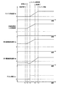
図9は、図8のフローチャートに示す制御作動を説明するためのタイムチャートであって、前記モータ走行中にアクセルペダルが踏み込まれ、自動変速部20のダウンシフト中に前記エンジン始動判断がなされた場合の例である。この図9では、上から順にエンジン回転速度NE、自動変速部20の入力回転速度、第2電動機回転速度NM2、第1電動機回転速度NM1、アクセル開度Accのタイムチャートとなっており、本実施例では自動変速部20の入力回転速度と第2電動機回転速度NM2とは同一である。 FIG. 9 is a time chart for explaining the control operation shown in the flowchart of FIG. 8, in which the accelerator pedal is depressed during the running of the motor, and the engine start determination is made during the downshift of the automatic transmission unit 20. This is an example. In FIG. 9, the engine rotation speed N E , the input rotation speed of the automatic transmission unit 20, the second motor rotation speed N M2 , the first motor rotation speed N M1 , and the accelerator opening Acc are shown in order from the top. In this embodiment, the input rotation speed of the automatic transmission unit 20 and the second motor rotation speed N M2 are the same.

図9のtA1時点は、図7に示すような変速マップに基づいて電子制御装置80において自動変速部20の変速をすべきか否かの判断である変速判断が行われたことを示している。 The time point t A1 in FIG. 9 indicates that a shift determination, which is a determination as to whether or not to shift the automatic transmission unit 20, should be performed in the electronic control unit 80 based on the shift map as shown in FIG. .

A2時点は、自動変速部20の変速を指令する変速出力が油圧制御回路70へ出されたことを示している。具体的には、自動変速部20のダウンシフトを指令する変速出力が出されている。この変速出力により、tA2時点から自動変速部20の変速が開始され、自動変速部20のダウンシフトを成立させるように第2電動機回転速度NM2すなわち自動変速部20の入力回転速度が引き上げられている。また、tA2時点ではエンジン8はその回転抵抗により回転していないので、第2電動機回転速度NM2の上昇と動力分配機構16の差動作用とによって、自由回転状態にある第1電動機M1はtA2時点から第2電動機M2とは逆方向にその回転速度NM1を増している。 The time point t A2 indicates that the shift output commanding the shift of the automatic transmission unit 20 is output to the hydraulic control circuit 70. Specifically, a shift output that instructs a downshift of the automatic transmission unit 20 is output. Due to this shift output, the shift of the automatic transmission unit 20 is started from time t A2 , and the second motor rotation speed NM2, that is, the input rotation speed of the automatic transmission unit 20 is increased so as to establish a downshift of the automatic transmission unit 20. ing. Further, since the engine 8 is not rotating due to its rotational resistance at the time t A2 , the first electric motor M1 in the free rotation state is caused by the increase in the second electric motor rotational speed N M2 and the differential action of the power distribution mechanism 16. The rotational speed N M1 is increased in the direction opposite to that of the second electric motor M2 from time t A2 .

A3時点は、アクセルペダルが踏み込まれたこと、すなわち、アクセル開度Accが大きくなったことを示している。このアクセル開度Accの増大により車両状態が図7のモータ走行領域からエンジン走行領域へと変化し、電子制御装置80において前記エンジン始動判断がなされている。そうすると図8のSA1にて肯定的な判定がなされ、かつ、図8のSA3にて自動変速部20がダウンシフト中である旨を肯定する判定がなされたので、図9のtA3時点から第1電動機回転速度NM1が第2電動機M2と同じ回転方向に引き上げられ、それによりエンジン始動のためエンジン回転速度NEが上昇させられている。なお、図9には示されていないが、tA3時点からエンジン回転速度NEの上昇に伴いエンジン8の回転抵抗が第2電動機回転速度NM2を押し下げる方向に働くので、tA3時点から第2電動機トルクTM2は増大されている。 At time t A3 , the accelerator pedal is depressed, that is, the accelerator opening Acc is increased. Due to the increase in the accelerator opening Acc, the vehicle state changes from the motor travel region in FIG. 7 to the engine travel region, and the engine start determination is made in the electronic control unit 80. Then the positive determination at SA1 in Fig. 8 made, and, because the determination of the automatic shifting portion 20 at SA3 in FIG. 8 affirms the effect that downshift has been made, the from time t A3 in FIG. 9 1 electric motor speed N M1 is raised in the same rotational direction as the second electric motor M2, so that by that the engine rotational speed N E for starting the engine is raised. Although not shown in FIG. 9, since the rotational resistance of the engine 8 with the time t A3 to increase in the engine rotational speed N E acts in a direction to push down the second-motor rotation speed N M2, the first from time t A3 2 The motor torque T M2 is increased.

A4時点は、自動変速部20の変速が終了したことを示している。従って、tA4時点以降では自動変速部20は非変速状態となり、車速Vに対応してtA4時点から第2電動機回転速度NM2すなわち自動変速部20の入力回転速度が一定になっている。但し、tA4時点では未だエンジンは始動されていないので、第1電動機回転速度NM1の引き上げによるエンジン回転速度NEの上昇は継続している。 The time t A4 indicates that the shift of the automatic transmission unit 20 has been completed. Accordingly, after the time t A4 , the automatic transmission unit 20 is in a non-shifting state, and the second motor rotation speed N M2, that is, the input rotation speed of the automatic transmission unit 20 is constant from the time t A4 corresponding to the vehicle speed V. However, still the engine at t A4 point because it is not started, the increase in the engine rotational speed N E by raising the first electric motor speed N M1 is continuing.

A5時点は、エンジン8の完爆、すなわち、エンジン回転速度NEがエンジン始動回転速度NE1に達し図9のSA7にて肯定的な判定がなされ図9のSA8にてエンジン点火が実施されたことを示している。なお、自動変速部20の変速終了による変速ショックとエンジン始動ショックとが重なることを避けるため、tA4時点とtA5時点との間の時間差が所定時間以上になるようにエンジン始動時期が決定されてもよい。 t A5 time, complete explosion of the engine 8, namely, engine ignition at SA8 of positive determination is made Figure 9 at SA7 engine rotational speed N E reaches the engine starting rotational speed NE1 9 is performed It is shown that. Note that the engine start timing is determined so that the time difference between the time t A4 and the time t A5 is equal to or greater than a predetermined time in order to avoid the overlap of the shift shock due to the end of the shift of the automatic transmission unit 20 and the engine start shock. May be.

図10は、図8のフローチャートに示す本実施例の制御作動と、従来の制御作動、すなわち自動変速部20の変速中はエンジン始動制御を禁止しその変速終了後にエンジン始動のためエンジン回転速度NEの上昇を開始する制御作動とを比較するためのタイムチャートであって、コースト走行時において前記モータ走行中にアクセルペダルが踏み込まれ、第2速から第1速への自動変速部20のダウンシフト中に前記エンジン始動判断がなされた場合の例である。そして、図10のtB1乃至tB4は図9のtA2乃至tA5にそれぞれ対応している。以下、その相違点について主に説明する。 FIG. 10 shows the control operation of the present embodiment shown in the flowchart of FIG. 8 and the conventional control operation, that is, engine start control is prohibited during the shift of the automatic transmission unit 20, and the engine speed N for engine start after the end of the shift. It is a time chart for comparing with the control operation which starts the rise of E , Comprising: The accelerator pedal is stepped on during the said motor driving | running | working at the time of coast driving | running | working, and the automatic transmission part 20 down from 2nd speed to 1st speed This is an example when the engine start determination is made during a shift. Then, t B1 to t B4 in FIG. 10 respectively correspond to t A2 or t A5 of FIG. Hereinafter, the difference will be mainly described.

B2時点では、アクセル開度Accの増大により車両状態が図7のモータ走行領域からエンジン走行領域へと変化し、電子制御装置80において前記エンジン始動判断がなされたので、本実施例では図9と同様に、図10のtB2時点から第1電動機回転速度NM1が第2電動機M2と同じ回転方向に引き上げられ、それによりエンジン始動のためエンジン回転速度NEが上昇させられている。一方、従来の制御作動ではエンジン始動のためエンジン回転速度NEの上昇は自動変速部20の変速中には行われないので、図10に破線で示されるように、第1電動機M1は第2電動機M2とは逆方向にその回転速度NM1を増大させ続け、エンジン回転速度NEは零を維持する。 At time t B2 , the vehicle state changes from the motor travel region of FIG. 7 to the engine travel region due to the increase in the accelerator opening Acc, and the engine start determination is made in the electronic control unit 80. Therefore, in this embodiment, FIG. similar to the first electric motor speed N M1 from t B2 point in FIG. 10 is pulled in the same direction of rotation as the second electric motor M2, so that by that the engine rotational speed N E for starting the engine is raised. On the other hand, in the conventional control operation, the engine rotation speed NE is not increased during the shift of the automatic transmission unit 20 because the engine is started. Therefore, as shown by the broken line in FIG. the electric motor M2 continues to increase its rotational speed N M1 in the reverse direction, the engine rotational speed N E is maintained at zero.

B3時点は、自動変速部20の変速が終了したことを示している。従って従来の制御作動では、図10に破線で示されるように、tB3時点から第1電動機回転速度NM1が第2電動機M2と同じ回転方向に引き上げられ、それによりエンジン始動のためエンジン回転速度NEが上昇させられている。なお、自動変速部20の変速開始を示すtB1時点から自動変速部20の変速終了を示すtB3時点まではその変速動作により自動変速部20内の動力伝達経路が遮断される。言い換えると、自動変速部20の入力軸である伝達部材18に連結された差動部11のリング軸が駆動輪34に拘束されていない状態すなわちフリー状態となっている。 The time point t B3 indicates that the shift of the automatic transmission unit 20 has been completed. Therefore, in the conventional control operation, as shown by the broken line in FIG. 10, the first motor rotation speed N M1 is increased in the same rotation direction as that of the second motor M2 from the time point t B3 , thereby the engine rotation speed for starting the engine. N E is raised. The power transmission path in the automatic transmission unit 20 is interrupted by the shifting operation from the time point t B1 indicating the start of shifting of the automatic transmission unit 20 to the time point t B3 indicating the end of shifting of the automatic transmission unit 20. In other words, the ring shaft of the differential unit 11 connected to the transmission member 18 that is the input shaft of the automatic transmission unit 20 is not restrained by the drive wheels 34, that is, is in a free state.

B4時点は、本実施例におけるエンジン8の完爆を示しているが、従来の制御作動においてはtB4時点では未だエンジン8の完爆に至っておらず、従来の制御作動はtB5時点でエンジン8の完爆に至っている。すなわち、図10のタイムチャートによれば、従来の制御作動と比較して本実施例はtB5時点からtB4時点にまでエンジン完爆に至るまでの所要時間が短縮され応答性が向上いていると言える。 The time point t B4 indicates the complete explosion of the engine 8 in the present embodiment. However, in the conventional control operation, the complete explosion of the engine 8 has not yet been reached at the time point t B4 , and the conventional control operation is performed at the time point t B5 . Engine 8 has been completely detonated. That is, according to the time chart of FIG. 10, the present embodiment as compared with the conventional control operation is had required time is shortened response characteristic is improved up to the complete explosion of the engine from t B5 point to a t B4 time It can be said.

図11は、図10の時間軸(横軸)上の各期間である〔1〕乃至〔4〕及び〔4’〕における第1電動機M1、エンジン8、第2電動機M2の各相対回転速度を説明する共線図であって、図10の〔1〕乃至〔4〕及び〔4’〕と図11の〔1〕乃至〔4〕及び〔4’〕とはそれぞれ対応している。なお、図11の〔3−1〕は従来の制御作動を示し、図11の〔3−2〕は本実施例を示し、図11の〔1〕,〔2〕,〔4〕,〔4’〕の共線図は本実施例と従来の制御作動との両方を示している。   FIG. 11 shows the relative rotational speeds of the first electric motor M1, the engine 8, and the second electric motor M2 in [1] to [4] and [4 ′] which are each period on the time axis (horizontal axis) of FIG. FIG. 10 is an alignment chart to be described, and [1] to [4] and [4 ′] in FIG. 10 correspond to [1] to [4] and [4 ′] in FIG. In addition, [3-1] in FIG. 11 shows a conventional control operation, [3-2] in FIG. 11 shows this embodiment, and [1], [2], [4], [4] in FIG. The nomogram of '] shows both the present embodiment and the conventional control operation.

図11〔1〕の共線図は図10のtB1時点までの状態を示すものであり、自動変速部20(図11中に「AT」として示す)は非変速中であるので自動変速部20内の動力伝達経路は連結状態すなわちクラッチ等の係合状態である。アクセル開度Accが零のコースト走行中であるので第2電動機M2は発電機として機能し、図11〔1〕の矢印TR1のように第2電動機M2はその回転速度NM2を下げる方向にトルクを発生している。なお、直線LS1と3本の縦軸との交点はそれぞれ第1電動機M1、エンジン8、第2電動機M2の回転速度を示しており、破線LSと上記3本の縦軸との交点はそれぞれエンジン完爆後であって自動変速部20の変速後すなわち第1速での第1電動機M1、エンジン8、第2電動機M2の回転速度を示している。 The collinear diagram of FIG. 11 [1] shows the state up to the time point t B1 of FIG. 10, and the automatic transmission unit 20 (shown as “AT” in FIG. 11) is not shifting, so the automatic transmission unit The power transmission path in 20 is in a connected state, that is, in an engaged state such as a clutch. The second electric motor M2 functions as a generator so the accelerator opening Acc is in coasting zero, the second electric motor M2 as indicated by the arrow T R1 in FIG. 11 (1) in the direction of reducing the rotational speed N M2 Torque is generated. The intersections of the straight line L S1 and the three vertical axes indicate the rotational speeds of the first electric motor M1, the engine 8, and the second electric motor M2, respectively. The intersections of the broken line L S and the three vertical axes are The rotation speeds of the first electric motor M1, the engine 8, and the second electric motor M2 after the engine complete explosion and after the shift of the automatic transmission unit 20, that is, the first speed are shown.

図11〔2〕の共線図は図10のtB1時点からtB2時点までの状態を示すものであり、自動変速部20は変速中であるので自動変速部20内の動力伝達経路は遮断状態すなわちクラッチ等が開放されたフリー状態である。第2速から第1速への自動変速部20のダウンシフトを成立させるため、図11〔2〕の矢印TR2のように第2電動機M2はトルクを出力し自動変速部20の入力回転速度である第2電動機回転速度NM2を上昇させている。なお、直線LS2と3本の縦軸との交点はそれぞれ第1電動機M1、エンジン8、第2電動機M2の回転速度を示している。 Alignment chart of FIG. 11 [2] are those indicating the state of the t B1 point in FIG. 10 to t B2 point, the automatic shifting portion 20 is under shifting power transmitting path of the automatic shifting portion 20 is shut off This is a free state in which the clutch or the like is released. Order to establish the down-shift of the automatic transmission portion 20 to the second speed to the first speed, the input rotational speed of the second electric motor M2 is the automatic shifting portion 20 to output the torque as indicated by an arrow T R2 in FIG. 11 (2) The second motor rotation speed N M2 is increased. Note that the intersections of the straight line L S2 and the three vertical axes indicate the rotational speeds of the first electric motor M1, the engine 8, and the second electric motor M2, respectively.

図11〔3−1〕の共線図は従来の制御作動における図10のtB2時点からtB3時点までの状態を示すものであり、自動変速部20は変速中であるので自動変速部20内の動力伝達経路はフリー状態を継続し、自動変速部20の上記ダウンシフトを成立させるため、第2電動機回転速度NM2を上昇させるように第2電動機トルクTM2の出力は継続している。なお、図11〔3−1〕の矢印TR3は第2電動機トルクTM2を示し、直線LS3-1と3本の縦軸との交点はそれぞれ第1電動機M1、エンジン8、第2電動機M2の回転速度を示している。 11 collinear chart of [3-1] are those indicating the state of the t B2 point in FIG. 10 in the conventional control operation until t B3 point, the automatic shifting portion 20 so the automatic shifting portion 20 is under shifting The internal power transmission path continues to be in a free state, and in order to establish the downshift of the automatic transmission unit 20, the output of the second motor torque T M2 is continued so as to increase the second motor rotation speed N M2 . . Arrows T R3 of FIG. 11 (3-1) represents a second electric motor torque T M2, the first electric motor M1 respectively intersection of the straight line L S3-1 and the three vertical axes of the engine 8, the second electric motor The rotation speed of M2 is shown.

図11〔3−2〕の共線図は本実施例における図10のtB2時点からtB3時点までの状態を示すものであり、自動変速部20は変速中であるので自動変速部20内の動力伝達経路はフリー状態を継続し、自動変速部20の上記ダウンシフトを成立させるため、第2電動機回転速度NM2を上昇させるように矢印TR4で示される第2電動機トルクTM2が出力されている。そして、図10のtB2時点で前記エンジン始動判断がなされたので矢印TR5で示される第1電動機トルクTM1の出力と矢印TR4で示される第2電動機トルクTM2の出力とによりエンジン回転速度NEが上昇させられている。ここで、第2電動機トルクTM2により第2電動機回転速度NM2の上昇を維持しつつ矢印TR6で示されるエンジン8の回転抵抗に対抗するため、矢印TR4で示される第2電動機トルクTM2は上記ダウンシフト成立のため第2電動機回転速度NM2を上昇させるトルクと上記エンジン8の回転抵抗に対抗する反力トルクとを合わせたトルクであり、前記矢印TR3で示される第2電動機トルクTM2より大きいトルクとなる。なお、直線LS3-2と3本の縦軸との交点はそれぞれ第1電動機M1、エンジン8、第2電動機M2の回転速度を示している。 The collinear diagram of FIG. 11 [3-2] shows the state from the time point t B2 to the time point t B3 in FIG. 10 in the present embodiment. Since the automatic transmission unit 20 is shifting, the automatic transmission unit 20 In order to continue the free state and establish the downshift of the automatic transmission unit 20, the second motor torque T M2 indicated by the arrow TR 4 is output so as to increase the second motor rotation speed N M2. Has been. Since the engine start determination is made at time t B2 in FIG. 10, the engine rotation is determined by the output of the first motor torque T M1 indicated by the arrow T R5 and the output of the second motor torque T M2 indicated by the arrow T R4. The speed NE is increased. In this case, in order to counteract rotational resistance of the engine 8 indicated by arrow T R6 by the second electric motor torque T M2 while maintaining the increase in the second-motor rotation speed N M2, the second motor torque T shown by the arrow T R4 M2 is a torque obtained by combining a torque for increasing the second motor rotational speed NM2 and a reaction torque against the rotational resistance of the engine 8 to establish the downshift, and the second motor indicated by the arrow TR3. Torque becomes larger than T M2 . Note that the intersections of the straight line L S3-2 and the three vertical axes indicate the rotational speeds of the first electric motor M1, the engine 8, and the second electric motor M2, respectively.

図11〔4〕〔4’〕の共線図は図10のtB3時点からtB4時点まで又はtB3時点からtB5時点までの状態を示すものであり、自動変速部20の変速は終了したので自動変速部20内の動力伝達経路は前記係合状態であり、車速V(駆動輪34)に拘束される第2電動機回転速度NM2は上昇させられないが、エンジン始動のために第1電動機回転速度NM1を上昇させてエンジン回転速度NEを上昇させるように、矢印TR9で示されるエンジン8の回転抵抗に対抗する矢印TR7で示される第2電動機トルクTM2と矢印TR8で示される第1電動機トルクTM1とが出力されている。従って、矢印TR7で示される第2電動機トルクTM2は、走行のための駆動力と上記エンジン8の回転抵抗に対抗する反力トルクとを合わせたトルクである。なお、直線LS4と3本の縦軸との交点はそれぞれ第1電動機M1、エンジン8、第2電動機M2の回転速度を示している。 11 (4) the alignment chart of [4 '] are those showing the state until t B5 time from t B3 or t B3 time from time to t B4 point in FIG. 10, the shifting of the automatic transmission portion 20 terminates Therefore, the power transmission path in the automatic transmission unit 20 is in the engaged state, and the second motor rotation speed NM2 restrained by the vehicle speed V (drive wheel 34) cannot be increased, but the first speed is required to start the engine. The second motor torque T M2 and the arrow T indicated by the arrow T R7 that oppose the rotational resistance of the engine 8 indicated by the arrow T R9 so that the motor rotation speed N M1 is increased and the engine rotation speed N E is increased. A first motor torque T M1 indicated by R8 is output. Accordingly, the second electric motor torque T M2 indicated by the arrow TR 7 is a torque obtained by combining the driving force for traveling and the reaction force torque that opposes the rotational resistance of the engine 8. The first electric motor M1 respectively intersection between the straight line L S4 3 present the longitudinal axis of the engine 8 shows a rotational speed of the second electric motor M2.

本実施例の電子制御装置80には次のような効果(1)乃至(6)がある。(1)エンジン始動手段94は、自動変速部20が非変速中である場合のエンジン8の始動方法に対して、自動変速部20が変速中である場合のエンジン8の始動方法を変更してエンジン8の始動を行うので、エンジン8の始動をするための動作が自動変速部20の変速動作に影響することを軽減することが可能であり、また、自動変速部20の変速中にエンジン8の始動をするための動作が開始され得るため、その動作が自動変速部20の変速終了後に開始される場合など、その動作と上記変速とが並行して行われない場合と比較して、運転者の加速要求に対する応答性を向上させることができる。   The electronic control device 80 of this embodiment has the following effects (1) to (6). (1) The engine starting means 94 changes the starting method of the engine 8 when the automatic transmission unit 20 is shifting, compared to the starting method of the engine 8 when the automatic transmission unit 20 is not shifting. Since the engine 8 is started, it is possible to reduce the influence of the operation for starting the engine 8 on the shift operation of the automatic transmission unit 20, and the engine 8 during the shift of the automatic transmission unit 20 can be reduced. Since the operation for starting the vehicle can be started, the operation is started after the end of the shift of the automatic transmission unit 20, compared with the case where the operation and the above shift are not performed in parallel. It is possible to improve the responsiveness to a person's acceleration request.

(2)自動変速部20の非変速中は第2電動機M2を使用せず第1電動機M1を使用して、エンジン8を始動させるためにエンジン回転速度NEが上昇させられるようにしてもよく、そのようにした場合には、第1電動機M1及び第2電動機M2の両方を同時に使用する場合と比較してエンジン回転速度NEを上昇させる制御が容易であり、自動変速部20の非変速中は電子制御装置80の制御負荷を軽減できる。 (2) The engine speed NE may be increased in order to start the engine 8 using the first electric motor M1 without using the second electric motor M2 while the automatic transmission unit 20 is not shifting. , in such a case, compared with the case of using both the first and second electric motors M1 and M2 simultaneously is easy to control to increase the engine rotational speed N E, the non-shifting of the automatic shifting portion 20 During this, the control load of the electronic control unit 80 can be reduced.

(3)自動変速部20の変速中は、第1電動機M1及び第2電動機M2の両方を使用して、エンジン8を始動させるためにエンジン回転速度NEが上昇させられるので、エンジン8の始動のためにエンジン回転速度NEを上昇させることが自動変速部20の変速中に可能であり、そのエンジン8の始動を早期に行うことで運転者の加速要求に対する応答性を向上させることが可能である。 (3) Since the engine speed NE is increased to start the engine 8 using both the first electric motor M1 and the second electric motor M2 during the shift of the automatic transmission unit 20, the engine 8 is started. It is possible during the shift of the engine speed N E automatic shifting portion 20 to increase the for, can improve the responsiveness to driver's acceleration request by performing starting of the engine 8 in an early stage It is.

(4)エンジン8を始動するためにエンジン回転速度NEを上昇させる場合には、自動変速部20が非変速中である場合の第2電動機トルクTM2に対して、自動変速部20が変速中である場合の第2電動機トルクTM2が変更されるので、エンジン8の始動をするための動作が自動変速部20の変速動作に影響することを軽減することが可能であり、また、自動変速部20の変速中にエンジン8の始動をするための動作が開始され得るため、その動作が自動変速部20の変速終了後に開始される場合など、その動作と上記変速とが並行して行われない場合と比較して、運転者の加速要求に対する応答性を向上させることができる。 (4) When the engine speed NE is increased in order to start the engine 8, the automatic transmission unit 20 changes the speed with respect to the second motor torque T M2 when the automatic transmission unit 20 is not shifting. Since the second electric motor torque T M2 when the engine is in the middle is changed, it is possible to reduce the influence of the operation for starting the engine 8 on the speed change operation of the automatic speed change unit 20, and Since the operation for starting the engine 8 can be started during the shift of the transmission unit 20, the operation and the above-described shift are performed in parallel when the operation is started after the shift of the automatic transmission unit 20 is completed. Responsiveness to the driver's acceleration request can be improved as compared with the case where the driver does not.

(5)自動変速部20の変速中は自動変速部20の非変速中よりも第2電動機トルクTM2が大きくなるように変更されるので、自動変速部20が変速中であるか否かに関わらず、エンジン8の始動のためにエンジン回転速度NEを上昇させることが可能であり、運転者の加速要求に対する応答性の向上を図り得る。 (5) Since during the shifting of the automatic shifting portion 20 is changed to the second electric motor torque T M2 than the non-shifting of the automatic shifting portion 20 increases, whether crab automatic shifting portion 20 is under shifting regardless, it is possible to increase the engine rotation speed N E for start-up of the engine 8, may aim to improve the response to the driver's acceleration demand.

(6)差動部11は、第1電動機M1の運転状態が制御されることにより無段変速機(無段変速機構)として作動するので、差動部11から出力される駆動トルクを滑らかに変化させることが可能である。   (6) Since the differential unit 11 operates as a continuously variable transmission (continuously variable transmission mechanism) by controlling the operating state of the first electric motor M1, the drive torque output from the differential unit 11 is smoothly smoothed. It is possible to change.

以上、本発明の実施例を図面に基づいて詳細に説明したが、これはあくまでも一実施形態であり、本発明は当業者の知識に基づいて種々の変更、改良を加えた態様で実施することができる。   As mentioned above, although the Example of this invention was described in detail based on drawing, this is an embodiment to the last, and this invention is implemented in the aspect which added various change and improvement based on the knowledge of those skilled in the art. Can do.

例えば、本実施例では、第1電動機M1及び第2電動機M2は差動部11に備えられているが、第1電動機M1及び第2電動機M2が差動部11の一部である必要は特になく、例えば、第1電動機M1及び第2電動機M2が差動部11とは別個に変速機構10に備えられていてもよい。   For example, in the present embodiment, the first electric motor M1 and the second electric motor M2 are provided in the differential unit 11, but it is particularly necessary that the first electric motor M1 and the second electric motor M2 are part of the differential unit 11. For example, the first electric motor M <b> 1 and the second electric motor M <b> 2 may be provided in the transmission mechanism 10 separately from the differential unit 11.

また本実施例の差動部11は、例えば第1回転要素RE1と第2回転要素RE2との間の相対回転を制限もしくは禁止できるクラッチ等の差動制限装置を備えていてもよい。そのようにしてエンジン始動のためエンジン回転速度NEを上昇させる場合には、上記差動制限装置により第1回転要素RE1と第2回転要素RE2との間の相対回転を制限もしくは禁止して第1乃至第3回転要素RE1,RE2,RE3が一体回転する非差動状態とすることで、第1電動機M1又は第2電動機M2の何れか一方を使用しエンジン始動のためにエンジン回転速度NEを上昇させることができ、例えば、第1電動機M1を使用せず第2電動機M2を制御してエンジン回転速度NEを上昇させることができ、第1電動機M1及び第2電動機M2の両方を使用する場合と比較して電子制御装置80の制御負荷の軽減を図り得る。 Further, the differential section 11 of the present embodiment may include a differential limiting device such as a clutch that can limit or prohibit relative rotation between the first rotating element RE1 and the second rotating element RE2, for example. Thus, when the engine speed NE is increased for starting the engine, the differential limiting device restricts or prohibits the relative rotation between the first rotating element RE1 and the second rotating element RE2, and thereby By setting the first to third rotating elements RE1, RE2, and RE3 in a non-differential state in which the rotating elements RE1, RE2, and RE3 rotate integrally, the engine rotational speed N E is used to start the engine using either the first electric motor M1 or the second electric motor M2. It can be raised, for example, by controlling the second electric motor M2 without using the first electric motor M1 can increase the engine rotational speed N E, using both the first and second electric motors M1 and M2 The control load of the electronic control unit 80 can be reduced as compared with the case where it is performed.

また、自動変速部20の変速中にエンジン始動が行われる場合には、出来るだけ早い駆動トルクの上昇を運転者に期待されているので、上記変速とエンジン始動とが独立して実施される場合と比較して、第1電動機M1及び第2電動機M2によるエンジン回転速度NEの上昇を早めると共に、変速終了時期及びエンジン点火時期が早められるようにして応答性の向上が図られてもよい。 Further, when the engine is started during the shift of the automatic transmission unit 20, the driver is expected to increase the drive torque as quickly as possible, and therefore the shift and the engine start are performed independently. and compared, with hasten the rise of the engine speed N E by the first electric motor M1 and the second electric motor M2, improved responsiveness as shift end timing and the engine ignition timing is advanced can be achieved.

また本実施例では、第2電動機M2は伝達部材18に直接連結されているが、第2電動機M2の連結位置はそれに限定されず、エンジン8又は伝達部材18から駆動輪34までの間の動力伝達経路に直接的或いは変速機、遊星歯車装置、係合装置等を介して間接的に連結されていてもよい。   In the present embodiment, the second electric motor M2 is directly connected to the transmission member 18, but the connection position of the second electric motor M2 is not limited thereto, and the power between the engine 8 or the transmission member 18 and the drive wheels 34 is not limited thereto. You may connect with the transmission path directly or indirectly through a transmission, a planetary gear apparatus, an engagement apparatus, etc.

また本実施例では、差動部11はそのギヤ比γ0が最小値γ0minから最大値γ0maxまで連続的に変化させられる電気的な無段変速機として機能するものであったが、たとえば差動部11の変速比γ0を連続的ではなく差動作用を利用して敢えて段階的に変化させるものであっても本発明は適用することができる。   In this embodiment, the differential unit 11 functions as an electric continuously variable transmission whose gear ratio γ0 is continuously changed from the minimum value γ0min to the maximum value γ0max. The present invention can be applied even if the gear ratio γ0 of 11 is changed not in a continuous manner but in a stepwise manner using a differential action.

また本実施例の動力分配機構16では、差動部キャリヤCA0がエンジン8に連結され、差動部サンギヤS0が第1電動機M1に連結され、差動部リングギヤR0が伝達部材18に連結されていたが、それらの連結関係は、必ずしもそれに限定されるものではなく、エンジン8、第1電動機M1、伝達部材18は、差動部遊星歯車装置24の3要素CA0、S0、R0のうちのいずれと連結されていても差し支えない。   In the power distribution mechanism 16 of the present embodiment, the differential carrier CA0 is connected to the engine 8, the differential sun gear S0 is connected to the first electric motor M1, and the differential ring gear R0 is connected to the transmission member 18. However, the connection relationship is not necessarily limited thereto, and the engine 8, the first electric motor M1, and the transmission member 18 may be any one of the three elements CA0, S0, and R0 of the differential planetary gear unit 24. It can be connected to

また本実施例では、エンジン8は入力軸14と直結されていたが、たとえばギヤ、ベルト等を介して作動的に連結されておればよく、共通の軸心上に配置される必要もない。   In the present embodiment, the engine 8 is directly connected to the input shaft 14, but may be operatively connected, for example, via a gear, a belt, or the like, and does not need to be disposed on a common axis.

また本実施例では、第1電動機M1および第2電動機M2は、入力軸14に同心に配置されて第1電動機M1は差動部サンギヤS0に連結され第2電動機M2は伝達部材18に連結されていたが、必ずしもそのように配置される必要はなく、たとえばギヤ、ベルト、減速機等を介して作動的に第1電動機M1は差動部サンギヤS0に連結され、第2電動機M2は伝達部材18に連結されていてもよい。   In this embodiment, the first electric motor M1 and the second electric motor M2 are arranged concentrically with the input shaft 14, the first electric motor M1 is connected to the differential sun gear S0, and the second electric motor M2 is connected to the transmission member 18. However, the first motor M1 is operatively connected to the differential sun gear S0 via a gear, a belt, a speed reducer, etc., and the second motor M2 is a transmission member. 18 may be connected.

また本実施例では、第1クラッチC1や第2クラッチC2などの油圧式摩擦係合装置は、パウダー(磁紛)クラッチ、電磁クラッチ、噛合型のドグクラッチなどの磁紛式、電磁式、機械式係合装置から構成されていてもよい。たとえば電磁クラッチであるような場合には、油圧制御回路70は油路を切り換える弁装置ではなく電磁クラッチへの電気的な指令信号回路を切り換えるスイッチング装置や電磁切換装置等により構成される。   In this embodiment, the hydraulic friction engagement devices such as the first clutch C1 and the second clutch C2 are magnetic, electromagnetic, and mechanical such as powder (magnetic) clutch, electromagnetic clutch, and meshing dog clutch. You may be comprised from the engaging apparatus. For example, in the case of an electromagnetic clutch, the hydraulic control circuit 70 is configured by a switching device, an electromagnetic switching device, or the like that switches an electrical command signal circuit to the electromagnetic clutch, not a valve device that switches an oil passage.

また本実施例では、自動変速部20は伝達部材18を介して差動部11と直列に連結されていたが、入力軸14と平行にカウンタ軸が設けられてそのカウンタ軸上に同心に自動変速部20が配列されていてもよい。この場合には、差動部11と自動変速部20とは、たとえば伝達部材18としてカウンタギヤ対、スプロケットおよびチェーンで構成される1組の伝達部材などを介して動力伝達可能に連結される。   In this embodiment, the automatic transmission unit 20 is connected in series with the differential unit 11 via the transmission member 18. However, a counter shaft is provided in parallel with the input shaft 14 and automatically concentrically on the counter shaft. The transmission unit 20 may be arranged. In this case, the differential unit 11 and the automatic transmission unit 20 are coupled so as to be able to transmit power, for example, as a transmission member 18 via a pair of transmission members including a counter gear pair, a sprocket and a chain.

また、本実施例の差動機構として動力分配機構16は、たとえばエンジン8によって回転駆動されるピニオンと、そのピニオンに噛み合う一対のかさ歯車が第1電動機M1および伝達部材18(第2電動機M2)に作動的に連結された差動歯車装置であってもよい。   Further, the power distribution mechanism 16 as a differential mechanism of the present embodiment includes, for example, a pinion that is rotationally driven by the engine 8 and a pair of bevel gears that mesh with the pinion, the first electric motor M1 and the transmission member 18 (second electric motor M2). It may be a differential gear device operatively connected to the motor.

また、本実施例の動力分配機構16は、1組の遊星歯車装置から構成されていたが2以上の遊星歯車装置から構成されて、非差動状態(定変速状態)では3段以上の変速機として機能するものであってもよい。また、その遊星歯車装置はシングルピニオン型に限られたものではなくダブルピニオン型の遊星歯車装置であってもよい。また、このような2以上の遊星歯車装置から構成された場合においても、これらの遊星歯車装置の各回転要素にエンジン8、第1および第2電動機M1、M2、伝達部材18、構成によっては出力軸22が動力伝達可能に連結され、さらに遊星歯車装置の各回転要素に接続されたクラッチCおよびブレーキBの制御により有段変速と無段変速とが切り換えられるような構成であっも構わない。   Further, the power distribution mechanism 16 of the present embodiment is composed of one set of planetary gear devices, but is composed of two or more planetary gear devices, and in a non-differential state (constant speed change state), it has three or more speeds. It may function as a machine. The planetary gear device is not limited to a single pinion type, and may be a double pinion type planetary gear device. Even in the case where the planetary gear unit is composed of two or more planetary gear units, the engine 8, the first and second electric motors M1 and M2, the transmission member 18, and the output of each planetary gear unit depending on the configuration. The shaft 22 may be connected so as to be able to transmit power, and the stepped speed change and the stepless speed change may be switched by the control of the clutch C and the brake B connected to the rotating elements of the planetary gear device.

また、本実施例ではエンジン8と差動部11とが直接連結されているが、必ずしも直接連結される必要はなく、エンジン8と差動部11との間にクラッチを介して連結されていてもよい。   Further, in the present embodiment, the engine 8 and the differential unit 11 are directly coupled, but it is not always necessary to couple directly, and the engine 8 and the differential unit 11 are coupled via a clutch. Also good.

また、本実施例では、差動部11と自動変速部20とが直列接続されたような構成となっているが、特にこのような構成に限定されず、変速機構10全体として電気式差動を行う機能と、変速機構10全体として電気式差動による変速とは異なる原理で変速を行う機能とを備えた構成であれば本発明は適用可能であり、機械的に独立している必要はない。また、これらの配設位置や配設順序も特に限定されない。要するに、自動変速部20は、エンジン8から駆動輪34への動力伝達経路の一部を構成するように設けられておればよい。   In the present embodiment, the differential unit 11 and the automatic transmission unit 20 are connected in series. However, the present invention is not particularly limited to this configuration, and the transmission mechanism 10 as a whole is electrically differential. The present invention can be applied to any configuration that includes a function for performing gear shifting and a function for performing gear shifting on a principle different from that based on electrical differential as a whole of the speed change mechanism 10 and need not be mechanically independent. Absent. Further, the arrangement position and arrangement order of these are not particularly limited. In short, the automatic transmission unit 20 may be provided so as to constitute a part of the power transmission path from the engine 8 to the drive wheels 34.

また、第2電動機M2はエンジン8から駆動輪34までの動力伝達経路の一部を構成する伝達部材18に連結されているが、第2電動機M2がその動力伝達経路に連結されていることに加え、クラッチ等の係合要素を介して動力分配機構16にも連結可能とされており、第1電動機M1の代わりに第2電動機M2によって動力分配機構16の差動状態を制御可能とする変速機構10の構成であってもよい。   Further, the second electric motor M2 is connected to the transmission member 18 that constitutes a part of the power transmission path from the engine 8 to the drive wheels 34, but the second motor M2 is connected to the power transmission path. In addition, it is possible to connect to the power distribution mechanism 16 via an engagement element such as a clutch, and the speed change that enables the differential state of the power distribution mechanism 16 to be controlled by the second electric motor M2 instead of the first electric motor M1. The structure of the mechanism 10 may be used.

また、変速機構10において第1電動機M1と第2回転要素RE2とは直結されており、第2電動機M2と第3回転要素RE3とは直結されているが、第1電動機M1が第2回転要素RE2にクラッチ等の係合要素を介して連結され、第2電動機M2が第3回転要素RE3にクラッチ等の係合要素を介して連結されていてもよい。   In the speed change mechanism 10, the first electric motor M1 and the second rotating element RE2 are directly connected, and the second electric motor M2 and the third rotating element RE3 are directly connected, but the first electric motor M1 is the second rotating element. The second motor M2 may be connected to the RE2 via an engagement element such as a clutch, and the second electric motor M2 may be connected to the third rotating element RE3 via an engagement element such as a clutch.

また、自動変速部20は有段の自動変速機として機能する変速部であるが、無段のCVTであってもよい。   The automatic transmission unit 20 is a transmission unit that functions as a stepped automatic transmission, but may be a continuously variable CVT.

本発明の制御装置が適用されるハイブリッド車両用動力伝達装置の構成を説明する骨子図である。1 is a skeleton diagram illustrating a configuration of a power transmission device for a hybrid vehicle to which a control device of the present invention is applied. 図1のハイブリッド車両用動力伝達装置に備えられた自動変速部の変速作動とそれに用いられる油圧式摩擦係合装置の作動の組み合わせとの関係を説明する作動図表である。2 is an operation chart for explaining a relationship between a shift operation of an automatic transmission unit provided in the hybrid vehicle power transmission device of FIG. 1 and a combination of operations of a hydraulic friction engagement device used therefor. 図1のハイブリッド車両用動力伝達装置における各ギヤ段の相対回転速度を説明する共線図である。FIG. 2 is a collinear diagram illustrating a relative rotational speed of each gear stage in the hybrid vehicle power transmission device of FIG. 1. 図1のハイブリッド車両用動力伝達装置に設けられた電子制御装置の入出力信号を説明する図である。It is a figure explaining the input-output signal of the electronic controller provided in the power transmission device for hybrid vehicles of FIG. シフトレバーを備えた複数種類のシフトポジションを選択するために操作されるシフト操作装置の一例である。It is an example of the shift operation apparatus operated in order to select multiple types of shift positions provided with the shift lever. 図4の電子制御装置による制御機能の要部を説明する機能ブロック線図である。It is a functional block diagram explaining the principal part of the control function by the electronic controller of FIG. 図1のハイブリッド車両用動力伝達装置において、車速と出力トルクとをパラメータとする同じ二次元座標に構成された、自動変速部の変速判断の基となる予め記憶された変速線図の一例と、エンジン走行とモータ走行とを切り換えるためのエンジン走行領域とモータ走行領域との境界線を有する予め記憶された駆動力源切換線図の一例とを示す図であって、それぞれの関係を示す図でもある。In the hybrid vehicle power transmission apparatus of FIG. 1, an example of a pre-stored shift diagram that is based on the same two-dimensional coordinates using the vehicle speed and the output torque as parameters and is a basis for shift determination of the automatic transmission unit, It is a figure which shows an example of the driving force source switching diagram memorize | stored beforehand which has the boundary line of the engine running area | region and motor running area | region for switching engine driving | running | working and motor driving | running | working area, is there. 図4の電子制御装置の制御作動の要部すなわちモータ走行中にエンジン始動させるための制御作動を説明するフローチャートである。6 is a flowchart for explaining a main part of the control operation of the electronic control device of FIG. 図8のフローチャートに示す制御作動を説明するためのタイムチャートであって、モータ走行中にアクセルペダルが踏み込まれ、自動変速部のダウンシフト中にエンジン始動判断がなされた場合の例である。FIG. 9 is a time chart for explaining the control operation shown in the flowchart of FIG. 8, in which an accelerator pedal is depressed during running of the motor and an engine start determination is made during a downshift of the automatic transmission unit. 図8のフローチャートに示す本実施例の制御作動と、従来の制御作動、すなわち自動変速部の変速中はエンジン始動制御を禁止しその変速終了後にエンジン始動のためエンジン回転速度の上昇を開始する制御作動とを比較するためのタイムチャートであって、コースト走行時においてモータ走行中にアクセルペダルが踏み込まれ、第2速から第1速への自動変速部のダウンシフト中にエンジン始動判断がなされた場合の例である。The control operation of the present embodiment shown in the flowchart of FIG. 8 and the conventional control operation, that is, control for prohibiting engine start control during shifting of the automatic transmission and starting to increase engine rotational speed for engine start after the end of the shift. FIG. 5 is a time chart for comparing operation with an accelerator pedal being depressed during motor running during coast running, and an engine start determination is made during downshift of the automatic transmission unit from second speed to first speed. This is an example. 図10の時間軸(横軸)上の各期間である〔1〕乃至〔4〕及び〔4’〕における第1電動機、エンジン、第2電動機の各相対回転速度を説明する共線図である。FIG. 11 is a collinear diagram illustrating relative rotational speeds of the first electric motor, the engine, and the second electric motor in [1] to [4] and [4 ′] that are each period on the time axis (horizontal axis) of FIG. 10. .

符号の説明Explanation of symbols

8:エンジン
10:変速機構(ハイブリッド車両用動力伝達装置)
11:差動部(電気式差動部)
14:入力軸
16:動力分配機構(差動機構)
20:自動変速部(変速部)
80:電子制御装置(エンジン始動装置)
M1:第1電動機 M2:第2電動機
8: Engine 10: Transmission mechanism (power transmission device for hybrid vehicle)
11: Differential part (electrical differential part)
14: Input shaft 16: Power distribution mechanism (differential mechanism)
20: Automatic transmission unit (transmission unit)
80: Electronic control device (engine starter)
M1: first electric motor M2: second electric motor

Claims (7)

差動機構を有し、該差動機構に動力伝達可能に連結された第1電動機の運転状態が制御されることにより該差動機構の差動状態が制御される電気式差動部と、動力伝達経路の一部を構成し自動変速機として機能する変速部と、該動力伝達経路に連結された第2電動機とを備えたハイブリッド車両用動力伝達装置のエンジン始動装置であって、
該変速部が非変速中である場合のエンジンの始動方法に対して、該変速部が変速中である場合の該エンジンの始動方法を変更する
ことを特徴とするハイブリッド車両用動力伝達装置のエンジン始動装置。
An electric differential unit having a differential mechanism, and the differential state of the differential mechanism is controlled by controlling the operating state of the first electric motor coupled to the differential mechanism so as to transmit power; and An engine starter for a power transmission device for a hybrid vehicle, comprising: a transmission portion that constitutes a part of a power transmission path and functions as an automatic transmission; and a second electric motor coupled to the power transmission path,
An engine of a power transmission device for a hybrid vehicle, wherein the engine starting method when the transmission unit is shifting is changed with respect to the engine starting method when the transmission unit is not shifting. Starter.
前記電気式差動部の入力軸にエンジンが動力伝達可能に連結されており、
前記変速部の非変速中は、前記第1電動機と前記第2電動機とのいずれか1つを使用して、前記エンジンを始動させるために該エンジンの回転速度を上昇させる
ことを特徴とする請求項1に記載のハイブリッド車両用動力伝達装置のエンジン始動装置。
An engine is connected to the input shaft of the electric differential section so that power can be transmitted,
The non-shifting of the speed change unit uses one of the first electric motor and the second electric motor to increase the rotational speed of the engine in order to start the engine. Item 4. An engine starter for a hybrid vehicle power transmission device according to Item 1.
前記変速部の変速中は、前記第1電動機と前記第2電動機との両方を使用して、前記エンジンを始動させるために該エンジンの回転速度を上昇させる
ことを特徴とする請求項2に記載のハイブリッド車両用動力伝達装置のエンジン始動装置。
3. The engine according to claim 2, wherein both the first electric motor and the second electric motor are used to increase the rotational speed of the engine during the shifting of the transmission unit in order to start the engine. Engine starter for a hybrid vehicle power transmission device.
前記電気式差動部の入力軸にエンジンが動力伝達可能に連結されており、
前記変速部の変速中は、前記第1電動機と前記第2電動機との両方を使用して、前記エンジンを始動させるために該エンジンの回転速度を上昇させる
ことを特徴とする請求項1に記載のハイブリッド車両用動力伝達装置のエンジン始動装置。
An engine is connected to the input shaft of the electric differential section so that power can be transmitted,
2. The engine according to claim 1, wherein both the first electric motor and the second electric motor are used to increase the rotational speed of the engine during the shifting of the transmission unit in order to start the engine. Engine starter for a hybrid vehicle power transmission device.
差動機構を有し、該差動機構に動力伝達可能に連結された第1電動機の運転状態が制御されることにより該差動機構の差動状態が制御される電気式差動部と、動力伝達経路の一部を構成し自動変速機として機能する変速部と、該動力伝達経路に連結された第2電動機とを備えたハイブリッド車両用動力伝達装置のエンジン始動装置であって、
エンジンを始動するために該エンジンの回転速度を上昇させる場合には、前記変速部が非変速中である場合の前記第2電動機の出力トルクに対して、該変速部が変速中である場合の該第2電動機の出力トルクを変更する
ことを特徴とするハイブリッド車両用動力伝達装置のエンジン始動装置。
An electric differential unit having a differential mechanism, and the differential state of the differential mechanism is controlled by controlling the operating state of the first electric motor coupled to the differential mechanism so as to transmit power; and An engine starter for a power transmission device for a hybrid vehicle, comprising: a transmission portion that constitutes a part of a power transmission path and functions as an automatic transmission; and a second electric motor coupled to the power transmission path,
When the rotational speed of the engine is increased in order to start the engine, a case where the transmission unit is shifting with respect to an output torque of the second electric motor when the transmission unit is not shifting. An engine starter for a power transmission device for a hybrid vehicle, wherein the output torque of the second electric motor is changed.
前記変速部の変速中は該変速部の非変速中よりも前記第2電動機の出力トルクを大きくする
ことを特徴とする請求項5に記載のハイブリッド車両用動力伝達装置のエンジン始動装置。
6. The engine starter for a hybrid vehicle power transmission device according to claim 5, wherein the output torque of the second electric motor is set larger during shifting of the shifting unit than during non-shifting of the shifting unit.
前記電気式差動部は、前記第1電動機の運転状態が制御されることにより無段変速機構として作動する
ことを特徴とする請求項1乃至請求項6のいずれか1項に記載のハイブリッド車両用動力伝達装置のエンジン始動装置。
The hybrid vehicle according to any one of claims 1 to 6, wherein the electric differential unit operates as a continuously variable transmission mechanism by controlling an operation state of the first electric motor. Engine starter for power transmission equipment for automobiles.
JP2007180211A 2007-07-09 2007-07-09 Engine start-up device for power transmission device for hybrid car Pending JP2009012730A (en)

Priority Applications (4)

Application Number Priority Date Filing Date Title
JP2007180211A JP2009012730A (en) 2007-07-09 2007-07-09 Engine start-up device for power transmission device for hybrid car
US12/216,578 US8197384B2 (en) 2007-07-09 2008-07-08 Engine start-up device for hybrid vehicle power transmitting device
EP08252344.0A EP2014498B1 (en) 2007-07-09 2008-07-09 Engine start-up device for hybrid vehicle power transmitting device
CN2008101280042A CN101342902B (en) 2007-07-09 2008-07-09 Engine start-up device for hybrid vehicle power transmitting device

Applications Claiming Priority (1)

Application Number Priority Date Filing Date Title
JP2007180211A JP2009012730A (en) 2007-07-09 2007-07-09 Engine start-up device for power transmission device for hybrid car

Publications (1)

Publication Number Publication Date
JP2009012730A true JP2009012730A (en) 2009-01-22

Family

ID=40245059

Family Applications (1)

Application Number Title Priority Date Filing Date
JP2007180211A Pending JP2009012730A (en) 2007-07-09 2007-07-09 Engine start-up device for power transmission device for hybrid car

Country Status (2)

Country Link
JP (1) JP2009012730A (en)
CN (1) CN101342902B (en)

Cited By (2)

* Cited by examiner, † Cited by third party
Publication number Priority date Publication date Assignee Title
JP2015053782A (en) * 2013-09-06 2015-03-19 トヨタ自動車株式会社 Control device and vehicle using the same
CN113272194A (en) * 2019-01-18 2021-08-17 三菱自动车工业株式会社 Vehicle control device

Families Citing this family (17)

* Cited by examiner, † Cited by third party
Publication number Priority date Publication date Assignee Title
JP5527873B2 (en) * 2009-03-18 2014-06-25 株式会社エフ・シー・シー Power transmission device
JP5497316B2 (en) 2009-03-27 2014-05-21 ヤマハモーターパワープロダクツ株式会社 Inverter generator
CN102405165B (en) * 2010-04-09 2015-04-08 丰田自动车株式会社 Vehicle driving force control device
US8328687B2 (en) * 2010-07-09 2012-12-11 Ford Global Technologies, Llc Method for controlling an engine that may be automatically stopped
US8620505B2 (en) * 2011-10-14 2013-12-31 GM Global Technology Operations LLC Stand alone engine speed control at cold start for hybrid transmission
US8892289B2 (en) 2012-05-04 2014-11-18 Ford Global Technologies, Llc Methods and systems for operating a vehicle driveline
US8882634B2 (en) 2012-05-04 2014-11-11 Ford Global Technologies, Llc Methods and systems for operating a vehicle driveline responsive to external conditions
DE102013104516A1 (en) * 2012-05-04 2013-11-07 Ford Global Technologies, Llc Method for starting engine of hybrid vehicle system, involves starting rotation of stopped engine, if predicted desired rotational torque is larger than swelling deer moment amount according to gearbox upshift
US9068546B2 (en) 2012-05-04 2015-06-30 Ford Global Technologies, Llc Methods and systems for engine cranking
US9108632B2 (en) 2012-05-04 2015-08-18 Ford Global Technologies, Llc Methods and systems for operating a driveline clutch
US9278692B2 (en) 2012-05-04 2016-03-08 Ford Global Technologies, Llc Methods and systems for a four wheel drive vehicle driveline
US9656665B2 (en) 2012-05-04 2017-05-23 Ford Global Technologies, Llc Methods and systems for a driveline dual mass flywheel
US9039570B2 (en) 2012-05-04 2015-05-26 Ford Global Technologies, Llc Methods and systems for adjusting driveline disconnect clutch operation
US8998771B2 (en) 2012-05-04 2015-04-07 Ford Global Technologies, Llc Methods and systems for a vehicle driveline
US9650036B2 (en) 2012-05-04 2017-05-16 Ford Global Technologies, Llc Methods and systems for adjusting cylinder air charge
US9322380B2 (en) 2012-05-04 2016-04-26 Ford Global Technologies, Llc Methods and systems for engine starting during a shift
CN114909467B (en) * 2021-02-07 2024-04-12 广汽埃安新能源汽车有限公司 Vehicle upshift control method, device and storage medium

Citations (1)

* Cited by examiner, † Cited by third party
Publication number Priority date Publication date Assignee Title
JP2008265577A (en) * 2007-04-20 2008-11-06 Toyota Motor Corp Engine start control device for hybrid vehicle

Family Cites Families (5)

* Cited by examiner, † Cited by third party
Publication number Priority date Publication date Assignee Title
US6177734B1 (en) * 1998-02-27 2001-01-23 Isad Electronic Systems Gmbh & Co. Kg Starter/generator for an internal combustion engine, especially an engine of a motor vehicle
FR2875446B1 (en) * 2004-09-23 2007-02-23 Peugeot Citroen Automobiles Sa SYSTEM FOR MONITORING THE OPERATION OF HYBRID MOTORIZATION MEANS OF A MOTOR VEHICLE
JP4222349B2 (en) * 2005-08-25 2009-02-12 トヨタ自動車株式会社 Hybrid vehicle and control method thereof
CN1935552A (en) * 2005-09-23 2007-03-28 奇瑞汽车有限公司 Weak mixed power automobile power system
CN1986307A (en) * 2006-12-08 2007-06-27 奇瑞汽车有限公司 Engine on-off control method for mixed power automobile

Patent Citations (1)

* Cited by examiner, † Cited by third party
Publication number Priority date Publication date Assignee Title
JP2008265577A (en) * 2007-04-20 2008-11-06 Toyota Motor Corp Engine start control device for hybrid vehicle

Cited By (3)

* Cited by examiner, † Cited by third party
Publication number Priority date Publication date Assignee Title
JP2015053782A (en) * 2013-09-06 2015-03-19 トヨタ自動車株式会社 Control device and vehicle using the same
CN113272194A (en) * 2019-01-18 2021-08-17 三菱自动车工业株式会社 Vehicle control device
CN113272194B (en) * 2019-01-18 2023-08-04 三菱自动车工业株式会社 Control device for vehicle

Also Published As

Publication number Publication date
CN101342902A (en) 2009-01-14
CN101342902B (en) 2012-02-01

Similar Documents

Publication Publication Date Title
JP5267656B2 (en) Control device for vehicle power transmission device
JP5144805B2 (en) Control device for vehicle drive device
JP4501956B2 (en) Control device for drive device for hybrid vehicle
JP2009012730A (en) Engine start-up device for power transmission device for hybrid car
JP4329864B2 (en) Control device for vehicle power transmission device
JP4605256B2 (en) Control device for vehicle power transmission device
JP5018445B2 (en) Control device for vehicle power transmission device
JP5125199B2 (en) Engine start control device for hybrid vehicle
JP2008207690A (en) Control system of vehicular drive system
JP4683137B2 (en) Power transmission control device
JP2008105475A (en) Engine starter for hybrid vehicle
JP2010070008A (en) Apparatus for controllng vehicle driving device
JP5445306B2 (en) Gear position setting method for vehicle automatic transmission
JP2009280176A (en) Controller for vehicular power transmission device
JP2010143491A (en) Controller for vehicular power transmission device
JP2009149133A (en) Control apparatus for power transmission apparatus for vehicle
JP2009280177A (en) Controller for vehicular power transmission device
JP2010076544A (en) Control device for vehicle power transmission device
JP5195376B2 (en) Control device for vehicle drive device
JP4853410B2 (en) Control device for power transmission device for hybrid vehicle
JP2009012618A (en) Controller for power transmission device for hybrid vehicle
JP2010126094A (en) Apparatus for controlling power transmission device for vehicle
JP2009286187A (en) Control device for transmission system for vehicle
JP2010115980A (en) Controller of vehicle power transmission
JP2009166741A (en) Shift controller of vehicle power transmission system

Legal Events

Date Code Title Description
A621 Written request for application examination

Free format text: JAPANESE INTERMEDIATE CODE: A621

Effective date: 20091222

A131 Notification of reasons for refusal

Free format text: JAPANESE INTERMEDIATE CODE: A131

Effective date: 20110809

A521 Written amendment

Free format text: JAPANESE INTERMEDIATE CODE: A523

Effective date: 20111004

A131 Notification of reasons for refusal

Free format text: JAPANESE INTERMEDIATE CODE: A131

Effective date: 20120327

A521 Written amendment

Free format text: JAPANESE INTERMEDIATE CODE: A523

Effective date: 20120522

A02 Decision of refusal

Free format text: JAPANESE INTERMEDIATE CODE: A02

Effective date: 20120612