JP2009012461A - Ink jet print head and missing nozzle detection method - Google Patents
Ink jet print head and missing nozzle detection method Download PDFInfo
- Publication number
- JP2009012461A JP2009012461A JP2008145725A JP2008145725A JP2009012461A JP 2009012461 A JP2009012461 A JP 2009012461A JP 2008145725 A JP2008145725 A JP 2008145725A JP 2008145725 A JP2008145725 A JP 2008145725A JP 2009012461 A JP2009012461 A JP 2009012461A
- Authority
- JP
- Japan
- Prior art keywords
- temperature sensing
- nozzle
- heater
- temperature
- ink
- Prior art date
- Legal status (The legal status is an assumption and is not a legal conclusion. Google has not performed a legal analysis and makes no representation as to the accuracy of the status listed.)
- Pending
Links
Images


Classifications
-
- B—PERFORMING OPERATIONS; TRANSPORTING
- B41—PRINTING; LINING MACHINES; TYPEWRITERS; STAMPS
- B41J—TYPEWRITERS; SELECTIVE PRINTING MECHANISMS, i.e. MECHANISMS PRINTING OTHERWISE THAN FROM A FORME; CORRECTION OF TYPOGRAPHICAL ERRORS
- B41J2/00—Typewriters or selective printing mechanisms characterised by the printing or marking process for which they are designed
- B41J2/005—Typewriters or selective printing mechanisms characterised by the printing or marking process for which they are designed characterised by bringing liquid or particles selectively into contact with a printing material
- B41J2/01—Ink jet
- B41J2/015—Ink jet characterised by the jet generation process
- B41J2/04—Ink jet characterised by the jet generation process generating single droplets or particles on demand
- B41J2/045—Ink jet characterised by the jet generation process generating single droplets or particles on demand by pressure, e.g. electromechanical transducers
- B41J2/04501—Control methods or devices therefor, e.g. driver circuits, control circuits
- B41J2/0451—Control methods or devices therefor, e.g. driver circuits, control circuits for detecting failure, e.g. clogging, malfunctioning actuator
-
- B—PERFORMING OPERATIONS; TRANSPORTING
- B41—PRINTING; LINING MACHINES; TYPEWRITERS; STAMPS
- B41J—TYPEWRITERS; SELECTIVE PRINTING MECHANISMS, i.e. MECHANISMS PRINTING OTHERWISE THAN FROM A FORME; CORRECTION OF TYPOGRAPHICAL ERRORS
- B41J2/00—Typewriters or selective printing mechanisms characterised by the printing or marking process for which they are designed
- B41J2/005—Typewriters or selective printing mechanisms characterised by the printing or marking process for which they are designed characterised by bringing liquid or particles selectively into contact with a printing material
- B41J2/01—Ink jet
- B41J2/015—Ink jet characterised by the jet generation process
- B41J2/04—Ink jet characterised by the jet generation process generating single droplets or particles on demand
- B41J2/045—Ink jet characterised by the jet generation process generating single droplets or particles on demand by pressure, e.g. electromechanical transducers
- B41J2/04501—Control methods or devices therefor, e.g. driver circuits, control circuits
- B41J2/04563—Control methods or devices therefor, e.g. driver circuits, control circuits detecting head temperature; Ink temperature
-
- B—PERFORMING OPERATIONS; TRANSPORTING
- B41—PRINTING; LINING MACHINES; TYPEWRITERS; STAMPS
- B41J—TYPEWRITERS; SELECTIVE PRINTING MECHANISMS, i.e. MECHANISMS PRINTING OTHERWISE THAN FROM A FORME; CORRECTION OF TYPOGRAPHICAL ERRORS
- B41J2/00—Typewriters or selective printing mechanisms characterised by the printing or marking process for which they are designed
- B41J2/005—Typewriters or selective printing mechanisms characterised by the printing or marking process for which they are designed characterised by bringing liquid or particles selectively into contact with a printing material
- B41J2/01—Ink jet
- B41J2/015—Ink jet characterised by the jet generation process
- B41J2/04—Ink jet characterised by the jet generation process generating single droplets or particles on demand
- B41J2/045—Ink jet characterised by the jet generation process generating single droplets or particles on demand by pressure, e.g. electromechanical transducers
- B41J2/04501—Control methods or devices therefor, e.g. driver circuits, control circuits
- B41J2/0458—Control methods or devices therefor, e.g. driver circuits, control circuits controlling heads based on heating elements forming bubbles
-
- B—PERFORMING OPERATIONS; TRANSPORTING
- B41—PRINTING; LINING MACHINES; TYPEWRITERS; STAMPS
- B41J—TYPEWRITERS; SELECTIVE PRINTING MECHANISMS, i.e. MECHANISMS PRINTING OTHERWISE THAN FROM A FORME; CORRECTION OF TYPOGRAPHICAL ERRORS
- B41J2/00—Typewriters or selective printing mechanisms characterised by the printing or marking process for which they are designed
- B41J2/005—Typewriters or selective printing mechanisms characterised by the printing or marking process for which they are designed characterised by bringing liquid or particles selectively into contact with a printing material
- B41J2/01—Ink jet
- B41J2/135—Nozzles
- B41J2/14—Structure thereof only for on-demand ink jet heads
- B41J2/14016—Structure of bubble jet print heads
- B41J2/14088—Structure of heating means
- B41J2/14112—Resistive element
- B41J2/14129—Layer structure
-
- B—PERFORMING OPERATIONS; TRANSPORTING
- B41—PRINTING; LINING MACHINES; TYPEWRITERS; STAMPS
- B41J—TYPEWRITERS; SELECTIVE PRINTING MECHANISMS, i.e. MECHANISMS PRINTING OTHERWISE THAN FROM A FORME; CORRECTION OF TYPOGRAPHICAL ERRORS
- B41J2/00—Typewriters or selective printing mechanisms characterised by the printing or marking process for which they are designed
- B41J2/005—Typewriters or selective printing mechanisms characterised by the printing or marking process for which they are designed characterised by bringing liquid or particles selectively into contact with a printing material
- B41J2/01—Ink jet
- B41J2/135—Nozzles
- B41J2/14—Structure thereof only for on-demand ink jet heads
- B41J2002/14387—Front shooter
Abstract
Description
本発明は、インクジェットプリントヘッド、これを有する画像形成装置、ミッシングノズル検出方法に関するもので、より詳細には、インクジェットプリントヘッドに設けられた各ヒーターの温度を感知することで、インクジェットプリントヘッドのミッシングノズルを検出する装置及び方法に関するものである。 The present invention relates to an inkjet print head, an image forming apparatus having the inkjet print head, and a missing nozzle detection method. More specifically, the present invention relates to a missing ink jet print head by sensing the temperature of each heater provided in the inkjet print head. The present invention relates to an apparatus and a method for detecting a nozzle.
インクジェットプリントヘッドは、印刷媒体上の所望の位置に微小なインク液滴を吐出させることで画像を形成する装置である。 An ink jet print head is an apparatus that forms an image by ejecting minute ink droplets at desired positions on a print medium.
インクジェットプリントヘッドは、インク液滴の吐出メカニズムによって熱駆動方式と圧電駆動方式に区分される。このうち、熱駆動方式のプリントヘッドは、熱源を用いてインクにバブルを発生させ、そのバブルの膨張力によってインク液滴を吐出させる。 Ink jet print heads are classified into a thermal drive method and a piezoelectric drive method according to the ink droplet ejection mechanism. Among these, the thermally driven print head generates a bubble in the ink using a heat source, and ejects ink droplets by the expansion force of the bubble.
一般的に、熱駆動方式のプリントヘッドは、シリコンウェハーとして設けられる基板と、インクを供給するために基板に形成されるインク供給口と、基板上に流路及び複数のインクチャンバーを形成する流路形成層と、流路形成層上に形成され、各インクチャンバーに対応する複数のノズルを有するノズル層と、インクチャンバー内のインクを加熱するために各インクチャンバーに対応して設けられる複数のヒーターとを備えている。
インクジェットプリントヘッドには、複数のノズルのうち一部が詰まったり、複数のノズルに対応するヒーターまたはアクチュエーターのうち何れか一部の誤作動及びヒーターまたはアクチュエーターに電源を印加する回路における異常発生によって、複数のノズルのうち一部が損傷されると、印刷媒体に白い線が形成されることで、印刷品質の不良をもたらす。
In general, a thermal drive type print head includes a substrate provided as a silicon wafer, an ink supply port formed in the substrate for supplying ink, and a flow that forms a flow path and a plurality of ink chambers on the substrate. A path forming layer, a nozzle layer formed on the flow path forming layer and having a plurality of nozzles corresponding to the ink chambers, and a plurality of nozzles corresponding to the ink chambers for heating the ink in the ink chambers With a heater.
In the inkjet print head, some of the plurality of nozzles are clogged, some malfunction of the heater or actuator corresponding to the plurality of nozzles, and abnormal occurrence in the circuit that applies power to the heater or actuator, When some of the plurality of nozzles are damaged, white lines are formed on the print medium, resulting in poor print quality.
上記のように損傷されてインクが吐出されないノズルをミッシングノズルといい、このミッシングノズルを検出し、ミッシングノズルを補償して印刷品質の低下を防止するための技術が開発されている。 A nozzle that is damaged and does not discharge ink as described above is called a missing nozzle, and a technique has been developed for detecting the missing nozzle and compensating for the missing nozzle to prevent deterioration in print quality.
ミッシングノズル検出方法の一例として、特許文献1には、印刷部で印刷された結果をスキャニングすることでミッシングノズルを検出する方法が開示されている。 As an example of a missing nozzle detection method, Patent Document 1 discloses a method of detecting a missing nozzle by scanning a result printed by a printing unit.
すなわち、上記のような従来の方法は、ノズルを通して印刷媒体上にインクを吐出することで試験パターンを印刷し、スキャンセンサーによって試験パターンをスキャニングすることでミッシングノズルを検出する方法である。
しかしながら、上記のような従来のミッシングノズル検出方法によると、試験パターンを印刷し、スキャン作業を通してミッシングノズルを探す過程を行うべきであるので、作業自体が面倒かつ複雑であり、ミッシングノズル検出に時間が多くかかるという問題点がある。 However, according to the conventional missing nozzle detection method as described above, the process of printing the test pattern and searching for the missing nozzle through the scanning operation should be performed, so the operation itself is troublesome and complicated, and it takes time to detect the missing nozzle. There is a problem that it takes a lot.
さらに、従来技術では、所定分量の印刷作業を行った後、所定間隔で試験パターンの印刷を繰り返すことでミッシングノズルを探しているが、ミッシングノズル検出作業の直後にミッシングノズルが発生すると、次のミッシングノズル検出作業時まで印刷品質の低下した画像が得られる。すなわち、従来技術では、ミッシングノズルが発生したとき、このミッシングノズルを直ぐに感知できないという問題点がある。また、ミッシングノズル検出作業を行うために印刷媒体上にインクを吐出させる必要があるので、ミッシングノズル検出作業時に印刷媒体やインクを不必要に浪費するという問題点がある。 Furthermore, in the prior art, after performing a predetermined amount of printing work, a missing nozzle is searched for by repeating test pattern printing at predetermined intervals. An image with reduced print quality is obtained until the missing nozzle detection operation. That is, the conventional technology has a problem that when a missing nozzle is generated, the missing nozzle cannot be immediately detected. In addition, since it is necessary to eject ink onto the print medium in order to perform the missing nozzle detection operation, there is a problem in that the print medium and ink are unnecessarily wasted during the missing nozzle detection operation.
また、スキャンセンサーを用いてミッシングノズルの位置情報を検出するので、ミッシングノズルの位置をより正確に検出することが難しいという問題点がある。 In addition, since the position information of the missing nozzle is detected using the scan sensor, there is a problem that it is difficult to detect the position of the missing nozzle more accurately.
そこで本発明は、上記のような従来の問題点を解決するためのもので、その目的は、ミッシングノズルが発生したとき、簡単な方式でインクジェットプリントヘッドのミッシングノズルを検出する装置及び方法を提供することにある。 Therefore, the present invention is to solve the above-described conventional problems, and an object thereof is to provide an apparatus and a method for detecting a missing nozzle of an inkjet print head by a simple method when a missing nozzle is generated. There is to do.
上記課題を解決するために、本発明のある観点によれば、本発明に係るミッシングノズル検出方法は、インクが充填される複数のチャンバーと、前記チャンバー内のインクを加熱するための複数のヒーターと、前記ヒーターに対応する複数のノズルと、を備える画像形成装置のインクジェットヘッドに使用されるミッシングノズル検出方法であって、
前記各ヒーターの温度感知段階と;感知された温度が所定の温度帯域から逸脱する場合、前記ヒーターに対応する前記ノズルをミッシングノズルであると判断する段階と;を備える。
In order to solve the above problems, according to an aspect of the present invention, a missing nozzle detection method according to the present invention includes a plurality of chambers filled with ink, and a plurality of heaters for heating the ink in the chambers. And a plurality of nozzles corresponding to the heater, a missing nozzle detection method used for an inkjet head of an image forming apparatus,
A temperature sensing step of each of the heaters; and a step of determining that the nozzle corresponding to the heater is a missing nozzle when the sensed temperature deviates from a predetermined temperature band.
また、上記温度感知段階では、上記各ヒーターの上部に蒸着された薄膜熱電対を用いて温度を検出することができる。温度を検出するとは、具体的には温度を測定することであってよい。 In the temperature sensing step, the temperature can be detected using a thin film thermocouple deposited on the heater. Specifically, detecting the temperature may be measuring the temperature.
また、上記熱電対は、k型熱電対であることを特徴としていてもよい。 The thermocouple may be a k-type thermocouple.
また、上記所定の温度帯域は、100℃〜330℃であることを特徴としていてもよい。約100℃〜330℃であることを特徴としていてもよい。 The predetermined temperature band may be 100 ° C. to 330 ° C. The temperature may be about 100 ° C to 330 ° C.
上記課題を解決するために、本発明の別の観点によれば、インクが充填されるチャンバーと、上記チャンバーに対応するノズル及び上記チャンバー内のインクを加熱するヒーターを含む複数のノズルモジュールと、上記各ノズルモジュールに設けられ、上記ヒーターの発熱温度を感知する一つ以上の温度センシング部と、上記一つ以上の温度センシング部によって感知された温度が所定の温度帯域から逸脱する場合、上記ノズルモジュールの上記ノズルをミッシングノズルであると判断する制御部と、を含むことを特徴とする、画像形成装置を提供する。ここで、発熱温度を感知するとは、温度を測定することであってもよい。 In order to solve the above problems, according to another aspect of the present invention, a plurality of nozzle modules including a chamber filled with ink, a nozzle corresponding to the chamber, and a heater for heating the ink in the chamber; One or more temperature sensing units provided in each of the nozzle modules and sensing the heating temperature of the heater, and when the temperature sensed by the one or more temperature sensing units deviates from a predetermined temperature band, the nozzles And an image forming apparatus comprising: a control unit that determines that the nozzle of the module is a missing nozzle. Here, sensing the heat generation temperature may mean measuring the temperature.
また、上記ヒーターを保護するパッシベーション層をさらに含み、上記一つ以上の温度センシング部は、上記ヒーターに対応して上記パッシベーション層の上部に形成されていてもよい。 The passivation layer may further include a passivation layer that protects the heater, and the one or more temperature sensing units may be formed on the passivation layer corresponding to the heater.
また、上記パッシベーション層の上部に形成されるアンチキャビテーション層をさらに含み、上記一つ以上の温度センシング部は、上記一つ以上の温度センシング部は、上記ヒーターに対応して上記パッシベーション層と上記アンチキャビテーション層との間に形成されていてもよい。また、上記パッシベーション層の上部に形成されるアンチキャビテーション層をさらに含み、上記一つ以上の温度センシング部は、上記パッシベーション層の上部に形成されるアンチキャビテーション層をさらに含み、上記一つ以上の温度センシング部は、上記ヒーターに対応して上記パッシベーション層の上部でかつ、上記アンチキャビテーション層の下部に形成されていてもよい。 The anti-cavitation layer may be further formed on the passivation layer. The one or more temperature sensing units may correspond to the passivation layer and the anti-cavity corresponding to the heater. It may be formed between the cavitation layer. The anti-cavitation layer may be further formed on the passivation layer, and the one or more temperature sensing units may further include an anti-cavitation layer formed on the passivation layer. The sensing unit may be formed above the passivation layer and below the anti-cavitation layer corresponding to the heater.
また、上記一つ以上の温度センシング部は、薄膜熱電対で形成されていてもよい。 The one or more temperature sensing units may be formed of a thin film thermocouple.
また、上記一つ以上の温度センシング部は、キャビテーション防止機能を有することができる。ここで、キャビテーション防止機能を有するために、上記温度センシング部が上記チャンバー内部のインクの気泡が収縮して消滅するときに生じるキャビテーション圧力から上記ヒーターを保護するように、上記ヒーター上部に形成されることが望ましい。 The one or more temperature sensing units may have a cavitation prevention function. Here, in order to have a cavitation prevention function, the temperature sensing unit is formed on the heater so as to protect the heater from cavitation pressure generated when ink bubbles inside the chamber contract and disappear. It is desirable.
そして、上記課題を解決するために、本発明の更に別の観点によれば、ヒーター及び上記ヒーターを保護するパッシベーション層が形成された基板と、上記ヒーターに対応するチャンバー及び上記チャンバーに連結される流路を定義する流路形成層と、上記チャンバーに対応するノズルが形成されたノズル層と、上記ノズルに対応するパッシベーション層の上部に接合され、一つ以上の温度センシング部を形成する第1及び第2金属層と、上記一つ以上の温度センシング部によって感知された温度が所定の温度帯域から逸脱する場合、上記ノズルをミシンノズルであると判断する制御部と、を含むことを特徴とする、画像形成装置を提供する。 In order to solve the above problems, according to still another aspect of the present invention, a substrate on which a heater and a passivation layer for protecting the heater are formed, a chamber corresponding to the heater, and the chamber are connected. A flow path forming layer that defines a flow path, a nozzle layer in which a nozzle corresponding to the chamber is formed, and a first layer that is bonded to an upper portion of a passivation layer corresponding to the nozzle to form one or more temperature sensing units. And a second metal layer, and a controller that determines that the nozzle is a sewing machine nozzle when the temperature sensed by the one or more temperature sensing units deviates from a predetermined temperature band. An image forming apparatus is provided.
そして、上記課題を解決するために、本発明の更に別の観点によれば、インクが充填されるチャンバーと、上記チャンバーに対応するノズルと、上記チャンバー内のインクを加熱するヒーターとを含む複数のノズルモジュールと、上記各ノズルモジュールに設けられ、上記各モジュールの上記ヒーターの発熱温度を検出する温度センシング部と、を含むことを特徴とする、インクジェットプリントヘッドを提供する。 In order to solve the above problems, according to still another aspect of the present invention, a plurality of chambers including a chamber filled with ink, a nozzle corresponding to the chamber, and a heater for heating the ink in the chamber are provided. An ink jet print head comprising: a nozzle module; and a temperature sensing unit that is provided in each nozzle module and detects a heat generation temperature of the heater of each module.
また、上記課題を解決するために、本発明の更に別の観点によれば、インクが充填されるチャンバーと、上記チャンバーに対応するノズルと、上記チャンバー内のインクを加熱するヒーターとを含む複数のノズルモジュールと、上記各ノズルモジュールに設けられ、上記各モジュールの上記ヒーターの発熱温度を検出する温度センシング部と、を含むことを特徴とする、画像形成装置を提供する。 In order to solve the above problems, according to still another aspect of the present invention, a plurality of chambers including a chamber filled with ink, a nozzle corresponding to the chamber, and a heater for heating the ink in the chamber. The image forming apparatus includes: a nozzle module; and a temperature sensing unit that is provided in each of the nozzle modules and detects a heat generation temperature of the heater of each of the modules.
また、本発明に係る画像形成装置は、上記インクジェットプリントヘッドに連結され、上記温度センシング部によって検出された発熱温度が所定の温度帯域から逸脱する場合、上記ノズルがミッシングノズルであるかどうかを判断する制御部をさらに含んでいてもよい。 The image forming apparatus according to the present invention is connected to the ink jet print head, and determines whether the nozzle is a missing nozzle when the heat generation temperature detected by the temperature sensing unit deviates from a predetermined temperature band. The control part to perform may be further included.
また、上記温度センシング部は、上記ノズルモジュールのヒーターの位置に対応して配置された第1温度センシング要素と、上記各ヒーターに沿って配置され、第1温度センシング要素の位置に連結される第2温度センシング要素と、を含み、上記発熱温度は、上記第1温度センシング要素と上記第2温度センシング要素との間に形成された位置に対応する複数の温度を含んでいてもよい。 The temperature sensing unit includes a first temperature sensing element disposed corresponding to the position of the heater of the nozzle module, and a first temperature sensing element disposed along the heaters and coupled to the position of the first temperature sensing element. The temperature of the heat generation may include a plurality of temperatures corresponding to positions formed between the first temperature sensing element and the second temperature sensing element.
また、上記温度センシング部は、上記各ヒーターに対応する上記位置の温度を検出するために、上記第1温度センシング要素及び上記第2温度センシング要素に連結されたセンサー部を含んでいてもよい。上記位置とはヒーターが存在する位置であることが望ましい。 The temperature sensing unit may include a sensor unit connected to the first temperature sensing element and the second temperature sensing element in order to detect the temperature at the position corresponding to each heater. The position is preferably a position where a heater is present.
また、上記温度センシング部は、熱を伝達するために、上記各ノズルモジュールの上記ヒーターに対応して形成された第1温度センシング要素及び第2温度センシング要素と、上記熱によって上記対応するヒーターの温度を発熱温度として検出するために、上記第1温度センシング要素及び上記第2温度センシング要素に連結されセンサー部と、を含んでいてもよい。 In addition, the temperature sensing unit includes a first temperature sensing element and a second temperature sensing element formed to correspond to the heater of each nozzle module, and the corresponding heater by the heat to transmit heat. In order to detect the temperature as the heat generation temperature, the sensor unit may include a sensor unit connected to the first temperature sensing element and the second temperature sensing element.
また、上記各ヒーターは、上記温度センシング部に伝達される熱を発生し、上記温度センシング部は、上記各ヒーターの上記熱の差によって上記各ヒーターのうち上記ヒーターの上記発熱温度を検出することもできる。ヒーターの上記発熱温度を検出することは、上記熱によって上記ヒーターの温度を測定するによって可能である。 Each of the heaters generates heat transmitted to the temperature sensing unit, and the temperature sensing unit detects the heat generation temperature of the heaters among the heaters based on the difference in heat of the heaters. You can also. It is possible to detect the heat generation temperature of the heater by measuring the temperature of the heater with the heat.
また、上記温度センシング部は、上記ヒーターから上記インクチャンバーに形成された経路上に配置されることができる。ここで経路上に配置されるとは、上記ヒーターの上部でかつ、上記チャンバーの下部に配置されることであることが望ましい。 The temperature sensing unit may be disposed on a path formed from the heater to the ink chamber. Here, the phrase “arranged on the path” is desirably arranged above the heater and below the chamber.
また、上記ノズルモジュールは、ヒーター及び上記ヒーターを保護するパッシベーション層が形成された基板と、上記ヒーターに対応するチャンバー及び上記チャンバーに連結される流路を定義する流路形成層と、上記チャンバーに対応するノズルが形成されたノズル層と、を含み、上記温度センシング部は、上記各ノズルに対応する上記パッシベーション層の上部に接合され、温度センシング部を形成する第1金属層及び第2金属層を含んでいてもよい。 Further, the nozzle module includes a heater and a substrate on which a passivation layer for protecting the heater is formed, a chamber corresponding to the heater and a flow path forming layer defining a flow path connected to the chamber, and the chamber. A nozzle layer on which a corresponding nozzle is formed, and the temperature sensing unit is bonded to an upper part of the passivation layer corresponding to each nozzle, and forms a temperature sensing unit. May be included.
また、本発明に係る画像形成装置は、上記温度センシング部によって検出された温度が所定の温度帯域から逸脱する場合、上記各ノズルのうち一つがミッシングノズルであるかどうかを判断する制御部をさらに含んでいていてもよい。 The image forming apparatus according to the present invention may further include a control unit that determines whether one of the nozzles is a missing nozzle when the temperature detected by the temperature sensing unit deviates from a predetermined temperature band. May be included.
また、本発明に係る画像形成装置は、上記温度センシング部によって検出された温度が所定の温度帯域から逸脱する場合、上記各ノズルのうち一つがミッシングノズルであるかどうかを判断する制御部をさらに含み、上記インクジェットプリントヘッド及び上記制御部は、一つの結合体に形成されることもできる。 The image forming apparatus according to the present invention may further include a control unit that determines whether one of the nozzles is a missing nozzle when the temperature detected by the temperature sensing unit deviates from a predetermined temperature band. In addition, the inkjet print head and the control unit may be formed as a single unit.
また、上記複数のノズルモジュール及び上記温度センシング部は、一つの単一体に形成されることもできる。 The plurality of nozzle modules and the temperature sensing unit may be formed as a single body.
以上説明したように本発明によれば、ヒーターの発熱温度を用いて印刷物の出力時ごとにミッシングノズルの発生可否を判断するので、従来のスキャニングを用いたミッシングノズル検出方法に比べて迅速にミッシングノズルを検出することができる。 As described above, according to the present invention, whether or not a missing nozzle is generated is determined every time printed matter is output using the heating temperature of the heater, so that the missing can be performed more quickly than the conventional missing nozzle detection method using scanning. The nozzle can be detected.
以下に添付図面を参照しながら、本発明の好適な実施の形態について詳細に説明する。なお、本明細書及び図面において、実質的に同一の機能構成を有する構成要素については、同一の符号を付することにより重複説明を省略する。 Exemplary embodiments of the present invention will be described below in detail with reference to the accompanying drawings. In addition, in this specification and drawing, about the component which has the substantially same function structure, duplication description is abbreviate | omitted by attaching | subjecting the same code | symbol.
以下、本発明の好適な一実施例を、添付された図面を参照して詳細に説明する。図1は、本発明の一実施例に係る画像形成装置に使用可能なインクジェットプリントヘッドを概略的に示した平面図で、図2は、図1のI-I線断面図で、図3は、本発明の一実施例に係るインクジェットプリントヘッドを概略的に示した部分断面斜視図である。 Hereinafter, a preferred embodiment of the present invention will be described in detail with reference to the accompanying drawings. FIG. 1 is a plan view schematically showing an ink jet print head that can be used in an image forming apparatus according to an embodiment of the present invention. FIG. 2 is a cross-sectional view taken along the line II of FIG. 1 is a partial cross-sectional perspective view schematically showing an ink jet print head according to an embodiment of the present invention.
本実施例に係るインクジェットプリントヘッドは、熱源を用いてインクにバブルを発生させ、そのバブルの膨張力によってインク液滴を吐出させる熱駆動方式のインクジェットプリントヘッドである。 The ink jet print head according to the present embodiment is a heat-driven ink jet print head in which bubbles are generated in ink using a heat source and ink droplets are ejected by the expansion force of the bubbles.
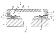
本実施例に係るインクジェットプリントヘッドは、図1〜図3に示すように、インク吐出のための吐出圧発生素子としてヒーター11が設けられた基板10を備えている。ヒーター11の上部には電極12が形成され、上記電極12上には、パッシベーション層13及びアンチキャビテーション層14が形成される。ここで、上部とは、図2もしくは図4において、インクがインクチャンバー21からノズル31に向かって吐出していく方向を指す。また、基板10上には、インクチャンバー21aを限定する流路形成層20が積層され、流路形成層20上には、インク吐出のためのノズル31を形成するノズル層30が積層される。流路形成層20と基板10との間には、流路形成層20を基板10上に安定的に接合させるための接着層15が介在される。温度センシング部43は、パッシベーション層13とアンチキャビテーション層14との間に形成される複数の温度センシング要素を含む。本発明の一実施例においては、温度センシング部43の温度センシング要素がパッシベーション層13とアンチキャビテーション層14との間に形成されているが、ヒーター11の何れの位置にも形成されうることは本発明の技術分野で通常の知識を有する者にとって自明である。
As shown in FIGS. 1 to 3, the ink jet print head according to the present embodiment includes a
温度センシング部43の温度センシング要素は、ヒーター11に対応して形成され、ヒーター11からインクチャンバー21aへの熱経路に設置されるか、インクチャンバー21a、ノズル31及びインク吐出力発生器(例えば、ヒーター11)を有するノズルモジュール内の位置に設置されることで、ノズル21を通してインクチャンバー21aからインクを吐出するために一つ以上のバブルを発生させ、インク吐出力発生器(例えば、ヒーター11)の温度を検出する。ヒーター11に対応して形成されるとは、例えば、ヒーターの位置などに依存して形成されることを指し、その他の要因によって形成されてもよい。
The temperature sensing element of the
インクチャンバーに対応してノズルが形成されている、つまり、ヒーターの熱によってインクがノズルを通してインクチャンバーから吐出されるようになっている。よってヒーターの温度は、ヒーター及び/またはノズルに対応して配置されるインクの温度を表すことができる。ノズルが不良またはミッシングノズルであると、ノズルは、正常的なインク吐出動作で機能せずに詰まるようになる。したがって、他のインクチャンバー内の他のインク及び対応するノズルが正常的なインク吐出動作で機能するので、インクチャンバー内に収容されたインクの温度は、他のインクチャンバー内に収容された他のインクの温度と異なっている。 Nozzles are formed corresponding to the ink chambers, that is, ink is ejected from the ink chambers through the nozzles by the heat of the heater. Therefore, the temperature of the heater can represent the temperature of the ink disposed corresponding to the heater and / or the nozzle. If the nozzle is defective or a missing nozzle, the nozzle becomes clogged without functioning in a normal ink ejection operation. Accordingly, since the other inks in the other ink chambers and the corresponding nozzles function in a normal ink ejection operation, the temperature of the ink contained in the ink chamber is different from the other ink contained in the other ink chamber. It is different from the ink temperature.
基板10としてシリコンウェハーが使用され、基板10には、インク貯蔵部(図示せず)からインクを供給するためのインク供給口10aが形成される。ヒーター11は、基板10の上部に形成される通常の薄膜ヒーターであり、電極12から伝達される電気的信号を熱エネルギーに転換することで、チャンバー21a内部のインクを加熱する。ヒーター11としては、窒化タンタル(TaN)またはアルミニウムタンタル(Ta-Al)などの発熱抵抗物質が使用される。電極12は、アルミニウム(Al)などの優れた導電性を有する金属物質を蒸着することで形成され、蒸着された金属層は、フォトリソグラフィ工程及びエッチング工程によって所定の配線形態でヒーター11の上部に形成される。また、電極12は、通常のCMOSロジック及びパワートランジスタから信号を受けた後、この信号をヒーター11に伝達する。
A silicon wafer is used as the
ヒーター11と基板10との間には、シリコン酸化膜からなる絶縁層として熱貯蔵層16が設けられる。熱貯蔵層16は、ヒーター11から発生した熱が基板10に漏れる(伝達される)ことを防止する機能をする。
A
パッシベーション層13は、ヒーター11及び電極12の酸化またはヒーター11及び電極12とインクとの直接的な接触を防止することで、ヒーター11及び電極12を保護する。パッシベーション層13は、良好な絶縁性及び熱伝逹効率を有するシリコン窒化膜(SiN)として形成される。パッシベーション層13上で各ノズル31に対応するヒーター11の発熱領域上には、アンチキャビテーション層14が形成される。
The
アンチキャビテーション層14は、チャンバー21a内部の気泡が収縮及び消滅するときに生じるキャビテーション圧力(Cavitation Force)からヒーター11を保護し、インクによって生じるヒーター11の腐食を防止する。アンチキャビテーション層14は、パッシベーション層13の上部に所定厚さのタンタル(Ta)を蒸着することで形成される。
The
このとき、アンチキャビテーション層14は、温度センシング部43の上部の各ノズルに対応する位置にタンタル(Ta)を蒸着及びパターニングすることで形成できるが、図4に示すように、アンチキャビテーション層を省略することも可能である。このようにアンチキャビテーション層を省略するとしても、パッシベーション13の上部に設けられた温度センシング部43は、ヒーター11の温度を感知する機能だけでなく、チャンバー21a内部の気泡が収縮して消滅するときに生じるキャビテーション圧力(Cavitation Force)からヒーター11を保護するキャビテーション防止機能を付加的に行う。このとき、温度センシング部43は、ヒーター11の発熱部に対応する広さを有している。したがって、変形された実施例では、タンタル(Ta)を蒸着及びパターニングすることでアンチキャビテーション層を形成する工程が省略されるので、工程効率化を図ることができる。
At this time, the
流路形成層20は、インク供給口10aとノズル31とを連結するインク流路21を定義し、各インク流路21は、インクが充填されるチャンバー21aと、インク供給口10aとチャンバー21aとを連結し、インク供給口10aとチャンバー21aとの間のインクの流路を制限するリストリクター21bとを含んで構成される。
The flow
パッシベーション層13とアンチキャビテーション14との間には、ヒーター11の温度を感知するための温度センシング部43を形成する温度センシング要素として、第1温度センシング要素としての第1金属層41及び第2温度センシング要素としての第2金属層42が設けられる。
Between the
温度センシング部43の温度センシング要素は、薄膜熱電対として設けられるが、温度を感知するための温度センサーとしては、TCR(temperature coefficient of resistance)を用いた温度センサーを使用することもできる。しかし、TCRを用いた温度センサーは、金属の抵抗変化値を用いて温度を測定するので、比較的広い領域の平均温度を測定するだけで、特定ポイントまたは位置の温度を測定することは不可能である。したがって、本発明では、熱電対を用いた温度センシング部43を備えることが好ましい。
Although the temperature sensing element of the
熱電対は、二種類の異なる金属で輪状の閉回路を構成した後、閉回路の二種類の金属が接触して形成された二つの接点のうち一側の接点を高温に連結し、他側の接点を低温に連結することで、閉回路を構成する金属の種類及び二つの接点の温度差によって起電力が発生するゼーベック効果(Seebeck Effect)を用いた温度センサーである。ここで、ゼーベック効果は、温度を表すために温度差を電力に変換することである。 The thermocouple is composed of two different types of metals to form a ring-shaped closed circuit, and then one of the two contacts formed by the contact of the two types of closed circuit metal is connected to a high temperature, and the other side This is a temperature sensor using the Seebeck Effect in which an electromotive force is generated due to the kind of metal constituting the closed circuit and the temperature difference between the two contacts. Here, the Seebeck effect is to convert a temperature difference into electric power in order to represent temperature.
したがって、熱電対は、上記二種類の金属が接触して形成された一側の接点を、温度を測定しようとする領域に直接接続し、二種類の金属が接触しない状態で開放された他側端をデータ取得ボード(Data Acquisition Board)に連結することで、温度信号を容易に得ることができる。熱電対は、このような温度信号を用いて測定領域の温度を簡便に測定することができ、熱電対を構成する二種類の金属の種類によって多様な型に分類される。 Therefore, the thermocouple connects the contact on one side formed by the contact of the two types of metal directly to the region where the temperature is to be measured, and the other side opened without the contact of the two types of metal. A temperature signal can be easily obtained by connecting the end to a data acquisition board. Thermocouples can easily measure the temperature of the measurement region using such a temperature signal, and are classified into various types according to the types of two types of metals constituting the thermocouple.
本発明の好適な一実施例では、クロメル及びアルメルを用いたk型熱電対を使用する。 In a preferred embodiment of the present invention, a k-type thermocouple using chromel and alumel is used.
したがって、本発明は、クロメル及びアルメルを含むk型熱電対を使用することで、ヒーター11の温度を容易に測定するために、第1金属層41の一端部と第2金属層42の一端部をパッシベーション層13の上部に接合し、温度センシング部43の第1温度センシング要素として第1金属層41を形成し、第2温度センシング要素として第2金属層42を形成した。
一つの形態として、第1金属層41がノズルモジュールのヒーターの位置に対応して、つまりヒーターの位置に依存して配置される。そして第2金属層42が、各ヒーターに沿って配置されて、第1金属層に連結されるように形成されるが、当該形態に限定されるものではない。
Therefore, the present invention uses one end of the
As one form, the
形成状態についてより詳細に説明すると、第1金属層41は、クロメルをスパッタリングまたは化学気相蒸着法によって蒸着した後、これをパターニングすることで形成され、第2金属層42は、アルメルをスパッタリングまたは化学気相蒸着法によって蒸着した後、これをパターニングすることで形成される。
The
温度センシング部43でヒーター11の発熱温度を測定し、測定された温度のアナログ信号をA/Dコンバーター(図示せず)を通してデジタル信号に変換した後、このデジタル信号を後述する制御部50に伝送する。
The
図5は、本発明の一実施例に係るインクジェットプリントヘッドを有する画像形成装置を示した制御ブロック図で、本発明に係る画像形成装置は、制御部50及びヒーター駆動部51を含んで構成される。
FIG. 5 is a control block diagram illustrating an image forming apparatus having an inkjet print head according to an embodiment of the present invention. The image forming apparatus according to the present invention includes a
図1〜図5に示すように、制御部50は、印刷動作の入力信号によってヒーター駆動部51を通してヒーター11を駆動し、インク吐出力を用いてインクを吐出することで、印刷媒体上に画像を形成する。
As shown in FIGS. 1 to 5, the
流路形成層20によって区画されるチャンバー21aと、チャンバー21aの下部に設けられたヒーター11と、ヒーター11の温度を測定する温度センシング部43と、チャンバー21aの上部に設けられたノズル31とを含む単位ノズルモジュールは、インクジェットプリントヘッドに複数個で形成される。
A
上記のようなノズルモジュールにおいては、ヒーター11の駆動によってチャンバー21a内のインクにバブルが発生し、そのバブルの膨張力(インク吐出力)によってインク液滴がノズル31を通して吐出される。
In the nozzle module as described above, bubbles are generated in the ink in the
このとき、温度センシング部43は、ヒーター11駆動時のヒーター11の温度を持続的に感知し、温度センシング部43によって感知された温度信号は、制御部50に伝送される。
At this time, the
ヒーター11から受けた熱が温度センシング部43に伝達されるように、第2金属層42及び第1金属層41の各端部は、温度センシング部43の各端子に連結される。そして、温度センシング部43によって検出された温度を表す電圧信号は、制御部50に出力される。したがって、温度センシング部43の各端子は、第2金属層42の一つの先端及び第1金属層41の各先端に連結され、温度センシング部43は、第2金属層42及び第1金属層41の各端部によって形成された各接点の熱を用いて温度を測定する。さらに、温度センシング部43は、第1金属層及び第2金属層が前記ヒーターに対応して配置されているので、測定された温度及び第2金属層42と第1金属層41との接点によってヒーターの位置を検出する。ここで対応して配置されているとは、例えば第1金属層と第2金属層の接点の下部の位置にヒーターが存在していることをいう。
Each end of the
例えば、一つのノズル31がミッシングノズル(不良ノズル)であるとき、対応するインクチャンバー21aと対応するヒーター11との間に接点が配置されるので、第1金属層41及び第2金属層42によって形成された一つの接点は、他の接点と異なる温度を示している。温度センシング部43によって検出された一つの接点の温度を表す電圧信号は、他の接点の他の温度を表す他の電圧信号と異なっている。電圧と他の電圧との間の差によって、制御部50は、対応するノズルをミッシングノズルであると判断し、ミッシングノズルの位置を判断することができる。
インクジェットヘッドが複数列のノズルを含むとき、複数の第2金属層42は、ノズルの各列に対応するヒーターに沿って配置され、各温度センシング部43に連結される。ここで、一つの温度センシング部は、複数の第2金属層42に連結されるのに使用される。制御部50は、各第1金属層及び複数の各第2金属層42を用いて各ヒーターの温度を表すための電圧を検出する。
For example, when one
When the inkjet head includes a plurality of rows of nozzles, the plurality of second metal layers 42 are disposed along heaters corresponding to the rows of nozzles and connected to the
正常な状態で制御部50の信号によってヒーター11が発熱する場合、チャンバー21a内の加熱したインクがノズル31を通して吐出されるので、ヒーター11が所定の温度帯域に維持される。すなわち、インクが正常的にノズル31を通して吐出される場合、ヒーター11は、インクにバブルが発生する温度である約298℃±30℃の範囲に維持される。
When the
ノズル31が詰まった状態でヒーター11が加熱する場合、チャンバー21a内のインクがノズル31を通して吐出されないので、ヒーター11の温度は、持続的に増加して330℃を越えるようになる。
When the
また、ヒーター11に異常が発生し、ヒーター11が発熱しない場合、ヒーター11は常温に維持される。
Further, when an abnormality occurs in the
したがって、ノズル31が詰まったり、ヒーター11が発熱しないミッシングノズルが発生する場合、ヒーター11の温度は、上記所定の温度帯域(例えば、298℃±30℃)から逸脱する。そのため、制御部50は、ヒーター11の温度を持続的にモニタリングし、ヒーター11の温度が上記所定の温度帯域から逸脱したと判断される場合、該当のノズルモジュールのノズル31をミッシングノズルであると判断する。
Therefore, when the
ミッシングノズル判断の誤差を減少するために、制御部は、測定されたヒーター11の温度が100℃以下である場合、ヒーターが発熱していないと判断し、測定されたヒーター11の温度が330℃を超える場合、ノズル31が詰まっていると判断する。すなわち、所定の温度帯域の幅を100℃〜330℃に広くし、ヒーター11の温度が所定の温度帯域から逸脱すると、該当のノズルモジュールのノズル31をミッシングノズルであると判断する。
In order to reduce the error in determining the missing nozzle, the control unit determines that the heater is not generating heat when the measured temperature of the
図6は、本発明の一実施例に係る図5の画像形成装置の制御部及び温度センシング部を示したブロック図である。図1、図5及び図6に示すように、温度センシング部43は、第2金属層42と各第1金属層41との接点の温度を表す電圧を検出するセンサー部44を含む。センサー部44は、第2金属層42と各第1金属層41に対応する複数のセンサーを含み、各熱によって第2金属層42と各第1金属層41との接点の各温度を表す信号を発生する。制御部50は、センサー部44に連結され、発生した信号を受信する。
6 is a block diagram illustrating a control unit and a temperature sensing unit of the image forming apparatus of FIG. 5 according to an embodiment of the present invention. As shown in FIGS. 1, 5, and 6, the
ミッシングノズルを検出した後、多様なミッシングノズル補正方法を通して印刷品質の低下を防止する。ミッシングノズル補正方法の一例は、大韓民国公開特許公報第10-2006-67056号に開示されている。多様な従来のミッシングノズル補償方法が本発明に適用可能であるので、それに対する説明は省略する。 After detecting the missing nozzle, the printing quality is prevented from being deteriorated through various missing nozzle correction methods. An example of a missing nozzle correction method is disclosed in Korean Patent Publication No. 10-2006-67056. Since various conventional missing nozzle compensation methods can be applied to the present invention, a description thereof will be omitted.
例えば、他のノズルは、ミッシングノズルがインクを吐出して画像を形成するようになっている印刷媒体の一部分上にインクを吐出するのに使用される。したがって、ミッシングノズルからインクが吐出されない印刷媒体の部分が、他のノズルを使用することで補償される。従来の維持動作は、ミッシングノズル補償方法として使用可能である。 For example, other nozzles are used to eject ink onto a portion of a print medium in which a missing nozzle is adapted to eject ink to form an image. Therefore, the portion of the print medium where ink is not ejected from the missing nozzle is compensated by using other nozzles. The conventional maintenance operation can be used as a missing nozzle compensation method.
上記のような検出過程を通して、印刷動作時ごとにミッシングノズルを検出するので、従来のスキャニングを用いたミッシングノズル検出方法に比べて迅速にミッシングノズルを発見することができ、高解像度のスキャニングセンサーなしにもミッシングノズルを正確に検出することができる。
また、印刷及びスキャニングなどの一連の複雑な過程を省略することで、不必要な印刷を防止できるので、印刷媒体やインクの浪費を予防することができる。
Through the detection process as described above, the missing nozzle is detected at every printing operation. Therefore, the missing nozzle can be found quickly compared to the conventional missing nozzle detection method using scanning, and there is no high-resolution scanning sensor. In addition, the missing nozzle can be accurately detected.
Further, unnecessary printing can be prevented by omitting a series of complicated processes such as printing and scanning, so that waste of printing media and ink can be prevented.
以上説明した本発明に係るミッシングノズル検出方法及びこれを用いたインクジェットプリントヘッドは、本発明を実施するための一つの実施例に過ぎない。したがって、本発明は、上述した実施例に限定されるものでなく、本発明の技術的思想内で当該分野で通常の知識を有する者によって多様に変形可能であろう。 The missing nozzle detection method according to the present invention described above and the ink jet print head using the same are only one embodiment for carrying out the present invention. Therefore, the present invention is not limited to the above-described embodiments, and can be variously modified by those having ordinary knowledge in the art within the technical idea of the present invention.
以上、添付図面を参照しながら本発明の好適な実施形態について詳細に説明したが、本発明はかかる例に限定されない。本発明の属する技術の分野における通常の知識を有する者であれば、特許請求の範囲に記載された技術的思想の範疇内において、各種の変更例または修正例に想到し得ることは明らかであり、これらについても、当然に本発明の技術的範囲に属するものと了解される。 The preferred embodiments of the present invention have been described in detail above with reference to the accompanying drawings, but the present invention is not limited to such examples. It is obvious that a person having ordinary knowledge in the technical field to which the present invention pertains can come up with various changes or modifications within the scope of the technical idea described in the claims. Of course, it is understood that these also belong to the technical scope of the present invention.
10 基板
11 ヒーター
12 電極
13 パッシベーション層
14 アンチキャビテーション層
20 流路形成層
21a チャンバー
30 ノズル層
31 ノズル
41,42 第1及び第2金属層
43 温度センシング部
50 制御部
DESCRIPTION OF
Claims (22)
前記チャンバー内のインクを加熱するための複数のヒーターと、
前記ヒーターに対応する複数のノズルと、
を備える画像形成装置のインクジェットヘッドに使用されるミッシングノズル検出方法であって、
前記各ヒーターの温度感知段階と;
感知された温度が所定の温度帯域から逸脱する場合、前記ヒーターに対応する前記ノズルをミッシングノズルであると判断する段階と;
を含むことを特徴とする、ミッシングノズル検出方法。 A plurality of chambers filled with ink;
A plurality of heaters for heating the ink in the chamber;
A plurality of nozzles corresponding to the heater;
A missing nozzle detection method used for an inkjet head of an image forming apparatus comprising:
A temperature sensing step for each of the heaters;
Determining that the nozzle corresponding to the heater is a missing nozzle if the sensed temperature deviates from a predetermined temperature band;
A missing nozzle detection method comprising:
前記各ノズルモジュールに設けられ、前記ヒーターの発熱温度を感知する一つ以上の温度センシング部と、
前記一つ以上の温度センシング部によって感知された温度が所定の温度帯域から逸脱する場合、前記ノズルモジュールの前記ノズルをミッシングノズルであると判断する制御部と、
を備えることを特徴とする、画像形成装置。 A plurality of nozzle modules including a chamber filled with ink, a nozzle corresponding to the chamber, and a heater for heating the ink in the chamber;
One or more temperature sensing units provided in each nozzle module for sensing the heat generation temperature of the heater;
A controller that determines that the nozzle of the nozzle module is a missing nozzle when a temperature sensed by the one or more temperature sensing units deviates from a predetermined temperature band;
An image forming apparatus comprising:
前記一つ以上の温度センシング部は、前記ヒーターに対応して前記パッシベーション層の上部に形成されることを特徴とする、請求項5に記載の画像形成装置。 A passivation layer for protecting the heater;
The image forming apparatus according to claim 5, wherein the one or more temperature sensing units are formed on the passivation layer corresponding to the heater.
前記ヒーターに対応するチャンバー及び前記チャンバーに連結される流路を形成する流路形成層と、
前記チャンバーに対応するノズルが形成されたノズル層と、
前記ノズルに対応するパッシベーション層の上部に接合され、一つ以上の温度センシング部を形成する第1金属層及び第2金属層と、
前記一つ以上の温度センシング部によって感知された温度が所定の温度帯域から逸脱する場合、前記ノズルをミッシングノズルであると判断する制御部と、
を含むことを特徴とする、画像形成装置。 A substrate on which a heater and a passivation layer protecting the heater are formed;
A flow path forming layer that forms a chamber corresponding to the heater and a flow path connected to the chamber;
A nozzle layer in which nozzles corresponding to the chamber are formed;
A first metal layer and a second metal layer bonded to an upper portion of the passivation layer corresponding to the nozzle and forming one or more temperature sensing units;
A control unit that determines that the nozzle is a missing nozzle when the temperature sensed by the one or more temperature sensing units deviates from a predetermined temperature band;
An image forming apparatus comprising:
前記各ノズルモジュールに設けられ、前記各モジュールの前記ヒーターの発熱温度を検出するする温度センシング部と、
を含むことを特徴とする、インクジェットプリントヘッド。 A plurality of nozzle modules including a chamber filled with ink, a nozzle corresponding to the chamber, and a heater for heating the ink in the chamber;
A temperature sensing unit that is provided in each nozzle module and detects a heat generation temperature of the heater of each module;
An ink jet print head comprising:
前記各ノズルモジュールに設けられ、前記各モジュールの前記ヒーターの発熱温度を検出するする温度センシング部と、
を含むことを特徴とする、画像形成装置。 A plurality of nozzle modules including a chamber filled with ink, a nozzle corresponding to the chamber, and a heater for heating the ink in the chamber;
A temperature sensing unit that is provided in each nozzle module and detects a heat generation temperature of the heater of each module;
An image forming apparatus comprising:
を含み、
前記発熱温度は、前記第1温度センシング要素と前記第2温度センシング要素との間に形成された位置に対応する複数の温度を含むことを特徴とする、請求項12に記載の画像形成装置。 The temperature sensing unit includes a first temperature sensing element disposed corresponding to the position of the heater of the nozzle module, and a second temperature sensing element disposed along each of the heaters and connected to the position of the first temperature sensing element. A temperature sensing element;
Including
The image forming apparatus according to claim 12, wherein the heat generation temperature includes a plurality of temperatures corresponding to positions formed between the first temperature sensing element and the second temperature sensing element.
前記第1温度センシング要素及び前記第2温度センシング要素に連結されたセンサー部と、を含み、
前記第1温度センシング要素及び前記第2温度センシング要素は、熱を伝達して、
前記センサー部は前記熱によって、前記対応するヒーターの温度を測定することを特徴とする、請求項12に記載の画像形成装置。 The temperature sensing unit includes a first temperature sensing element and a second temperature sensing element formed corresponding to the heater of each nozzle module;
A sensor unit coupled to the first temperature sensing element and the second temperature sensing element;
The first temperature sensing element and the second temperature sensing element transfer heat,
The image forming apparatus according to claim 12, wherein the sensor unit measures the temperature of the corresponding heater by the heat.
前記温度センシング部は、前記各ヒーターの前記熱の差によって前記各ヒーターのうち前記ヒーターの前記発熱温度を検出することを特徴とする、請求項12に記載の画像形成装置。 Each of the heaters generates heat transferred to the temperature sensing unit,
The image forming apparatus according to claim 12, wherein the temperature sensing unit detects the heating temperature of the heater among the heaters based on the difference in heat of the heaters.
前記ヒーターに対応するチャンバー及び前記チャンバーに連結される流路を定義する流路形成層と、
前記チャンバーに対応するノズルが形成されたノズル層と、
を含み、
前記温度センシング部は、前記各ノズルに対応する前記パッシベーション層の上部に接合され、温度センシング部を形成する第1金属層及び第2金属層を備えることを特徴とする、請求項12に記載の画像形成装置。 The nozzle module includes a heater and a substrate on which a passivation layer for protecting the heater is formed,
A flow path forming layer defining a chamber corresponding to the heater and a flow path connected to the chamber;
A nozzle layer in which nozzles corresponding to the chamber are formed;
Including
The temperature sensing unit according to claim 12, further comprising a first metal layer and a second metal layer that are joined to an upper part of the passivation layer corresponding to each nozzle and form a temperature sensing unit. Image forming apparatus.
前記インクジェットプリントヘッド及び前記制御部は、一つの結合体に形成されることを特徴とする請求項12に記載の画像形成装置。 When the temperature detected by the temperature sensing unit deviates from a predetermined temperature band, the control unit further determines that one of the nozzles is a missing nozzle,
The image forming apparatus according to claim 12, wherein the ink jet print head and the control unit are formed in one combined body.
The image forming apparatus according to claim 12, wherein the plurality of nozzle modules and the temperature sensing unit are formed as a single body.
Applications Claiming Priority (1)
| Application Number | Priority Date | Filing Date | Title |
|---|---|---|---|
| KR1020070065437A KR20090001217A (en) | 2007-06-29 | 2007-06-29 | Method for detecting missing nozzle and inkjet print head using it |
Publications (1)
| Publication Number | Publication Date |
|---|---|
| JP2009012461A true JP2009012461A (en) | 2009-01-22 |
Family
ID=39720685
Family Applications (1)
| Application Number | Title | Priority Date | Filing Date |
|---|---|---|---|
| JP2008145725A Pending JP2009012461A (en) | 2007-06-29 | 2008-06-03 | Ink jet print head and missing nozzle detection method |
Country Status (5)
| Country | Link |
|---|---|
| US (1) | US20090002425A1 (en) |
| EP (1) | EP2008828A3 (en) |
| JP (1) | JP2009012461A (en) |
| KR (1) | KR20090001217A (en) |
| CN (1) | CN101332700A (en) |
Cited By (2)
| Publication number | Priority date | Publication date | Assignee | Title |
|---|---|---|---|---|
| JP2015214079A (en) * | 2014-05-09 | 2015-12-03 | キヤノン株式会社 | Substrate, liquid discharge head, recording device and determination method of discharge state of liquid |
| JP2019048468A (en) * | 2018-11-21 | 2019-03-28 | ヒューレット−パッカード デベロップメント カンパニー エル.ピー.Hewlett‐Packard Development Company, L.P. | Print head die |
Families Citing this family (10)
| Publication number | Priority date | Publication date | Assignee | Title |
|---|---|---|---|---|
| JP5679825B2 (en) * | 2010-01-21 | 2015-03-04 | キヤノン株式会社 | Liquid discharge apparatus and liquid discharge head abnormality detection method |
| KR102372245B1 (en) * | 2013-11-21 | 2022-03-08 | 젠맵 에이/에스 | Antibody-drug conjugate lyophilised formulation |
| CN105764695B (en) * | 2013-11-26 | 2018-08-07 | 惠普发展公司,有限责任合伙企业 | Fluid ejection apparatus with unilateral heat sensor |
| US9162509B1 (en) * | 2014-03-31 | 2015-10-20 | Xerox Corporation | System for detecting inoperative inkjets in printheads ejecting clear ink using thermal substrates |
| CN107206793B (en) * | 2015-04-10 | 2018-12-04 | 惠普发展公司,有限责任合伙企业 | The tilting section of metallic conductor is removed when forming print head |
| ITUB20153006A1 (en) * | 2015-08-07 | 2017-02-07 | System Spa | Control method for detecting the operating status of the nozzles of an ink jet printhead. |
| WO2017131614A1 (en) * | 2016-01-25 | 2017-08-03 | Hewlett-Packard Development Company, L.P. | Fluid device |
| IT201600083000A1 (en) * | 2016-08-05 | 2018-02-05 | St Microelectronics Srl | MICROFLUID DEVICE FOR THE THERMAL SPRAYING OF A LIQUID CONTAINING PIGMENTS AND / OR AROMAS WITH AN AGGREGATION OR DEPOSIT TREND |
| WO2021154245A1 (en) * | 2020-01-29 | 2021-08-05 | Hewlett-Packard Development Company, L.P. | Fluidic dies with thermal sensors on membrane |
| JP2022113266A (en) * | 2021-01-25 | 2022-08-04 | セイコーエプソン株式会社 | Liquid jet head and liquid jet device |
Family Cites Families (8)
| Publication number | Priority date | Publication date | Assignee | Title |
|---|---|---|---|---|
| JP3363524B2 (en) * | 1993-06-30 | 2003-01-08 | キヤノン株式会社 | Printhead, heater board thereof, printing apparatus and method |
| TW479022B (en) * | 2000-08-29 | 2002-03-11 | Acer Peripherals Inc | Drive circuit of ink-jet head with temperature detection function |
| US6460964B2 (en) * | 2000-11-29 | 2002-10-08 | Hewlett-Packard Company | Thermal monitoring system for determining nozzle health |
| US7232079B2 (en) * | 2003-09-12 | 2007-06-19 | Hewlett-Packard Development Company, L.P. | Determining whether thermal fluid-ejection nozzle ejected fluid upon firing based on temperature and/or resistance |
| KR100636325B1 (en) | 2004-12-14 | 2006-10-18 | 삼성전자주식회사 | method for compensating missing nozzle of printer and printer using it |
| KR100636236B1 (en) | 2005-05-24 | 2006-10-19 | 삼성전자주식회사 | Method and apparatus for detecting missing nozzle |
| KR100850711B1 (en) * | 2005-06-17 | 2008-08-06 | 삼성전자주식회사 | Method and apparatus for controlling temperature of printer head chip |
| JP4953703B2 (en) * | 2006-06-19 | 2012-06-13 | キヤノン株式会社 | Recording apparatus and ink discharge defect detection method |
-
2007
- 2007-06-29 KR KR1020070065437A patent/KR20090001217A/en not_active Application Discontinuation
-
2008
- 2008-04-22 US US12/107,174 patent/US20090002425A1/en not_active Abandoned
- 2008-05-09 CN CNA200810127775XA patent/CN101332700A/en active Pending
- 2008-05-29 EP EP08157230A patent/EP2008828A3/en not_active Withdrawn
- 2008-06-03 JP JP2008145725A patent/JP2009012461A/en active Pending
Cited By (2)
| Publication number | Priority date | Publication date | Assignee | Title |
|---|---|---|---|---|
| JP2015214079A (en) * | 2014-05-09 | 2015-12-03 | キヤノン株式会社 | Substrate, liquid discharge head, recording device and determination method of discharge state of liquid |
| JP2019048468A (en) * | 2018-11-21 | 2019-03-28 | ヒューレット−パッカード デベロップメント カンパニー エル.ピー.Hewlett‐Packard Development Company, L.P. | Print head die |
Also Published As
| Publication number | Publication date |
|---|---|
| CN101332700A (en) | 2008-12-31 |
| EP2008828A3 (en) | 2009-08-05 |
| US20090002425A1 (en) | 2009-01-01 |
| KR20090001217A (en) | 2009-01-08 |
| EP2008828A2 (en) | 2008-12-31 |
Similar Documents
| Publication | Publication Date | Title |
|---|---|---|
| JP2009012461A (en) | Ink jet print head and missing nozzle detection method | |
| JP2009040035A (en) | Ink-jet image forming apparatus and its control method | |
| JP2009012458A (en) | Image forming apparatus, missing nozzle detection method and ink jet print head employing it | |
| US9033442B2 (en) | Printing apparatus and discharge inspection method | |
| US20090058914A1 (en) | Inkjet print head and method thereof | |
| US7806503B2 (en) | Printing apparatus and ink discharge failure detection method | |
| JP4827625B2 (en) | Recording head ejection inspection method and recording apparatus | |
| US20060284915A1 (en) | Method and apparatus to control a temperature of a printer head chip | |
| US8186798B2 (en) | Ink jet recording apparatus that measures change in temperature after heater is driven and determines discharge state and method for determining discharge state | |
| US20140300657A1 (en) | Printing apparatus and ink discharge state determination method | |
| JP6150519B2 (en) | INKJET RECORDING HEAD SUBSTRATE, INKJET RECORDING HEAD, INKJET RECORDING HEAD MANUFACTURING METHOD, INKJET RECORDING DEVICE, AND INKJET RECORDING HEAD SUBSTRATE | |
| JP5404022B2 (en) | Discharge state judgment method | |
| JP2009012456A (en) | Missing nozzle detection method and ink jet print head employing it | |
| US7862157B2 (en) | Ink jet recording head | |
| JP2009083227A (en) | Inkjet recording head and inkjet recorder with head | |
| US9597871B2 (en) | Base, liquid discharge head, printing apparatus, and method for determining liquid discharge status | |
| JP2003145770A (en) | Substrate for recording head, recording head, recorder and method for manufacturing recording head | |
| JP2011168046A (en) | Inkjet recording device and abnormality detecting method of inkjet recording head | |
| EP3368320B1 (en) | Fluid printhead and method of controlling operation of plurality of drive elements of printhead | |
| JP2008149573A (en) | Ink-jet recording head and ink-jet recording device | |
| US20210016570A1 (en) | Element substrate, liquid discharge head, and printing apparatus | |
| JP2001129995A (en) | Ink-jet recording head | |
| JP2008230204A (en) | Recording apparatus and its ink discharge state determination method |
Legal Events
| Date | Code | Title | Description |
|---|---|---|---|
| RD02 | Notification of acceptance of power of attorney |
Free format text: JAPANESE INTERMEDIATE CODE: A7422 Effective date: 20090515 |
|
| RD04 | Notification of resignation of power of attorney |
Free format text: JAPANESE INTERMEDIATE CODE: A7424 Effective date: 20090706 |
|
| RD04 | Notification of resignation of power of attorney |
Free format text: JAPANESE INTERMEDIATE CODE: A7424 Effective date: 20090707 |