JP2009010977A - Wireless terminal device - Google Patents
Wireless terminal device Download PDFInfo
- Publication number
- JP2009010977A JP2009010977A JP2008208440A JP2008208440A JP2009010977A JP 2009010977 A JP2009010977 A JP 2009010977A JP 2008208440 A JP2008208440 A JP 2008208440A JP 2008208440 A JP2008208440 A JP 2008208440A JP 2009010977 A JP2009010977 A JP 2009010977A
- Authority
- JP
- Japan
- Prior art keywords
- data
- wireless
- unit
- wireless terminal
- relay
- Prior art date
- Legal status (The legal status is an assumption and is not a legal conclusion. Google has not performed a legal analysis and makes no representation as to the accuracy of the status listed.)
- Granted
Links
Images


Landscapes
- Mobile Radio Communication Systems (AREA)
Abstract
Description
本発明は、無線端末装置に関し、特に複数の無線端末装置から所望のデータを無線回線を介して無線基地局へ収集する無線通信システムで用いられる無線端末装置に関するものである。 The present invention relates to a wireless terminal device, and more particularly to a wireless terminal device used in a wireless communication system that collects desired data from a plurality of wireless terminal devices to a wireless base station via a wireless line.
特定小電力無線、ブルーツース、コードレス無線、無線LANなどの無線方式に基づき、無線回線を介して無線基地局と接続された複数の無線端末装置からなる無線通信システムとして、各無線端末装置で取得されたデータを1つの通信基地局へ収集するシステムがある(例えば、特許文献1など参照)。 Acquired by each wireless terminal device as a wireless communication system consisting of a plurality of wireless terminal devices connected to a wireless base station via a wireless line based on wireless systems such as specified low power wireless, Bluetooth, cordless wireless, and wireless LAN. There is a system that collects collected data in one communication base station (see, for example, Patent Document 1).
このような無線通信システムでは、本来、通信回線を介して、直接、データ通信可能な無線端末装置間で、通信信号の減衰やノイズ干渉により装置間における通信接続が不可能となる場合がある。例えば、既存の無線通信システムのうち比較的遠い場所に新たな無線端末装置を増設したり、既設の無線端末装置の通信環境が悪化した場合には、無線接続が不可能となる。
従来、このような場合には、既設の無線基地局と無線接続が不可能となった無線端末装置が通信可能な新たな無線基地局を設け、新たな無線基地局でこれら無線基地局から所望のデータを収集するものとなっていた。
In such a wireless communication system, there may be a case where communication connection between devices may be impossible due to attenuation of communication signals or noise interference between wireless terminal devices that are capable of data communication directly via a communication line. For example, when a new wireless terminal device is added to a relatively distant place in the existing wireless communication system or the communication environment of the existing wireless terminal device deteriorates, wireless connection becomes impossible.
Conventionally, in such a case, a new wireless base station capable of communicating with a wireless terminal device that cannot be wirelessly connected to an existing wireless base station is provided, and a new wireless base station can request from these wireless base stations. It was intended to collect data.
しかしながら、このような従来の無線通信システムでは、システム規模を拡張して無線接続が不可能となった無線端末装置からデータを収集するため新たな無線基地局を別途設ける必要があり、システム全体として大幅なコストアップとなるという問題点があった。特に、無線基地局で収集したデータを公衆通信網を介して遠隔地にあるセンタ装置で収集して利用する場合、無線基地局自体の設備コストだけでなく公衆通信網の回線利用コストも増加するという問題もあった。
本発明はこのような課題を解決するためのものであり、大幅なコストアップを必要とすることなく無線通信システムの規模を拡張できる無線端末装置を提供することを目的としている。
However, in such a conventional wireless communication system, it is necessary to separately provide a new wireless base station in order to collect data from wireless terminal devices whose wireless connection is impossible due to the expansion of the system scale. There was a problem that the cost was significantly increased. In particular, when data collected by a radio base station is collected and used by a remote center device via a public communication network, not only the equipment cost of the radio base station itself but also the line use cost of the public communication network increases. There was also a problem.
The present invention has been made to solve such problems, and an object of the present invention is to provide a wireless terminal device capable of expanding the scale of a wireless communication system without requiring a significant cost increase.
このような目的を達成するために、本発明にかかる無線端末装置は、複数の無線端末装置と無線基地局との間で無線通信を介して各種データをやり取りする無線通信システムで用いられ、これら無線端末装置と無線基地局との間でやり取りされるデータを中継転送する無線端末装置であって、他の無線端末装置および無線基地局と無線通信を行う無線通信手段と、各種データを記憶する記憶手段と、無線通信手段で受信したデータを記憶部に一旦格納するとともに、格納したデータを記憶部から読み出し無線通信手段を介して当該データの送信先へ転送するデータ中継手段と、無線基地局と自装置との間の無線接続可否を確認する接続確認手段とを備え、データ中継手段で、他の無線端末装置から送信されたデータを無線通信手段で監視し、そのデータに中継転送を要求する転送要求情報が含まれている場合には、接続確認手段によりデータの送信先となる無線基地局と自装置との間で無線接続の可能を確認した後、無線通信手段を介して当該他の無線端末装置へ転送許可データを送信し、これに応じて当該他の無線端末装置から送信されたデータの転送を行う。 In order to achieve such an object, a wireless terminal device according to the present invention is used in a wireless communication system that exchanges various data via wireless communication between a plurality of wireless terminal devices and a wireless base station. A wireless terminal device that relays and transfers data exchanged between the wireless terminal device and the wireless base station, stores wireless communication means for performing wireless communication with other wireless terminal devices and wireless base stations, and stores various data A storage unit, a data relay unit that temporarily stores data received by the wireless communication unit in the storage unit, reads the stored data from the storage unit, and transfers the data to a destination of the data via the wireless communication unit, and a wireless base station And a connection confirmation means for confirming whether or not the wireless connection between the wireless communication apparatus and the self-apparatus is possible, the data relay means monitors the data transmitted from other wireless terminal apparatuses by the wireless communication means, If the transfer request information requesting relay transfer is included in the data of the wireless device, after confirming the wireless connection possibility between the wireless base station as the data transmission destination and the own device by the connection confirmation means, The transfer permission data is transmitted to the other wireless terminal device via the communication means, and the data transmitted from the other wireless terminal device is transferred accordingly.
この際、中継対象となる他の無線端末装置に固有のMACアドレスを管理するアドレス管理テーブルをさらに備え、データ中継手段で、接続確認手段により、データの送信先となる無線基地局と自装置との間で無線接続の可能を確認した後、他の無線端末装置のMACアドレスを中継対象としてアドレス管理テーブルへ登録し、無線通信手段で受信した他の無線端末装置から無線基地局へ送信されたデータに付与されている送信元アドレスがアドレス管理テーブルに登録されているMACアドレスのいずれかと一致した場合にのみ、当該データを無線基地局へ転送してもよい。 At this time, an address management table for managing a MAC address unique to another wireless terminal device to be relayed is further provided, and the data relay means, the connection confirmation means, and the wireless base station as the data transmission destination and the own device After confirming that wireless connection is possible, the MAC address of the other wireless terminal device is registered in the address management table as a relay target and transmitted from the other wireless terminal device received by the wireless communication means to the wireless base station. The data may be transferred to the radio base station only when the transmission source address assigned to the data matches one of the MAC addresses registered in the address management table.
本発明によれば、既存の無線基地局と無線接続が不可能となった子機からデータを収集するため新たな無線基地局を別途設ける必要がなくなる。また、無線基地局で収集したデータを公衆通信網を介して遠隔地にあるセンタ装置で収集して利用する場合でも、回線利用コストの増加も回避できる。したがって、大幅なコストアップを必要とすることなく無線通信システムの規模を拡張できる。 According to the present invention, it is not necessary to separately provide a new radio base station in order to collect data from a slave unit that cannot be wirelessly connected to an existing radio base station. Further, even when data collected by a radio base station is collected and used by a center device at a remote location via a public communication network, an increase in line use cost can be avoided. Therefore, the scale of the wireless communication system can be expanded without requiring a significant cost increase.
次に、本発明の実施の形態について図面を参照して説明する。
[第1の実施の形態の構成]
まず、図1を参照して、本発明の一実施の形態にかかる無線端末装置について説明する。図1は本発明の第1の実施の形態にかかる無線端末装置の構成を示すブロック図である。
以下では、本実施の形態にかかる無線端末装置が用いられる無線通信システムとして、複数の無線端末装置(以下、子機という)3A,3B,3Cと1つの無線基地局(以下、親機という)2とが無線回線を介してデータ通信を行うことにより、各子機3A,3B,3Cから親機2が各種データを収集する無線通信システムを例として説明する。
Next, embodiments of the present invention will be described with reference to the drawings.
[Configuration of First Embodiment]
First, a radio terminal apparatus according to an embodiment of the present invention will be described with reference to FIG. FIG. 1 is a block diagram showing a configuration of a wireless terminal apparatus according to the first embodiment of the present invention.
Hereinafter, as a wireless communication system in which the wireless terminal device according to the present embodiment is used, a plurality of wireless terminal devices (hereinafter referred to as slave units) 3A, 3B, 3C and one wireless base station (hereinafter referred to as a base unit) are used. A wireless communication system in which the
この無線端末装置(以下、中継器という)1は、中継対象となる子機3A,3Bおよび親機2の双方と、無線回線を介して通信可能な場所に設置される。この場合、本来、子機3A,3Bは、直接、親機2とデータ通信が可能であるが、親機2と距離が離れているため(通信圏外)無線信号が減衰して、直接、親機2とデータ通信できないものとする。なお、子機3Cは親機2との距離が比較的短く(通信圏内)、直接、親機2とデータ通信できる。
This wireless terminal device (hereinafter referred to as a repeater) 1 is installed in a place where it can communicate with both of the
この中継器1には、制御部11、無線通信インターフェース部(以下、無線通信I/F部という)12、記憶部13、表示部14、および操作入力部15が設けられている。
制御部11は、CPUなどのマイクロプロセッサとその周辺回路からなり、記憶部13やCPU内部に予め格納されているプログラムを実行することにより、各種機能手段を実現する。
The
The
この機能手段として、データ転送手段11Aとアドレス登録手段11Bが設けられている。
データ転送手段11Aは、中継対象となる子機3A,3Bからのデータを無線通信I/F部12で受信した場合、その送信先および送信元を示すMACアドレスを置換して無線通信I/F部12から親機2へ中継転送し、親機2からのデータを無線通信I/F部12で受信した場合、その送信先および送信元を示すMACアドレスを置換して無線通信I/F部12から子機3A,3Bへ中継転送する。
また、アドレス登録手段11Bは、中継対象となる子機3A,3BのMACアドレスの自装置に対する登録処理、および自装置のMACアドレスおよび子機3A,3Bの中継用MACアドレスの親機2に対する登録処理を行う。
As this functional means, a data transfer means 11A and an address registration means 11B are provided.
When the
Further, the address registration means 11B registers the MAC addresses of the
無線通信I/F部12は、特定小電力無線、ブルーツース、コードレス無線、無線LANなどの無線方式に基づき無線信号を送受信することにより、無線回線を介して子機3A,3Bおよび親機2と無線通信を行う回路部である。
記憶部13は、メモリやハードディスクなどの記憶装置からなり、子機3A,3Bの中継に用いるMACアドレスを管理するアドレス管理テーブル13Aのほか、自装置や親機2のMACアドレスなど、制御部11での処理に用いる各種情報を記憶する。メモリとしてCPUの内部メモリを用いてもよい。
表示部14は、LEDなどの表示器からなり、中継器1の動作状態を表示する回路部である。
操作入力部15は、DIPスイッチやキースイッチなどの操作スイッチからなり、各種操作入力を受け付けて制御部11へ出力する回路部である。
The wireless communication I /
The storage unit 13 includes a storage device such as a memory and a hard disk. The
The
The
子機3A,3B,3Cには、それぞれ制御部31、無線通信インターフェース部(以下、無線通信I/F部という)32、記憶部33、およびデータ入出力インターフェース部(以下、入出力I/F部という)34が設けられており、いずれの子機も同様の構成をなしている。
制御部31は、CPUなどのマイクロプロセッサとその周辺回路からなり、記憶部33やCPU内部に予め格納されているプログラムを実行することにより、各種機能手段を実現する。
Each of the
The
この機能手段として、データ送受信手段31Aが設けられている。データ送受信手段31Aは、データ入出力I/F部34で外部の装置(図示せず)から取り込んだデータを、無線通信I/F部32を介して親機2や中継器1へ送信するとともに、無線通信I/F部32を介して親機2や中継器1からのデータを受信する。
無線通信I/F部32は、無線信号を送受信することにより、無線回線を介して親機2や中継器1と無線通信を行う回路部である。
As this functional means, a data transmitting / receiving
The wireless communication I /
記憶部33は、メモリやハードディスクなどの記憶装置からなり、通信相手となる親機2または中継器1のMACアドレス、および自装置のMACアドレスなど、制御部31での処理に用いる各種情報を記憶する。メモリとしてCPUの内部メモリを用いてもよい。
データ入出力I/F部34は、外部の装置と接続して各種データをやり取りする回路部である。
The
The data input / output I /
この無線通信システムでは、データの送信元アドレスおよび送信先アドレスを示す情報として、MACアドレスを付与するものとなっている。図2に子機、親機および中継器の間で送受信されるデータの構成例を示す。このデータには、ヘッダ部40に、送信元装置を示す送信元MACアドレス41、送信先装置を示す送信先MACアドレス42、当該データの信号種別を示す制御コード43などが記載される。また、データ部45には、子機3A〜3Cから親機2へ収集するデータなど各種データが記載される。
In this wireless communication system, a MAC address is assigned as information indicating a data transmission source address and a transmission destination address. FIG. 2 shows a configuration example of data transmitted and received between the slave unit, the master unit, and the repeater. In this data, in the
一般に、MAC(Media Access Control)アドレスは、無線回線(ネットワーク)に接続された各無線端末装置に固有のバイナリ情報であり、このMACアドレスを用いることにより対応する唯一の装置を特定できる。したがって、各装置間でデータ通信を行う場合には、送信元および送信先アドレスとして、それぞれ固有のMACアドレスを用いる必要がある。
各子機3A,3B,3C、親機2、および中継器1は、予め設定された自装置および通信相手のMACアドレスをデータに付与して送信する。また受信したデータのうち、送信先アドレスに自装置のMACアドレスが記載されている場合にのみ、そのデータが自装置宛のものと判断し、そのデータを取得して所定の処理を行うものとなっている。
In general, a MAC (Media Access Control) address is binary information unique to each wireless terminal device connected to a wireless line (network), and by using this MAC address, a corresponding device can be specified. Therefore, when performing data communication between devices, it is necessary to use unique MAC addresses as the source and destination addresses.
Each of the
[データ転送処理]
次に、図3を参照して、中継器1のデータ転送手段11Aにおけるデータ転送処理について説明する。図3は、中継器1のデータ転送手段11Aにおけるデータ転送処理を示すフローチャートである。
データ転送手段11Aでは、無線通信I/F部12を介してデータの受信を開始した場合、図3のデータ転送処理を実行する。
まず、受信したデータが子機から送信されたものかどうか判断する(ステップ100)。ここでは、その受信データのヘッダ部の送信元アドレスを検査してそのMACアドレスが子機で使用されるものかどうか判断してもよく、あるいは制御コードを検査して子機から送信されたものかどうか判断するようにしてもよい。
[Data transfer processing]
Next, a data transfer process in the
When the
First, it is determined whether or not the received data is transmitted from the slave unit (step 100). Here, the transmission source address in the header part of the received data may be inspected to determine whether the MAC address is used by the slave unit, or the control code may be inspected and transmitted from the slave unit. It may be determined whether or not.
ここで、受信データが子機から送信されたものであった場合は(ステップ100:YES)、当該受信データの送信元アドレスを取得し(ステップ101)、それ以外の場合は(ステップ100:NO)、子機宛のデータと判断して当該受信データの送信先アドレスを取得することにより、当該データに関係する子機のMACアドレスを取得する。
そして、記憶部13のアドレス管理テーブル13Aを参照して、当該子機のMACアドレスが、自装置の中継対象となる子機のアドレスかどうか判断し(ステップ103)、中継対象以外の子機アドレスであった場合は(ステップ103:NO)、一連のデータ転送処理を終了して、受信データを破棄する。
If the received data is transmitted from the slave unit (step 100: YES), the source address of the received data is acquired (step 101), otherwise (step 100: NO) ), The MAC address of the slave unit related to the data is acquired by determining the data addressed to the slave unit and acquiring the transmission destination address of the received data.
Then, referring to the address management table 13A of the storage unit 13, it is determined whether or not the MAC address of the child device is an address of a child device to be relayed by the own device (step 103). If it is (step 103: NO), the series of data transfer processing is terminated and the received data is discarded.
一方、当該子機アドレスが中継対象子機のものであった場合は(ステップ103:YES)、そのデータの残りを順次受信し、記憶部13へ一旦格納する(ステップ104)。
そして、当該データを受信完了した後、記憶部13から当該データを読み出し(ステップ105)、アドレス管理テーブル13Aを参照して、当該データの送信先アドレスおよび送信元アドレスを置換し(ステップ106)、無線通信I/F部12から送信して(ステップ107)、一連のデータ転送処理を終了する。
On the other hand, if the slave unit address is that of the relay target slave unit (step 103: YES), the rest of the data is sequentially received and temporarily stored in the storage unit 13 (step 104).
After receiving the data, read the data from the storage unit 13 (step 105), refer to the address management table 13A, replace the transmission destination address and the transmission source address of the data (step 106), Transmission is performed from the wireless communication I / F unit 12 (step 107), and a series of data transfer processing is completed.
このように、本実施の形態では、中継対象となる無線端末装置(子機)と無線基地局(親機)との間に中継用の無線端末装置(中継器)を設け、データ転送手段で、無線端末装置または無線基地局から送信されたデータを受信し記憶部に一旦格納するとともに、格納したデータを記憶部から読み出して無線基地局または無線端末装置へ転送するようにしたので、既存の無線基地局と無線接続が不可能となった子機からデータを収集するため新たな無線基地局を別途設ける必要がなくなる。また、無線基地局で収集したデータを公衆通信網を介して遠隔地にあるセンタ装置で収集して利用する場合でも、回線利用コストの増加も回避できる。したがって、大幅なコストアップを必要とすることなく無線通信システムの規模を拡張できる。 As described above, in this embodiment, a wireless terminal device (relay device) for relay is provided between a wireless terminal device (child device) to be relayed and a wireless base station (parent device), and the data transfer means Since the data transmitted from the wireless terminal device or the wireless base station is received and temporarily stored in the storage unit, the stored data is read from the storage unit and transferred to the wireless base station or the wireless terminal device. It is not necessary to provide a new radio base station separately in order to collect data from the slave units that are no longer wirelessly connected to the radio base station. Further, even when data collected by a radio base station is collected and used by a center device at a remote location via a public communication network, an increase in line use cost can be avoided. Therefore, the scale of the wireless communication system can be expanded without requiring a significant cost increase.
[MACアドレスの置換]
本実施の形態では、中継器1のデータ転送手段11Aにおいて、子機3A,3Bを中継する場合、これら子機3A,3Bごとに中継用MACアドレスを設けてアドレス管理テーブル13Aで管理し、子機3A,3Bから受信したデータについては、その送信先アドレスを親機2のMACアドレスに置換するとともに、その送信元アドレスを中継用MACアドレスに置換して親機2へ送信する。また、親機2から受信したデータについては、その送信先アドレスとして記載されている中継用MACアドレスに対応する子機のMACアドレスに置換するとともに、その送信元アドレスを中継器1のMACアドレスに置換して、子機3Aまたは子機3Bへ送信するようにしている。
これにより、子機3A,3Bに個別の中継用MACアドレスに基づき、親機2では、そのデータの本来の送信元子機を識別でき、中継器1では、そのデータの本来の送信先子機を識別できる。
[Replace MAC address]
In this embodiment, when relaying the
Thereby, based on the individual relay MAC addresses for the
したがって、子機3A,3Bについては、通信相手として中継器1のMACアドレスを設定し、親機2については、通信相手として中継器1のMACアドレスおよび中継用MACアドレスを設定しておくだけで、子機3A,3Bから送信されたデータが中継器1により親機2へ中継転送されるとともに、親機2から送信されたデータが中継器1により子機3A,3Bへ中継転送される。なお、子機3Cには、従来と同様に、通信相手として親機2のMACアドレスを設定しておけばよい。
Therefore, for the
また、本実施の形態では、図4に示すように、アドレス管理テーブル13Aで、中継対象となる子機3A,3BのMACアドレスを、各子機に固有の管理番号と対応付けて管理している。
データ転送手段11Aにおいて、子機3A,3Bからのデータを中継転送する場合には、そのデータの送信元アドレスから子機MACアドレスを取得し、その子機MACアドレスに対応する管理番号をアドレス管理テーブル13Aから取得する。そして、その管理番号で中継器1のMACアドレスの一部、例えば末尾桁を置換することにより、各子機3A,3Bに固有の中継用MACアドレスを生成している。
Further, in the present embodiment, as shown in FIG. 4, the address management table 13A manages the MAC addresses of the
When the data transfer means 11A relays and transfers data from the
また、親機2からのデータを中継転送する場合には、そのデータの送信先アドレスから中継用MACアドレスを取得し、その中継用MACアドレスの一部、例えば末尾桁から管理番号を取得し、その管理番号に対応する子機MACアドレスをアドレス管理テーブル13Aから取得している。
このように、中継器1で中継用MACアドレスを生成するようにしたので、中継対象となる子機が多数存在する場合でも、各子機の中継用MACアドレスを予め中継器1に設定する必要がなくなる。
Further, when relaying and transferring data from the
As described above, since the relay MAC address is generated by the
なお、図5に示すように、中継対象となる子機3A,3Bの中継用アドレスとして、これら子機3A,3Bごとに予め設定し、アドレス管理テーブル13Aで管理するようにしてもよい。
これにより、中継用MACアドレスの生成処理が不要となり、データ転送部11Aの処理を簡略化できる。
As shown in FIG. 5, the relay addresses of the
As a result, the generation process of the relay MAC address becomes unnecessary, and the process of the
[無線通信システムの動作]
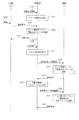
本実施の形態における無線通信システムでは、図6および図7の示す手順で、子機3A,3Bと親機2との間でやり取りされるデータが中継器1により中継転送されることになる。
図6は、無線通信システムのデータ転送動作を示すシーケンス図である。
まず、子機3Aから、送信先として予め設定されている中継器1のMACアドレスを用いて発呼要求が送信される(ステップ110)。中継器1のデータ転送手段11Aは、この自装置宛のデータを受信し、前述した図3のデータ転送処理を実行して当該発呼要求を親機2へ中継転送する(ステップ111)。
[Operation of wireless communication system]
In the wireless communication system according to the present embodiment, the data exchanged between the
FIG. 6 is a sequence diagram showing a data transfer operation of the wireless communication system.
First, a call request is transmitted from the
これに応じて、親機2から中継器1へ発呼許可が送信された場合(ステップ112)、中継器1のデータ転送手段11Aは、この自装置宛のデータを受信し、前述した図3のデータ転送処理を実行して当該発呼許可を子機3Aへ中継転送する(ステップ113)。
子機3Aでは、この発呼許可に応じて、所望のデータの送信を開始し(ステップ114)、中継器1のデータ転送手段11Aは、前述の発呼要求と同様にしてそのデータを親機2へ中継転送する(ステップ115)。
その後、親機2からの終了指示に応じて(ステップ116)、中継器1のデータ転送手段11Aは、前述の発呼許可と同様にして、その終了指示を子機3Aへ中継転送し(ステップ117)、子機3Aでは、この終了指示に応じてデータ送信を終了する。
In response to this, when a call permission is transmitted from the
In response to the call permission, the
Thereafter, in response to the end instruction from the base unit 2 (step 116), the data transfer means 11A of the
また、図7は、親機2からの要求に応じて子機3Aから親機2へデータを送信する場合のデータ転送動作を示すシーケンス図である。
まず、親機2から、送信先として予め設定されている子機3Aの中継用MACアドレスを用いて発呼要求が送信される(ステップ120)。中継器1のデータ転送手段11Aは、この自装置宛のデータを受信し、前述した図3のデータ転送処理を実行して当該発呼要求を子機3Aへ中継転送する(ステップ121)。
FIG. 7 is a sequence diagram showing a data transfer operation when data is transmitted from the
First, a call request is transmitted from the
これに応じて、子機3Aから中継器1へ発呼許可が送信された場合(ステップ122)、中継器1のデータ転送手段11Aは、この自装置宛のデータを受信し、前述した図3のデータ転送処理を実行して当該発呼許可を親機2へ中継転送する(ステップ123)。
親機2では、この発呼許可に応じて、所望のデータの送信を要求するデータ送信要求を送信し(ステップ124)、中継器1のデータ転送手段11Aは、前述の発呼要求と同様にしてそのデータを子機3Aへ中継転送する(ステップ125)。
In response to this, when a call permission is transmitted from the
In accordance with this call permission,
子機3Aでは、このデータ送信要求に応じて、所望のデータの送信を開始し(ステップ126)、中継器1のデータ転送手段11Aは、前述の発呼許可と同様にしてそのデータを親機2へ中継転送する(ステップ127)。
その後、親機2からの終了指示に応じて(ステップ128)、中継器1のデータ転送手段11Aは、前述の発呼要求と同様にして、その終了指示を子機3Aへ中継転送し(ステップ129)、子機3Aでは、この終了指示に応じてデータ送信を終了する。
以上のようにして、子機3A,3Bと親機2との間でやり取りされるデータが中継器1により中継転送される。
In response to this data transmission request,
Thereafter, in response to the end instruction from the base unit 2 (step 128), the data transfer means 11A of the
As described above, the data exchanged between the
[MACアドレス登録処理]
次に、図8を参照して、子機および中継器のMACアドレス登録処理について説明する。図8はMACアドレス登録処理を示すシーケンス図である。
中継器1で子機3A,3Bを中継する場合、中継器1のアドレス管理テーブル13Aに対して子機3A,3BのMACアドレスを登録する必要がある。また、親機2のアドレス管理テーブル(図示せず)に対しても、中継器1および子機3A,3Bの中継用MACアドレスを登録する必要がある。これらMACアドレス登録については手作業で実施してもよいが、ここでは、登録処理として自動で中継器1のアドレス登録手段11Bが行う場合について説明する。
[MAC address registration processing]
Next, with reference to FIG. 8, the MAC address registration process of a subunit | mobile_unit and a repeater is demonstrated. FIG. 8 is a sequence diagram showing the MAC address registration process.
When the
まず、中継器1の制御部11は、操作入力部15からの登録受付開始操作に応じて(ステップ150)、中継対象子機3A,3Bからのアドレス登録受付を開始し、表示部14で受付中を示す表示を開始する(ステップ151)。この後、子機3Aでの登録操作に応じて(ステップ152)、子機3Aから登録要求が送信される(ステップ153)。
中継器1のアドレス登録手段11Bでは、子機3Aからの登録要求を無線通信I/F部12を介して受け取り、その登録要求に付与されている送信元アドレスから子機3AのMACアドレスを取得し、そのMACアドレスを固有の管理番号と対応付けてアドレス管理テーブル13Aへ登録する(ステップ154)。
First, the
The
そして、登録完了を示す登録応答を無線通信I/F部12から子機3Aへ送信する(ステップ155)。この後、操作入力部15からの受付終了操作に応じて(ステップ156)、アドレス登録受付処理を終了し、表示部14で受付中を示す表示を終了する(ステップ157)。
次に、アドレス登録手段11Bは、自装置のMACアドレスを親機2に登録するための登録要求を無線通信I/F部12から親機2へ送信する(ステップ160)。親機2は、この登録要求に応じて、その登録要求に付与されている中継器1のMACアドレスを、親機2のアドレス管理テーブル(図示せず)に登録し(ステップ161)、登録完了を示す登録応答を中継器1へ送信する(ステップ162)。
Then, a registration response indicating completion of registration is transmitted from the wireless communication I /
Next, the
これに応じて、中継器1のアドレス登録手段11Bは、アドレス管理テーブル13Aに登録された子機3AのMACアドレスに対応する管理番号と自装置のMACアドレスとから、子機3Aの中継用MACアドレスを生成し(ステップ163)、この中継用MACアドレスを親機2に登録するための登録要求を無線通信I/F部12から親機2へ送信する(ステップ164)。親機2は、この登録要求に応じて、その登録要求に付与されている子機3Aの中継用MACアドレスを、親機2のアドレス管理テーブル(図示せず)に登録し(ステップ165)、登録完了を示す登録応答を中継器1へ送信する(ステップ166)。
In response to this, the address registration means 11B of the
これに応じて、中継器1のアドレス登録手段11Bは、親機2での登録結果を表示部14で表示し、一連のアドレス登録処理を終了する。
このようにして、中継器1のアドレス登録手段11Bで、子機MACアドレスの中継器1に対する登録と、中継器MACアドレスおよび子機中継用MACアドレスの親機2に対する登録とを自動的に行うようにしたので、中継器1の追加に伴う中継器1および親機2での煩雑なMACアドレス登録の作業負担を軽減できる。
In response to this, the
In this way, the
[第2の実施の形態の構成]
次に、図9を参照して、本発明の第2の実施の形態にかかる無線端末装置について説明する。図9は本発明の第2の実施の形態にかかる無線端末装置の構成を示すブロック図である。なお、図9において、前述した第1の実施の形態(図1参照)と同じまたは同等部分には同一符号を付してある。
前述した第1の実施の形態では、子機3A,3Bに予め送信先として中継器1のMACアドレスを設定しておくとともに、親機2に予め送信先として中継器1の中継用MACアドレスを設定し、これら子機3A,3Bと親機2との間を固定的に定められた中継器1で中継する場合について説明した。
[Configuration of Second Embodiment]
Next, with reference to FIG. 9, the radio | wireless terminal apparatus concerning the 2nd Embodiment of this invention is demonstrated. FIG. 9 is a block diagram showing a configuration of a wireless terminal apparatus according to the second embodiment of the present invention. In FIG. 9, the same or equivalent parts as those in the first embodiment (see FIG. 1) described above are denoted by the same reference numerals.
In the first embodiment described above, the MAC address of the
本実施の形態では、子機3A,3Bからの転送要求に応じて、その送信先へ転送可能な中継器1Aがこれに応答して、これら子機3A,3Bと親機2との間を中継器1Aで中継する場合について説明する。
図9の無線端末装置1A(以下、中継器という)は、前述の中継器1と比較して、制御部11の機能手段と記憶部13のアドレス管理テーブルが異なる以外、同様の構成をなしている。
In the present embodiment, in response to a transfer request from the
The
中継器1Aの制御部11には、機能手段として、データ転送手段11Cと接続確認手段11Dとが設けられている。
データ転送手段11Cは、転送確認要求を無線通信I/F部12で受信した場合、その転送確認要求で指定されている所望の送信先と自中継器1Aとが無線通信可能である場合は、その後、その転送確認要求の送信元からのデータを中継転送する。
接続確認手段11Dは、転送確認要求で指定された所望の送信先に対して接続確認要求を無線通信I/F部12を介して送信することにより、当該送信先と自中継器1Aとが無線通信可能か否かを確認する。
The
When the wireless transfer I /
The
この無線通信システムでは、データの送信元アドレスおよび送信先アドレスを示す情報として、MACアドレスを付与するものとなっている。また、当該データには、中継器アドレスを示す情報として、MACアドレスを付与するものとなっている。図10に子機、親機および中継器の間で送受信されるデータの構成例を示す。このデータには、ヘッダ部50に、送信元装置を示す送信元MACアドレス51、送信先装置を示す送信先MACアドレス52、中継器を示す中継器MACアドレス53、当該データの信号種別を示す制御コード54、当該データで通知したい制御情報を示すフラグ55などが記載される。また、データ部56には、子機3A〜3Cから親機2へ収集するデータなど各種データが記載される。
In this wireless communication system, a MAC address is assigned as information indicating a data transmission source address and a transmission destination address. In addition, a MAC address is given to the data as information indicating a repeater address. FIG. 10 shows a configuration example of data transmitted and received between the slave unit, the master unit, and the repeater. In this data, the
本実施の形態では、子機3A,3Bから親機2へのデータを中継器1Aで中継転送する場合、中継器1Aのデータ転送手段11Cで、中継転送の必要性を判断して自動的に中継転送を行う。このときデータ転送手段11Cでは、中継対象として判断した送信元装置のMACアドレスを記憶部13のアドレス管理テーブル13Bへ登録しておく。
図11にアドレス管理テーブル13Bの構成例を示す。この例では、中継対象と判断した子機3A,3BのMACアドレスが登録されている。
したがって、受信したデータの送信元アドレスがアドレス管理テーブル13Bに登録されているものについては、すべて当該中継器1Aで中継転送される。
In the present embodiment, when data from the
FIG. 11 shows a configuration example of the address management table 13B. In this example, the MAC addresses of the
Accordingly, all the transmission source addresses of the received data registered in the address management table 13B are relayed and transferred by the
この場合、子機3A,3Bから親機2へ転送するデータは、前述した実施の形態のような送信元および送信先アドレスの置換は行わない。但し、親機2から子機3A,3Bへ送信されるデータについて、自装置で中継転送すべきか否かを判定するため、中継器MACアドレス3に当該中継器1AのMACアドレスを記載して、子機3A,3Bからのデータを親機2へ転送する。これにより、親機2から子機3A,3Bへのデータの中継器MACアドレスに、当該中継器1AのMACアドレスが記載されることになり、これにより自装置で中継転送すべきか否かを判定できる。
なお、子機3A,3Bへ転送するデータに、中継器MACアドレスを記載する必要はない。
In this case, the data transferred from the
Note that it is not necessary to describe the repeater MAC address in the data transferred to the
[第2の実施の形態の動作]
次に、図12を参照して、本実施の形態にかかる中継器1Aのデータ転送処理について説明する。図12は、本実施の形態にかかる中継器1Aのデータ転送処理を示すシーケンス図である。ここでは、子機3Aと親機2との間を中継器1Aで中継する場合を例として説明する。
まず、子機3Aは、親機2との間で無線接続が困難な場合、いずれかの中継器に対して転送要求を行うため、ヘッダ部50のフラグ55で転送要求フラグをセットした転送確認要求を、親機2宛に送信する(ステップ200)。
[Operation of Second Embodiment]
Next, with reference to FIG. 12, the data transfer process of the
First, the
中継器1Aのデータ転送手段11Cは、無線通信I/F部12で、他の子機3A,3Bから送信されたデータを常時監視しており、子機3Aから送信されたデータが受信された場合は、そのデータの転送要求フラグの設定有無を確認する(ステップ201)。ここで、転送要求フラグが設定されている場合は(ステップ201:YES)、その転送確認要求の送信先アドレスから親機2のMACアドレスを取得し、接続確認手段11Dへ渡す。
これに応じて、接続確認手段11Dは、当該MACアドレスを送信先アドレスとする接続確認要求を無線通信I/F部12から送信し、自装置と送信先ここでは親機2との無線接続の可否を確認する(ステップ202)。
The data transfer means 11C of the
In response to this, the
親機2は、この接続確認要求の受信に応じて、その送信元である中継器1Aとの接続可否を判断する(ステップ203)。そして、接続可の場合には(ステップ203:YES)、接続確認応答を中継器1Aへ返送する(ステップ204)。
中継器1Aの接続確認手段11Dは、その接続確認応答の受信に応じて、親機2との無線接続が可能であることをデータ転送手段11Cへ通知する。
データ転送手段11Cは、これに応じて、先の転送確認要求の送信元である子機3AのMACアドレスを中継対象として記憶部13のアドレス管理テーブルへ登録し(ステップ205)、子機3Aへ転送確認応答を返送する(ステップ206)。
In response to the reception of this connection confirmation request,
In response to receiving the connection confirmation response, the
In response to this, the data transfer means 11C registers the MAC address of the
子機3Aは、この転送確認応答に応じて、親機2に対するデータの送信を開始する(ステップ206)。この際、データの送信先アドレスとして、中継器1ではなく親機2のMACアドレスが用いられる。
中継器1Aのデータ転送手段11Cは、子機3Aからのデータのヘッダ部をまず受信してその送信元アドレスを取得し、その送信元アドレスがアドレス管理テーブル13Bに登録されている場合には(ステップ211:YES)、そのデータが中継対象であると判断し、そのデータを順次受信して記憶部13へ一旦格納する(ステップ212)。
In response to this transfer confirmation response,
The data transfer means 11C of the
そして、データ受信完了後、記憶部13から当該データを読み出し(ステップ213)、その中継器MACアドレスに自装置のMACアドレスを記載し、無線通信I/F部12から親機2へ送信する(ステップ214)。
これにより、子機3Aから親機2へ送信されたデータが、中継器1Aで中継されて親機2へ転送される。
After the data reception is completed, the data is read from the storage unit 13 (step 213), the MAC address of the own device is described in the repeater MAC address, and transmitted from the wireless communication I /
Thereby, the data transmitted from the
また、親機2から子機3Aへデータが送信された場合は(ステップ220)、中継器1Aのデータ転送手段11Cで、そのデータのヘッダ部から中継器MACアドレスが取得され、そのMACアドレスが自装置のMACアドレスと一致するか否か判断される(ステップ221)。
ここで、MACアドレスが一致した場合は(ステップ221:YES)、自装置で中継すべきデータであると判断し、そのデータを順次受信して記憶部13へ一旦格納する(ステップ222)。
そして、データ受信完了後、記憶部13から当該データを読み出し(ステップ223)、無線通信I/F部12から子機3Aへ送信する(ステップ224)。
When data is transmitted from the
If the MAC addresses match (step 221: YES), it is determined that the data is to be relayed by the own device, and the data is sequentially received and temporarily stored in the storage unit 13 (step 222).
After the data reception is completed, the data is read from the storage unit 13 (step 223), and transmitted from the wireless communication I /
このように、本実施の形態では、無線端末装置(子機)と無線基地局(親機)との間に中継用の無線端末装置(中継器)を設け、そのデータ転送手段で、無線端末装置(子機)から受信したデータに中継転送を要求する転送要求情報(転送要求フラグ)が含まれている場合には、無線通信手段を介して要求元の無線端末装置へ転送許可データを送信し、これに応じて当該無線端末装置から送信されたデータを転送するようにしたので、既存の無線基地局と無線接続が不可能となった子機からデータを収集するため新たな無線基地局を別途設ける必要がなくなる。また、無線基地局で収集したデータを公衆通信網を介して遠隔地にあるセンタ装置で収集して利用する場合でも、回線利用コストの増加も回避できる。したがって、大幅なコストアップを必要とすることなく無線通信システムの規模を拡張できる。 As described above, in this embodiment, a wireless terminal device (relay device) for relay is provided between a wireless terminal device (child device) and a wireless base station (parent device), and the data transfer means uses the wireless terminal device. When the data received from the device (slave unit) includes transfer request information (transfer request flag) for requesting relay transfer, the transfer permission data is transmitted to the requesting wireless terminal device via the wireless communication means. In response to this, since the data transmitted from the wireless terminal device is transferred, a new wireless base station is collected in order to collect data from the slave unit that cannot wirelessly connect to the existing wireless base station. Need not be provided separately. Further, even when data collected by a radio base station is collected and used by a center device at a remote location via a public communication network, an increase in line use cost can be avoided. Therefore, the scale of the wireless communication system can be expanded without requiring a significant cost increase.
また、中継用の無線端末装置が、自身で中継要否を判断するため、無線端末装置では、中継先として何れかの無線端末装置を予め固定的に設定する必要がなくなり、中継用の無線端末装置を固定的に設定する場合と比較して、中継用の無線端末装置の故障などにより中継不可となった場合でも、他の中継用の無線端末装置で柔軟に対応でき、無線通信システムの安定性を高めることができる。さらに、各無線端末装置ごとに個別に中継用の無線端末装置のMACアドレスを設定する必要がなくなり、作業負担を軽減できる。 In addition, since the relay wireless terminal device itself determines whether or not relaying is necessary, it is not necessary for the wireless terminal device to set any wireless terminal device as a relay destination in advance. Compared with the case where the device is fixedly set, even if relaying is not possible due to a failure of the wireless terminal device for relaying, other wireless terminal devices for relaying can flexibly cope with the stability of the wireless communication system. Can increase the sex. Furthermore, it is not necessary to set the MAC address of the wireless terminal device for relay individually for each wireless terminal device, and the work load can be reduced.
また、転送要求があった際、接続確認手段で、その転送先と当該中継用の無線端末装置との間の無線接続可否を確認し、その結果に応じて転送要求元の無線端末装置に対して中継可否を通知するようにしたので、要求された転送先と当該中継用の無線端末装置との間で無線接続ができる場合にのみ、中継転送が開始されることにより、要求された転送先に対して確実に対応できる。 In addition, when there is a transfer request, the connection confirmation means confirms whether or not the wireless connection between the transfer destination and the wireless terminal device for relay is possible, and depending on the result, the wireless terminal device of the transfer request source Because the relay transfer is started, relay transfer is started only when a wireless connection can be established between the requested transfer destination and the wireless terminal device for relay. Can be dealt with reliably.
[第3の実施の形態の構成]
次に、図13を参照して、本発明の第3の実施の形態にかかる無線端末装置について説明する。図13は本発明の第3の実施の形態にかかる無線端末装置の構成を示すブロック図である。
前述した第2の実施の形態(図9参照)では、子機3A,3Bからの転送要求に応じて、その送信先へ転送可能な中継器1Aがこれに応答して、これら子機3A,3Bと親機2との間を中継器1Aで中継する場合について説明した。
本実施の形態は、他の子機の通信状況に基づき、データ送信元となる子機が中継先となる子機を選択して、そのデータの転送を要求する場合について説明する。
[Configuration of Third Embodiment]
Next, with reference to FIG. 13, the radio | wireless terminal apparatus concerning the 3rd Embodiment of this invention is demonstrated. FIG. 13: is a block diagram which shows the structure of the radio | wireless terminal apparatus concerning the 3rd Embodiment of this invention.
In the second embodiment described above (see FIG. 9), in response to a transfer request from the
In the present embodiment, a case will be described in which a slave unit that is a data transmission source selects a slave unit that is a relay destination based on the communication status of other slave units and requests transfer of the data.
本実施の形態では、各無線端末装置7A〜7D(以下、子機という)が、他の子機のデータを中継する中継機能を有しており、子機7B〜7Dは、子機7Aと同じ構成を有している。なお、この中継機能については、すべての子機が有している必要はなく、少なくとも中継が必要な箇所に設置されている子機が中継機能を持っていればよい。
図13の子機7Aには、制御部71、無線通信I/F部72、記憶部73、およびデータ入出力I/F部74が設けられている。
In the present embodiment, each of the
A
制御部71は、CPUなどのマイクロプロセッサとその周辺回路からなり、記憶部73やCPU内部に予め格納されているプログラムを実行することにより、各種機能手段を実現する。
この機能手段として、データ送受信手段71A、データ転送手段71B、およびアドレス取得手段71Cが設けられている。
データ送受信手段71Aは、データ入出力I/F部74で外部の装置(図示せず)から取り込んだデータを、無線通信I/F部72を介して親機2や他の子機7B〜7Dへ送信するとともに、無線通信I/F部72を介して親機2や他の子機7B〜7Dからのデータを受信する。
The
As this functional means, a data transmission / reception means 71A, a data transfer means 71B, and an address acquisition means 71C are provided.
The data transmission / reception means 71A receives data taken from an external device (not shown) by the data input / output I /
無線通信I/F部72は、特定小電力無線、ブルーツース、コードレス無線、無線LANなどの無線方式に基づき無線信号を送受信することにより、無線回線を介して親機2や他の子機7B〜7Dと無線通信を行う回路部である。
記憶部73は、メモリやハードディスクなどの記憶装置からなり、他の子機の通信状況から取得したアドレスを管理するアドレス管理テーブル73Aのほか、通信相手となる親機2のMACアドレス、および自装置のMACアドレスなど、制御部71での処理に用いる各種情報を記憶する。メモリとしてCPUの内部メモリを用いてもよい。
データ入出力I/F部74は、外部の装置と接続して各種データをやり取りする回路部である。
The wireless communication I /
The
The data input / output I /
この無線通信システムでは、データの送信元アドレスおよび送信先アドレスを示す情報として、MACアドレスを付与するものとなっている。図14に子機間、および子機−親機の間で送受信されるデータの構成例を示す。このデータには、ヘッダ部80に、送信元装置を示す送信元MACアドレス81、送信先装置を示す送信先MACアドレス82、中継器を示す中継器MACアドレス83、当該データの信号種別を示す制御コード84などが記載される。また、データ部85には、子機7A〜7Dから親機2へ収集するデータなど各種データが記載される。
In this wireless communication system, a MAC address is assigned as information indicating a data transmission source address and a transmission destination address. FIG. 14 shows a configuration example of data transmitted and received between the slave units and between the slave unit and the master unit. In this data, in the
本実施の形態では、子機7A,7Bから親機2へのデータを子機7Dで中継転送する場合、子機7A,7Bのアドレス取得手段71Cで、子機7Dの通信状況を監視して、自装置が所望する送信先すなわち親機2と無線接続可能に子機7C7Dを確認し、これら子機7C,7DのMACアドレスをその送信先となる親機2と関連付けて、記憶部73のアドレス管理テーブル73Aへ登録する。
図15に、アドレス管理テーブル73Aの構成例を示す。この例では、監視した子機7C,7Dでのデータ通信ごとに、そのデータの送信元となる子機のMACアドレスと、送信先となる親機2のMACアドレスとが対として登録されている。
In the present embodiment, when relaying and transferring data from the
FIG. 15 shows a configuration example of the address management table 73A. In this example, for each data communication in the monitored
子機7A,7Bでは、親機2と無線接続できない場合、アドレス管理テーブル73Aから当該送信先に対応する送信元MACアドレスを取得し、そのMACアドレスの子機に対して転送要求を行う。
この場合、アドレス取得手段71でのアドレス取得処理については、前もって実行しておいてもよく、無線接続できない場合にのみ実行して中継先を見つけるようにしてもよい。
If the
In this case, the address acquisition process in the
[第3の実施の形態の動作]
次に、図16を参照して、本実施の形態にかかる子機7Aのアドレス取得処理およびデータ送受信処理について説明する。図16は、本実施の形態にかかる子機7Aのアドレス取得処理およびデータ送受信処理を示すシーケンス図である。ここでは、子機7Aと親機2との間を子機7Dで中継する場合を例として説明する。
まず、子機7Aのアドレス取得手段71Cでは、無線通信I/F部72で受信されたデータから他の子機7B〜7Dの通信状況を監視する。そして、親機2と正常に無線通信している子機から送信されたデータについて(ステップ301:YES)、その送信元および送信先アドレスを取得し、記憶部73のアドレス管理テーブル73Aへ登録する(ステップ302)。
[Operation of Third Embodiment]
Next, with reference to FIG. 16, an address acquisition process and a data transmission / reception process of the
First, the address acquisition means 71C of the
次に、子機7Aのデータ送受信手段71Aで、親機2へ任意のデータを送信し(ステップ310)、その送信から所定期間内に親機2から応答が得られずタイムアウトとなった場合(ステップ311:YES)、データ送受信手段71Aは、記憶部73のアドレス管理テーブル73Aから、当該送信先である親機2に対応する送信元アドレスを選択し、その送信元アドレスを中継器MACアドレスとして当該データに設定し(ステップ312)、無線通信I/F部72から送信する(ステップ313)。
Next, the data transmission / reception means 71A of the
子機7Dのデータ転送手段71Bは、このデータを無線通信I/F部72を介して受信し、そのヘッダ部の中継器MACアドレスが自装置のMACアドレスと一致するか確認する(ステップ314)。
ここで、自装置のMACアドレスと一致した場合は(ステップ314:YES)、そのデータを順次受信して記憶部73へ一旦格納する(ステップ315)。
そして、データ受信完了後、記憶部73から当該データを読み出し(ステップ316)、無線通信I/F部72から親機2へ送信する(ステップ317)。
The data transfer means 71B of the
Here, when it coincides with the MAC address of its own device (step 314: YES), the data is sequentially received and temporarily stored in the storage unit 73 (step 315).
After the data reception is completed, the data is read from the storage unit 73 (step 316), and transmitted from the wireless communication I /
また、親機2から子機7Aへ送信されたデータが受信された場合にも、前述と同様のステップ314〜317により、その中継器MACアドレスと自装置のMACアドレスが比較され、その一致に応じて、当該データが子機7Aへ中継転送される。
これにより、子機7Aから親機2へ送信されたデータが、子機7Dで中継されて親機2へ転送されるとともに、親機2か子機7Aへ送信されたデータが、子機7Dで中継されて子機7Aへ転送される。
Also, when the data transmitted from the
Thereby, the data transmitted from the
このように、本実施の形態では、無線端末装置(子機)と無線基地局(親機)との間に、無線端末装置(子機)からの要求に応じてデータを中継転送する無線端末装置(中継器)を設け、無線通信手段で受信されたデータに付与されている中継器MACアドレスが自装置のMACアドレスと一致した場合にのみ、当該データの転送を行うようにしたので、各データごとに中継器として指定された無線端末装置(中継器)で、データが中継され無線基地局へ転送される。 As described above, in the present embodiment, a wireless terminal that relays and transfers data between a wireless terminal device (slave unit) and a wireless base station (master unit) in response to a request from the wireless terminal device (slave unit). Since the device (repeater) is provided, and the data is transferred only when the repeater MAC address assigned to the data received by the wireless communication means matches the MAC address of the own device. Data is relayed and transferred to the wireless base station by a wireless terminal device (relay) designated as a repeater for each data.
また、無線端末装置(子機)のアドレス管理テーブルで、データ中継転送の要求先を示す無線端末装置のMACアドレスに、データ送信先を示す無線基地局のMACアドレスを関連付けて予め管理しておき、データ送受信手段で、無線基地局と無線接続できない場合、当該無線基地局のMACアドレスに対応する無線端末装置のMACアドレスをアドレス管理テーブルから取得し、そのMACアドレスの無線端末装置に対してデータの中継転送を要求する転送要求情報を無線通信手段を介して送信するようにしたので、データ送信元が必要に応じて適当な無線端末装置(中継器)を選択される。 Further, in the address management table of the wireless terminal device (slave device), the MAC address of the wireless base station indicating the data transmission destination is associated with the MAC address of the wireless terminal device indicating the request destination of data relay transfer in advance and managed in advance. If the data transmission / reception means cannot establish a wireless connection with the wireless base station, the MAC address of the wireless terminal device corresponding to the MAC address of the wireless base station is obtained from the address management table, and data is transmitted to the wireless terminal device of the MAC address. Since the transfer request information for requesting the relay transfer is transmitted via the wireless communication means, the data transmission source selects an appropriate wireless terminal device (relay device) as necessary.
これにより、既存の無線基地局と無線接続が不可能となった子機からデータを収集するため新たな無線基地局を別途設ける必要がなくなる。また、無線基地局で収集したデータを公衆通信網を介して遠隔地にあるセンタ装置で収集して利用する場合でも、回線利用コストの増加も回避できる。したがって、大幅なコストアップを必要とすることなく無線通信システムの規模を拡張できる。 As a result, it is not necessary to separately provide a new radio base station in order to collect data from the slave units that are unable to establish a radio connection with the existing radio base station. Further, even when data collected by a radio base station is collected and used by a center device at a remote location via a public communication network, an increase in line use cost can be avoided. Therefore, the scale of the wireless communication system can be expanded without requiring a significant cost increase.
また、無線端末装置(子機)のアドレス取得手段で、他の無線端末装置と無線基地局との間でやり取りされているデータを監視し、そのデータから当該他の無線端末装置と無線基地局にそれぞれ固有のMACアドレスを取得して、これらMACアドレスを関連付けてアドレス管理テーブルへ格納するようにしたので、自装置の中継器として機能する無線端末装置のMACアドレスを自動的に取得でき、各無線端末装置ごとに個別に中継用の無線端末装置のMACアドレスを設定する必要がなくなり、作業負担を軽減できる。 In addition, the address acquisition means of the wireless terminal device (slave unit) monitors data exchanged between the other wireless terminal device and the wireless base station, and from the data, the other wireless terminal device and the wireless base station are monitored. Since each MAC address is acquired and the MAC address is associated and stored in the address management table, the MAC address of the wireless terminal device functioning as a repeater of the own device can be automatically acquired. It is not necessary to set the MAC address of the wireless terminal device for relay individually for each wireless terminal device, and the work load can be reduced.
この際、無線端末装置(子機)からの中継要求が受け付けられなかった場合には、データ送受信手段で、アドレス管理テーブルから送信先となる無線基地局のMACアドレスに対応する他の無線端末装置のMACアドレスを選択して中継要求を行うようにしてもよく、中継用の無線端末装置を固定的に設定する場合と比較して、中継用の無線端末装置の故障などにより中継不可となった場合でも、他の中継用の無線端末装置で柔軟に対応でき、無線通信システムの安定性を高めることができる。 At this time, if the relay request from the wireless terminal device (slave device) is not accepted, the data transmitting / receiving means causes another wireless terminal device corresponding to the MAC address of the wireless base station to be the transmission destination from the address management table. It is possible to make a relay request by selecting the MAC address of the relay, and compared to the case where the wireless terminal device for relay is fixedly set, relay becomes impossible due to a failure of the wireless terminal device for relay, etc. Even in this case, it is possible to flexibly deal with other wireless terminal devices for relay, and the stability of the wireless communication system can be improved.
なお、前述した第1および第2の実施の形態では、中継器1,1Aとして、中継転送専用の通信端末装置を用いた場合を例として説明したが、データを親機2へ送信する子機3A〜3Cに、データ中継転送機能として、データ転送手段やアドレス管理テーブルを設けて、子機3A〜3Cのいずれかまたは全部で中継器1,1Aの機能を兼用してもよい。
In the first and second embodiments described above, a case where a communication terminal device dedicated to relay transfer is used as the
また、前述した各実施の形態では、各子機からのデータを無線回線を介して親機へ収集するデータ通信システムを例として説明したが、これに限定されるものではない。例えば、子機、親機、および中継器の間で用いるデータ通信手段としては、無線通信ではなく有線通信など他のデータ通信手段を用いてもよく、前述と同様の作用効果が得られる。また、子機のデータを親機で収集するのではなく、2つの通信端末装置間で所望のデータをやり取りする場合、あるいは親機から各子機へデータを配信する場合にも、本発明を適用でき、前述と同様の作用効果が得られる。 In each of the above-described embodiments, the data communication system that collects data from each slave unit to the master unit via a wireless line has been described as an example. However, the present invention is not limited to this. For example, as the data communication means used between the child device, the parent device, and the repeater, other data communication means such as wired communication may be used instead of wireless communication, and the same effect as described above can be obtained. The present invention is also applicable to a case where desired data is exchanged between two communication terminal devices, instead of collecting data of the child device at the parent device, or when data is distributed from the parent device to each child device. It can be applied and the same effects as described above can be obtained.
1,1A…無線端末装置(中継器)、11…制御部、11A,11C…データ転送手段、11B…アドレス登録手段、11D…接続確認手段、12…無線通信I/F部、13…記憶部、13A,13B…アドレス管理テーブル、14…表示部、15…操作入力部、2…無線基地局(親機)、3A,3B,3C,3D…無線端末装置(子機)、31…制御部、31A…データ送受信手段、32…無線通信I/F部、33…記憶部、34…データ入出力I/F部、7A,7B,7C,7D…無線端末装置(子機/中継器)、71…制御部、71A…データ送受信手段、71B…データ転送手段、71C…アドレス取得手段、72…無線通信I/F部、73…記憶部、73A…アドレス管理テーブル、74…データ入出力I/F部。
DESCRIPTION OF
Claims (2)
他の無線端末装置および無線基地局と無線通信を行う無線通信手段と、
各種データを記憶する記憶手段と、
前記無線通信手段で受信したデータを前記記憶部に一旦格納するとともに、格納したデータを前記記憶部から読み出し無線通信手段を介して当該データの送信先へ転送するデータ中継手段と、
前記無線基地局と自装置との間の無線接続可否を確認する接続確認手段とを備え、
前記データ中継手段は、前記他の無線端末装置から送信されたデータを前記無線通信手段で監視し、そのデータに中継転送を要求する転送要求情報が含まれている場合には、前記接続確認手段により前記データの送信先となる前記無線基地局と自装置との間で無線接続の可能を確認した後、前記無線通信手段を介して当該他の無線端末装置へ転送許可データを送信し、これに応じて当該他の無線端末装置から送信されたデータの転送を行う
ことを特徴とする無線端末装置。 Used in a wireless communication system that exchanges various types of data between a plurality of wireless terminal devices and a wireless base station via wireless communication, and relays and transfers data exchanged between these wireless terminal devices and the wireless base station A wireless terminal device,
Wireless communication means for performing wireless communication with other wireless terminal devices and wireless base stations;
Storage means for storing various data;
Data relay means for temporarily storing the data received by the wireless communication means in the storage unit, and reading the stored data from the storage unit to the destination of the data via the wireless communication means;
Connection confirmation means for confirming whether or not wireless connection between the wireless base station and the own device is possible,
The data relay means monitors the data transmitted from the other wireless terminal device by the wireless communication means, and when the data includes transfer request information for requesting relay transfer, the connection confirmation means After confirming that wireless connection is possible between the wireless base station that is the transmission destination of the data and its own device, transfer permission data is transmitted to the other wireless terminal device via the wireless communication means, A wireless terminal device that transfers data transmitted from the other wireless terminal device according to the above.
中継対象となる前記他の無線端末装置に固有のMACアドレスを管理するアドレス管理テーブルをさらに備え、
前記データ中継手段は、前記接続確認手段により、前記データの送信先となる前記無線基地局と自装置との間で無線接続の可能を確認した後、前記他の無線端末装置のMACアドレスを中継対象として前記アドレス管理テーブルへ登録し、前記無線通信手段で受信した前記他の無線端末装置から前記無線基地局へ送信されたデータに付与されている送信元アドレスが前記アドレス管理テーブルに登録されているMACアドレスのいずれかと一致した場合にのみ、当該データを前記無線基地局へ転送する
ことを特徴とする無線端末装置。 In claim 1,
An address management table for managing a MAC address unique to the other wireless terminal device to be relayed;
The data relay means relays the MAC address of the other wireless terminal apparatus after confirming the wireless connection possibility between the wireless base station that is the data transmission destination and the own apparatus by the connection confirmation means. Registered in the address management table as a target, and the source address given to the data transmitted from the other wireless terminal device received by the wireless communication means to the wireless base station is registered in the address management table. The wireless terminal device, wherein the data is transferred to the wireless base station only when it matches one of the existing MAC addresses.
Priority Applications (1)
| Application Number | Priority Date | Filing Date | Title |
|---|---|---|---|
| JP2008208440A JP4893710B2 (en) | 2008-08-13 | 2008-08-13 | Wireless terminal device |
Applications Claiming Priority (1)
| Application Number | Priority Date | Filing Date | Title |
|---|---|---|---|
| JP2008208440A JP4893710B2 (en) | 2008-08-13 | 2008-08-13 | Wireless terminal device |
Related Parent Applications (1)
| Application Number | Title | Priority Date | Filing Date |
|---|---|---|---|
| JP2003165244A Division JP4269789B2 (en) | 2003-06-10 | 2003-06-10 | Wireless terminal device |
Publications (2)
| Publication Number | Publication Date |
|---|---|
| JP2009010977A true JP2009010977A (en) | 2009-01-15 |
| JP4893710B2 JP4893710B2 (en) | 2012-03-07 |
Family
ID=40325512
Family Applications (1)
| Application Number | Title | Priority Date | Filing Date |
|---|---|---|---|
| JP2008208440A Expired - Lifetime JP4893710B2 (en) | 2008-08-13 | 2008-08-13 | Wireless terminal device |
Country Status (1)
| Country | Link |
|---|---|
| JP (1) | JP4893710B2 (en) |
Cited By (3)
| Publication number | Priority date | Publication date | Assignee | Title |
|---|---|---|---|---|
| JP2016525812A (en) * | 2013-05-16 | 2016-08-25 | ソニー株式会社 | Operation method of terminal device in wireless communication system |
| JP2018050213A (en) * | 2016-09-23 | 2018-03-29 | Necプラットフォームズ株式会社 | Repeater |
| US11131975B2 (en) | 2017-06-12 | 2021-09-28 | Mitsubishi Electric Corporation | Air conditioning system and communication method for wired and wireless message transmission |
Citations (4)
| Publication number | Priority date | Publication date | Assignee | Title |
|---|---|---|---|---|
| JPH0832504A (en) * | 1994-07-12 | 1996-02-02 | Canon Inc | Radio network system |
| JP2000031895A (en) * | 1998-05-08 | 2000-01-28 | Matsushita Electric Ind Co Ltd | Communication terminal device and communication method therefor |
| JP2002198892A (en) * | 2000-12-27 | 2002-07-12 | Hitachi Kokusai Electric Inc | Radio repeating system |
| JP2003016563A (en) * | 2001-07-02 | 2003-01-17 | Japan Radio Co Ltd | Uui utilized radio automatic meter reading system and gateway thereof |
-
2008
- 2008-08-13 JP JP2008208440A patent/JP4893710B2/en not_active Expired - Lifetime
Patent Citations (4)
| Publication number | Priority date | Publication date | Assignee | Title |
|---|---|---|---|---|
| JPH0832504A (en) * | 1994-07-12 | 1996-02-02 | Canon Inc | Radio network system |
| JP2000031895A (en) * | 1998-05-08 | 2000-01-28 | Matsushita Electric Ind Co Ltd | Communication terminal device and communication method therefor |
| JP2002198892A (en) * | 2000-12-27 | 2002-07-12 | Hitachi Kokusai Electric Inc | Radio repeating system |
| JP2003016563A (en) * | 2001-07-02 | 2003-01-17 | Japan Radio Co Ltd | Uui utilized radio automatic meter reading system and gateway thereof |
Cited By (4)
| Publication number | Priority date | Publication date | Assignee | Title |
|---|---|---|---|---|
| JP2016525812A (en) * | 2013-05-16 | 2016-08-25 | ソニー株式会社 | Operation method of terminal device in wireless communication system |
| US10219304B2 (en) | 2013-05-16 | 2019-02-26 | Sony Corporation | Operating a terminal device in a wireless communication system |
| JP2018050213A (en) * | 2016-09-23 | 2018-03-29 | Necプラットフォームズ株式会社 | Repeater |
| US11131975B2 (en) | 2017-06-12 | 2021-09-28 | Mitsubishi Electric Corporation | Air conditioning system and communication method for wired and wireless message transmission |
Also Published As
| Publication number | Publication date |
|---|---|
| JP4893710B2 (en) | 2012-03-07 |
Similar Documents
| Publication | Publication Date | Title |
|---|---|---|
| US8233424B2 (en) | Wireless communication system, connection device, relay device and registering method | |
| KR100906504B1 (en) | Wireless communication system, wireless lan access point and settings confirmation/change method used therefor | |
| JP4490499B2 (en) | Communication terminal, relay device, wireless communication system, wireless communication control method, and program | |
| JP2013175916A5 (en) | ||
| JP4893710B2 (en) | Wireless terminal device | |
| JP4269789B2 (en) | Wireless terminal device | |
| KR20120016120A (en) | Method, device and system for information synchronization | |
| CN103825789A (en) | Bus system, method for operating bus system and fluid system with bus system | |
| JP2009177410A (en) | Mobile communication system, base-station control device, base station, and communication connection method | |
| JP5867236B2 (en) | Data collection method, mobile terminal and data storage device | |
| JP6161006B2 (en) | Meter reading device | |
| JP4042632B2 (en) | Communication terminal device | |
| JP2007199761A (en) | Radio telemeter system | |
| JP2014207608A (en) | Radio relay system between ieee802.11 standard communication and ieee802.15.4 standard communication | |
| WO2007102328A1 (en) | Communication device connection apparatus | |
| JP2008061079A (en) | Wireless system | |
| KR20170025550A (en) | Gateway and control method thereof | |
| JP2005348083A (en) | Data communication system | |
| JP6234848B2 (en) | Wireless communication system, wireless communication device, and wireless device | |
| CN111478830A (en) | Remote operation system, communication device, and computer program | |
| JP2003009226A (en) | System and method for automatically registering phs master and slave | |
| JP2005354179A (en) | Communication system, communication method, wireless base station, and relaying wireless terminal | |
| JP2012029159A (en) | Wireless communication system | |
| JP5121640B2 (en) | Wireless communication system and wireless communication method | |
| JP2010062855A (en) | Health check in wireless communications network |
Legal Events
| Date | Code | Title | Description |
|---|---|---|---|
| A131 | Notification of reasons for refusal |
Free format text: JAPANESE INTERMEDIATE CODE: A131 Effective date: 20101130 |
|
| A521 | Request for written amendment filed |
Free format text: JAPANESE INTERMEDIATE CODE: A523 Effective date: 20110128 |
|
| A131 | Notification of reasons for refusal |
Free format text: JAPANESE INTERMEDIATE CODE: A131 Effective date: 20110329 |
|
| A131 | Notification of reasons for refusal |
Free format text: JAPANESE INTERMEDIATE CODE: A131 Effective date: 20110816 |
|
| A521 | Request for written amendment filed |
Free format text: JAPANESE INTERMEDIATE CODE: A523 Effective date: 20111017 |
|
| TRDD | Decision of grant or rejection written | ||
| A01 | Written decision to grant a patent or to grant a registration (utility model) |
Free format text: JAPANESE INTERMEDIATE CODE: A01 Effective date: 20111122 |
|
| A01 | Written decision to grant a patent or to grant a registration (utility model) |
Free format text: JAPANESE INTERMEDIATE CODE: A01 |
|
| A61 | First payment of annual fees (during grant procedure) |
Free format text: JAPANESE INTERMEDIATE CODE: A61 Effective date: 20111205 |
|
| R150 | Certificate of patent or registration of utility model |
Ref document number: 4893710 Country of ref document: JP Free format text: JAPANESE INTERMEDIATE CODE: R150 Free format text: JAPANESE INTERMEDIATE CODE: R150 |
|
| FPAY | Renewal fee payment (event date is renewal date of database) |
Free format text: PAYMENT UNTIL: 20150106 Year of fee payment: 3 |
|
| EXPY | Cancellation because of completion of term |