JP2009010453A - Image processing apparatus and method, and program - Google Patents
Image processing apparatus and method, and program Download PDFInfo
- Publication number
- JP2009010453A JP2009010453A JP2007167244A JP2007167244A JP2009010453A JP 2009010453 A JP2009010453 A JP 2009010453A JP 2007167244 A JP2007167244 A JP 2007167244A JP 2007167244 A JP2007167244 A JP 2007167244A JP 2009010453 A JP2009010453 A JP 2009010453A
- Authority
- JP
- Japan
- Prior art keywords
- tracking
- enlargement ratio
- unit
- correction
- image
- Prior art date
- Legal status (The legal status is an assumption and is not a legal conclusion. Google has not performed a legal analysis and makes no representation as to the accuracy of the status listed.)
- Withdrawn
Links
Images


Abstract
Description
本発明は、画像処理装置および方法並びにプログラムに関し、特に、オブジェクトの追尾中において、ユーザからの補正指示に応じた所定の位置に追尾点を補正することができるようにした画像処理装置および方法並びにプログラムに関する。 The present invention relates to an image processing apparatus, method, and program, and more particularly to an image processing apparatus, method, and method capable of correcting a tracking point at a predetermined position according to a correction instruction from a user during tracking of an object. Regarding the program.
従来、動画像として表示される画像の中で、ユーザが指示した対象を追尾する方法が多く提案されている。それらのほとんどは、最初に追尾対象を指示した後、全自動で追尾処理を行うというものである。 Conventionally, many methods for tracking an object designated by a user among images displayed as moving images have been proposed. Most of them are to perform tracking processing fully automatically after first instructing the tracking target.
しかしながら、実際には画像のノイズや長時間のオクルージョンなどの外乱によって、全自動処理で所望の追尾結果を得ることができない。 However, in practice, a desired tracking result cannot be obtained by fully automatic processing due to disturbances such as image noise and long-time occlusion.
そこで、追尾結果をユーザが補正する方法がいくつか提案されている。例えば、特許文献1には、画像中の移動体を自動的に検出・追尾し、所望の結果が得られていない場合はユーザが手動で操作するというものである。また例えば、特許文献2には、追尾結果に対してユーザからの補正を受け付け、再度追尾処理を行うというものである。
ところで、特許文献1は、自動的な対象の検出を行うものであり、所望の対象を指示して追尾することができなかった。また自動的な検出・追尾からユーザによる操作に切り替わるというだけであり、ユーザによる所望の補正指示をその後の追尾処理に反映させることはできなかった。
By the way,
また、特許文献2において補正指示を反映させるには、追尾処理を中断して補正を反映させた後、再び追尾処理開始を指示する必要があり、リアルタイムに補正することができなかった。
Further, in order to reflect the correction instruction in
以上のように、追尾処理中にユーザから対象の補正指示があった場合、その指示をリアルタイムに反映しながら追尾処理を継続することができなかった。 As described above, when there is a target correction instruction from the user during the tracking process, the tracking process cannot be continued while reflecting the instruction in real time.
本発明はこのような状況に鑑みてなされたものであり、オブジェクトの追尾中において、ユーザからの補正指示に応じた所定の位置に追尾点を補正することができるようにするものである。 The present invention has been made in view of such circumstances, and enables tracking points to be corrected to a predetermined position according to a correction instruction from a user during tracking of an object.
本発明の一側面の画像処理装置は、移動するオブジェクトを追尾する画像処理装置であって、画像の中の前記オブジェクトの移動を追尾する追尾手段と、前記追尾手段による前記オブジェクトの追尾中に前記オブジェクト上の追尾点の補正が指示された場合、前記オブジェクトの追尾処理を継続しつつその補正指示を追尾結果に反映する反映手段と、前記補正が指示された場合、前記画像の表示の拡大率を自律的な判断で調整し、調整後の拡大率で前記画像を拡大表示させる表示制御手段とを備える。 An image processing apparatus according to one aspect of the present invention is an image processing apparatus that tracks a moving object, the tracking unit that tracks the movement of the object in an image, and the tracking unit that is tracking the object. When the correction of the tracking point on the object is instructed, reflecting means for reflecting the correction instruction on the tracking result while continuing the tracking processing of the object, and when the correction is instructed, the enlargement ratio of the display of the image Is controlled by autonomous determination, and is provided with display control means for enlarging and displaying the image at the adjusted enlargement ratio.
前記表示制御手段は、前記拡大率の調整として、前記補正が開始された場合、前記拡大率を第1の拡大率から第2の拡大率まで小さくしていき、前記拡大率を前記第2の拡大率で保持し、前記補正が終了された場合、前記拡大率を前記第2の拡大率から前記第1の拡大率まで大きくしていく。 When the correction is started as the adjustment of the enlargement ratio, the display control means decreases the enlargement ratio from the first enlargement ratio to the second enlargement ratio, and sets the enlargement ratio to the second enlargement ratio. When the magnification is held and the correction is completed, the magnification is increased from the second magnification to the first magnification.
前記表示制御手段は、前記第1の拡大率から前記第2の拡大率までの第1の期間における前記拡大率の調整については、前記第1の期間中の拡大率の変化速度に基づいて前記拡大率を算出し、前記第2の拡大率から前記第1の拡大率までの第2の期間における前記拡大率の調整については、前記第2の期間中の拡大率の変化速度に基づいて前記拡大率を算出する。 The display control means adjusts the enlargement ratio in the first period from the first enlargement ratio to the second enlargement ratio based on the change rate of the enlargement ratio during the first period. An enlargement factor is calculated, and the adjustment of the enlargement factor in the second period from the second enlargement factor to the first enlargement factor is based on the change rate of the enlargement factor during the second period. Calculate the magnification.
前記第1の期間および前記第2の期間は予め定義されており、前記表示制御手段は、前記第1の期間における前記拡大率の調整については、前記第1の期間に基づいて前記変化速度を算出し、その変化速度を用いて前記拡大率を算出し、前記第2の変化の期間における前記拡大率の調整については、前記第2の期間に基づいて前記変化速度を算出し、その変化速度を用いて前記拡大率を算出する。 The first period and the second period are defined in advance, and the display control unit adjusts the change rate based on the first period for adjusting the enlargement ratio in the first period. And calculating the enlargement rate using the change rate, and adjusting the enlargement rate during the second change period, calculating the change rate based on the second period, and changing the change rate. Is used to calculate the magnification.
前記第1の期間中の前記変化速度および前記第2の期間中の変化速度は予め定義されている。 The change rate during the first period and the change rate during the second period are defined in advance.
前記表示制御手段は、前記第2の拡大率を可変させて、前記拡大率を調整する。 The display control means adjusts the magnification rate by changing the second magnification rate.
前記表示制御手段は、前記第1の拡大率から前記第2の拡大率までの第1の期間中の拡大率の変化速度を可変させて、前記第1の期間中の前記拡大率を調整し、前記第2の拡大率から前記第1の拡大率までの第2の期間中の拡大率の変化速度を可変させて、前記第2の期間中の前記拡大率を調整する。 The display control means adjusts the enlargement ratio during the first period by changing a change rate of the enlargement ratio during the first period from the first enlargement ratio to the second enlargement ratio. The magnification rate change rate during the second period from the second magnification rate to the first magnification rate is varied to adjust the magnification rate during the second period.
前記補正指示に基づく補正値を算出する算出手段をさらに備える。 Calculation means for calculating a correction value based on the correction instruction is further provided.
前記反映手段は、前記算出手段により算出された前記補正値を、前記画像の座標系に対する相対値として前記追尾結果に反映する。 The reflecting means reflects the correction value calculated by the calculating means to the tracking result as a relative value with respect to the coordinate system of the image.
前記反映手段は、前記算出手段により算出された前記補正値を、前記追尾対象に対する相対値として前記追尾結果に反映する。 The reflection unit reflects the correction value calculated by the calculation unit in the tracking result as a relative value with respect to the tracking target.
前記反映手段により前記補正指示が反映された後、前記追尾点を前記オブジェクトの重心位置になるように微調整する微調整手段をさらに備える。 After the correction instruction is reflected by the reflecting means, fine adjustment means is further provided for finely adjusting the tracking point so that it becomes the center of gravity of the object.
本発明の一側面の画像処理方法およびプログラムは、上述した本発明の一側面の画像処理装置に対応する画像処理方法およびプログラムである。 An image processing method and program according to one aspect of the present invention are an image processing method and program corresponding to the above-described image processing apparatus according to one aspect of the present invention.
本発明の一側面の画像処理装置および方法並びにプログラムにおいては、画像の中のオブジェクトの移動が追尾され、前記オブジェクトの追尾中に前記オブジェクト上の追尾点の補正が指示された場合、前記オブジェクトの追尾処理が継続されつつその補正指示が追尾結果に反映される。また、前記補正が指示された場合、前記画像の表示の拡大率が装置の自律的な判断で調整され、調整後の拡大率で前記画像が拡大表示される。 In the image processing apparatus, method, and program according to one aspect of the present invention, when movement of an object in an image is tracked and correction of a tracking point on the object is instructed during tracking of the object, While the tracking process is continued, the correction instruction is reflected in the tracking result. Further, when the correction is instructed, the enlargement ratio of the image display is adjusted by the autonomous determination of the apparatus, and the image is enlarged and displayed at the adjusted enlargement ratio.
以上のごとく、本発明の一側面によれば、オブジェクトの追尾中において、ユーザからの補正指示に応じた所定の位置に追尾点を補正することができる。 As described above, according to one aspect of the present invention, a tracking point can be corrected to a predetermined position according to a correction instruction from a user during tracking of an object.
以下に本発明の実施の形態を説明するが、本発明の構成要件と、発明の詳細な説明に記載の実施の形態との対応関係を例示すると、次のようになる。この記載は、本発明をサポートする実施の形態が、発明の詳細な説明に記載されていることを確認するためのものである。従って、発明の詳細な説明中には記載されているが、本発明の構成要件に対応する実施の形態として、ここには記載されていない実施の形態があったとしても、そのことは、その実施の形態が、その構成要件に対応するものではないことを意味するものではない。逆に、実施の形態が構成要件に対応するものとしてここに記載されていたとしても、そのことは、その実施の形態が、その構成要件以外の構成要件には対応しないものであることを意味するものでもない。 Embodiments of the present invention will be described below. Correspondences between the configuration requirements of the present invention and the embodiments described in the detailed description of the present invention are exemplified as follows. This description is to confirm that the embodiments supporting the present invention are described in the detailed description of the invention. Accordingly, although there are embodiments that are described in the detailed description of the invention but are not described here as embodiments corresponding to the constituent elements of the present invention, It does not mean that the embodiment does not correspond to the configuration requirements. Conversely, even if an embodiment is described herein as corresponding to a configuration requirement, that means that the embodiment does not correspond to a configuration requirement other than the configuration requirement. It's not something to do.
さらに、この記載は、発明の実施の形態に記載されている具体例に対応する発明が、請求項に全て記載されていることを意味するものではない。換言すれば、この記載は、発明の実施の形態に記載されている具体例に対応する発明であって、この出願の請求項には記載されていない発明の存在、すなわち、将来、分割出願されたり、補正により追加される発明の存在を否定するものではない。 Further, this description does not mean that all the inventions corresponding to the specific examples described in the embodiments of the invention are described in the claims. In other words, this description is an invention corresponding to the specific example described in the embodiment of the invention, and the existence of an invention not described in the claims of this application, that is, in the future, a divisional application will be made. Nor does it deny the existence of an invention added by amendment.
本発明の一側面の画像処理装置(例えば図1の監視カメラシステム1)は、
移動するオブジェクトを追尾する画像処理装置であって、
画像の中の前記オブジェクトの移動を追尾する追尾手段(例えば図1のオブジェクト追尾部23)と、
前記追尾手段による前記オブジェクトの追尾中に前記オブジェクト上の追尾点の補正が指示された場合、前記オブジェクトの追尾処理を継続しつつその補正指示を追尾結果に反映する反映手段(例えば図26の補正値反映部162)と、
前記補正が指示された場合、前記画像の表示の拡大率を自律的な判断で調整し、調整後の拡大率で前記画像を拡大表示させる表示制御手段(例えば図1の制御部27)と
を備える画像処理装置。
An image processing apparatus according to one aspect of the present invention (for example, the
An image processing apparatus for tracking a moving object,
Tracking means for tracking the movement of the object in the image (for example, the
When correction of the tracking point on the object is instructed during tracking of the object by the tracking means, reflecting means for reflecting the correction instruction on the tracking result while continuing the tracking processing of the object (for example, the correction in FIG. 26) Value reflection unit 162),
When the correction is instructed, display control means (for example, the
前記表示制御手段は、前記拡大率の調整として、前記補正が開始された場合(例えば図39の時刻t0の場合)、前記拡大率を第1の拡大率(例えば図39の拡大率Za)から第2の拡大率(例えば図39の拡大率Zb)まで小さくしていき(例えば図39の時刻t0から時刻t1までの期間参照)、前記拡大率を前記第2の拡大率で保持し(例えば図39の時刻t1から時刻t2までの期間参照)、前記補正が終了された場合(例えば図39の時刻t2の場合)、前記拡大率を第2の拡大率から第1の拡大率まで大きくしていく(例えば図39の時刻t2から時刻t3までの期間参照)。 When the correction is started (for example, at time t0 in FIG. 39) as the adjustment of the enlargement ratio, the display control means changes the enlargement ratio from the first enlargement ratio (for example, the enlargement ratio Za in FIG. 39). The size is reduced to a second enlargement rate (eg, enlargement rate Zb in FIG. 39) (see, for example, the period from time t0 to time t1 in FIG. 39), and the enlargement rate is held at the second enlargement rate (eg, 39 (see the period from time t1 to time t2 in FIG. 39), when the correction is completed (for example, at time t2 in FIG. 39), the enlargement ratio is increased from the second enlargement ratio to the first enlargement ratio. (For example, refer to the period from time t2 to time t3 in FIG. 39).
また、前記補正指示に基づく補正値を算出する算出手段(例えば図26の補正値算出部161)をさらに備える。
Further, a calculation unit (for example, a correction
また、前記反映手段により前記補正指示が反映された後、前記追尾点を前記オブジェクトの重心位置になるように微調整する微調整手段(例えば図26の微調整部163)をさらに備える
Further, after the correction instruction is reflected by the reflection means, fine adjustment means (for example, a
本発明の一側面の画像処理方法は、
移動するオブジェクトを追尾する画像処理装置(例えば図1の監視カメラシステム1)の画像処理方法であって、
画像の中の前記オブジェクトの移動を追尾し(例えば図5のステップS11)、
前記オブジェクトの追尾中に前記オブジェクト上の追尾点の補正が指示された場合(例えば図36のステップS154の処理でYESであると判定された場合)、前記オブジェクトの追尾処理を継続しつつその補正指示を追尾結果に反映し(例えば図36のステップS156)、
前記補正が指示された場合、前記画像の表示の拡大率を自律的な判断で調整し、調整後の拡大率で前記画像を拡大表示させる(例えば図36のステップS157とS158)
ステップを含む。
An image processing method according to one aspect of the present invention includes:
An image processing method of an image processing apparatus (for example, the
Tracking the movement of the object in the image (eg, step S11 in FIG. 5);
When correction of the tracking point on the object is instructed during tracking of the object (for example, when it is determined YES in step S154 of FIG. 36), the correction is performed while continuing the tracking processing of the object. The instruction is reflected in the tracking result (for example, step S156 in FIG. 36),
When the correction is instructed, the enlargement ratio of the image display is adjusted by autonomous determination, and the image is enlarged and displayed at the adjusted enlargement ratio (for example, steps S157 and S158 in FIG. 36).
Includes steps.
本発明の一側面のプログラムは、上述した本発明の一側面の情報処理方法に対応するプログラムであって、例えば図42のコンピュータにより実行される。 The program according to one aspect of the present invention is a program corresponding to the information processing method according to one aspect of the present invention described above, and is executed by, for example, the computer of FIG.
以下、本発明の実施の形態について図を参照して説明する。 Hereinafter, embodiments of the present invention will be described with reference to the drawings.
図1は、本発明を監視カメラシステムに適用した場合の構成例を表している。 FIG. 1 shows a configuration example when the present invention is applied to a surveillance camera system.
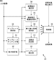
撮像部21は、例えば、CCD(Charge Coupled Device)ビデオカメラ等よりなり、撮像した画像を画像ディスプレイ25に表示させる。追尾対象検出部22は、撮像部21より入力された画像から追尾対象を検出し、検出結果をオブジェクト追尾部23に出力する。
The
オブジェクト追尾部23は、撮像部21より供給された画像中の、追尾対象検出部22により指定された追尾点を追尾するように動作する。またオブジェクト追尾部23は、追尾結果を追尾位置補正部24に出力するとともに、追尾結果に基づいて、移動したオブジェクトを撮像できるようにカメラ駆動部26を制御する。追尾位置補正部24は、指示入力部29を介してユーザから追尾位置の補正が指示された場合、オブジェクト追尾部23からの追尾結果にユーザからの補正値を反映し、その補正結果を画像ディスプレイ25に出力するとともに、オブジェクト追尾部23に補正結果を供給する。これにより、オブジェクト追尾部23は、補正された追尾点を次のフレームから追尾するように動作することができる。カメラ駆動部26は、オブジェクト追尾部23からの制御に基づいて、撮像部21が追尾点を中心とする画像を撮影するように撮像部21を駆動する。
The
制御部27は、例えば、マイクロコンピュータなどにより構成され、各部を制御する。また制御部27には、半導体メモリ、磁気ディスク、光ディスク、または光磁気ディスクなどにより構成されるリムーバブルメディア28が必要に応じて接続され、プログラム、その他各種のデータが必要に応じて供給される。指示入力部29は、各種のボタン、スイッチ、あるいは赤外線や電波を用いたリモートコントローラなどにより構成され、ユーザからの指示に対応する信号を制御部27に出力する。
The
次に、図2のフローチャートを参照して、図1に示した監視カメラシステムが実行する監視処理について説明する。この処理は、監視システム1の電源がオンされているとき、撮像部21により監視する領域が撮像され、その撮像して得られた画像が追尾対象検出部22およびオブジェクト追尾部23を介して画像ディスプレイ25に出力されて開始される。
Next, monitoring processing executed by the monitoring camera system shown in FIG. 1 will be described with reference to the flowchart of FIG. In this processing, when the power of the
ステップS1において、追尾対象検出部22は、撮像部21から入力された画像から追尾対象を検出する処理を実行する。例えば、入力画像に動く物体が存在する場合、追尾対象検出部22は、その動く物体を追尾対象として検出するとともに、追尾対象の中から、最も輝度の高い点あるいは追尾対象の中心の点などを追尾点として検出し、検出結果をオブジェクト追尾部23に出力する。なお、追尾対象は、ユーザが指示入力部29を介して所定の位置を指定して設定することももちろん可能である。
In step S <b> 1, the tracking
ステップS2において、オブジェクト追尾部23は、ステップS1の処理で検出された追尾点を追尾する追尾処理を実行する。追尾処理の詳細については、図5を参照して後述するが、この処理により、撮像部21により撮像された画像の中の追尾対象となるオブジェクト(例えば、人、動物など)の中の追尾点(例えば、目、頭の中心)が追尾され、追尾結果が制御部27に出力されるとともに、追尾位置を表す位置情報が追尾位置補正部24に出力される。
In step S2, the
ステップS3において、制御部27は、ステップS2の処理による追尾結果に基づいて、画像ディスプレイ25に、撮像部21により撮像された画像に追尾位置を表すマークなどを重畳して表示させる。
In step S3, the
ステップS4において、オブジェクト追尾部23は、ステップS2の処理による追尾結果に基づいて、オブジェクトの移動を検出し、移動したオブジェクトを撮像できるようにカメラを駆動させるカメラ駆動信号を生成し、カメラ駆動部26に出力する。ステップS5において、カメラ駆動部26は、オブジェクト追尾部23からのカメラ駆動信号に基づいて撮像部21を駆動する。これにより撮像部21は、追尾点が画面から外れてしまうことがないようにカメラをパンまたはチルトする。
In step S4, the
ステップS6において、制御部27は、指示入力部29を介したユーザからの指示に基づいて監視処理を終了するか否かを判定し、ユーザから終了が指示されていない場合には、ステップS1に戻り、それ以降の処理を繰り返し実行する。そして、ステップS6において、ユーザから監視処理の終了が指示されたと判定された場合、制御部27は監視処理を終了する。
In step S6, the
図3A乃至図3Cは、このとき画像ディスプレイ25に表示される画像の例を、時系列に示した図である。図3Aは、撮像部21により、追尾対象となるオブジェクト41が撮像された画像の例であり、この例では、図中左方向に走って移動する人が、オブジェクト41として撮像されている。図3Bでは、オブジェクト41が、図3Aの位置から図中左に移動しており、図3Cでは、オブジェクト41が、図3Bの位置からさらに左に移動している。
3A to 3C are diagrams showing examples of images displayed on the
追尾対象検出部22は、図2のステップS1で、オブジェクト41を検出し、このオブジェクト41である人の目を、追尾点41Aとしてオブジェクト追尾部23に出力する。ステップS2ではオブジェクト追尾部23により追尾処理が行われる。
The tracking
次に、図1のオブジェクト追尾部23の詳細な構成例と、その動作について説明する。
Next, a detailed configuration example and operation of the
図4は、オブジェクト追尾部23の機能的構成例を示すブロック図である。図4に示されるように、オブジェクト追尾部23は、テンプレートマッチング部51、動き推定部52、シーンチェンジ検出部53、背景動き推定部54、領域推定関連処理部55、乗り換え候補保持部56、追尾点決定部57、テンプレート保持部58、および制御部59により構成されている。
FIG. 4 is a block diagram illustrating a functional configuration example of the
テンプレートマッチング部51は、入力画像と、テンプレート保持部58に保持されているテンプレート画像のマッチング処理を行う。動き推定部52は、入力画像の動きを推定し、推定の結果得られた動きベクトルと、その動きベクトルの確度を、シーンチェンジ検出部53、背景動き推定部54、領域推定関連処理部55、および追尾点決定部57に出力する。シーンチェンジ検出部53は、動き推定部52より供給された動きベクトルとその動きベクトルの確度に基づいて、シーンチェンジを検出する。
The
背景動き推定部54は、動き推定部52より供給された動きベクトルとその動きベクトルの確度に基づいて背景動きを推定する処理を実行し、推定結果を領域推定関連処理部55に供給する。領域推定関連処理部55は、動き推定部52より供給された動きベクトルとその動きベクトルの確度、背景動き推定部54より供給された背景動き、並びに追尾点決定部57より供給された追尾点情報に基づいて、領域推定処理を行う。また領域推定関連処理部55は、入力された情報に基づいて乗り換え候補を生成し、乗り換え候補保持部56へ供給し、保持させる。さらに領域推定関連処理部55は、入力画像に基づいてテンプレートを作成し、テンプレート保持部58に供給し、保持させる。
The background
追尾点決定部57は、動き推定部52より供給された動きベクトルとその動きベクトルの確度、および乗り換え候補保持部56より供給された乗り換え候補に基づいて、追尾点を決定し、決定された追尾点に関する情報を領域推定関連処理部55に出力する。
The tracking
制御部59は、追尾対象検出部22から出力された追尾点の情報に基づいて、テンプレートマッチング部51乃至テンプレート保持部58の各部を制御して、検出された追尾対象を追尾させるとともに、画像ディスプレイ25に表示される画面の中に、追尾点が表示されるようにカメラ駆動部26に制御信号を出力し、撮像部21の駆動を制御する。これにより、追尾点が画面の外に出ないように制御される。また制御部59は、追尾点の画面上での位置の情報などの追尾結果を、追尾位置補正部24および制御部27などに出力する。
The
次に、オブジェクト追尾部23の動作について説明する。
Next, the operation of the
図5は、図2のステップS2におけるオブジェクト追尾部23が実行する追尾処理の詳細を説明するフローチャートである。
FIG. 5 is a flowchart illustrating details of the tracking process executed by the
図5に示されるように、オブジェクト追尾部23は、基本的に通常処理と例外処理を実行する。すなわち、ステップS11で通常処理が行われる。この通常処理の詳細は、図9のフローチャートを参照して後述するが、この処理により追尾対象検出部22により検出された追尾点を追尾する処理が実行される。
As shown in FIG. 5, the
ステップS11の通常処理において追尾点の追尾ができなくなったとき、ステップS12において、例外処理が実行される。この例外処理の詳細は、図12のフローチャートを参照して後述するが、この例外処理により、追尾点が画像から見えなくなったとき、テンプレートマッチングにより通常処理への復帰処理が実行される。例外処理によって追尾処理を継続することができなくなった、すなわち、通常処理へ復帰することができなくなったと判定された場合には処理が終了されるが、テンプレートマッチングによる復帰処理の結果、通常処理への復帰が可能と判定された場合には、処理は再びステップS11に戻る。このようにして、ステップS11の通常処理とステップS12の例外処理が、各フレーム毎に順次繰り返し実行される。 When the tracking point cannot be tracked in the normal process of step S11, an exception process is executed in step S12. Details of this exception processing will be described later with reference to the flowchart of FIG. 12. When the tracking point is not visible from the image by this exception processing, a return processing to the normal processing is executed by template matching. If it is determined that the tracking process cannot be continued due to the exception process, that is, the process cannot be returned to the normal process, the process is terminated. If it is determined that it is possible to return, the process returns to step S11 again. In this manner, the normal process in step S11 and the exception process in step S12 are repeatedly executed sequentially for each frame.
本実施の形態においては、この通常処理と例外処理により、図6乃至図8に示されるように、追尾対象が回転したり、オクルージョンが発生したり、シーンチェンジが発生する等、追尾点が一時的に見えなくなった場合においても、追尾が可能となる。 In the present embodiment, as shown in FIGS. 6 to 8, the tracking point is temporarily changed by the normal process and the exception process, such as the tracking target rotating, the occlusion occurring, the scene changing, etc. Tracking is possible even if it becomes invisible.
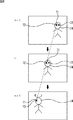
図6の例では、フレームn−1において、追尾対象としての人の顔74が表示されており、この人の顔74は、右目72と左目73を有している。ユーザが、このうちの、例えば右目72(正確には、その中の1つの画素)を追尾点71として指定したとする。図6の例においては、次のフレームnにおいて、追尾対象としての人が図中左方向に移動しており、さらに次のフレームn+1においては、人の顔74が時計方向に回動している。その結果、今まで見えていた右目72が表示されなくなり、追尾ができなくなる。そこで、上述した図5のステップS11の通常処理においては、右目72と同一の対象物としての顔74上の左目73が新たな追尾点として選択され、追尾点が左目73に乗り換えられる。これにより追尾が可能となる。
In the example of FIG. 6, a person's
図7の例では、フレームn−1において、追尾対象としての人の顔74の図中左側からボール81が移動してきており、次のフレームnにおいて、ボール81がちょうど顔74を覆う状態となっている。この状態においては、追尾点71として指定されていた右目72を含む顔74が表示されていない。このようなオクルージョンが起きると、対象物としての顔74が表示されていないので、追尾点71に代えて追尾する乗り換え点もなくなり、以後、追尾点を追尾することが困難になる。そこで本実施の形態においては、追尾点71としての右目72を含むフレームn−1(実際には時間的にもっと前のフレーム)の画像がテンプレートとして予め保存され、ボール81がさらに右側に移動し、フレームn+1において、追尾点71として指定された右目72が再び現れると、上述した図5のステップS12の例外処理により、追尾点71としての右目72が再び表示されたことがテンプレートに基づいて確認され、右目72が再び追尾点71として追尾されることになる。
In the example of FIG. 7, the
図8の例では、フレームn−1において、追尾対象としての人の顔74が表示されているが、次のフレームnにおいて、自動車91が人の顔74を含む全体を覆い隠している。すなわち、この場合、シーンチェンジが起きたことになる。そこで本実施の形態においては、このようにシーンチェンジが起きて追尾点71が画像から存在しなくなっても、自動車91が移動して、フレームn+1において再び右目72が表示されると、上述した図5のステップS12の例外処理により、追尾点71としての右目72が再び出現したことがテンプレートに基づいて確認され、この右目72を再び追尾点71として追尾することが可能となる。
In the example of FIG. 8, the person's
次に、図9のフローチャートを参照して、図5のステップS11の通常処理の詳細について説明する。 Next, the details of the normal processing in step S11 in FIG. 5 will be described with reference to the flowchart in FIG.
ステップS21において、追尾点決定部57は、通常処理の初期化処理を実行する。その詳細は、図10のフローチャートを参照して後述するが、この処理によりユーザから追尾するように指定された追尾点を基準とする領域推定範囲が設定される。この領域推定範囲は、ユーザにより指定された追尾点と同一の対象物(例えば、追尾点が人の目である場合、目と同様の動きをする剛体としての人の顔、または人の体など)に属する点の範囲を推定する際に参照する範囲である。乗り換え点は、この領域推定範囲の中の点から選択される。
In step S21, the tracking
ステップS22において、制御部59は、次のフレームの画像の入力を待機するように各部を制御する。ステップS23において、動き推定部52は、追尾点の動きを推定する。すなわち、ユーザにより指定された追尾点を含むフレーム(ここでは前フレームという)より時間的に後のフレーム(ここでは後フレームという)をステップS22の処理で取り込むことで、結局連続する2フレームの画像が得られたことになるので、ステップS23において、前フレームの追尾点に対応する後フレームの追尾点の位置を推定することで、追尾点の動きが推定される。
In step S22, the
なお、時間的に前または後とは、入力の順番や処理の順番をいう。通常、撮像の順番に各フレームの画像が入力されるので、その場合、より時間的に前に撮像されたフレームが前フレームとなるが、時間的に後に撮像されたフレームが先に処理される場合には、時間的に後に撮像されたフレームが前フレームとなる。 Note that “before or after in time” means the order of input or the order of processing. Usually, since the images of each frame are input in the order of imaging, in that case, the frame captured earlier in time becomes the previous frame, but the frame captured later in time is processed first. In this case, a frame that is imaged later in time becomes the previous frame.
ステップS24において、動き推定部52は、ステップS23の処理の結果、追尾点が推定可能であったか否かを判定する。追尾点が推定可能であったか否かは、例えば、動き推定部52が生成、出力する動きベクトル(後述)の確度の値を、予め設定されている閾値と比較することで判定される。具体的には、動きベクトルの確度が閾値以上であれば推定が可能であり、閾値より小さければ推定が不可能であると判定される。すなわち、ここにおける可能性は比較的厳格に判定され、実際には推定が不可能ではなくても確度が低い場合には、不可能と判定される。これにより、より確実な追尾処理が可能となる。
In step S24, the
なお、ステップS24では、追尾点での動き推定結果と追尾点の近傍の点での動き推定結果が、多数を占める動きと一致する場合には推定可能、一致しない場合には推定不可能と判定するようにすることも可能である。 In step S24, it is determined that the motion estimation result at the tracking point and the motion estimation result at a point in the vicinity of the tracking point can be estimated if the motion occupies a large number of motions. It is also possible to do so.
ステップS24において、追尾点の動きが推定可能であると判定された場合、つまり、追尾点が同一対象物上の対応する点上に正しく設定されている確率が比較的高い場合、ステップS25に進む。より具体的には、図6の例において右目72が追尾点71として指定された場合、右目72が正しく追尾されている確率が比較的高い場合には追尾点の動きが推定可能であると判定される。
If it is determined in step S24 that the movement of the tracking point can be estimated, that is, if the probability that the tracking point is correctly set on the corresponding point on the same object is relatively high, the process proceeds to step S25. . More specifically, when the
ステップS25において、追尾点決定部57は、ステップS23の処理で得られた推定動き(いわゆる動きベクトル)の分だけ追尾点をシフトする。これにより、前フレームの追尾点の追尾後の後フレームにおける追尾の位置が決定されることになる。
In step S25, the tracking
ステップS25の処理の後、ステップS26において、領域推定関連処理が実行される。この領域推定関連処理の詳細は、本出願人が先に提案している特開2005−303983号公報に開示されている。この処理により、ステップS21の通常処理の初期化処理で指定された領域推定範囲が更新される。また対象物体が回転するなどして、追尾点が表示されない状態になった場合に、追尾点を乗り換えるべき点としての乗り換え点としての候補(乗り換え候補)が、まだ追尾が可能な状態において予め抽出され、乗り換え候補保持部56で保持される。さらに乗り換え候補への乗り換えもできなくなった場合、追尾は一旦中断されるが、追尾点が再び出現することで再び追尾が可能になったことを確認するためのテンプレートが予め作成され、テンプレート保持部58で保持される。
After step S25, region estimation related processing is executed in step S26. Details of this region estimation related processing are disclosed in Japanese Patent Laid-Open No. 2005-303983 previously proposed by the present applicant. With this process, the area estimation range designated in the initialization process of the normal process in step S21 is updated. In addition, when the tracking point is not displayed due to rotation of the target object, candidates for transfer points (transfer candidates) as points to be transferred are previously extracted in a state where tracking is still possible. And is held by the transfer
ステップS26の領域推定関連処理が終了した後、処理は再びステップS22に戻り、それ以降の処理が繰り返し実行される。 After the region estimation related processing in step S26 is completed, the processing returns to step S22 again, and the subsequent processing is repeatedly executed.
このように、ユーザから指定された追尾点の動きが推定可能である限り、ステップS22乃至ステップS26の処理がフレーム毎に繰り返し実行され、追尾が行われることになる。 As described above, as long as the movement of the tracking point designated by the user can be estimated, the processing from step S22 to step S26 is repeatedly executed for each frame, and tracking is performed.
これに対して、ステップS24において、追尾点の動きが推定不可能であると判定された場合、すなわち、上述したように、例えば動きベクトルの確度が閾値以下であるような場合には、処理はステップS27に進む。 On the other hand, when it is determined in step S24 that the movement of the tracking point cannot be estimated, that is, as described above, for example, when the accuracy of the motion vector is equal to or less than the threshold value, the processing is performed. Proceed to step S27.
ステップS27において、追尾点決定部57は、ステップS26の領域推定関連処理で生成された乗り換え候補が乗り換え候補保持部56に保持されているので、その中から、元の追尾点に最も近い乗り換え候補を1つ選択する。追尾点決定部57は、ステップS28で乗り換え候補が選択できたか否かを判定し、乗り換え候補が選択できた場合には、ステップS29に進み、追尾点をステップS27の処理で選択した乗り換え候補に乗り換える(変更する)。これにより、乗り換え候補の点が新たな追尾点として設定される。
In step S27, the tracking
ステップS29の処理の後、処理はステップS23に戻り、乗り換え候補の中から選ばれた追尾点の動きを推定する処理が実行される。そして、ステップS24において新たに設定された追尾点の動きが推定可能であるか否かが再び判定され、推定可能であれば、ステップS25において追尾点を推定動き分だけシフトする処理が行われ、ステップS26において領域推定関連処理が実行される。その後、処理は再びステップS22に戻り、それ以降の処理が繰り返し実行される。 After the process of step S29, the process returns to step S23, and the process of estimating the movement of the tracking point selected from the transfer candidates is executed. Then, it is determined again whether or not the motion of the newly set tracking point can be estimated in step S24. If it can be estimated, a process of shifting the tracking point by the estimated motion is performed in step S25. In step S26, region estimation related processing is executed. Thereafter, the process returns to step S22 again, and the subsequent processes are repeatedly executed.
ステップS24において、新たに設定された追尾点も推定不可能であると判定された場合には、再びステップS27に進み、乗り換え候補の中から、元の追尾点に次に最も近い乗り換え候補が選択され、ステップS29において、その乗り換え候補が新たな追尾点として設定される。その新たな追尾点について、再びステップS23以降の処理が繰り返される。 If it is determined in step S24 that the newly set tracking point cannot be estimated, the process proceeds again to step S27, and the next transfer candidate closest to the original tracking point is selected from the transfer candidates. In step S29, the transfer candidate is set as a new tracking point. The process after step S23 is repeated again for the new tracking point.
乗り換え候補保持部56で保持されているすべての乗り換え候補を新たな追尾点としても、追尾点の動きを推定することができなかった場合には、ステップS28において、乗り換え候補が選択できなかったと判定され、この通常処理は終了される。そして、図5のステップS12の例外処理に処理が進むことになる。
Even if all the transfer candidates held in the transfer
次に、図10のフローチャートを参照して、図9のステップS21の通常処理の初期化処理の詳細について説明する。 Next, details of the initialization process of the normal process in step S21 of FIG. 9 will be described with reference to the flowchart of FIG.
ステップS41において、制御部59は、今の処理は例外処理からの復帰の処理であるか否かを判定する。すなわち、図5のステップS12の例外処理を終了した後、再びステップS11の通常処理に戻ってきたのか否かが判定される。最初のフレームの処理においては、まだステップS12の例外処理は実行されていないので、例外処理からの復帰ではないと判定され、処理はステップS42に進む。
In step S41, the
ステップS42において、追尾点決定部57は、追尾点を追尾点指示の位置に設定する処理を実行する。すなわち、入力画像の中で、例えば、最も輝度の高い点が追尾点として設定される。
In step S42, the tracking
なお、追尾点は、ユーザによる指定など、他の方法により設定されるようにしてもよい。ユーザによる指定とは、例えば、ユーザが指示入力部29を操作することで、制御部59に対して、入力画像の中の所定の点を追尾点として指定することにより行われることである。追尾点決定部57は、設定した追尾点の情報を領域推定関連処理部55に供給する。
The tracking point may be set by other methods such as designation by the user. The designation by the user is, for example, performed by designating a predetermined point in the input image as a tracking point to the
ステップS43において、領域推定関連処理部55は、ステップS42の処理で設定された追尾点の位置情報に基づき、領域推定範囲を設定する。この領域推定範囲は、追尾点と同じ剛体上の点を推定する際の参照範囲であり、予め追尾点と同じ剛体部分が領域推定範囲の大部分を占めるように、より具体的には、追尾点と同じ剛体部分に推定領域範囲の位置や大きさが追随するように設定することで、領域推定範囲の中で最も多数を占める動きを示す部分を追尾点と同じ剛体部分であると推定できるようにするためのものである。ステップS43では、初期値として、例えば、追尾点を中心とする予め設定された一定の範囲が領域推定範囲とされる。その後、処理は図9のステップS22に進むことになる。
In step S43, the region estimation related processing
一方、ステップS41において、現在の処理が、図5のステップS12の例外処理からの復帰の処理であると判定された場合、ステップS44に進む。ステップS44において、追尾点決定部57は、図12のフローチャートを参照して後述する例外処理によるテンプレートにマッチした位置に基づき追尾点と領域推定範囲を設定する。例えば、テンプレート上の追尾点とマッチした現フレーム上の点が追尾点とされ、その点から予め設定されている一定の範囲が領域推定範囲とされる。その後、処理は図9のステップS22に進む。
On the other hand, if it is determined in step S41 that the current process is a return process from the exception process in step S12 of FIG. 5, the process proceeds to step S44. In step S44, the tracking
以上の処理を、図11を参照して説明すると次のようになる。 The above process will be described with reference to FIG.
図10のステップS42において、例えば、図11に示されるように、フレームn−1の人の右目72が追尾点71として指定されると、ステップS43において、追尾点71を含む所定の領域が領域推定範囲101として指定される。図9のステップS24において、領域推定範囲101の範囲内のサンプル点が次のフレームにおいて推定可能であるか否かが判定される。図11の例の場合、フレームnの次のフレームn+1においては、領域推定範囲101のうち、右目72を含む図中左側半分の領域102がボール81で隠されているため、フレームnの追尾点71の動きを、次のフレームn+1において推定することができない。そこで、このような場合においては、時間的に前のフレームn−1で乗り換え候補として予め用意されていた領域指定範囲101内(右目72を含む剛体として
の顔74内)の点の中から1つの点(例えば、顔74に含まれる左目73(正確には、その中の1つの画素))が選択され、その点がフレームn+1における、新たな追尾点とされる。
In step S42 of FIG. 10, for example, as shown in FIG. 11, when the
次に、図12のフローチャートを参照して、図5のステップS11の通常処理に続いて行われる、ステップS12の例外処理の詳細について説明する。この処理は、上述したように、図9のステップS24において追尾点の動きを推定することが不可能と判定され、さらにステップS28において追尾点を乗り換える乗り換え候補が選択できなかったと判定された場合に実行されることになる。 Next, with reference to the flowchart of FIG. 12, the details of the exception process of step S12 performed following the normal process of step S11 of FIG. 5 will be described. As described above, this process is performed when it is determined in step S24 in FIG. 9 that it is impossible to estimate the movement of the tracking point, and in step S28, it is determined that the transfer candidate for changing the tracking point cannot be selected. Will be executed.
ステップS51において、制御部59は、例外処理の初期化処理を実行する。ここで、図13のフローチャートを参照して、例外処理の初期化処理の詳細について説明する。
In step S51, the
ステップS61において、制御部59は、追尾点の動きを推定することが不可能で、かつ、追尾点を乗り換える乗り換え候補が選択できなかった際にシーンチェンジが起きていたか否かを判定する。シーンチェンジ検出部53は、動き推定部52の推定結果に基づいてシーンチェンジがあったか否かを常に監視しており、制御部59は、そのシーンチェンジ検出部53の検出結果に基づいて、ステップS61の判定処理を実行する。シーンチェンジ検出部53の具体的処理については、図24と図25を参照して後述する。
In step S61, the
シーンチェンジが起きている場合、制御部59は、追尾ができなくなった理由がシーンチェンジが発生したことによるものと推定して、ステップS62においてモードをシーンチェンジに設定する。これに対して、ステップS61においてシーンチェンジが発生していないと判定された場合には、制御部59は、ステップS63においてモードをその他のモードに設定する。
If a scene change has occurred, the
ステップS62またはステップS63の処理の後、ステップS64においてテンプレートマッチング部51は、時間的に最も古いテンプレートを選択する処理を実行する。具体的には、図14に示されるように、例えばフレームnからフレームn+1に移行するとき、例外処理が実行されるものとすると、フレームn−m+1からフレームnに関して生成され、テンプレート保持部58に保持されているm個のフレームのテンプレートの中から、時間的に最も古いテンプレートであるフレームn−m+1に関して生成されたテンプレートが選択される。
After the process of step S62 or step S63, the
このように例外処理への移行直前のテンプレート(図14の例の場合フレームnに関して生成されたテンプレート)を用いずに、時間的に少し前のテンプレートを選択するのは、次のような理由からである。つまり、追尾対象のオクルージョンなどで例外処理への移行が発生した場合には、移行の直前には追尾対象が既にかなり隠れており、その時点のテンプレートでは、追尾対象を充分に大きく捉えることができない可能性が高いからである。従って、このように時間的に若干前のフレームにおけるテンプレートを選択することで、確実な追尾が可能となる。 In this way, the template immediately before the transition to exception processing (the template generated with respect to frame n in the case of the example in FIG. 14) is not used, and the template slightly before in time is selected for the following reason. It is. In other words, if a transition to exception processing occurs due to the tracking target occlusion, the tracking target is already quite hidden immediately before the transition, and the tracking target cannot be captured sufficiently large in the template at that time. This is because the possibility is high. Therefore, reliable tracking is possible by selecting a template in a frame slightly before in time.
図13の説明に戻る。ステップS65において、テンプレートマッチング部51は、テンプレート探索範囲を設定する処理を実行する。テンプレート探索範囲は、例えば、例外処理に移行する直前の追尾点の位置がテンプレート探索範囲の中心となるように設定される。
Returning to the description of FIG. In step S65, the
すなわち、図15に示されるように、フレームnにおいて被写体の顔74の右目72が追尾点71として指定されている場合において、図中左方向からボール81が飛んできて、フレームn+1において追尾点71を含む顔74が隠れ、フレームn+2において、再び追尾点71が現れる場合を想定する。この場合において、テンプレート範囲111に含まれる追尾点71を中心とする領域がテンプレート探索範囲112として設定される。
That is, as shown in FIG. 15, when the
ステップS66において、テンプレートマッチング部51は、例外処理への移行後の経過フレーム数およびシーンチェンジ数を0にリセットする。このフレーム数とシーンチェンジ数は、後述する図12のステップS55における継続判定処理(図16のステップS71,S73,S75,S77)において使用される。
In step S66, the
以上のようにして、例外処理の初期化処理が終了した後、図12のステップS52において、制御部59は次のフレームの画像の入力を待機する処理を実行する。ステップS53において、テンプレートマッチング部51は、テンプレート探索範囲内においてテンプレートマッチング処理を行う。
After the exception process initialization process is completed as described above, in step S52 of FIG. 12, the
ステップS54においてテンプレートマッチング部51は、通常処理への復帰が可能であるか否かを判定する。すなわち、テンプレートマッチング処理により、数フレーム前のテンプレート(図15のテンプレート範囲111内の画素)と、テンプレート探索範囲内のマッチング対象の画素の差分の絶対値和が演算される。
In step S54, the
より詳細には、テンプレート範囲111内の所定のブロックと、テンプレート探索範囲内の所定のブロックにおけるそれぞれの画素の差分の絶対値和が演算される。ブロックの位置がテンプレート範囲111内で順次移動され、各ブロックの差分の絶対値和が加算され、そのテンプレートの位置における値とされる。そして、テンプレートをテンプレート探索範囲内で順次移動させた場合における差分の絶対値和が最も小さくなる位置とその値が検索される。ステップS54において、検索された最小の差分の絶対値和が、予め設定されている所定の閾値と比較される。差分の絶対値和が閾値以下である場合には、テンプレートに含まれている追尾点を含む画像が再び出現したことになるので、通常処理への復帰が可能であると判定され、処理は図5のステップS11の通常処理に戻る。
More specifically, the absolute value sum of the difference between each pixel in the predetermined block in the
そして、上述したように、図10のステップS41において、例外処理からの復帰であると判定され、ステップS44において、差分絶対値和が最小となる位置をテンプレートのマッチした位置として、このマッチした位置とテンプレートに対応して保持してあったテンプレート位置と追尾点領域推定範囲の位置関係から、追尾点と領域推定範囲の設定が行われる。 Then, as described above, in step S41 of FIG. 10, it is determined that the process returns from the exception process. In step S44, the position where the sum of absolute differences is minimum is set as the matched position of the template. The tracking point and the area estimation range are set based on the positional relationship between the template position held corresponding to the template and the tracking point area estimation range.
図12のステップS54における通常処理への復帰が可能であるか否かの判定は、最小の差分絶対値和をテンプレートのアクティビティで除算して得られる値を閾値と比較することで行うようにしてもよい。この場合におけるアクティビティは、後述する図17のアクティビティ算出部122により、図18のステップS93において算出された値を用いることができる。
In step S54 of FIG. 12, it is determined whether or not it is possible to return to normal processing by comparing the value obtained by dividing the minimum sum of absolute differences by the activity of the template with a threshold value. Also good. As the activity in this case, the value calculated in step S93 in FIG. 18 by the
あるいはまた、今回の最小の差分絶対値和を1フレーム前における最小の差分絶対値和で除算することで得られた値を所定の閾値と比較することで、通常処理への復帰が可能であるか否かを判定するようにしてもよい。この場合、アクティビティの計算が不要となる。すなわち、ステップS54では、テンプレートとテンプレート探索範囲の相関が演算され、相関値と閾値の比較に基づいて判定が行われる。 Alternatively, it is possible to return to the normal processing by comparing a value obtained by dividing the current minimum absolute difference sum by the minimum absolute difference sum one frame before with a predetermined threshold. It may be determined whether or not. In this case, it is not necessary to calculate the activity. That is, in step S54, the correlation between the template and the template search range is calculated, and determination is performed based on the comparison between the correlation value and the threshold value.
ステップS54において、通常処理への復帰が可能ではないと判定された場合、ステップS55に進み、継続判定処理が実行される。継続判定処理の詳細は、図16のフローチャートを参照して後述するが、この処理により、例外処理が継続可能であるか否かの判定が行われる。 If it is determined in step S54 that it is not possible to return to the normal process, the process proceeds to step S55, and the continuation determination process is executed. The details of the continuation determination process will be described later with reference to the flowchart of FIG. 16, and this process determines whether or not the exception process can be continued.
ステップS56において、制御部59は、ステップS55の継続判定処理による例外処理での追尾点の追尾が継続可能であるか否かの継続判定結果に基づいて(後述する図16のステップS76,S78で設定されたフラグに基づいて)判定する。例外処理での追尾点の追尾処理が継続可能であると判定された場合、処理はステップS52に戻り、それ以降の処理が繰り返し実行される。すなわち、追尾点が再び出現するまで待機する処理が繰り返し実行される。
In step S56, the
これに対して、ステップS56において、例外処理での追尾点の追尾処理が継続可能ではないと判定された場合(後述する図16のステップS75の処理で追尾点が消失した後の経過フレーム数が閾値THfr以上と判定されるか、または、ステップS77の処理でシーンチェンジ数が閾値THsc以上と判定された場合)、もはや例外処理は不可能であるとして、追尾処理は終了される。なお、追尾処理を終了するのではなく、保持しておいた追尾点を用いて再度通常処理に戻るようにすることも考えられる。この場合の処理については、図36のフローチャートを参照して後述する。 On the other hand, when it is determined in step S56 that the tracking process of the tracking point in the exception process cannot be continued (the number of elapsed frames after the tracking point disappears in the process of step S75 in FIG. 16 described later). If it is determined that the threshold value THfr or more is determined or the number of scene changes is determined to be greater than or equal to the threshold value THsc in the process of step S77), it is determined that exception processing is no longer possible, and the tracking process is terminated. Instead of ending the tracking process, it may be possible to return to the normal process again using the tracking point that has been held. The processing in this case will be described later with reference to the flowchart of FIG.
次に、図16のフローチャートを参照して、図12のステップS55における継続判定処理の詳細について説明する。 Next, details of the continuation determination process in step S55 of FIG. 12 will be described with reference to the flowchart of FIG.
ステップS71において、制御部59は、変数としての経過フレーム数に1を加算する処理を実行する。経過フレーム数は、図12のステップS51の例外処理の初期化処理(図13のステップS66)において、予め0にリセットされている。
In step S71, the
次にステップS72において、制御部59は、シーンチェンジがあるか否かを判定する。シーンチェンジがあるか否かは、シーンチェンジ検出部53が、常にその検出処理を実行しており、その検出結果に基づいて判定が可能である。シーンチェンジがあると判定された場合にはステップS73に進み、制御部59は、変数としてのシーンチェンジ数に1を加算する。このシーンチェンジ数も、図13のステップS66の初期化処理において0にリセットされている。通常処理から例外処理への移行時にシーンチェンジが発生していないと判定された場合には、ステップS73の処理はスキップされる。
Next, in step S72, the
次に、ステップS74において、制御部59は、現在設定されているモードがシーンチェンジであるか否かを判定する。このモードは、図13のステップS62またはS63において設定されたものである。現在設定されているモードがシーンチェンジであると判定された場合にはステップS77に進み、制御部59は、シーンチェンジ数が予め設定されている閾値THscより小さいか否かを判定する。制御部59は、ステップS77において、シーンチェンジ数が閾値THscより小さいと判定した場合にはステップS76に進み、継続可のフラグを設定し、シーンチェンジ数が閾値THsc以上であると判定した場合にはステップS78に進み、継続不可のフラグを設定する。
Next, in step S74, the
一方、ステップS74において、モードがシーンチェンジではないと判定された場合(モードがその他であると判定された場合)、ステップS75に進み、制御部59は、経過フレーム数が閾値THfrより小さいか否かを判定する。この経過フレーム数も、図13の例外処理の初期化処理のステップS66において、予め0にリセットされている。制御部59は、ステップS75において、経過フレーム数が閾値THfrより小さいと判定された場合にはステップS76に進み、継続可のフラグを設定し、経過フレーム数が閾値THfr以上であると判定された場合にはステップS78に進み、継続不可のフラグを設定する。
On the other hand, when it is determined in step S74 that the mode is not a scene change (when it is determined that the mode is other), the process proceeds to step S75, and the
このように、テンプレートマッチング処理時におけるシーンチェンジ数が閾値THsc以上になるか、または経過フレーム数が閾値THfr以上になった場合には、それ以上の例外処理は不可能とされる。 As described above, when the number of scene changes at the time of template matching processing is equal to or greater than the threshold value THsc, or when the number of elapsed frames is equal to or greater than the threshold value THfr, further exception processing is impossible.
なお、モードがその他である場合には、シーンチェンジ数が0であるという条件も加えて、継続が可能であるか否かを判定するようにしてもよい。 When the mode is other, a condition that the number of scene changes is 0 may be added to determine whether or not continuation is possible.
以上においては、画像のフレームを処理単位とし、すべてのフレームを用いることを前提としたが、フィールド単位で処理したり、すべてのフレームまたはフィールドを利用するのではなく、所定の間隔で間引いて抽出されたフレームまたはフィールドを用いるようにすることも可能である。 In the above, it is assumed that the frame of the image is used as a processing unit and all frames are used. However, processing is not performed in units of fields or using all frames or fields, but is extracted by thinning out at a predetermined interval. It is also possible to use a modified frame or field.
次に、図17を参照して、図4の動き推定部52の構成例について説明する。図17に示されるように、評価値算出部121、アクティビティ算出部122、および動きベクトル検出部123には、入力画像が供給されている。
Next, a configuration example of the
評価値算出部121は、動きベクトルにより対応付けられる両対象の一致度に関する評価値を算出し、正規化処理部125に供給する。アクティビティ算出部122は、入力画像のアクティビティを算出し、閾値判定部124と正規化処理部125に供給する。動きベクトル検出部123は、入力画像から動きベクトルを検出し、評価値算出部121と統合処理部126に供給する。
The evaluation
閾値判定部124は、アクティビティ算出部122より供給されたアクティビティを所定の閾値と比較し、その判定結果を統合処理部126に供給する。正規化処理部125は、評価値算出部121より供給された評価値を、アクティビティ算出部122より供給されたアクティビティに基づいて正規化し、得られた値を統合処理部126に供給する。
The
統合処理部126は、正規化処理部125から供給された正規化情報と、閾値判定部124より供給された判定結果に基づいて、動きベクトルの確度を演算し、得られた確度を動きベクトル検出部123より供給された動きベクトルとともに出力する。
The
次に、図18のフローチャートを参照して、動き推定部52が実行する動き推定処理について説明する。動きベクトルは、点に対するものとして求められているが、その確度は、動きベクトルにより対応付けられる2つの点の近傍の、例えば点を中心とする、小ブロックの画像データを用いて計算される。
Next, a motion estimation process executed by the
ステップS91において、動きベクトル検出部123は、入力画像から動きベクトルを検出する。この検出には、例えばブロックマッチング方式や勾配法が用いられる。検出された動きベクトルは、評価値算出部121と統合処理部126に供給される。
In step S91, the motion
ステップS92において、評価値算出部121は、ステップS91の処理で検出された動きベクトルにより対応付けられる両対象の一致度に関する評価値を算出する。具体的には、例えば、動きベクトルで対応付けられる2つの点を中心とする2つのブロックの画素値の差分絶対値和が算出される。すなわち、ステップS91の処理で動きベクトル検出部123により検出された動きベクトルV(vx,vy)と、それに基づく時間的に前のフレームの画像Fi上の点P(Xp,Yp)、並びに時間的に後のフレームの画像Fj上の点Q(Xq,Yq)の関係は次式(1)で表される。
In step S92, the evaluation
![]()
![]()
評価値算出部121は点Pを中心とするブロックと、点Qを中心とするブロックについて、次式(2)に基づいて評価値Eval(P,Q,i,j)を演算する。
The evaluation

各ブロックは、1辺が2L+1画素の正方形とされている。上記式(2)における総和ΣΣは、xが−LからLについて、yが−LからLについて、対応する画素同士で行われる。従って、例えば、L=2である場合、9個の差分が得られ、その絶対値の総和が演算される。評価値は、その値が0に近づくほど、2つのブロックがよく一致していることを表している。 Each block is a square having 2L + 1 pixels on one side. The sum ΣΣ in the above equation (2) is performed between corresponding pixels when x is from −L to L and y is from −L to L. Therefore, for example, when L = 2, nine differences are obtained, and the sum of the absolute values is calculated. The evaluation value indicates that the two blocks match well as the value approaches zero.
評価値算出部121は、算出した評価値を正規化処理部125に供給する。
The evaluation
ステップS93において、アクティビティ算出部122は、入力画像からアクティビティを算出する。アクティビティは、画像の複雑さを表す特徴量であり、図19に示されるように、各画素毎に注目画素Y(x,y)と、それに隣接する8画素Y(x+i,y+j)との差分絶対値和の平均値が、注目画素位置のアクティビティActivity(x,y)として次式(3)に基づいて演算される。
In step S93, the
図19の例の場合、3×3画素のうち、中央に位置する注目画素Y(x,y)の値は110であり、それに隣接する8個の画素の値は、それぞれ80,70,75,100,100,100,80,80であるから、アクティビティActivity(x,y)は次式で表される。 In the case of the example in FIG. 19, the value of the pixel of interest Y (x, y) located in the center among 3 × 3 pixels is 110, and the values of eight pixels adjacent to it are 80, 70, and 75, respectively. , 100, 100, 100, 80, 80, the activity Activity (x, y) is expressed by the following equation.
Activity(x,y) ={|80−110|+|70−110|+|75−110|+|100−110|+|100−110|+|100−110|+|80−110|+|80−110|}/8 =24.375となる。 Activity (x, y) = {| 80-110 | + | 70-110 | + | 75-110 | + | 100-110 | + | 100-110 | + | 80-110 | + | 80−110 |} /8=24.375.
同様の処理が、そのフレームのすべての画素について実行される。 Similar processing is performed for all pixels in the frame.
ブロック単位で動きベクトル確度を算出するため、次式(4)で表されるブロック内の全画素のアクティビティの総和が、そのブロックのアクティビティ(ブロックアクティビティ)Blockactivity(i,j)と定義される。 In order to calculate the motion vector accuracy in units of blocks, the sum of the activities of all the pixels in the block expressed by the following equation (4) is defined as the activity (block activity) Blockactivity (i, j) of the block.
![]()
![]()
なお、アクティビティとしては、この他、分散値、ダイナミックレンジなどとすることも可能である。 In addition, the activity may be a variance value, a dynamic range, or the like.
ステップS94において、閾値判定部124は、ステップS93の処理で算出されたブロックアクティビティを予め設定されている所定の閾値と比較する。そして、入力されたブロックアクティビティが閾値より大きいか否かを表すフラグを統合処理部126に出力する。
In step S94, the
具体的には、実験の結果、ブロックアクティビティと評価値は、動きベクトルをパラメータとして、図20に示される関係を有する。図20において、横軸はブロックアクティビティBlockactivity(i,j)を表し、縦軸は評価値Evalを表している。 Specifically, as a result of the experiment, the block activity and the evaluation value have the relationship shown in FIG. 20 with the motion vector as a parameter. In FIG. 20, the horizontal axis represents the block activity Blockactivity (i, j), and the vertical axis represents the evaluation value Eval.
動きが正しく検出されている場合(正しい動きベクトルが与えられている場合)、そのブロックアクティビティと評価値の値は、曲線131より図中下側の領域R1に分布する。これに対して誤った動き(不正解の動きベクトル)が与えられた場合、そのブロックアクティビティと評価値の値は、曲線132より、図中左側の領域R2に分布する。なお、曲線132より上側の領域R2以外の領域と曲線131より下側の領域R1以外の領域には殆ど分布がない。曲線131と曲線132は、点Pにおいて交差しており、この点Pにおけるブロックアクティビティの値が閾値THaとされる。閾値THaは、ブロックアクティビティの値がそれより小さい場合には、対応する動きベクトルが正しくない可能性があることを意味する(この点については後に詳述する)。閾値判定部124は、アクティビティ算出部122より入力されたブロックアクティビティの値が、この閾値THaより大きいか否かを表すフラグを統合処理部126に出力する。
When the motion is correctly detected (when the correct motion vector is given), the block activity and the value of the evaluation value are distributed in the region R1 below the
ステップS95において、正規化処理部125は、ステップS92の処理で算出された評価値を、ステップS93の処理で算出されたアクティビティに基づいて正規化する。具体的には、正規化処理部125は、次式(5)に従って動きベクトル確度VCを演算する。
In step S95, the
但し、動きベクトル確度VCの値が0未満となる場合にはその値を0に置き換える。動きベクトル確度VCのうち、評価値をブロックアクティビティで割り算して得られた値は、その値によって規定される図20のグラフ上の位置が、原点Oと点Pを結ぶ傾きが1の直線133より、図中下側の領域内であるのか、図中上側の領域内であるのかを表す。すなわち、直線133の傾きは1であり、評価値をブロックアクティビティで割り算して得られた値が1より大きければ、その値に対応する点は、直線133の上側の領域に分布する点であることを意味する。そしてこの値を1から減算して得られる動きベクトル確度VCは、その値が小さい程、対応する点が領域R2に分布する可能性が高いことを意味する。
However, if the value of the motion vector accuracy VC is less than 0, the value is replaced with 0. Of the motion vector accuracy VC, the value obtained by dividing the evaluation value by the block activity is a
これに対して、評価値をブロックアクティビティで割り算して得られた値が1より小さければ、その値に対応する点は、直線133の図中下側の領域に分布することを意味する。そして、そのときの動きベクトル確度VCは、その値が大きい程(0に近い程)、対応する点が領域R1に分布することを意味する。正規化処理部125は、このようにして演算して得られた動きベクトル確度VCを統合処理部126に出力する。
On the other hand, if the value obtained by dividing the evaluation value by the block activity is smaller than 1, it means that the points corresponding to the value are distributed in the lower region of the
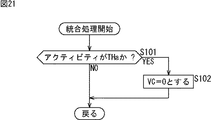
ステップS96において、統合処理部126は、統合処理を実行する。この統合処理の詳細は、図21のフローチャートに示されている。
In step S96, the
ステップS101において、統合処理部126は、ブロックアクティビティが閾値THa 以下か否かを判定する。この判定は、閾値判定部124より供給されたフラグに基づいて行われる。統合処理部126は、ブロックアクティビティが閾値THa以下であると判定した場合、ステップS102において、正規化処理部125が算出した動きベクトル確度VCの値を0に設定する。ステップS101において、アクティビティの値が閾値THaより大きいと判定された場合には、ステップS102の処理はスキップされ、正規化処理部125で生成された動きベクトル確度VCの値が、そのまま動きベクトルとともに出力される。
In step S101, the
これは、正規化処理部125において演算された動きベクトルの確度VCの値が正であったとしても、ブロックアクティビティの値が閾値THaより小さい場合には、正しい動きベクトルが得られていない可能性があるからである。すなわち、図20に示されるように、原点Oと点Pの間においては、曲線132が、曲線131より図中下側に(直線133より下側に)突出することになる。ブロックアクティビティの値が閾値Thaより小さい区間であって、曲線131と曲線132において囲まれる領域R3においては、評価値をブロックアクティビティで割り算して得られる値は、領域R1とR2の両方に分布し、正しい動きベクトルが得られていない可能性が高い。
This is because there is a possibility that a correct motion vector is not obtained if the block activity value is smaller than the threshold value THa even if the value of the motion vector accuracy VC calculated by the
そこで、このような分布状態である場合には、動きベクトルの確度は低いものとして処理するようにする。このため、ステップS102において、動きベクトル確度VCは、その値が正であったとしても、閾値Thaより小さい場合には、0に設定される。このようにすることで、動きベクトル確度VCの値が正である場合には、正しい動きベクトルが得られている場合であることを確実に表すことが可能となる。しかも、動きベクトル確度VCの値が大きい程、正しい動きベクトルが得られている確率が高くなる(分布が領域R1に含まれる確率が高くなる)。 Therefore, in such a distribution state, processing is performed assuming that the accuracy of the motion vector is low. For this reason, in step S102, even if the motion vector accuracy VC is positive, it is set to 0 if it is smaller than the threshold value Tha. In this way, when the value of the motion vector accuracy VC is positive, it is possible to reliably represent that the correct motion vector is obtained. In addition, the larger the value of the motion vector accuracy VC, the higher the probability that a correct motion vector is obtained (the probability that the distribution is included in the region R1 increases).
このことは、一般的に、輝度変化が少ない領域(アクティビティが小さい領域)では信頼性が高い動きベクトルを検出することが困難であるとの経験上の法則とも一致する。 This coincides with an empirical rule that, in general, it is difficult to detect a motion vector with high reliability in a region where the luminance change is small (region where the activity is small).
次に、図22を参照して、図4の背景動き推定部54の構成例について説明する。図22に示されるように、背景動き推定部54は、頻度分布算出部141と背景動き決定部142により構成されている。
Next, a configuration example of the background
頻度分布算出部141は、動きベクトルの頻度分布を算出する。ただし、この頻度には、図4の動き推定部52より供給される動きベクトル確度VC を用いることで、確からしい動きに重みが与えられるように、重み付けが行われる。背景動き決定部142は、頻度分布算出部141により算出された頻度分布に基づいて、頻度が最大となる動きを背景動きとして決定する処理を行い、図4の領域推定関連処理部55へ出力する。
The frequency
図23のフローチャートを参照して、背景動き推定部54が実行する背景動き推定処理について説明する。
The background motion estimation process executed by the background
ステップS111において、頻度分布算出部141は、動き頻度分布を算出する。具体的には、頻度分布算出部141は、背景動きの候補としての動きベクトルのx座標とy座標がそれぞれ基準点から±16画素分の範囲で表されるとすると、1089個(=16×2+1)×(16×2+1))の箱、すなわち動きベクトルがとり得る値に対応する座標分の箱を用意し、動きベクトルが発生した場合、その動きベクトルに対応する座標に1を加算する。このようにすることで、動きベクトルの頻度分布を算出することができる。
In step S111, the frequency
ただし、1個の動きベクトルが発生した場合、1を加算していくと、確度が低い動きベクトルの発生頻度が多い場合、その確実性が低い動きベクトルが背景動きとして決定されてしまう恐れがある。そこで、頻度分布算出部141は、動きベクトルが発生した場合、その動きベクトルに対応する箱(座標)に、値1を加算するのではなく、値1に動きベクトル確度VC を乗算した値(=動きベクトル確度VC の値)を加算する。動きベクトル確度VC の値は、0から1の間の値として正規化されており、その値が1に近いほど確度が高い値である。従って、このようにして得られた頻度分布は、動きベクトルをその確度に基づいて重み付けした頻度分布となる。これにより、確度の低い動きが背景動きとして決定される恐れが少なくなる。
However, when one motion vector is generated, if 1 is added, if the frequency of occurrence of a motion vector with low accuracy is high, a motion vector with low certainty may be determined as the background motion. . Therefore, when a motion vector occurs, the frequency
次に、ステップS112において、頻度分布算出部141は、動き頻度分布を算出する処理を全ブロックについて終了したか否かを判定する。まだ処理していないブロックが存在すると判定された場合、ステップS111に戻り、次のブロックについて動き頻度分布が算出される。
Next, in step S112, the frequency
以上のようにして、全画面に対して動き頻度分布算出処理が行われ、ステップS112において、全ブロックの処理が終了したと判定された場合、ステップS113に進み、背景動き決定部142は、頻度分布の最大値を検索する処理を実行する。すなわち、背景動き決定部142は、頻度分布算出部141により算出された頻度の中から最大の頻度のものを選択し、その頻度に対応する動きベクトルを背景動きの動きベクトルとして決定する。この背景動きの動きベクトルは、図4の領域推定関連処理部55に供給され、全画面動きと背景動きが一致するか否かの判定処理に用いられる。
As described above, the motion frequency distribution calculation processing is performed on the entire screen, and when it is determined in step S112 that the processing of all blocks has been completed, the process proceeds to step S113, where the background motion determination unit 142 A process for searching for the maximum value of the distribution is executed. That is, the background
次に、図24を参照して、図4のシーンチェンジ検出部53の構成例について説明する。図24に示されるように、シーンチェンジ検出部53は、動きベクトル確度平均算出部151と閾値判定部152により構成されている。
Next, a configuration example of the scene
動きベクトル確度平均算出部151は、図4の動き推定部52より供給された動きベクトル確度VC の全画面の平均値を算出し、閾値判定部152に出力する。閾値判定部152は、動きベクトル確度平均算出部151より供給された平均値を、予め定められている閾値と比較し、その比較結果に基づいて、シーンチェンジであるか否かを判定し、判定結果を図4の制御部59に出力する。
The motion vector accuracy
図25のフローチャートを参照して、シーンチェンジ検出部53が実行するシーンチェンジ検出処理について説明する。
The scene change detection process executed by the scene
ステップS121において、動きベクトル確度平均算出部151は、動きベクトル確度の総和を算出する。具体的には、動きベクトル確度平均算出部151は、動き推定部52の統合処理部126より出力された各ブロック毎に算出された動きベクトル確度VCの値を加算する処理を実行する。
In step S121, the motion vector accuracy
ステップS122において、動きベクトル確度平均算出部151は、動きベクトル確度VCの総和を算出する処理が全ブロックについて終了したか否かを判定し、まだ終了していない場合には、ステップS121の処理を繰り返す。この処理を繰り返すことで、1画面分の各ブロックの動きベクトル確度VCの総和が算出される。
In step S122, the motion vector accuracy
ステップS122において、1画面全部についての動きベクトル確度VCの総和の算出処理が終了したと判定された場合、ステップS123に進み、動きベクトル確度平均算出部151は、動きベクトル確度VCの平均値を算出する処理を実行する。具体的には、ステップS121の処理で算出された1画面分の動きベクトル確度VCの総和を、足し込まれたブロック数で除算して得られた値が平均値として算出される。
If it is determined in step S122 that the calculation of the sum of the motion vector accuracy VC for one entire screen has been completed, the process proceeds to step S123, and the motion vector accuracy
ステップS124において、閾値判定部152は、ステップS123の処理で動きベクトル確度平均算出部151により算出された動きベクトル確度VCの平均値を、予め設定されている閾値と比較し、閾値より小さいか否かを判定する。一般的に、動画中の時刻が異なる2フレーム間でシーンチェンジが発生すると、対応する画像が存在しないため、動きベクトルを算出しても、その動きベクトルは確からしくないことになる。そこで、閾値判定部152は、動きベクトル確度VCの平均値が閾値より小さいと判定した場合にはステップS125に進み、シーンチェンジフラグをオンし、閾値以上であると判定した場合にはステップS126に進み、シーンチェンジフラグをオフにする。シーンチェンジフラグのオンは、シーンチェンジがあったことを表し、シーンチェンジフラグのオフは、シーンチェンジが無いことを表す。
In step S124, the
このシーンチェンジフラグは、制御部59へ供給され、図13のステップS61におけるシーンチェンジの有無の判定、並びに図16のステップS72のシーンチェンジの有無の判定に利用される。
This scene change flag is supplied to the
以上のように、図1のオブジェクト追尾部23を構成することにより、追尾すべきオブジェクト41(図3)が回転したり、オクルージョンが発生したり、あるいはシーンチェンジにより、オブジェクト41の追尾点41Aが一時的に表示されなくなるような場合でも、画像の中で移動するオブジェクト41の追尾点41Aを正確に追尾することができる。
As described above, by configuring the
また、このようにして追尾されるオブジェクト41の追尾点41Aの位置情報が、図1のオブジェクト追尾部23による追尾結果として追尾位置補正部24に出力される。すなわち、ユーザは、オブジェクト追尾部23により追尾処理が行われたにもかかわらず所望の追尾結果が得られない場合、指示入力部29を介して追尾位置の補正を指示することにより、その指示を受けた追尾位置補正部24は、オブジェクト追尾部23から供給された追尾結果としての位置情報を補正することができる。
Further, the position information of the
次に、図1の追尾位置補正部24の詳細な構成例と、その動作について説明する。
Next, a detailed configuration example and operation of the tracking
図26は、追尾位置補正部24の機能的構成例を示すブロック図である。図26に示されるように、追尾位置補正部24は、補正値算出部161、補正値反映部162、および微調整部163により構成されている。
FIG. 26 is a block diagram illustrating a functional configuration example of the tracking
補正値算出部161は、指示入力部29を介してユーザより追尾位置の補正が指示された場合、その補正値を算出する。例えば、指示入力部29が上、下、右、左方向を指示することが可能な十字方向ボタンで構成されており、それらのボタンの1回の押下に応じて所定の補正量が予め設定されている場合、ボタンの押下回数に応じてユーザの補正値Δuが算出される。また例えば、指示入力部29が所定方向を指示することが可能なレバーで構成されており、レバーの傾斜角度に応じて所定の補正量が予め設定されている場合、レバーの倒し具合に応じてユーザの補正値Δuが算出される。
When the correction value of the tracking position is instructed by the user via the instruction input unit 29, the correction
補正値反映部162は、オブジェクト追尾部23から供給された追尾結果としての位置情報に、補正値算出部161から供給されたユーザの補正値Δuを反映する。
The correction
ここでは、ブロックマッチング方式などで算出された追尾対象としての追尾点に、ユーザの補正値Δuを反映する例について説明する。 Here, an example in which the correction value Δu of the user is reflected on the tracking point as the tracking target calculated by the block matching method or the like will be described.
図27に示されるように、ブロックマッチング方式によれば、現フレームt=tと次のフレームt=t+1との間の差分ベクトルΔxが算出される。上述したようにしてオブジェクト追尾部23により通常の追尾処理が行われる場合には、次式(6)に基づいて、次のフレームt=t+1の追尾点x(t+1)が算出される。x(t)は現フレームt=tの追尾点である。
As shown in FIG. 27, according to the block matching method, a difference vector Δx between the current frame t = t and the next frame t = t + 1 is calculated. When normal tracking processing is performed by the
![]()
![]()
例えば、算出された差分ベクトルΔxを考慮せず、ユーザの補正値Δuのみを反映させる第1の方法の場合、次式(7)に基づいて、次のフレームt=t+1の追尾点x(t+1)が算出される。 For example, in the case of the first method in which only the user correction value Δu is reflected without considering the calculated difference vector Δx, the tracking point x (t + 1) of the next frame t = t + 1 is based on the following equation (7). ) Is calculated.
![]()
![]()
図28は、第1の方法によりユーザの補正値を反映させる例を示している。図28に示されるように、位置x(t)から位置x(t+2)の間に行われたユーザによる補正が終了した後、補正後の追尾点はx(t+3)の位置とされる。このように、ユーザによる補正値Δuは、画像の座標系に対する相対的な位置として追尾点に反映される。 FIG. 28 shows an example in which the correction value of the user is reflected by the first method. As shown in FIG. 28, after the correction performed by the user between the position x (t) and the position x (t + 2) is completed, the corrected tracking point is set to the position x (t + 3). As described above, the correction value Δu by the user is reflected on the tracking point as a relative position with respect to the coordinate system of the image.
また例えば、算出された差分ベクトルΔxを用いた追尾点と、ユーザの補正値Δuによる追尾点とを別々に保持し、ユーザによる補正が終了した時点でブロックマッチング処理に反映させる第2の方法の場合、次式(8)に基づいて、補正開始時の追尾点u(t)が算出される。 In addition, for example, the tracking point using the calculated difference vector Δx and the tracking point based on the user correction value Δu are separately held and reflected in the block matching process when the correction by the user is completed. In this case, the tracking point u (t) at the start of correction is calculated based on the following equation (8).
![]()
![]()
また次式(9)に基づいて、補正中の追尾点が算出される。 Further, the tracking point being corrected is calculated based on the following equation (9).
さらに次式(10)に基づいて、補正終了時の追尾点x(t+1)が算出される。 Further, a tracking point x (t + 1) at the end of correction is calculated based on the following equation (10).
![]()
![]()
この場合、補正中に出力される追尾点はx'とされるが、オブジェクト追尾部23の内部におけるブロックマッチング処理ではxを用いることがポイントである。
In this case, the tracking point output during correction is x ′, but the point is to use x in the block matching process inside the
図29は、第2の方法によりユーザの補正値を反映させる例を示している。図29に示されるように、位置x(t)から位置x(t+2)の間に行われたユーザによる補正が終了した後、補正後の追尾点はx(t+3)+u(t+3)の位置とされ、この位置が改めてx(t+3)となる。このように、ユーザによる補正値Δuは、追尾対象に対する相対的な位置として反映される。 FIG. 29 shows an example in which the correction value of the user is reflected by the second method. As shown in FIG. 29, after the correction performed by the user between the position x (t) and the position x (t + 2) is completed, the corrected tracking point is the position of x (t + 3) + u (t + 3). This position is again x (t + 3). Thus, the correction value Δu by the user is reflected as a relative position with respect to the tracking target.
なお、指示入力部29に補正量変更ボタンを設けることにより、例えば、ユーザが、補正量変更ボタンを押下しつつ十字方向ボタンやレバーを操作することで、予め設定された補正量を大きく変更することができる。これにより、まず補正量変更ボタンを押下しつつ十字方向ボタンやレバーを操作して大雑把に追尾位置を補正し、その後、補正量変更ボタンを離して十字方向ボタンやレバーを操作して細部の追尾位置を補正することで、短時間で所望の追尾点に補正することが可能である。これは、画像サイズが大きい場合に特に有効である。 By providing a correction amount change button in the instruction input unit 29, for example, the user greatly changes the preset correction amount by operating a cross direction button or lever while pressing the correction amount change button. be able to. As a result, first press the correction amount change button and operate the cross direction button or lever to roughly adjust the tracking position, then release the correction amount change button and operate the cross direction button or lever to track details. By correcting the position, it is possible to correct the desired tracking point in a short time. This is particularly effective when the image size is large.
図26の説明に戻る。微調整部163は、補正値反映部162で第1の方法または第2の方法によりユーザの補正値Δuが反映された追尾点をさらに微調整する。
Returning to the description of FIG. The
ここでは、追尾対象としてのオブジェクトの重心位置に追尾点を微調整する例について説明する。 Here, an example will be described in which the tracking point is finely adjusted to the position of the center of gravity of the object as the tracking target.
例えば、図30に示されるように、位置x(t)から位置x'(t+1)へ、上述した第1の方法を用いてユーザによる補正がなされた場合、補正後の位置x'(t+1)が属しているオブジェクトの範囲201が算出され、そのオブジェクトの重心x(t+1)へ追尾点が微調整される。以後、微調整された追尾点x(t+1)の位置から追尾処理が継続される。 For example, as shown in FIG. 30, when correction by the user is performed from the position x (t) to the position x ′ (t + 1) using the first method described above, the corrected position x ′ (t + 1) Is calculated, and the tracking point is finely adjusted to the center of gravity x (t + 1) of the object. Thereafter, the tracking process is continued from the position of the fine-tuned tracking point x (t + 1).
ここで、色という画素値(色情報)に基づいて追尾点が属するオブジェクトの範囲を求め、その重心を算出する方法について説明する。 Here, a method for obtaining the range of the object to which the tracking point belongs based on the pixel value (color information) called color and calculating the center of gravity will be described.
(1)まず、位置x'(t+1)のRGB色(r',g',b')を算出する。なお、表色系はRGBでなくてもよい。 (1) First, the RGB color (r ′, g ′, b ′) at the position x ′ (t + 1) is calculated. The color system may not be RGB.
(2)RGB色が算出された位置x'(t+1)の周辺画素について、位置x'(t+1の色に近い色を持つ画素を同じオブジェクトに属していると判断する。例えば、次式(11)で表されるΔcが所定の値より小さい画素が位置x'(t+1)と同じオブジェクトに属していると判断される。r、g、bは各周辺画素の色である。 (2) For the peripheral pixel at the position x ′ (t + 1) where the RGB color is calculated, it is determined that a pixel having a color close to the color at the position x ′ (t + 1) belongs to the same object. ) Is smaller than a predetermined value, it is determined that the pixel belongs to the same object as the position x ′ (t + 1), where r, g, and b are the colors of the surrounding pixels.
![]()
![]()
(3)位置x'(t+1)と同じオブジェクトに属している画素の位置から、次式(12)に基づいて、オブジェクトの重心x(t+1)を算出する。Xiは、同じオブジェクトに属している各画素の位置であり、nは、同じオブジェクトに属している画素の総数である。 (3) The center of gravity x (t + 1) of the object is calculated from the position of the pixel belonging to the same object as the position x ′ (t + 1) based on the following equation (12). Xi is the position of each pixel belonging to the same object, and n is the total number of pixels belonging to the same object.
以上のようにして、色情報を用いる方法で追尾点が属するオブジェクトの範囲を求め、その重心位置を算出することにより、追尾点を、追尾点が属するオブジェクトの重心位置に微調整することが可能である。 As described above, it is possible to fine-tune the tracking point to the center of gravity of the object to which the tracking point belongs by obtaining the range of the object to which the tracking point belongs by the method using the color information and calculating the center of gravity position thereof. It is.
なお、このように色情報を用いる方法に限らず、例えば、動きベクトルや輝度値などをもとにしてオブジェクトの範囲を求め、その重心位置を算出するようにしてもよい。例えば、動きベクトルを用いる場合、位置x'(t+1)の動きベクトルと同じまたは似ているベクトルを持つものを同じオブジェクトに属していると判断し、次のようにしてオブジェクトの範囲を求め、その重心を算出することができる。 Note that the present invention is not limited to the method using color information, and for example, a range of an object may be obtained based on a motion vector, a luminance value, or the like, and the center of gravity position may be calculated. For example, when a motion vector is used, it is determined that a vector having the same or similar vector as the motion vector at the position x ′ (t + 1) belongs to the same object, and the range of the object is obtained as follows. The center of gravity can be calculated.
(1)動きベクトル検出
図31に示されるように、追尾点211を中心とした領域212内で、サンプリング間隔(sx,sy)毎に動きベクトルを検出する。領域212の大きさは、サンプル数m,nとして、sx・m×sy・nとなる。動きベクトルの検出には、例えばブロックマッチング方式や勾配法が用いられる。
(1) Motion Vector Detection As shown in FIG. 31, a motion vector is detected at each sampling interval (sx, sy) within a
(2)動きベクトルの頻度分布算出
例えば、処理範囲内の動きの候補を−16<=vx<=16、−16<=vy<=16の整数値(vxは水平動き、vyは垂直動き)で表すとすると、33(=16×2+1)画素×33画素=1089個の箱、すなわち動きベクトルがとり得る値に対応する座標分の箱を用意し、あるサンプル点で(vx,vy)=(2,2)のとき、(2,2)の箱に1を加算する。この処理を処理範囲内の全サンプル点に対して行うことで、動きベクトルの頻度分布を算出することができる。
(2) Motion vector frequency distribution calculation For example, motion candidates within the processing range are represented by integer values of −16 <= vx <= 16 and −16 <= vy <= 16 (vx is horizontal motion, vy is vertical motion) In this case, 33 (= 16 × 2 + 1) pixels × 33 pixels = 1089 boxes, that is, boxes corresponding to coordinates corresponding to possible values of the motion vector are prepared, and at a certain sample point (vx, vy) = When (2, 2), 1 is added to the box of (2, 2). By performing this processing on all sample points within the processing range, the frequency distribution of the motion vector can be calculated.
(3)追尾対象のサンプル点抽出
図32に示されるように、領域212内で多数を占める動き(図32の例においては、左斜め下方向の動き)と類似する動きを示すサンプル点を追尾対象上の点として抽出する。
(3) Extraction of sample points to be tracked As shown in FIG. 32, sample points showing movement similar to the movement occupying a large number in the area 212 (in the example of FIG. 32, the movement to the left obliquely downward) are tracked. Extract as a point on the object.
(4)サンプル点の重心算出
領域212内において追尾対象上のサンプル点であるか否かを表すフラグをflag(i,j)(1<=i<=m,1<=j <=n)として設定する。(3)で追尾対象上のサンプル点として抽出された場合、1に設定され、(3)で追尾対象上のサンプル点として抽出されていない場合、0に設定される。そして、サンプル点の重心G(x,y)は、次式(13)に基づいて、サンプル点P(x,y)として算出される。
(4) Gravity calculation of sample point Flag (i, j) (1 <= i <= m, 1 <= j <= n) indicating whether or not the sample point is a sample point on the tracking target in the
以上のようにして、動きベクトルを用いる方法で追尾点が属するオブジェクトの範囲を求め、その重心位置を算出することも可能である。ユーザによる補正に加え、微調整された先の追尾点は、外乱に対してロバスト性の高い、つまり追尾処理しやすいことを特徴としている。 As described above, the range of the object to which the tracking point belongs can be obtained by the method using the motion vector, and the center of gravity position can be calculated. In addition to the correction by the user, the finely adjusted previous tracking point is characterized by high robustness against disturbance, that is, easy tracking processing.
上述したような追尾補正処理について、図33のフローチャートを参照して説明する。 The tracking correction process as described above will be described with reference to the flowchart of FIG.
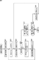
ステップS131において、制御部59は、ユーザにより指示入力部29が用いられ、追尾対象の位置が指定され追尾開始が指示されたか否かを判定し、追尾開始が指示されるまで待機する。そして、ステップS131において、追尾対象の位置が指定され追尾開始が指示されたと判定された場合、処理はステップS132に進む。
In step S131, the
ステップS132において、制御部59は、次のフレームの画像の入力を待機するように各部を制御する。ステップS133において、追尾点決定部57は、次のフレームにおける対象位置を算出する。例えば、図27に示したように、ブロックマッチング方式によれば、現フレームと次のフレームとの間の差分ベクトルΔxが算出され、上記式(6)に基づいて、次のフレームの対象位置である追尾点が算出される。
In step S132, the
ステップS134において、制御部27は、指示入力部29を介してユーザにより位置補正が指示されたか否かを判定し、位置補正が指示されていないと判定した場合、ステップS135に進む。ステップS135において、追尾点決定部57は、ステップS133の処理で算出した対象位置をそのまま次のフレームの対象位置とする。
In step S134, the
一方、ステップS134において、ユーザにより位置補正が指示されたと判定された場合、ステップS136に進み、制御部59は、追尾点決定部57からの追尾結果を追尾位置補正部24に出力する。追尾位置補正部24は、入力された追尾結果にユーザによる補正値を反映したものを次のフレームの対象位置とする。
On the other hand, if it is determined in step S134 that the position correction has been instructed by the user, the process proceeds to step S136, and the
具体的には、補正算出部161により、ユーザからの指示入力部29の操作量(例えば、ボタンの押下回数やレバーの倒し具合)に応じた補正値が算出される。そして、補正値反映部162により、図28を参照して説明した第1の方法、あるいは、図29を参照して説明した第2の方法で、追尾結果にユーザの補正値が反映される。さらに、微調整部163により、追尾対象としてのオブジェクトの重心位置に追尾点が微調整される。
Specifically, the
ステップS137において、制御部27は、ステップS135またはS136の処理による追尾結果に基づいて、画像ディスプレイ25に、撮像部21により撮像された画像に追尾位置を表すマークなどを重畳して表示させる。
In step S137, the
図34の上側図は、撮像部21により撮像された入力画像の例を示し、図34の下側図は、その入力画像の追尾処理が行われた場合の出力画像の例を示している。図34の上側図には、撮像部21により撮像された追尾対象となるオブジェクト221が示されている。図34の下側図には、オブジェクト221の追尾処理が行われ、オブジェクト221の追尾点上にマーク221Aが重畳表示されている。
The upper diagram of FIG. 34 shows an example of an input image captured by the
図33の説明に戻る。ステップS138において、ユーザにより追尾終了が指示されたか否かを判定し、まだ追尾終了が指示されていないと判定した場合、ステップS132に戻り、上述した処理を繰り返す。そして、ステップS138において、追尾終了が指示されたと判定された場合、この追尾位置補正処理は終了される。 Returning to the description of FIG. In step S138, it is determined whether or not the user has instructed the end of tracking. If it is determined that the end of tracking has not been instructed yet, the process returns to step S132 and the above-described processing is repeated. If it is determined in step S138 that the end of tracking has been instructed, the tracking position correction process ends.
このように、追尾処理において、ユーザによる補正に加え、追尾対象の重心位置に微調整されるようにしたので、外乱に対してロバスト性が高くなる。 In this way, in the tracking process, in addition to correction by the user, fine adjustment is made to the position of the center of gravity of the tracking target, so that robustness against disturbance is increased.
ところで、ステップS137の処理の別例として、制御部27は、図35の上側図に示されるように、オブジェクト221の追尾点を中心とした入力画像を切り取り、それを図35の下側図に示されるように拡大したズーム画像として、画像ディスプレイ25に表示させることもできる。即ち、追尾対象の拡大表示も可能である。
By the way, as another example of the process of step S137, the
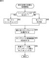
具体的には例えば、制御部27等は、追尾対象の拡大表示を行う場合には、図36の追尾補正処理を実行すればよい。即ち、図36は、追尾補正処理の一例であって、図33とは別の例について説明するフローチャートである。
Specifically, for example, when the enlarged display of the tracking target is performed, the
なお、図36のステップS151乃至S156までの処理は、図33のステップS131乃至S136までの処理と基本的に同様の処理である。よって、ここではその説明を省略する。そこで、以下、ステップS157以降の処理の例を説明する。 Note that the processing from steps S151 to S156 in FIG. 36 is basically the same as the processing from steps S131 to S136 in FIG. Therefore, the description is omitted here. Therefore, an example of processing after step S157 will be described below.
ステップS157において、制御部27は、補正の状況に応じて拡大率を算出する。なお、拡大率の算出手法の詳細については後述する。
In step S157, the
ステップS158において、制御部27は、対象位置を拡大表示して出力する。即ち、制御部27は、ステップS155またはS156の処理(図33のステップS135またはS136と同様の処理)による追尾結果に基づいて、撮像部21により撮像された画像から、対象位置を含むように切り取った画像(図35の例では、上側図の点線枠内の画像)を、ステップS157の処理で算出された拡大率で拡大して、画像ディスプレイ25に表示させる。
In step S158, the
これにより、ステップS158の処理が終了し、処理はステップS159に進む。なお、ステップS159以降の処理は、図33のステップS138以降の処理と基本的に同様の処理である。よって、ここではその説明を省略する。 Thereby, the process of step S158 is complete | finished and a process progresses to step S159. The processing after step S159 is basically the same processing as the processing after step S138 of FIG. Therefore, the description is omitted here.
さらに以下、図36のステップS157とS158の処理(以下、拡大表示処理と称する)の詳細について説明していく。 Further, details of the processing in steps S157 and S158 (hereinafter referred to as enlarged display processing) in FIG. 36 will be described.
先ず、拡大表示における対象位置の表示手法の例について説明する。 First, an example of a method for displaying a target position in enlarged display will be described.
例えば上述した図35の下側図のように、オブジェクト221の対象位置である追尾点上にマーク221Aを重畳表示させる手法を採用することができる。
For example, as shown in the lower view of FIG. 35 described above, a method of superimposing and displaying the
また例えば、図37に示されるように、オブジェクト221の対象位置である追尾点を示すべく、4つのマーク221L,221R,221U,221Dを画像の四隅に表示させる手法を採用できる。即ち、水平の2つのマーク221L,221Rを結ぶ線分と、垂直の2つのマーク221U,221Dを結ぶ線分との交点が、オブジェクト221の対象位置である追尾点を示す。
Also, for example, as shown in FIG. 37, a method of displaying four
なお、拡大表示における対象位置の表示手法は、上述した例に特に限定されないことはいうまでも無い。もっとも、上述した例の様に、画像中の対象位置をユーザが容易に視認できる手法であると好適である。 Needless to say, the display method of the target position in the enlarged display is not particularly limited to the above-described example. However, it is preferable that the method allows the user to easily visually recognize the target position in the image as in the example described above.
次に、拡大率について説明する。 Next, the enlargement ratio will be described.
拡大率は、例えば次式(14)のように定義される。かかる定義によれば、拡大率の最小値は1になる。 The enlargement ratio is defined as, for example, the following formula (14). According to this definition, the minimum value of the enlargement ratio is 1.
拡大率 = 出力画像の大きさ/切り取った画像の大きさ ・・・(14) Magnification factor = size of output image / size of cropped image (14)
例えば、図36のステップS157の処理で拡大率として4が算出された場合、次のステップS158の処理で、切り取った画像の大きさの4倍のズーム画像が生成されて、画像ディスプレイ25に表示されることになる。
For example, when 4 is calculated as the enlargement ratio in the process of step S157 in FIG. 36, a zoom image that is four times the size of the clipped image is generated and displayed on the
この拡大率は、補正の指示をしていない時等に、ユーザが任意の値に設定できるようにしておこくこともできる。 This enlargement ratio can be set so that the user can set an arbitrary value when no correction instruction is given.
また、当然ながら、拡大率を固定しておくこともできる。しかしながら、ユーザが補正する際にも常に拡大率が一定であるとすると、オブジェクト221の周囲の状況が見えづらくなるときもある。その結果、ユーザにとっては、補正操作がしにくくなってしまうこともある。
Of course, the enlargement ratio can be fixed. However, if the enlargement ratio is always constant when the user corrects, the situation around the
例えば上述した図35の上側図において、追尾対象であるオブジェクト221と、別オブジェクト222との相対位置に基づいて、追尾対象であるオブジェクト221の位置の補正を行いたいとユーザが所望する場合がある。かかる場合に、図35の下側図に示されるような拡大表示がなされた場合、別オブジェクト222は全く見えなくなる。その結果、ユーザは、別オブジェクト222との相対位置を把握できず、補正操作がしにくくなってしまう。
For example, in the upper side view of FIG. 35 described above, the user may desire to correct the position of the
そこで、制御部27は、周囲の状況を見やすくしてユーザの補正操作の容易化を支援すべく、補正時に拡大率を自動的に調整することができる。
Therefore, the
ここで、拡大率の自動的な調整とは、ユーザの指示操作を介在せずに、制御部27が自律的な判断で拡大率を算出し、その拡大率で画像を拡大表示させることをいう。
Here, the automatic adjustment of the enlargement ratio means that the
換言すると、ユーザが位置を補正しながら拡大率を手動操作で調整するといった手動調整に対する調整が、拡大率の自動的な調整である。即ち、拡大率の調整として、手動調整を採用することもできる。ただし、この場合、ユーザは、拡大率の手動調整を行うのと同時に、複数の別の操作をしなければならない。即ち、ユーザは非常に困難で煩雑な操作をしなければならない。よって、手動調整を採用した場合には、ユーザの補正操作の容易化という目的に反することになる。そこで、本実施の形態では、拡大率の調整として、自動調整を採用して、ユーザの複雑な操作を省力化するようにしているのである。 In other words, the adjustment for the manual adjustment in which the user manually adjusts the enlargement ratio while correcting the position is an automatic adjustment of the enlargement ratio. That is, manual adjustment can be adopted as the adjustment of the enlargement ratio. However, in this case, the user must perform a plurality of other operations simultaneously with the manual adjustment of the enlargement ratio. That is, the user must perform a very difficult and complicated operation. Therefore, when manual adjustment is adopted, it goes against the purpose of facilitating the user's correction operation. Therefore, in the present embodiment, automatic adjustment is adopted as adjustment of the enlargement ratio so as to save labor for complicated user operations.
以下、自動調整についてさらに詳しく説明していく。 Hereinafter, the automatic adjustment will be described in more detail.
図38は、自動調整の基本的な概念を説明する図である。図38の上側の画像、即ち、時刻taにおいて表示されている画像は、補正がなされていない時の画像を示している。 FIG. 38 is a diagram for explaining the basic concept of automatic adjustment. The upper image in FIG. 38, that is, the image displayed at time ta shows an image when correction is not performed.
その時刻taの後、補正が開始されたとする。即ち、各フレームについて図36のステップS154の処理でYESであると判定されたとする。この場合、制御部27は、各フレームについてのステップS157とS158の拡大表示処理で、拡大率を自動的に小さくしていく。即ち、一連の各画像(各フレームの画像)が拡大率が小さくなりつつ出力されていくことになる。従って、ユーザにとっては、オブジェクト221はだんだんと縮小されていく代わりに、周囲の状況がだんだんと見えるようになってくる。例えば、図38の中央の画像、即ち、時刻tbにおいて表示されている画像が、拡大率が自動的に小さくされ、別オブジェクト222等の周囲の状況が見えるようになった画像(所定フレームの画像)の一例を示している。
It is assumed that correction is started after the time ta. In other words, it is assumed that YES is determined in step S154 of FIG. 36 for each frame. In this case, the
その時刻tbの後、補正が終了されたとする。即ち、図36のステップS154の処理でNOであると判定されるようになったとする。この場合、制御部27は、それ以降の各フレームについてのステップS157とS158の拡大表示処理で、拡大率を自動的に大きくしていき、最終的に元の拡大率まで戻す。即ち、一連の各画像(各フレームの画像)が拡大率が大きくなりつつ出力されていくことになる。従って、ユーザにとっては、今度は、オブジェクト221はだんだんと拡大されていき、元の大きさに戻るように見えることになる。例えば、図38の下側の画像、即ち、時刻tcにおいて表示されている画像が、オブジェクト221の大きさが元に戻った画像(拡大率が元に戻った段階の所定フレームの画像)の一例を示している。
It is assumed that the correction is finished after the time tb. In other words, it is assumed that NO is determined in the process of step S154 of FIG. In this case, the
具体的には例えば、拡大率は、図39に示されるように変化していく。即ち、図39は、自動調整時の拡大率の時間変化の一例を示している。 Specifically, for example, the enlargement ratio changes as shown in FIG. That is, FIG. 39 shows an example of the change over time of the enlargement ratio during automatic adjustment.
図39において、横軸は時間軸を示しており、縦軸は拡大率を示している。 In FIG. 39, the horizontal axis represents the time axis, and the vertical axis represents the enlargement ratio.
また、拡大率に関して、Zaは、通常時の拡大率、即ち補正なし時の拡大率を示している。Zbは、自動調整時における拡大率の規定値を示している。即ち、拡大率Zbとは、自動的に拡大率を変化させる時の下限値を示している。拡大率Zbは、後述するように可変することも可能であるが、ここでは説明の簡略上、あらかじめ定義された固定値が採用されているとする。 As for the enlargement ratio, Za represents the enlargement ratio at the normal time, that is, the enlargement ratio without correction. Zb represents a specified value of the enlargement ratio at the time of automatic adjustment. That is, the enlargement ratio Zb indicates a lower limit value when the enlargement ratio is automatically changed. The enlargement factor Zb can be varied as will be described later, but here, a fixed value defined in advance is adopted for simplicity of explanation.
また、時間に関しては、t0は、ユーザが補正を始めた時刻を示している。t1は、拡大率が規定値に到達する時刻を示している。t2は、ユーザが補正を終えた時刻を示している。t3は、元の拡大率に戻る時刻を示している。 Regarding time, t0 indicates the time when the user started correction. t1 indicates the time at which the enlargement rate reaches the specified value. t2 indicates the time when the user finished the correction. t3 indicates the time to return to the original enlargement ratio.
この場合、制御部27は、時刻t0乃至t1間の各フレームおよび時刻t2乃至t3間の各フレームについての各ステップS157の処理として、制御部27は、例えば次のようにして、各フレームの拡大率をそれぞれ算出することができる。
In this case, as a process of each step S157 for each frame between times t0 and t1 and each frame between times t2 and t3, the
例えば、制御部27は、自動調整の所要時間を定義することで、各フレームの拡大率をそれぞれ算出することができる。
For example, the
具体的には例えば、次式(15)に示される時刻t0乃至t1間の所要時間△T01と、次式(16)に示される時刻t1乃至t2間の所要時間△T23について、あらかじめ定義した時間を設定しておく。 Specifically, for example, a predetermined time for a required time ΔT01 between times t0 and t1 shown in the following equation (15) and a required time ΔT23 between times t1 and t2 shown in the following equation (16): Is set in advance.
△T01 =t1−t0 ・・・(15)
△T23 =t3−t2 ・・・(16)
△ T01 = t1−t0 (15)
△ T23 = t3−t2 (16)
そして、制御部27は、次の式(17)と式(18)とを用いて、拡大率の変化速度(単位時間あたりの拡大率の変化量)△V01および△V23 を算出する。
Then, the
△V01 = (Zb − Za)/△T01 ・・・(17)
△V23 = (Za − Zb)/△T23 ・・・(18)
ΔV01 = (Zb − Za) / ΔT01 (17)
△ V23 = (Za-Zb) / △ T23 (18)
最終的に、制御部27は、この算出された変化速度△V01および△V23 に従って拡大率を決定する。これにより、定義されている所要時間△T01または△T23で、拡大率の変化を完了させることができるようになる。ただし、拡大率の変化速度は補正前の拡大率Zaによって左右される点に留意する。
Finally, the
なお、時刻t0乃至t1間の各フレームおよび時刻t2乃至t3間の各フレームの拡大率の算出手法は、上述した式(15)乃至式(18)を用いる手法に特に限定されない。その他例えば、拡大率の変化速度(単位時間あたりの拡大率の変化量)を定義しておき、この定義された変化速度に基づいて拡大率を決定する、という手法を採用することができる。かかる手法を採用した場合には、定義された変化速度で拡大率を変化させることができるようになる。ただし、所要時間△T01,△T23は補正前の拡大率Zaによって左右される点に留意する。 Note that the method for calculating the enlargement ratio of each frame between times t0 and t1 and each frame between times t2 and t3 is not particularly limited to the method using Equations (15) to (18) described above. In addition, for example, it is possible to adopt a method in which a change rate of the enlargement rate (a change amount of the enlargement rate per unit time) is defined and the enlargement rate is determined based on the defined change rate. When such a method is employed, the enlargement ratio can be changed at a defined change rate. However, it should be noted that the required times ΔT01 and ΔT23 depend on the enlargement ratio Za before correction.
また、時刻t0乃至t1間および時刻t2乃至t3間の拡大率の変化のパターンは、図39の例に特に限定されない。即ち、拡大率を直線的に変化させるパターンに特に限定されない。その他例えば、曲線的に変化させるパターンを採用することもできる。 Also, the change pattern of the enlargement ratio between the times t0 to t1 and between the times t2 to t3 is not particularly limited to the example of FIG. That is, the pattern is not particularly limited to a pattern in which the enlargement ratio is linearly changed. In addition, for example, it is possible to adopt a pattern that changes in a curved manner.
また、拡大率Zbは、上述した例では固定されていたが、次に示す各種手法を採用することで可変することもできる。なお、次に示す各種手法は、組み合わせることもできる。 Moreover, although the enlargement ratio Zb is fixed in the above-described example, it can be changed by employing the following various methods. The following various methods can be combined.
拡大率Zbの可変手法の例としては、例えば、ユーザによる指定手法、オブジェクトに応じた自動調整手法、および、補正量に応じた拡大率手法といった手法が考えられる。以下、これらの手法について個別に説明していく。 As an example of a variable method of the enlargement factor Zb, for example, a method designated by the user, an automatic adjustment method according to an object, and a method such as an enlargement factor method according to a correction amount can be considered. Hereinafter, these methods will be described individually.
はじめに、ユーザによる指定手法について説明する。 First, the designation method by the user will be described.
ユーザによる指定手法とは、拡大率Zbをユーザが直接指定できる手法をいう。ユーザによる指定手法の具体例としては、例えば、絶対値による指定手法や、相対値による指定手法を採用することができる。 The designation method by the user means a method by which the user can directly specify the enlargement ratio Zb. As a specific example of the designation method by the user, for example, a designation method based on an absolute value or a designation method based on a relative value can be adopted.
絶対値による指定方法とは、ユーザが、所望する拡大率Zbを、例えば「1.0」というように数値そのもの(絶対値)によって直接指定したり、入力画像の座標系における画素数を示す数値(絶対値)によって指定する手法をいう。 The designation method using the absolute value is a method in which the user directly designates a desired enlargement ratio Zb by a numerical value itself (absolute value) such as “1.0”, or a numerical value (absolute value) indicating the number of pixels in the coordinate system of the input image. A method specified by (value).
相対値による指定方法とは、ユーザが、所望する拡大率Zbを、例えば「元の拡大率Zaの1/2倍」というように元の拡大率Zaに対する相対値によって指定したり、入力画像の座標系における画素数に対する割合といった相対値によって指定する手法をいう。 The designation method based on the relative value is that the user designates the desired enlargement factor Zb by a relative value with respect to the original enlargement factor Za, for example, “1/2 times the original enlargement factor Za”, A method of designating by a relative value such as a ratio to the number of pixels in the coordinate system.
なお、拡大率Zbの数値として、絶対値換算して1未満となる数値を指定することもできる。ただし、その場合の画像表示には、操作のし易さの観点からはあまり意味はないと思われる。即ち、操作のし易さとは別の目的がある場合に、拡大率Zbの数値として、絶対値換算して1未満となる数値を指定できるようにするとよい。 Note that a numerical value that is less than 1 in terms of absolute value can be designated as the numerical value of the enlargement ratio Zb. However, the image display in that case does not seem to make much sense from the viewpoint of ease of operation. That is, when there is a purpose other than the ease of operation, it is preferable that a numerical value that is less than 1 in terms of absolute value can be designated as the numerical value of the enlargement ratio Zb.
また、上述した例では、Zb≦Zaであることが前提とされていた。従って、この前提が成り立たない場合には、例外的な措置、例えば強制的に拡大率Zb=Zaと変更する等の措置が必要である点留意する。 In the above-described example, it was assumed that Zb ≦ Za. Therefore, if this premise is not satisfied, it should be noted that exceptional measures such as forcibly changing the enlargement ratio Zb = Za are necessary.
次に、オブジェクトに応じた自動調整手法について説明する。 Next, an automatic adjustment method according to the object will be described.
オブジェクトに応じた自動調整手法とは、拡大率Zbを、現在追尾しているオブジェクトの大きさに応じて自動的に調整する手法をいう。 The automatic adjustment method according to the object refers to a method of automatically adjusting the enlargement ratio Zb according to the size of the object currently being tracked.
例えば図40は、オブジェクトに応じた自動調整手法の一例を説明する図である。図40の上側の画像、即ち、時刻tαにおいて表示されている画像は、補正がなされていない時の画像を示している。即ち、補正がなされていないときの元の拡大率Zaの状態では、オブジェクト221が出力画像からはみ出していることが前提となっている。
For example, FIG. 40 is a diagram illustrating an example of an automatic adjustment method according to an object. The upper image in FIG. 40, that is, the image displayed at time tα shows an image when no correction is made. That is, it is assumed that the
その時刻tαの後、補正が開始されたとする。即ち、各フレームについて図36のステップS154の処理でYESであると判定されるようになったとする。この場合、制御部27は、各フレームについてのステップS157とS158の拡大表示処理で、拡大率を自動的に小さくしていく。その際、制御部27は、補正時である図40の時刻tβには、図40の中央の画像が表示されるように、即ち、補正時にはオブジェクト221がちょうど出力画像いっぱいに表示されるように、拡大率Zbを自動調整する。
It is assumed that correction is started after the time tα. That is, assume that YES is determined in step S154 of FIG. 36 for each frame. In this case, the
なお、その時刻tβの後、補正が終了されたとする。即ち、図36のステップS154の処理でNOであると判定されるようになったとする。この場合、制御部27は、それ以降の各フレームについてのステップS157とS158の拡大表示処理で、拡大率を自動的に大きくしていき、最終的に元の拡大率Zaまで戻す。即ち、一連の各画像(各フレームの画像)が拡大率が大きくなりつつ出力されていくことになる。従って、ユーザにとっては、オブジェクト221はだんだんと拡大されていき、元の大きさに戻るように見えることになる。例えば、図40の下側の画像、即ち、時刻tγにおいて表示されている画像が、オブジェクト221の大きさが元に戻った画像(元の拡大率Zaに戻った段階の所定フレームの画像)の一例を示している。
It is assumed that the correction is finished after the time tβ. In other words, it is assumed that NO is determined in the process of step S154 of FIG. In this case, the
この場合、ユーザによる指定手法と組み合わせて、例えばオブジェクト221の大きさの1/2というように、オブジェクト221の大きさに対する相対値で拡大率Zbを指定できるようにしてもよい。
In this case, in combination with the designation method by the user, the enlargement ratio Zb may be designated by a relative value with respect to the size of the
その他、オブジェクトに応じた自動調整手法としては、例えば、追尾点(図40の例等ではオブジェクト221)の動き量△xに応じて拡大率Zbを自動調整するという手法も採用できる。具体的には例えば、動き量△xが大きいときは拡大率Zbを小さくし、動き量が小さいときは拡大率Zbを大きくするという手法を採用できる。この手法は、動きが大きい(速い)場合はより広範囲な画像を表示した方が操作しやすいだろうし、逆に遅い場合はあまり拡大率を変える必要もないだろうという理由に基づく手法である。
In addition, as an automatic adjustment method according to the object, for example, a method of automatically adjusting the enlargement ratio Zb according to the movement amount Δx of the tracking point (the
次に、補正量に応じた拡大率手法について説明する。 Next, an enlargement ratio method according to the correction amount will be described.
補正量に応じた拡大率手法とは、ユーザは追尾点たる対象位置の補正を行う場合、この補正量△uに応じて拡大率Zbを自動的に調整する手法をいう。例えば、補正量△uが大きいときは拡大率Zbを小さくし、補正量△uが小さいときは拡大率Zbを大きくするという手法が、補正量に応じた拡大率手法の一例である。この例の手法は、大きな補正を行う場合は、より広範囲な画像を表示した方が操作しやすいだろうし、逆に小さな補正を行う場合はあまり拡大率を変えない方がいいだろうという理由に基づく手法である。 The enlargement factor method according to the correction amount is a method in which the user automatically adjusts the enlargement factor Zb according to the correction amount Δu when the target position as the tracking point is corrected. For example, the method of reducing the enlargement factor Zb when the correction amount Δu is large and increasing the enlargement factor Zb when the correction amount Δu is small is an example of the enlargement factor method according to the correction amount. The method of this example is because it is easier to operate when displaying a wider range of images when performing large corrections, and it is better not to change the enlargement ratio too much when performing small corrections. It is a method based on this.
以上、拡大率Zbの可変手法について説明した。 The method for changing the enlargement ratio Zb has been described above.
以上説明した拡大率Zbの可変と同様に、拡大率の変化量を可変することもできる。即ち、拡大率の変化量は、上述した例では固定されていたが、次に示す各種手法を採用することで可変することもできる。なお、次に示す各種手法は、組み合わせることもできる。 Similar to the change of the enlargement factor Zb described above, the change amount of the enlargement factor can be changed. That is, the change amount of the enlargement ratio is fixed in the above-described example, but can be changed by employing the following various methods. The following various methods can be combined.
拡大率の変化量の可変手法の例としても、拡大率Zbの可変手法と同様に、ユーザによる指定手法、オブジェクトに応じた自動調整手法、および、補正量に応じた拡大率手法といった手法が考えられる。 As an example of the variable method of the change rate of the enlargement ratio, similar to the variable method of the enlargement ratio Zb, there are methods such as a user designation method, an automatic adjustment method according to the object, and an enlargement rate method according to the correction amount. It is done.
例えば、ユーザによる指定手法としては、直線的に変化する方法、滑らかに変化する(例えばスプライン曲線など)方法、といった複数の選択肢からユーザが選べるようにしておく手法を採用できる。 For example, as the designation method by the user, a method in which the user can select from a plurality of options such as a method of changing linearly and a method of changing smoothly (for example, a spline curve) can be adopted.
例えば、オブジェクトに応じた自動調整手法としては、拡大率Zbの可変手法によってオブジェクトの大きさに応じた拡大率Zbが算出された場合、この拡大率Zbと拡大率Zaとの差に応じて拡大率の変化量を調整する、という手法を採用できる。具体的には例えば、その差(Za−Zb)が大きい場合は拡大率の変化量を大きくし、その差が小さい場合には拡大率の変化量を小さくするという手法を採用できる。この手法は、オブジェクトの全体像が見えにくくなっている(差が大きい)場合には速く見えるようにしてやった方が操作しやすいだろうし、逆の場合も同様であるという理由に基づく手法である。 For example, as an automatic adjustment method according to the object, when the enlargement factor Zb corresponding to the size of the object is calculated by the variable method of the enlargement factor Zb, enlargement is performed according to the difference between the enlargement factor Zb and the enlargement factor Za. A technique of adjusting the rate change rate can be adopted. Specifically, for example, when the difference (Za−Zb) is large, a method of increasing the change amount of the enlargement ratio, and when the difference is small, a method of reducing the change amount of the enlargement ratio can be employed. This method is based on the reason that if it is difficult to see the whole image of the object (the difference is large), it will be easier to operate by making it look faster, and vice versa. .
また例えば、オブジェクトに応じた自動調整手法としては、追尾点(オブジェクト)の動き量△xに応じて拡大率の変化量を自動調整する手法を採用できる。具体的には例えば、動き量△xが大きいときは拡大率の変化量を大きくし、動き量△xが小さいときは拡大率の変化量を小さくするという手法を採用できる。この手法は、動きが大きい(速い)場合はより広範囲な画像を速く表示した方が操作しやすいだろうし、逆の場合も同様であるという理由に基づく手法である。 For example, as an automatic adjustment method according to the object, a method of automatically adjusting the change amount of the enlargement ratio according to the movement amount Δx of the tracking point (object) can be adopted. Specifically, for example, a method of increasing the amount of change in the enlargement ratio when the amount of movement Δx is large and reducing the amount of change in the enlargement ratio when the amount of movement Δx is small can be employed. This method is based on the reason that if the movement is large (fast), it would be easier to operate if a wider range of images were displayed faster, and vice versa.
例えば、補正量に応じた拡大率手法としては、ユーザの追尾位置の補正におけるその補正量△uが大きいときは拡大率の変化量を大きくし、補正量△uが小さいときは拡大率の変化量を小さくするという手法を採用できる。この手法は、大きな補正を行う場合は、より広範囲な画像を速く表示した方が操作しやすいだろうし、逆の場合も同様であるという理由に基づく手法である 。 For example, as an enlargement ratio method according to the correction amount, when the correction amount Δu in the correction of the tracking position of the user is large, the change amount of the enlargement factor is increased, and when the correction amount Δu is small, the change of the enlargement factor is A method of reducing the amount can be adopted. This method is based on the reason that when a large correction is performed, it is easier to operate if a wider range of images is displayed faster, and vice versa.
次に、図41のフローチャートを参照して、図5のステップS11の通常処理に続いて行われる、ステップS12の例外処理の他の例について説明する。この処理は、基本的に、図12の処理と同様の処理であり、図9のステップS24において追尾点の動きを推定することが不可能と判定され、さらにステップS28において追尾点を乗り換える乗り換え候補が選択できなかったと判定された場合に実行される。 Next, another example of the exception process at step S12 performed following the normal process at step S11 in FIG. 5 will be described with reference to the flowchart in FIG. This process is basically the same as the process of FIG. 12, and it is determined in step S24 of FIG. 9 that it is impossible to estimate the movement of the tracking point, and further, the transfer candidate for changing the tracking point in step S28. This is executed when it is determined that cannot be selected.
ステップS171乃至S175の処理は、上述した図12のステップS51乃至S55の処理と同様であるため、その説明は簡略する。すなわち、ステップS171において、例外処理の初期化処理が実行され、ステップS172において、次のフレームの画像の入力が待機され、ステップS173において、テンプレート探索範囲内においてテンプレートマッチング処理が行われ、ステップS174において、通常処理への復帰が可能であるか否かが判定され、通常処理への復帰が可能であると判定された場合、図5のステップS11の通常処理に戻され、通常処理への復帰が可能ではないと判定された場合、ステップS175において、継続判定処理が実行される。 Since the processing of steps S171 to S175 is the same as the processing of steps S51 to S55 of FIG. 12 described above, the description thereof will be simplified. That is, in step S171, exception process initialization processing is executed. In step S172, an input of an image of the next frame is awaited. In step S173, template matching processing is performed within the template search range. In step S174. When it is determined whether or not it is possible to return to the normal process, and when it is determined that the return to the normal process is possible, the process returns to the normal process of step S11 in FIG. If it is determined that it is not possible, a continuation determination process is executed in step S175.
そして、ステップS176において、制御部59は、ステップS175の継続判定処理による例外処理での追尾点の追尾が継続可能であるか否かの継続判定結果に基づいて(図16のステップS76,78で設定されたフラグに基づいて)判定する。追尾点の追尾処理が継続可能であると判定された場合、処理はステップS172に戻り、それ以降の処理が繰り返し実行される。すなわち、追尾点が再び出現するまで待機する処理が繰り返し実行される。
In step S176, the
これに対して、ステップS176において、例外処理での追尾点の追尾処理が継続可能ではないと判定された場合(図16のステップS75の処理で追尾点が消失した後の経過フレーム数が閾値THfr以上と判定されるか、または、ステップS77の処理でシーンチェンジ数が閾値THsc以上と判定された場合)、ステップS177に進み、制御部59は、追尾点決定部57を制御し、保持しておいた追尾点を設定させる。その後、処理は図5のステップS11の通常処理に戻る。
On the other hand, when it is determined in step S176 that the tracking process of the tracking point in the exception process cannot be continued (the number of elapsed frames after the tracking point disappeared in the process of step S75 in FIG. 16 is the threshold THfr). If it is determined as above, or if the number of scene changes is determined to be greater than or equal to the threshold THsc in the process of step S77), the process proceeds to step S177, and the
このように、例外処理での追尾点の追尾が不可能になった場合には、保持しておいた追尾点を用いて再度通常処理に戻ることができるようにしたので、追尾処理を継続的に行うことが可能となる。 In this way, when tracking of the tracking point in exception processing becomes impossible, it is possible to return to normal processing again using the tracking point that has been held, so the tracking processing is continued. Can be performed.
以上においては、追尾処理によって所望の結果が得られていないと判断された場合、ユーザによる補正指示に基づいて、リアルタイムにユーザ補正が反映されるため、継続的に追尾処理を行うことができる。これにより、追尾点の指定や修正時の負荷が軽減し、より好適な追尾結果を得ることが可能となる。 In the above, when it is determined that the desired result is not obtained by the tracking process, the user correction is reflected in real time based on the correction instruction from the user, and therefore the tracking process can be continuously performed. Thereby, the load at the time of designating and correcting the tracking point is reduced, and a more suitable tracking result can be obtained.
また以上においては、監視カメラシステムに適用した場合の例について説明したが、これに限らず、例えば、テレビジョン受像機など各種の画像処理装置に適応することが可能である。 In the above description, an example in which the present invention is applied to a surveillance camera system has been described. However, the present invention is not limited thereto, and can be applied to various image processing apparatuses such as a television receiver.
さらに以上においては、画像の処理単位をフレームとしたが、フィールドを処理単位とすることももちろん可能である。 Further, in the above, the image processing unit is a frame, but it is of course possible to use a field as a processing unit.
上述した一連の処理は、ハードウエアにより実行させることもできるし、ソフトウエアにより実行させることもできる。一連の処理をソフトウエアにより実行させる場合には、そのソフトウエアを構成するプログラムが、専用のハードウエアに組み込まれているコンピュータ、または、各種のプログラムをインストールすることで、各種の機能を実行することが可能な、例えば汎用のパーソナルコンピュータなどに、プログラム記録媒体からインストールされる。 The series of processes described above can be executed by hardware or can be executed by software. When a series of processing is executed by software, a program constituting the software executes various functions by installing a computer incorporated in dedicated hardware or various programs. For example, it is installed from a program recording medium in a general-purpose personal computer or the like.
図42は、上述した一連の処理をプログラムにより実行するパーソナルコンピュータの構成の例を示すブロック図である。 FIG. 42 is a block diagram showing an example of the configuration of a personal computer that executes the above-described series of processing by a program.
図42において、CPU(Central Processing Unit)301は、ROM(Read Only Memory)302、または記憶部308に記憶されているプログラムに従って各種の処理を実行する。RAM(Random Access Memory)303には、CPU301が実行するプログラムやデータなどが適宜記憶される。これらのCPU301、ROM302、およびRAM303は、バス304により相互に接続されている。
42, a CPU (Central Processing Unit) 301 executes various processes according to a program stored in a ROM (Read Only Memory) 302 or a
CPU301にはまた、バス304を介して入出力インタフェース305が接続されている。入出力インタフェース305には、キーボード、マウス、マイクロホンなどよりなる入力取得部306、ディスプレイ、スピーカなどよりなる出力部307が接続されている。CPU301は、入力取得部306から入力される指令に対応して各種の処理を実行する。そして、CPU301は、処理の結果を出力部207に出力する。
An input /
入出力インタフェース305に接続されている記憶部308は、例えばハードディスクからなり、CPU301が実行するプログラムや各種のデータを記憶する。通信部309は、インターネットやローカルエリアネットワークなどのネットワークを介して外部の装置と通信する。
The
また、通信部309を介してプログラムを取得し、記憶部308に記憶してもよい。
A program may be acquired via the
入出力インタフェース305に接続されているドライブ310は、磁気ディスク、光ディスク、光磁気ディスク、或いは半導体メモリなどのリムーバブルメディア311が装着されたとき、それらを駆動し、そこに記録されているプログラムやデータなどを取得する。取得されたプログラムやデータは、必要に応じて記憶部308に転送され、記憶される。
A drive 310 connected to the input /
コンピュータにインストールされ、コンピュータによって実行可能な状態とされるプログラムを格納するプログラム記録媒体は、図42に示されるように、磁気ディスク(フレキシブルディスクを含む)、光ディスク(CD-ROM(Compact Disc-Read Only Memory),DVD(Digital Versatile Disc)を含む)、光磁気ディスク、もしくは半導体メモリなどよりなるパッケージメディアであるリムーバブルメディア311若しくは図1のリムーバブルメディア28、または、プログラムが一時的もしくは永続的に格納されるROM302や、記憶部308を構成するハードディスクなどにより構成される。プログラム記録媒体へのプログラムの格納は、必要に応じてルータ、モデムなどのインタフェースである通信部309を介して、ローカルエリアネットワーク、インターネット、デジタル衛星放送といった、有線または無線の通信媒体を利用して行われる。
As shown in FIG. 42, a program recording medium that stores a program that is installed in a computer and is ready to be executed by the computer includes a magnetic disk (including a flexible disk), an optical disk (CD-ROM (Compact Disc-Read). 1), a
なお、本明細書において、プログラムを記述するステップは、記載された順序に沿って時系列的に行われる処理はもちろん、必ずしも時系列的に処理されなくとも、並列的あるいは個別に実行される処理をも含むものである。 In this specification, the steps for describing a program are not only processes performed in time series in the order described, but also processes that are executed in parallel or individually even if they are not necessarily processed in time series. Is also included.
なお、本発明の実施の形態は、上述した実施の形態に限定されるものではなく、本発明の要旨を逸脱しない範囲において種々の変更が可能である。 The embodiment of the present invention is not limited to the above-described embodiment, and various modifications can be made without departing from the gist of the present invention.
1 監視カメラシステム, 21 撮像部, 22 追尾対象検出部, 23 オブジェクト追尾部, 51 テンプレートマッチング部, 52 動き推定部, 53 シーンチェンジ検出部, 54 背景動き推定部, 55 領域推定関連処理部, 56 乗り換え候補保持部, 57 追尾点決定部, 58 テンプレート保持部, 161 補正値算出部, 162 補正値反映部, 163 微調整部
DESCRIPTION OF
Claims (13)
画像の中の前記オブジェクトの移動を追尾する追尾手段と、
前記追尾手段による前記オブジェクトの追尾中に前記オブジェクト上の追尾点の補正が指示された場合、前記オブジェクトの追尾処理を継続しつつその補正指示を追尾結果に反映する反映手段と、
前記補正が指示された場合、前記画像の表示の拡大率を自律的な判断で調整し、調整後の拡大率で前記画像を拡大表示させる表示制御手段と
を備える画像処理装置。 In an image processing apparatus that tracks a moving object,
Tracking means for tracking the movement of the object in the image;
When correction of the tracking point on the object is instructed during tracking of the object by the tracking means, reflecting means for reflecting the correction instruction on the tracking result while continuing the tracking processing of the object;
An image processing apparatus comprising: a display control unit that adjusts an enlargement ratio of the display of the image by autonomous determination when the correction is instructed, and displays the image in an enlarged manner with the adjusted enlargement ratio.
請求項1に記載の画像処理装置。 When the correction is started as the adjustment of the enlargement ratio, the display control means decreases the enlargement ratio from the first enlargement ratio to the second enlargement ratio, and sets the enlargement ratio to the second enlargement ratio. The image processing apparatus according to claim 1, wherein the image processing apparatus maintains the enlargement ratio and increases the enlargement ratio from the second enlargement ratio to the first enlargement ratio when the correction is completed.
前記第1の拡大率から前記第2の拡大率までの第1の期間における前記拡大率の調整については、前記第1の期間中の拡大率の変化速度に基づいて前記拡大率を算出し、
前記第2の拡大率から前記第1の拡大率までの第2の期間における前記拡大率の調整については、前記第2の期間中の拡大率の変化速度に基づいて前記拡大率を算出する
請求項2に記載の画像処理装置。 The display control means includes
For the adjustment of the enlargement ratio in the first period from the first enlargement ratio to the second enlargement ratio, the enlargement ratio is calculated based on the change rate of the enlargement ratio during the first period,
Regarding the adjustment of the enlargement factor in the second period from the second enlargement factor to the first enlargement factor, the enlargement factor is calculated based on the change rate of the enlargement factor during the second period. Item 3. The image processing apparatus according to Item 2.
前記表示制御手段は、
前記第1の期間における前記拡大率の調整については、前記第1の期間に基づいて前記変化速度を算出し、その変化速度を用いて前記拡大率を算出し、
前記第2の変化の期間における前記拡大率の調整については、前記第2の期間に基づいて前記変化速度を算出し、その変化速度を用いて前記拡大率を算出する
請求項3に記載の画像処理装置。 The first period and the second period are predefined,
The display control means includes
For the adjustment of the enlargement ratio in the first period, calculate the change rate based on the first period, calculate the enlargement ratio using the change rate,
The image according to claim 3, wherein the adjustment of the enlargement ratio in the second change period is calculated based on the second period, and the enlargement ratio is calculated using the change speed. Processing equipment.
請求項3に記載の画像処理装置。 The image processing apparatus according to claim 3, wherein the change rate during the first period and the change rate during the second period are defined in advance.
請求項2に記載の画像処理装置。 The image processing apparatus according to claim 2, wherein the display control unit adjusts the enlargement ratio by changing the second enlargement ratio.
前記第1の拡大率から前記第2の拡大率までの第1の期間中の拡大率の変化速度を可変させて、前記第1の期間中の前記拡大率を調整し、
前記第2の拡大率から前記第1の拡大率までの第2の期間中の拡大率の変化速度を可変させて、前記第2の期間中の前記拡大率を調整する
請求項2に記載の画像処理装置。 The display control means includes
Varying the magnification rate change rate during the first period from the first magnification rate to the second magnification rate, and adjusting the magnification rate during the first period;
The zoom ratio during the second period is adjusted by varying a change rate of the zoom ratio during the second period from the second magnification ratio to the first magnification ratio. Image processing device.
請求項1に記載の画像処理装置。 The image processing apparatus according to claim 1, further comprising a calculation unit that calculates a correction value based on the correction instruction.
請求項8に記載の画像処理装置。 The image processing apparatus according to claim 8, wherein the reflection unit reflects the correction value calculated by the calculation unit in the tracking result as a relative value with respect to a coordinate system of the image.
請求項8に記載の画像処理装置。 The image processing apparatus according to claim 8, wherein the reflecting unit reflects the correction value calculated by the calculating unit in the tracking result as a relative value with respect to the tracking target.
請求項1に記載の画像処理装置。 The image processing apparatus according to claim 1, further comprising: a fine adjustment unit that finely adjusts the tracking point so as to be a center of gravity position of the object after the correction instruction is reflected by the reflection unit.
画像の中の前記オブジェクトの移動を追尾し、
前記オブジェクトの追尾中に前記オブジェクト上の追尾点の補正が指示された場合、前記オブジェクトの追尾処理を継続しつつその補正指示を追尾結果に反映し、
前記補正が指示された場合、前記画像の表示の拡大率を自律的な判断で調整し、調整後の拡大率で前記画像を拡大表示させる
ステップを含む画像処理方法。 In an image processing method of an image processing apparatus for tracking a moving object,
Track the movement of the object in the image,
When correction of the tracking point on the object is instructed during tracking of the object, the correction instruction is reflected in the tracking result while continuing the tracking processing of the object,
An image processing method including a step of adjusting an enlargement ratio of display of the image by autonomous determination when the correction is instructed, and causing the image to be enlarged and displayed at an adjusted enlargement ratio.
画像の中の前記オブジェクトの移動を追尾し、
前記オブジェクトの追尾中に前記オブジェクト上の追尾点の補正が指示された場合、前記オブジェクトの追尾処理を継続しつつその補正指示を追尾結果に反映し、
前記補正が指示された場合、前記画像の表示の拡大率を自律的な判断で調整し、調整後の拡大率で前記画像を拡大表示させる
ステップを含むプログラム。 In a program for causing a computer to execute image processing of an image processing apparatus that tracks a moving object,
Track the movement of the object in the image,
When correction of the tracking point on the object is instructed during tracking of the object, the correction instruction is reflected in the tracking result while continuing the tracking processing of the object,
A program comprising the steps of: adjusting the enlargement ratio of the display of the image by autonomous determination when the correction is instructed, and displaying the image in an enlarged manner with the adjusted enlargement ratio.
Priority Applications (1)
| Application Number | Priority Date | Filing Date | Title |
|---|---|---|---|
| JP2007167244A JP2009010453A (en) | 2007-06-26 | 2007-06-26 | Image processing apparatus and method, and program |
Applications Claiming Priority (1)
| Application Number | Priority Date | Filing Date | Title |
|---|---|---|---|
| JP2007167244A JP2009010453A (en) | 2007-06-26 | 2007-06-26 | Image processing apparatus and method, and program |
Publications (1)
| Publication Number | Publication Date |
|---|---|
| JP2009010453A true JP2009010453A (en) | 2009-01-15 |
Family
ID=40325137
Family Applications (1)
| Application Number | Title | Priority Date | Filing Date |
|---|---|---|---|
| JP2007167244A Withdrawn JP2009010453A (en) | 2007-06-26 | 2007-06-26 | Image processing apparatus and method, and program |
Country Status (1)
| Country | Link |
|---|---|
| JP (1) | JP2009010453A (en) |
Cited By (6)
| Publication number | Priority date | Publication date | Assignee | Title |
|---|---|---|---|---|
| WO2011102495A1 (en) | 2010-02-16 | 2011-08-25 | Ricoh Company, Ltd. | Imaging device including target tracking function |
| WO2012105460A1 (en) | 2011-02-03 | 2012-08-09 | Ricoh Company, Limited | Image capturing apparatus, image capturing method, and computer program product |
| US8729743B2 (en) | 2010-07-09 | 2014-05-20 | Kabushiki Kaisha Toshiba | Coupler apparatus |
| WO2016067529A1 (en) * | 2014-10-30 | 2016-05-06 | パナソニックIpマネジメント株式会社 | Image processing device, image display system and vehicle provided with same, image processing method and program for executing same |
| JP2020043544A (en) * | 2018-09-13 | 2020-03-19 | キヤノン株式会社 | Imaging device, control method therefor, program, and storage medium |
| JP7451152B2 (en) | 2019-11-26 | 2024-03-18 | キヤノン株式会社 | Imaging device, control method and computer program |
-
2007
- 2007-06-26 JP JP2007167244A patent/JP2009010453A/en not_active Withdrawn
Cited By (11)
| Publication number | Priority date | Publication date | Assignee | Title |
|---|---|---|---|---|
| WO2011102495A1 (en) | 2010-02-16 | 2011-08-25 | Ricoh Company, Ltd. | Imaging device including target tracking function |
| US9092877B2 (en) | 2010-02-16 | 2015-07-28 | Ricoh Company, Ltd. | Imaging device including target tracking function |
| US8729743B2 (en) | 2010-07-09 | 2014-05-20 | Kabushiki Kaisha Toshiba | Coupler apparatus |
| WO2012105460A1 (en) | 2011-02-03 | 2012-08-09 | Ricoh Company, Limited | Image capturing apparatus, image capturing method, and computer program product |
| CN103339655A (en) * | 2011-02-03 | 2013-10-02 | 株式会社理光 | Image capturing apparatus, image capturing method, and computer program product |
| US9336606B2 (en) | 2011-02-03 | 2016-05-10 | Ricoh Company, Ltd. | Image capturing apparatus, image capturing method, and computer program product |
| WO2016067529A1 (en) * | 2014-10-30 | 2016-05-06 | パナソニックIpマネジメント株式会社 | Image processing device, image display system and vehicle provided with same, image processing method and program for executing same |
| JPWO2016067529A1 (en) * | 2014-10-30 | 2017-08-17 | パナソニックIpマネジメント株式会社 | Image processing apparatus, image display system, vehicle including the same, image processing method, and program for executing the same |
| JP2020043544A (en) * | 2018-09-13 | 2020-03-19 | キヤノン株式会社 | Imaging device, control method therefor, program, and storage medium |
| JP7122916B2 (en) | 2018-09-13 | 2022-08-22 | キヤノン株式会社 | IMAGING DEVICE AND CONTROL METHOD THEREOF, PROGRAM AND STORAGE MEDIUM |
| JP7451152B2 (en) | 2019-11-26 | 2024-03-18 | キヤノン株式会社 | Imaging device, control method and computer program |
Similar Documents
| Publication | Publication Date | Title |
|---|---|---|
| JP4797753B2 (en) | Image processing apparatus and method, and program | |
| US8289402B2 (en) | Image processing apparatus, image pickup apparatus and image processing method including image stabilization | |
| JP4727117B2 (en) | Intelligent feature selection and pan / zoom control | |
| EP2107524B1 (en) | Image signal processing | |
| US7899208B2 (en) | Image processing device and method, recording medium, and program for tracking a desired point in a moving image | |
| US10769798B2 (en) | Moving object detection apparatus, moving object detection method and program | |
| US10154190B2 (en) | Balancing exposure and gain at an electronic device based on device motion and scene distance | |
| US20070268369A1 (en) | Automatic Imaging Method and Apparatus | |
| US20140098187A1 (en) | Image processing device, image processing method, and program | |
| EP2372654A1 (en) | Object tracking apparatus, object tracking method, and control program | |
| US20110243451A1 (en) | Image processing apparatus and method, and program | |
| US20060078162A1 (en) | System and method for stabilized single moving camera object tracking | |
| JP2009010453A (en) | Image processing apparatus and method, and program | |
| JP4725105B2 (en) | Image processing apparatus and method, program, and recording medium | |
| US9131155B1 (en) | Digital video stabilization for multi-view systems | |
| JP2011211628A (en) | Image processing device and method, and program | |
| JP2007272733A (en) | Image processing device and method, and program | |
| JP2010267055A (en) | Apparatus and method for detection of moving object, and computer program | |
| JP2008269396A (en) | Image processor, image processing method, and program | |
| EP3629570A2 (en) | Image capturing apparatus and image recording method | |
| JP2007274543A (en) | Image processing apparatus and method, program, and recording medium | |
| JP2007067559A (en) | Image processing method, image processing apparatus, and control method of imaging apparatus | |
| EP1288864A2 (en) | Image processing apparatus, image processing method, and image processing program | |
| JP2005135014A (en) | Object detection system | |
| JP4572190B2 (en) | Object detection device |
Legal Events
| Date | Code | Title | Description |
|---|---|---|---|
| A300 | Application deemed to be withdrawn because no request for examination was validly filed |
Free format text: JAPANESE INTERMEDIATE CODE: A300 Effective date: 20100907 |