JP2009008366A - Outdoor unit of air conditioner - Google Patents
Outdoor unit of air conditioner Download PDFInfo
- Publication number
- JP2009008366A JP2009008366A JP2007172788A JP2007172788A JP2009008366A JP 2009008366 A JP2009008366 A JP 2009008366A JP 2007172788 A JP2007172788 A JP 2007172788A JP 2007172788 A JP2007172788 A JP 2007172788A JP 2009008366 A JP2009008366 A JP 2009008366A
- Authority
- JP
- Japan
- Prior art keywords
- heat exchanger
- cleaning
- unit
- cleaning unit
- air conditioner
- Prior art date
- Legal status (The legal status is an assumption and is not a legal conclusion. Google has not performed a legal analysis and makes no representation as to the accuracy of the status listed.)
- Granted
Links
Images


Abstract
Description
本発明は、熱交換器を清掃する清掃ユニットを備えた空気調和機の室外機に係わり、より詳細には、空気流の圧力損失を増加させずに熱交換器を清掃できるようにし、停止時には外部からの汚れが付着しないようにした構造に関する。 The present invention relates to an outdoor unit of an air conditioner equipped with a cleaning unit for cleaning a heat exchanger, and more specifically, allows the heat exchanger to be cleaned without increasing the pressure loss of the air flow, and when stopped The present invention relates to a structure that prevents external dirt from adhering.
従来の空気調和機の室外機として、実用新案登録番号第3057379号公報に記載されているように、空調用室外機の設置場所が悪い場合、例えば、駅の売店など乗客の衣服の繊維、電車が停車する時の鉄粉等の埃が熱交換器(アルミフィン)aに詰まり、熱交換器aの効率が低下、消費電力が増加、さらには空調用室外機の故障を招くに至るという課題を解決するものであって、空調用室外機の空気吸込側に図6に示すような薄いフィルタbを、送りフィルタから、フィルタ案内パイプとフィルタガードレールを通し、電気ギャドモータにより、自動的にタイマで一定時間を定めて巻取りを繰り返す装置を備えたものが知られている(例えば、特許文献1参照。)。 As a conventional outdoor unit of an air conditioner, as described in Utility Model Registration No. 3057379, when the installation location of an outdoor unit for air conditioning is bad, for example, a textile of a passenger's clothes such as a station shop, a train The problem is that dust such as iron powder clogs in the heat exchanger (aluminum fin) a when the vehicle stops, leading to a decrease in efficiency of the heat exchanger a, an increase in power consumption, and a failure of the outdoor unit for air conditioning. A thin filter b as shown in FIG. 6 is passed from the feed filter to the air suction side of the air-conditioning outdoor unit through the filter guide pipe and the filter guard rail. There is known a device provided with a device that repeats winding by setting a certain time (see, for example, Patent Document 1).
このものにおいて、約一年間分のフィルタbを自動的に巻取ることができ、且つ停電対策を施し、さらにはフィルタbが巻取り完了後、掃除機等の清掃で再利用できるなど、エネルギ資源の節約ができる必要があり、これらの課題を解決した簡易装置であることが上記公報に記載されているが、熱交換器aの前部(空気吸込側)にフィルタbを取り付けることから、熱交換器aに向かう空気流の圧力損失が増加して熱交換器aの初期性能低下を招いてしまうことになったり、また、運転停止時であっても、除塵手段としてのフィルタbに外部からの汚れが付着してしまいやすいという問題点を有していた。 In this case, the energy resources such as the filter b for about one year can be automatically wound up, and measures for power failure can be taken, and the filter b can be reused for cleaning with a vacuum cleaner after the winding is completed. Although it is described in the above publication that it is a simple device that solves these problems, since the filter b is attached to the front part (air suction side) of the heat exchanger a, The pressure loss of the air flow toward the exchanger a increases, leading to a decrease in the initial performance of the heat exchanger a, and even when the operation is stopped, the filter b as the dust removing means is externally applied to the filter b. There was a problem that the dirt was easily attached.
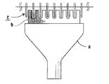
また、特開2005−273967号公報に記載されているように、蒸気を噴射することによって熱交換器を洗浄するものとして、洗浄用の蒸気を生成する蒸気生成装置と、蒸気生成装置に装着される図7に示すようなカバーノズルaと、カバーノズルaの先端面から突出したブラシbとで構成され、このカバーノズルaにより、蒸気生成装置の噴出口から噴出される蒸気の周囲への拡散を規制するとともに、洗浄部位に効果的に集中させて蒸気を噴出させ、ブラシbは、ブラシ長さが異なる凸部と凹部とが繰り返された櫛歯状に形成されることで、ブラシbはフィンcに摺接して汚れを落とすものが知られている(例えば、特許文献2参照。)。 Further, as described in Japanese Patent Application Laid-Open No. 2005-273967, a steam generator that generates cleaning steam, and a steam generator that are mounted on the steam generator are designed to clean the heat exchanger by injecting steam. 7 is composed of a cover nozzle a as shown in FIG. 7 and a brush b protruding from the front end surface of the cover nozzle a, and by this cover nozzle a, diffusion of the steam ejected from the ejection port of the steam generating device to the surroundings The brush b is formed in a comb-like shape in which convex portions and concave portions having different brush lengths are repeated, so that the brush b is A device that slides on the fin c to remove dirt is known (for example, see Patent Document 2).
このものにおいて、熱交換器を洗浄する洗浄用の蒸気(水)をどのように供給するかという問題点を有していた。 However, this method has a problem of how to supply cleaning steam (water) for cleaning the heat exchanger.
また、特開平11−103936号公報に記載されているように、図8に示すような基板aと、この基板aの一方向に複数列に配置させた毛群bと、前記基板aの他方面に設けられた把持部cとを具備し、前記毛群bをフィンF,F相互間に最大限に挿入した状態において、前記毛群bの先端が管Pの配設エリアにとどく長さに設定した手動ブラシBを用いることによって熱交換器RGを清掃するものが知られている(例えば、特許文献3参照。)。 Further, as described in JP-A No. 11-103936, a substrate a as shown in FIG. 8, a hair group b arranged in a plurality of rows in one direction of the substrate a, and the substrate a A grip portion c provided in the direction, and the length of the bristles b reaches the area where the tube P is disposed in a state where the bristles b are inserted between the fins F and F to the maximum. What cleans the heat exchanger RG by using the manual brush B set to 1 is known (for example, refer patent document 3).
このものにおいて、室外機の設置位置によっては、手動ブラシBを用いて熱交換器RGを清掃することができず、また、手作業によって清掃できるとしても、熱交換器RGから除去した塵埃を自動的に外部に排出することができないという問題点を有していた。
そこで、本発明は上述した課題を解決するためになされたものであって、空気流の圧力損失を増加させずに熱交換器を自動的に清掃できるようにし、停止時には外部からの汚れが付着しないようにした清掃ユニットを備えた空気調和機の室外機を提供することを目的とする。 Therefore, the present invention has been made to solve the above-described problems, and enables the heat exchanger to be automatically cleaned without increasing the pressure loss of the air flow. It aims at providing the outdoor unit of the air conditioner provided with the cleaning unit made to prevent.
上述した目的を達成するため、本発明は以下に示す特徴を備えている。 In order to achieve the above-described object, the present invention has the following features.
底板上に熱交換器および送風ファンが配置され、前記熱交換器に対向して同熱交換器を清掃する清掃ユニットが設けられ、前記底板に被着された外胴の上面部にフランジを備えた天板が被着されてなる空気調和機の室外機であって、
前記清掃ユニットが、前記熱交換器に当接するブラシを備えた清掃部と、同清掃部を上下に移動させる駆動部および移動可能に支持する支持部とを備えてなり、
前記清掃ユニットの清掃動作を停止した際、前記清掃部を前記フランジに対向するように位置させてなることを特徴としている。
A heat exchanger and a blower fan are disposed on the bottom plate, a cleaning unit for cleaning the heat exchanger is provided opposite to the heat exchanger, and a flange is provided on the upper surface portion of the outer cylinder attached to the bottom plate. An outdoor unit of an air conditioner with a top plate attached thereto,
The cleaning unit includes a cleaning unit including a brush that comes into contact with the heat exchanger, a drive unit that moves the cleaning unit up and down, and a support unit that supports the movement unit.
When the cleaning operation of the cleaning unit is stopped, the cleaning unit is positioned so as to face the flange.
また、前記清掃ユニットが、前記熱交換器の風下側に対向配置されてなることを特徴としている。 Further, the cleaning unit is arranged to face the leeward side of the heat exchanger.
また、前記底板上に、前記ブラシで取り除かれた塵埃を外部に排出する排出部が設けられてなることを特徴としている。 In addition, a discharge portion for discharging dust removed by the brush to the outside is provided on the bottom plate.
また、前記清掃ユニットの清掃動作が停止した後、前記送風ファンを所定時間駆動してなることを特徴としている。 Further, after the cleaning operation of the cleaning unit is stopped, the blower fan is driven for a predetermined time.
本発明によれば、空気流の圧力損失を増加させずに熱交換器を自動的に清掃できるようにし、停止時には外部からの汚れが付着しないようにした清掃ユニットを備えた空気調和機の室外機を提供できる。 According to the present invention, the heat exchanger can be automatically cleaned without increasing the pressure loss of the air flow, and the outdoor unit of the air conditioner including the cleaning unit that prevents dirt from the outside from adhering when stopped. Can provide a machine.
次に、本発明の実施形態について図面を参照しながら説明する。 Next, embodiments of the present invention will be described with reference to the drawings.
図1は本発明による空気調和機の室外機の内部構造を示す斜視図であり、図2は本発明による空気調和機の室外機の要部説明図で、図2(A)は斜視図、図2(B)は側面図であり、図3は本発明による空気調和機の室外機の要部説明図で、図3(A)は斜視図、図3(B)は図3(A)に示すA−A断面図の一例を、図3(C)は他の例を示す図であり、図4は本発明による空気調和機の室外機の要部説明図で、図4(A)は斜視図、図4(B)は側面図であり、図5は本発明による空気調和機の室外機の要部説明図で、図5(A)は分解斜視図、図5(B)は図5(A)に示すb矢視図である。 FIG. 1 is a perspective view showing an internal structure of an outdoor unit of an air conditioner according to the present invention, FIG. 2 is an explanatory view of a main part of the outdoor unit of the air conditioner according to the present invention, and FIG. 2 (B) is a side view, FIG. 3 is an explanatory view of a main part of an outdoor unit of an air conditioner according to the present invention, FIG. 3 (A) is a perspective view, and FIG. 3 (B) is FIG. 3 (A). FIG. 3 (C) is a diagram showing another example, and FIG. 4 is an explanatory view of the main part of the outdoor unit of the air conditioner according to the present invention, and FIG. 4 (A). Is a perspective view, FIG. 4 (B) is a side view, FIG. 5 is an explanatory view of a main part of an outdoor unit of an air conditioner according to the present invention, FIG. 5 (A) is an exploded perspective view, and FIG. It is b arrow line view shown to FIG. 5 (A).
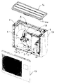
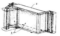
本発明による空気調和機の室外機は、図1に示すように、底板1の上部が、同底板1の上部に立設された仕切板2により圧縮機室と熱交換器室とに区画され、前記圧縮機室に圧縮機5が設けられるとともに、同圧縮機5の上部に電装部12が設けられ、前記熱交換器室に平面視でL字状に形成された熱交換器3と、同熱交換器3の長辺部に対向させた送風ファン4とが設けられている。
As shown in FIG. 1, an outdoor unit of an air conditioner according to the present invention has an upper portion of a
前記熱交換器3は、等間隔で平行に並べられた放熱用の多数のフィン3aと、これに直交して冷媒を流通させる伝熱管3bとからなる構成になっている。
The
前記底板1には、前記熱交換器3を臨ませて、同熱交換器3の風上側から外気を吸い込むための図示しない吸込口を備えた外胴13が被着されるとともに、前記外胴13の上面部は天板14が被着されることによってカバーされている。また、前記熱交換器3の風下側となる前記底板1には、図示しないファンモータを備えた前記送風ファン4が設けられ、同送風ファン4を臨ませた前面部には、前記熱交換器3で熱交換された空気を吐き出すための吐出口を構成する前面パネル15が設けられている。
An
すなわち、前記熱交換器3の風上側に外気を吸い込む吸込口が設けられ、同熱交換器3の風下側に、前記送風ファン4および熱交換された空気を吐き出す吐出口が設けられた構成になっている。
That is, a suction port for sucking outside air is provided on the windward side of the
前記底板1は、その四側に上方に立設したフランジ1aが一体的に成形されており、これによって強度が増強されるとともに、前記熱交換器3から滴下したドレン水が周囲に流出することなく、図示しない排水口に導かれて排水されるようになっている。
The
前記天板14は、その四側に下方に垂下したフランジ14aが一体的に成形されており、これによって強度が増強されるとともに、前記外胴13および前記前面パネル15の上端縁を前記フランジ14aに沿わせることで容易に、且つ正確に位置合わせすることができるようになっている。
The
前記熱交換器3は、前記吸込口から吸い込まれる外気中に含まれた塵埃の一部が付着することによって、同熱交換器3としての性能を低下させてしまうおそれがあることから、同熱交換器3に付着した塵埃を除去するための清掃ユニット6が移動可能に付設されている。
Since the
次に、前記清掃ユニット6の構成について、図2乃至図5に基づいて詳細に説明する。
Next, the configuration of the
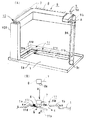
前記清掃ユニット6は、前記熱交換器3に当接させて、同熱交換器3を構成するフィン3aおよび伝熱管3bに付着した塵埃を取り除くブラシ7を備えた清掃部8と、同清掃部8を下方および上方に移動させる駆動部9と、下方および上方に移動可能に支持する支持部10とからなる構成になっている。
The
また、前記底板1には、前記ブラシ7の位置に対応して、同ブラシ7で取り除かれた塵埃を外部に排出する排出部11が設けられた構成になっている。
Further, the
前記排出部11は、前記底板1の一部を上方に膨出するように形成した膨出部1bに設けられており、これにより、前記熱交換器3から前記膨出部1bに滴下した凝縮水は、図2(B)に示す矢印eのように前記底板1上に流れて図示しない排水口に向かうようになる。
The
前記清掃部8に備えたブラシ7は、一例として図3(B)に示すように、弾力性に富む太ブラシ7aと柔軟性を有する細ブラシ7bとを組み合わせた構成にすることにより、前記フィン3aおよび前記伝熱管3bに付着した塵埃を効果的に取り除くことができるようになっている。
As an example, as shown in FIG. 3B, the
または、他の例として図3(C)に示すブラシ7’のように、矢印の方向に回転させながら下降させることによって、前記フィン3aおよび前記伝熱管3bに付着した塵埃を取り除くことができるようにしてもよい。
Alternatively, as another example, like the
前記駆動部9は、図2(A)と、図4(A)および図4(B)とに示すように、前記熱交換器3の上端部近傍に設けられ図示しない駆動モータを収容した駆動ケース9aと、同駆動ケース9a内の駆動モータに連結されたスプロケット9bと、前記底板1の近傍に設けられたプーリィ9cと、これらスプロケット9bおよびプーリィ9cの間に掛け渡されたベルト9dとで構成されている。
As shown in FIG. 2 (A), FIG. 4 (A), and FIG. 4 (B), the
前記ベルト9dには、取付部Aによって、前記スプロケット9bを図4(B)に示す矢印a’方向に駆動することで前記清掃部8が矢印aのように下降可能に、また、前記スプロケット9bを逆方向に駆動することで上昇可能になるように、前記清掃部8が取り付けられている。
The
前記清掃ユニット6は、前記熱交換器3の風下側となる内側のスペースであって前記送風ファン4側に設けられることで、室外機を大型化させることがないようにして、前記熱交換器3のフィン3aに沿って、前記清掃部8が上下方向に移動可能になる状態に構成されている。
The
これにより、前記ブラシ7は前記熱交換器3の風下側から対向させた構成で、同ブラシ7の先端部が平行に並べられた多数の前記フィン3aの間に深く入り込んで移動することにより、同フィン3aおよびこれに直交する前記伝熱管3bに付着した塵埃を取り除きながら、前記底板1の上部に集塵する機能を有している。
Thereby, the
前記駆動部9は、室外機または同室外機が接続された室内機の所定の積算運転時間毎に前記駆動モータを駆動し、前記ベルト9dに駆動力を伝達して、前記清掃部8および同清掃部8に備えたブラシ7を移動させるようにしている。
The
これによって、上述した所定の積算運転時間が経過する毎に、前記駆動部9によって移動させる前記清掃部8に備えたブラシ7で、前記熱交換器3のフィン3aおよび伝熱管3bに付着した塵埃を取り除くことができるようになる。
As a result, the dust adhered to the
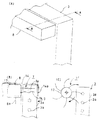
また、前記排出部11は、前記清掃ユニット6の清掃部8および同清掃部8に備えたブラシ7に対応して前記底板1に設けられ、前記清掃部8の下降時に開放し、上昇時に閉塞する枢支部11cを有する開閉蓋11bを備えた排出口11aからなる構成になっている。
The
前記清掃ユニット6の清掃部8および同清掃部8に備えたブラシ7が前記熱交換器3に付着した塵埃を取り除きながら、前記熱交換器3の下端部近傍に下降した際、前記開閉蓋11bを開かせることによって、前記ブラシ7で取り除いた塵埃を前記排出口11aから外部に排出できるようになる。
When the
また、前記清掃ユニット6の清掃部8が前記熱交換器3の下端部近傍に下降した後、清掃動作を停止して同熱交換器3の上端部近傍の所定位置に戻った際、前記送風ファン4を所定の時間駆動させるようにした構成になっている。
Further, when the
これによって、前記熱交換器3の表面にわずかに取り残されて、同熱交換器3から離脱しそうになっている塵埃を、前記送風ファン4によって前記吐出口から吐き出される吹出空気流といっしょに外部に吐き出せるようになる。
As a result, the dust that is slightly left on the surface of the
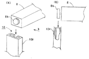
前記支持部10は、図5(A)および図5(B)に示すように、前記清掃ユニット6の清掃部8に設けられたガイドローラ8bを下方に、または上方に導くことができるローラガイド10aからなり、前記清掃部8を前記熱交換器3に沿って下降させ、または上昇させることができるように支持している。
As shown in FIGS. 5 (A) and 5 (B), the
なお、前記ガイドローラ8bは、小径部と大径部とを備えた構成になっており、前記ローラガイド10aは、前記小径部に対応するスリット部と、前記大径部を上下動可能に収容する収容部とを備えた構成になっている。
The
なお、前記清掃ユニット6の清掃部8は、清掃動作を停止して前記熱交換器3の上端部近傍の所定位置に停止した際、前記天板14およびその四側から垂下されたフランジ14aによってカバーされることから、前記吸込口から吸い込まれる外気が直接当たりにくくなって、前記熱交換器3に向かう空気流に対する空気抵抗になってしまうということがない。
When the
また、前記吸込口から吸い込まれる外気が直接当たらないので、外気中に含まれた塵埃が付着しにくいため汚れにくい構成になっている。 In addition, since the outside air sucked from the suction port does not directly hit, the dust contained in the outside air is difficult to adhere, so that it is difficult to get dirty.
次に、上述した清掃ユニット6の構成に基づいて、同清掃ユニット6の清掃動作について説明する。
Next, the cleaning operation of the
室外機および同室外機に接続された室内機の運転停止時および運転時で、前記熱交換器3の清掃を行なわない清掃動作の停止時に、前記清掃ユニット6は前記熱交換器3の上端部近傍の所定位置に停止している。
When the operation of the outdoor unit and the indoor unit connected to the outdoor unit is stopped and during operation, the
前記清掃ユニット6は、室外機および同室外機に接続された室内機の上述した所定の積算運転時間毎に、前記駆動部9によって駆動され前記熱交換器3に沿って下降した前記清掃部8に備えたブラシ7で、同熱交換器3に付着した塵埃を取り除くことになる。
The
前記開閉蓋11bは、図2(B)に示す矢印aのように、前記駆動部9によって駆動された前記清掃部8が下降した際、同清掃部8の下部に突設された押圧体8aで押圧されることにより、前記枢支部11cに設けられた付勢ばね11dによる矢印bに示す付勢力に抗して、矢印cのように下方に押し開かれることにより、前記排出口11aを開放して、同排出口11aから前記ブラシ7で取り除かれた前記熱交換器3に付着していた塵埃を、矢印dのように外部に排出する。
When the
前記熱交換器3から塵埃を取り除いた前記清掃部8は、清掃動作の停止時に、上方に移動して前記熱交換器3の上端部近傍の所定位置に停止するとともに、前記押圧体8aで前記開閉蓋11bが押圧されることによって開放されていた前記底板1の排出口11aは、前記付勢ばね11dによる付勢力により、前記枢支部11cを中心に回動する前記開閉蓋11bよって閉塞される。
The
前記清掃ユニット6の清掃部8が、清掃動作の停止時に前記熱交換器3の上端部近傍の所定位置に停止した後、前記送風ファン4が所定の時間駆動され、前記熱交換器3に取り残されていた塵埃を前記吐出口から吐き出した後に停止する。
After the
以上説明したように、本発明によれば、清掃動作の停止時に、前記清掃ユニット6の清掃部8が前記熱交換器3の上端部近傍の所定位置に停止した際、前記吸込口から吸い込まれる外気が直接当たりにくくなって、前記清掃ユニット6の清掃部8が、前記熱交換器3に向かう空気流に対する空気抵抗にならないので空気流の圧力損失が増加しないようになり、また、同清掃ユニット6の清掃部8に外部からの汚れが付着してしまうということがなくなる。
As described above, according to the present invention, when the cleaning operation of the
そして、上述した背景技術のように蒸気の噴射や手動ブラシによらずに、自動的に前記熱交換器3の清掃を行って、同熱交換器3から取り除いた塵埃を外部に排出できる清掃ユニット3を備えた空気調和機の室外機となる。
The cleaning unit can automatically clean the
1 底板
1a フランジ
1b 膨出部
2 仕切板
3 熱交換器
3a フィン
3b 伝熱管
4 送風ファン
5 圧縮機
6 清掃ユニット
7 ブラシ
7a 太ブラシ
7b 細ブラシ
8 清掃部
8a 押圧体
8b ガイドローラ
9 駆動部
9a ケース
9b スプロケット
9c プーリィ
9d ベルト
10 支持部
10a ローラガイド
11 排出部
11a 排出口
11b 開閉蓋
11c 枢支部
11d 付勢ばね
12 電装部
13 外胴
14 天板
14a フランジ
15 前面パネル
DESCRIPTION OF
Claims (4)
前記清掃ユニットが、前記熱交換器に当接するブラシを備えた清掃部と、同清掃部を上下に移動させる駆動部および移動可能に支持する支持部とを備えてなり、
前記清掃ユニットの清掃動作を停止した際、前記清掃部を前記フランジに対向するように位置させてなることを特徴とする空気調和機の室外機。 A heat exchanger and a blower fan are disposed on the bottom plate, a cleaning unit for cleaning the heat exchanger is provided opposite to the heat exchanger, and a flange is provided on the upper surface portion of the outer cylinder attached to the bottom plate. An outdoor unit of an air conditioner with a top plate attached thereto,
The cleaning unit includes a cleaning unit including a brush that comes into contact with the heat exchanger, a drive unit that moves the cleaning unit up and down, and a support unit that supports the movement unit.
An outdoor unit for an air conditioner, wherein the cleaning unit is positioned so as to face the flange when the cleaning operation of the cleaning unit is stopped.
Priority Applications (1)
| Application Number | Priority Date | Filing Date | Title |
|---|---|---|---|
| JP2007172788A JP4872831B2 (en) | 2007-06-29 | 2007-06-29 | Air conditioner outdoor unit |
Applications Claiming Priority (1)
| Application Number | Priority Date | Filing Date | Title |
|---|---|---|---|
| JP2007172788A JP4872831B2 (en) | 2007-06-29 | 2007-06-29 | Air conditioner outdoor unit |
Publications (2)
| Publication Number | Publication Date |
|---|---|
| JP2009008366A true JP2009008366A (en) | 2009-01-15 |
| JP4872831B2 JP4872831B2 (en) | 2012-02-08 |
Family
ID=40323612
Family Applications (1)
| Application Number | Title | Priority Date | Filing Date |
|---|---|---|---|
| JP2007172788A Expired - Fee Related JP4872831B2 (en) | 2007-06-29 | 2007-06-29 | Air conditioner outdoor unit |
Country Status (1)
| Country | Link |
|---|---|
| JP (1) | JP4872831B2 (en) |
Cited By (7)
| Publication number | Priority date | Publication date | Assignee | Title |
|---|---|---|---|---|
| CN102962214A (en) * | 2012-12-05 | 2013-03-13 | 四川长虹空调有限公司 | Dust removal mechanism for heat exchanger of air conditioner outdoor unit |
| CN104197431A (en) * | 2014-08-29 | 2014-12-10 | 美的集团武汉制冷设备有限公司 | Outdoor unit of air conditioner |
| CN105674478A (en) * | 2016-01-04 | 2016-06-15 | 广东美的暖通设备有限公司 | Air conditioner and cleaning method for condenser of air conditioner |
| CN110195915A (en) * | 2019-05-03 | 2019-09-03 | 浙江维大师网络科技有限公司 | Fault detection means based on air-conditioning maintenance |
| JP2019200023A (en) * | 2018-05-18 | 2019-11-21 | サンデン・リテールシステム株式会社 | Show case |
| CN112810405A (en) * | 2021-01-19 | 2021-05-18 | 毕建娜 | Vehicle-mounted refrigerator for cold chain logistics |
| CN114636260A (en) * | 2022-03-15 | 2022-06-17 | 徐紫莉 | Air conditioner condenser |
Citations (5)
| Publication number | Priority date | Publication date | Assignee | Title |
|---|---|---|---|---|
| JPS44695Y1 (en) * | 1965-11-12 | 1969-01-13 | ||
| JPS4846263A (en) * | 1971-10-13 | 1973-07-02 | ||
| JPS5429560Y2 (en) * | 1974-09-06 | 1979-09-19 | ||
| JPH02109189A (en) * | 1988-10-18 | 1990-04-20 | Koufu Nippon Denki Kk | Audio response ic card |
| JPH02127988A (en) * | 1988-11-07 | 1990-05-16 | Hitachi Ltd | Laser beam marking device |
-
2007
- 2007-06-29 JP JP2007172788A patent/JP4872831B2/en not_active Expired - Fee Related
Patent Citations (5)
| Publication number | Priority date | Publication date | Assignee | Title |
|---|---|---|---|---|
| JPS44695Y1 (en) * | 1965-11-12 | 1969-01-13 | ||
| JPS4846263A (en) * | 1971-10-13 | 1973-07-02 | ||
| JPS5429560Y2 (en) * | 1974-09-06 | 1979-09-19 | ||
| JPH02109189A (en) * | 1988-10-18 | 1990-04-20 | Koufu Nippon Denki Kk | Audio response ic card |
| JPH02127988A (en) * | 1988-11-07 | 1990-05-16 | Hitachi Ltd | Laser beam marking device |
Cited By (8)
| Publication number | Priority date | Publication date | Assignee | Title |
|---|---|---|---|---|
| CN102962214A (en) * | 2012-12-05 | 2013-03-13 | 四川长虹空调有限公司 | Dust removal mechanism for heat exchanger of air conditioner outdoor unit |
| CN104197431A (en) * | 2014-08-29 | 2014-12-10 | 美的集团武汉制冷设备有限公司 | Outdoor unit of air conditioner |
| CN105674478A (en) * | 2016-01-04 | 2016-06-15 | 广东美的暖通设备有限公司 | Air conditioner and cleaning method for condenser of air conditioner |
| JP2019200023A (en) * | 2018-05-18 | 2019-11-21 | サンデン・リテールシステム株式会社 | Show case |
| JP7058174B2 (en) | 2018-05-18 | 2022-04-21 | サンデン・リテールシステム株式会社 | Showcase |
| CN110195915A (en) * | 2019-05-03 | 2019-09-03 | 浙江维大师网络科技有限公司 | Fault detection means based on air-conditioning maintenance |
| CN112810405A (en) * | 2021-01-19 | 2021-05-18 | 毕建娜 | Vehicle-mounted refrigerator for cold chain logistics |
| CN114636260A (en) * | 2022-03-15 | 2022-06-17 | 徐紫莉 | Air conditioner condenser |
Also Published As
| Publication number | Publication date |
|---|---|
| JP4872831B2 (en) | 2012-02-08 |
Similar Documents
| Publication | Publication Date | Title |
|---|---|---|
| JP4872831B2 (en) | Air conditioner outdoor unit | |
| AU2006317267B2 (en) | Air conditioning apparatus | |
| KR101148752B1 (en) | Indoor unit for air conditioner | |
| WO2010143230A1 (en) | Air conditioner | |
| JP2007263412A (en) | Cleaning device of air conditioner, and air conditioner | |
| JP3923067B2 (en) | Air conditioner | |
| CN207527817U (en) | Air-conditioning filter device | |
| JP2008002767A (en) | Indoor unit of air conditioner | |
| WO2006043430A1 (en) | Air conditioner | |
| JP2004156794A (en) | Air conditioner | |
| JP5215128B2 (en) | Air conditioner | |
| JP2006183996A (en) | Air conditioner | |
| JP2008045858A (en) | Cleaning body for air conditioner, and air conditioner | |
| JP2009014265A (en) | Outdoor unit of air conditioner | |
| JP4269141B2 (en) | Air conditioner | |
| JP4878521B2 (en) | Air conditioner indoor unit | |
| CN100338399C (en) | Air conditioner having indoor unit with automatic air filter-cleaning function | |
| JP2008045822A (en) | Indoor unit of air conditioner | |
| JP4134768B2 (en) | Air conditioner | |
| JP5092409B2 (en) | Air conditioner | |
| KR20090044786A (en) | Air conditioner | |
| JP2008039324A (en) | Indoor unit of air conditioner | |
| JP2006105591A (en) | Filter device for air-conditioner | |
| JP2006022982A (en) | Dust removing apparatus, and air conditioner using the same | |
| CN101057110A (en) | Air conditioner |
Legal Events
| Date | Code | Title | Description |
|---|---|---|---|
| A621 | Written request for application examination |
Free format text: JAPANESE INTERMEDIATE CODE: A621 Effective date: 20090630 |
|
| A977 | Report on retrieval |
Free format text: JAPANESE INTERMEDIATE CODE: A971007 Effective date: 20110524 |
|
| A131 | Notification of reasons for refusal |
Free format text: JAPANESE INTERMEDIATE CODE: A131 Effective date: 20110607 |
|
| A521 | Written amendment |
Free format text: JAPANESE INTERMEDIATE CODE: A523 Effective date: 20110808 |
|
| TRDD | Decision of grant or rejection written | ||
| A01 | Written decision to grant a patent or to grant a registration (utility model) |
Free format text: JAPANESE INTERMEDIATE CODE: A01 Effective date: 20111025 |
|
| A01 | Written decision to grant a patent or to grant a registration (utility model) |
Free format text: JAPANESE INTERMEDIATE CODE: A01 |
|
| A61 | First payment of annual fees (during grant procedure) |
Free format text: JAPANESE INTERMEDIATE CODE: A61 Effective date: 20111107 |
|
| FPAY | Renewal fee payment (event date is renewal date of database) |
Free format text: PAYMENT UNTIL: 20141202 Year of fee payment: 3 |
|
| R151 | Written notification of patent or utility model registration |
Ref document number: 4872831 Country of ref document: JP Free format text: JAPANESE INTERMEDIATE CODE: R151 |
|
| FPAY | Renewal fee payment (event date is renewal date of database) |
Free format text: PAYMENT UNTIL: 20141202 Year of fee payment: 3 |
|
| S531 | Written request for registration of change of domicile |
Free format text: JAPANESE INTERMEDIATE CODE: R313532 |
|
| R350 | Written notification of registration of transfer |
Free format text: JAPANESE INTERMEDIATE CODE: R350 |
|
| LAPS | Cancellation because of no payment of annual fees |