JP2009007780A - Hair catcher - Google Patents

Hair catcher Download PDF

Info

Publication number
JP2009007780A
JP2009007780A JP2007168215A JP2007168215A JP2009007780A JP 2009007780 A JP2009007780 A JP 2009007780A JP 2007168215 A JP2007168215 A JP 2007168215A JP 2007168215 A JP2007168215 A JP 2007168215A JP 2009007780 A JP2009007780 A JP 2009007780A
Authority
JP
Japan
Prior art keywords
hair catcher
drainage
hair
drainage inflow
protrusion
Prior art date
Legal status (The legal status is an assumption and is not a legal conclusion. Google has not performed a legal analysis and makes no representation as to the accuracy of the status listed.)
Withdrawn
Application number
JP2007168215A
Other languages
Japanese (ja)
Inventor
Koichi Matsumura
浩一 松村
Current Assignee (The listed assignees may be inaccurate. Google has not performed a legal analysis and makes no representation or warranty as to the accuracy of the list.)
Panasonic Electric Works Co Ltd
Original Assignee
Panasonic Electric Works Co Ltd
Priority date (The priority date is an assumption and is not a legal conclusion. Google has not performed a legal analysis and makes no representation as to the accuracy of the date listed.)
Filing date
Publication date
Application filed by Panasonic Electric Works Co Ltd filed Critical Panasonic Electric Works Co Ltd
Priority to JP2007168215A priority Critical patent/JP2009007780A/en
Publication of JP2009007780A publication Critical patent/JP2009007780A/en
Withdrawn legal-status Critical Current

Links

Images

Landscapes

  • Sink And Installation For Waste Water (AREA)

Abstract

<P>PROBLEM TO BE SOLVED: To provide a hair catcher, allowing a user to reduce the number of times cleaning by increasing the efficiency of catching hair when draining water, and having an excellent clogging prevention function. <P>SOLUTION: This hair catcher 50 is constituted by opening a drainage inflow part 2 for letting drainage flow in from the fixed direction A on one side face 1b of a drainage cover part 1 covering a drain hole 7 in a floor pan 9, attaching a hair catcher body 3 to a section below the drainage cover part 1 detachably, providing many water drain holes 4 and many projections 5 protruding upward from a surface 3a of the hair catcher body in the hair catcher body 3, and tilting one face 5a opposing to the drainage inflow part 2 of the projection 5 toward a drainage inflow part 2 side at an acute angle. <P>COPYRIGHT: (C)2009,JPO&INPIT

Description

本発明は、ユニットバスルーム等の床パンの排水孔に取り付けられるヘアキャッチャーに関するものである。   The present invention relates to a hair catcher attached to a drain hole of a floor pan such as a unit bathroom.

従来から、ユニットバスルーム等の床パンの排水孔に多数の流水孔を備えた目皿(ヘアキャッチャー)を着脱自在に取り付けた構造が知られている(例えば、特許文献1参照)。   2. Description of the Related Art Conventionally, there has been known a structure in which an eye plate (hair catcher) having a large number of water flow holes is detachably attached to drain holes of a floor pan such as a unit bathroom (for example, see Patent Document 1).

ところが上記特許文献1に示される従来例にあっては、目皿の多数の流水孔が毛髪で目詰まりしやすくなり、掃除の回数が増えるという問題があり、また、目皿を取り外して掃除する際には、毛髪が目皿の流水孔に詰まって除去しにくいものであり、このため楽に清掃することができないという問題もあった。
特開2001−65025号公報
However, in the conventional example shown in Patent Document 1, there are problems that a large number of water holes in the eye plate are easily clogged with hair, and the number of times of cleaning increases, and the eye plate is removed and cleaned. In some cases, the hair clogs the running water holes of the eye plate and is difficult to remove, and therefore there is a problem that it cannot be easily cleaned.
JP 2001-65025 A

本発明は上記の従来の問題点に鑑みて発明したものであって、排水時に毛髪の捕捉効率を高めることができ、掃除の回数を減らすことができると共に目詰まり防止機能に優れたヘアキャッチャーを提供することを課題とし、また、掃除の際には毛髪を簡単に除去できるヘアキャッチャーを提供することを課題とするものである。   The present invention has been invented in view of the above-described conventional problems, and can improve the efficiency of capturing hair during drainage, reduce the number of cleanings, and provide a hair catcher that has an excellent clogging prevention function. It is an object to provide a hair catcher that can easily remove hair during cleaning.

前記課題を解決するために本発明は、床パン9の排水孔7を覆う排水カバー部1の一側面1bに排水を一定方向Aから流入させる排水流入部2を開口し、排水カバー部1の下方にヘアキャッチャー本体3を着脱自在に取り付け、ヘアキャッチャー本体3には、多数の水抜き穴4と、ヘアキャッチャー本体表面3aから上方に突出する多数の突起物5とが設けられ、上記突起物5の上記排水流入部2と対向する片面5aを排水流入部2側に向かって且つヘアキャッチャー本体表面3aに対して鋭角θ1に傾斜させたことを特徴としている。   In order to solve the above-mentioned problem, the present invention opens a drainage inflow portion 2 for allowing drainage to flow from a certain direction A into one side surface 1b of the drainage cover portion 1 that covers the drainage hole 7 of the floor pan 9. The hair catcher body 3 is detachably attached to the lower side, and the hair catcher body 3 is provided with a number of drain holes 4 and a number of projections 5 protruding upward from the hair catcher body surface 3a. 5 is inclined at an acute angle θ1 toward the drainage inflow portion 2 side and with respect to the hair catcher body surface 3a.

このような構成とすることで、排水カバー部1の排水流入部2からヘアキャッチャー本体3への排水流れが一定方向Aとなり、多数の突起物5のそれぞれの片面5aに排水が当たるようになる。このとき、排水中に含まれる毛髪6が突起物5の鋭角θ1に傾斜した片面5aに誘い込まれて捕らえられると共に、排水の流勢によって突起物5から外れてしまうことがない。従って、突起物5による毛髪捕捉効率が向上して、水抜き穴4の目詰まりを防止できるようになる。   With such a configuration, the drainage flow from the drainage inflow portion 2 of the drainage cover portion 1 to the hair catcher main body 3 is in a fixed direction A, and the drainage comes into contact with each one surface 5a of the many protrusions 5. . At this time, the hair 6 contained in the waste water is attracted to and captured by the one surface 5a inclined at the acute angle θ1 of the protrusion 5 and is not detached from the protrusion 5 due to the flow of the waste water. Therefore, the hair capturing efficiency by the protrusions 5 is improved, and clogging of the drain holes 4 can be prevented.

また、上記突起物5の排水流入部2と対向する片面5aとは反対側の背面5bを、該片面5aの傾斜方向と同方向に向かって且つヘアキャッチャー本体表面3aに対して鈍角θ2に傾斜させるのが好ましく、この場合、ヘアキャッチャー本体3を取り外して掃除する際に、多数の突起物5の片面5aとは反対側の背面5b側から例えばシャワー水を当てることにより、突起物5の片面5a側に捕らえられた毛髪が背面5b側からの水流によって外れやすくなり、簡単に洗い流せるようになる。   Further, the back surface 5b opposite to the one surface 5a facing the drainage inflow portion 2 of the protrusion 5 is inclined in the same direction as the inclination direction of the one surface 5a and at an obtuse angle θ2 with respect to the hair catcher body surface 3a. In this case, when removing the hair catcher body 3 for cleaning, for example, shower water is applied from the side of the back surface 5b opposite to the one surface 5a of the many protrusions 5 to thereby provide one surface of the protrusion 5 The hair captured on the 5a side is easily detached by the water flow from the back surface 5b side, and can be easily washed away.

また、上記隣り合う突起物5と突起物5との間に水抜き穴4を配置するのが好ましく、この場合、水抜き穴4の両側に突起物5が位置することで、水抜き穴4から流れ落ちようとする毛髪を突起物5で効率よく捕らえることができる。   Moreover, it is preferable to arrange the drainage hole 4 between the adjacent projections 5, and in this case, the projections 5 are located on both sides of the drainage hole 4, so that the drainage hole 4 is disposed. It is possible to efficiently capture the hair that is about to flow down from the protrusion 5 with the protrusions 5.

請求項1記載の発明は、排水カバー部の排水流入部からヘアキャッチャー本体への排水流れを一定方向に整流すると共に、ヘアキャッチャー本体表面から多数の突起物の片面を排水流入部側に向かって鋭角に傾斜させたことにより、排水時に毛髪を捕捉しやすくなり、結果、ヘアキャッチャー本体の掃除の回数を減らすことができると共に目詰まり防止効果を高めることができる。   The invention described in claim 1 rectifies the drainage flow from the drainage inflow part of the drainage cover part to the hair catcher body in a certain direction, and directs one side of many protrusions from the surface of the haircatcher body toward the drainage inflow part side. By inclining at an acute angle, it becomes easier to capture hair during drainage, and as a result, the number of cleanings of the hair catcher body can be reduced and the effect of preventing clogging can be enhanced.

請求項2記載の発明は、突起物の背面を鈍角に傾斜させたことにより、ヘアキャッチャー本体を取り外して掃除する際に、多数の突起物の片面とは反対側の背面側からシャワー水を当てるだけで、突起物から毛髪を簡単に除去でき、掃除がしやすくなる。   In the invention according to claim 2, when the back surface of the projection is inclined at an obtuse angle, when removing the hair catcher main body and cleaning it, shower water is applied from the back side opposite to one side of many projections. The hair can be easily removed from the protrusions, and cleaning is easy.

請求項3記載の発明は、隣り合う突起物と突起物との間に水抜き穴を配置することにより、毛髪捕捉効率をより高めることができる。   In the invention according to the third aspect, the hair catching efficiency can be further improved by disposing a drain hole between the adjacent protrusions.

以下、本発明を添付図面に示す実施形態に基いて説明する。   Hereinafter, the present invention will be described based on embodiments shown in the accompanying drawings.

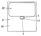
図1は本実施形態のヘアキャッチャー50の取り付け状態の一例を示し、図2はヘアキャッチャー50が取り付けられる浴室の取付口17の配置例を示す概略平面図である。   FIG. 1 shows an example of the attachment state of the hair catcher 50 of the present embodiment, and FIG. 2 is a schematic plan view showing an arrangement example of the attachment port 17 of the bathroom to which the hair catcher 50 is attached.

浴室の床パン9は、洗い場を構成する洗い場部10と浴槽が設置される浴槽設置部22とを備えており、洗い場部10と浴槽設置部22の間には堰部12を立ち上げている。床パン9の浴槽設置部22側の端部には取付口17を形成してあり、取付口17に排水トラップ13を取り付けることで排水孔7を形成している。   The bathroom floor pan 9 includes a washing place 10 that constitutes a washing place and a bathtub setting part 22 in which a bathtub is placed, and a weir part 12 is raised between the washing place 10 and the bathtub setting part 22. . An attachment port 17 is formed at the end of the floor pan 9 on the bathtub installation part 22 side, and the drain hole 7 is formed by attaching the drain trap 13 to the attachment port 17.

排水トラップ13は、図1に示すように、取付口17の下方に配置される容器状のトラップ本体14と、トラップ本体14に取り付けた取付用筒体15と、トラップ本体14の内側に挿入される封水筒体16とを備えている。   As shown in FIG. 1, the drain trap 13 is inserted into a container-like trap body 14 disposed below the attachment port 17, a mounting cylinder 15 attached to the trap body 14, and the inside of the trap body 14. The sealed water cylinder 16 is provided.

トラップ本体14の上面に形成した開口部18には取付用筒体15の下部をねじ込んで取り付けてあり、この取付用筒体15の上端部外周から突設した上側鍔部とトラップ本体14の開口部18の周縁部とでパッキン19を介して取付口17の周縁部を挟持して、トラップ本体14を水密的に取付口17に取り付けている。取付口17の周縁部は、排水カバー部1を配置するための凹所20を有している。取付用筒体15の下端部内周からは下側鍔部15aを突設してあり、下側鍔部15a上には封水筒体16の上端部に周設したフランジ部16aを載設している。   The lower part of the mounting cylinder 15 is screwed into the opening 18 formed on the upper surface of the trap body 14, and the upper flange projecting from the outer periphery of the upper end of the mounting cylinder 15 and the opening of the trap body 14. The trap body 14 is attached to the attachment port 17 in a watertight manner by sandwiching the periphery of the attachment port 17 with the peripheral edge of the part 18 via the packing 19. The peripheral edge portion of the attachment port 17 has a recess 20 for arranging the drainage cover portion 1. A lower flange 15a is provided so as to project from the inner periphery of the lower end of the mounting cylinder 15, and a flange 16a provided around the upper end of the sealed cylinder 16 is placed on the lower flange 15a. Yes.

なお図1中の8はオーバーフロー孔部8aを備えた第2のヘアキャッチャー、24は浴槽から排出された水をトラップ本体14内へと導く連通口部、22は排出口部、23は排水管である。   In FIG. 1, 8 is a second hair catcher having an overflow hole 8a, 24 is a communication port for guiding water discharged from the bathtub into the trap body 14, 22 is a discharge port, and 23 is a drain pipe. It is.

ここで、本発明のヘアキャッチャー50は、排水カバー部1とヘアキャッチャー本体3とで構成される。   Here, the hair catcher 50 of the present invention includes the drain cover portion 1 and the hair catcher body 3.

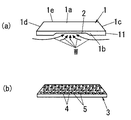
排水カバー部1は、図3(a)に示すように、平面視四角形状に形成され、その四周の外周部から下方に垂下した脚部11を有しており、排水カバー部1の上面を床パン9の洗い場部10と略面一とした状態で、脚部11がヘアキャッチャー本体3の外周部の上面に載置されている。脚部11の四周の側面1b〜1eのうち、洗い場床パンに面した一側面1bのみに切欠状の排水流入部2が形成されており、他の側面1c〜1eにはそれぞれ排水流入部は設けられず、従って、排水は凹所20の隙間25から排水流入部2を介して一定方向A(図1)から流入するようになっている。なお図3(a)中のWは排水流れの方向を示す。   As shown in FIG. 3A, the drainage cover portion 1 is formed in a square shape in plan view, and has a leg portion 11 that hangs downward from the outer periphery of the four circumferences. The leg portion 11 is placed on the upper surface of the outer peripheral portion of the hair catcher main body 3 in a state of being substantially flush with the washing place portion 10 of the floor pan 9. Of the four side surfaces 1b to 1e of the leg part 11, a notch-shaped drainage inflow portion 2 is formed only on one side surface 1b facing the washing floor floor pan, and the drainage inflow portions are respectively formed on the other side surfaces 1c to 1e. Accordingly, the drainage flows from the gap 25 of the recess 20 through the drainage inflow portion 2 from a certain direction A (FIG. 1). In addition, W in Fig.3 (a) shows the direction of a waste_water | drain flow.

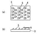
上記排水カバー部1の下方に配置されるヘアキャッチャー本体3は、図3(b)に示すように、排水カバー部1と同じ平面視四角形状に形成されており、その外周部が図1に示す取付口17の周縁部よりも一段高くなった凹所20の底部に載置されている。ヘアキャッチャー本体3には、図4(a)、(b)に示すように、多数の水抜き穴4が縦横に等間隔をあけて穿孔されていると共に、これら水抜き穴4を塞がないようにして、ヘアキャッチャー本体表面3aから上方に向けて多数の突起物5が突設されている。図4の例では、各突起物5の平面視形状及び側面視形状はいずれも三角形状をしている。   As shown in FIG. 3B, the hair catcher main body 3 disposed below the drain cover portion 1 is formed in the same square shape as the drain cover portion 1, and its outer peripheral portion is shown in FIG. It is placed on the bottom of the recess 20 which is one step higher than the peripheral edge of the mounting port 17 shown. As shown in FIGS. 4A and 4B, the hair catcher body 3 is provided with a number of drain holes 4 at equal intervals in the vertical and horizontal directions, and does not block the drain holes 4. In this way, a large number of protrusions 5 project from the hair catcher body surface 3a upward. In the example of FIG. 4, the planar view shape and the side view shape of each protrusion 5 are both triangular.

ここで、上記多数の突起物5は、図4(c)に示すように、上記排水流入部2側(図4(a)の右側)と対向する片面5aが、排水流入部2側に向かってそれぞれ傾斜していると共に、この傾斜角度はヘアキャッチャー本体表面3aに対して鋭角θ1となっている。また本例の突起物5の毛髪捕捉効果をより高めるために、隣り合う突起物5と突起物5との間に水抜き穴4が配置されている。さらにヘアキャッチャー本体3の掃除を容易に行なえるようにするために、図4(c)に示すように、各突起物5の排水流入部2側と対向する片面5aとは反対側の背面5bを、それぞれ、該片面5aの傾斜方向と同方向に向かって且つヘアキャッチャー本体表面3aに対して鈍角θ2に傾斜させてある。   Here, as shown in FIG. 4 (c), the one projection 5a facing the drainage inflow portion 2 side (the right side of FIG. 4 (a)) faces the drainage inflow portion 2 side. The inclination angle is an acute angle θ1 with respect to the hair catcher body surface 3a. Further, in order to further enhance the hair capturing effect of the protrusion 5 of this example, a drain hole 4 is disposed between the adjacent protrusions 5. Further, in order to facilitate the cleaning of the hair catcher main body 3, as shown in FIG. 4C, the back surface 5b opposite to the one surface 5a facing the drainage inflow portion 2 side of each projection 5 is provided. Are inclined in the same direction as the inclination direction of the one surface 5a and at an obtuse angle θ2 with respect to the hair catcher body surface 3a.

しかして、排水カバー部1の排水流入部2からヘアキャッチャー本体3への排水流れを一定方向Aに整流すると共に、ヘアキャッチャー本体表面3aから突出する多数の突起物5の片面5aを排水流入部2側に向かって鋭角θ1に傾斜させたことにより、排水時には図5(a)(b)のように毛髪が突起物5の片面5aに誘い込まれて引っ掛かりやすくなると共に、排水の流勢によって突起物5から外れてしまうことがない。また本例では、突起物5の先端が尖っているので、毛髪6を捕らえやすく、そのうえ隣り合う突起物5と突起物5との間に水抜き穴4を配置しているので、水抜き穴4の両側に突起物5が位置することによって、水抜き穴4から流れ落ちようとする毛髪を両側の突起物5で効率よく捕らえることができ、結果、毛髪捕捉効率が高められ、ヘアキャッチャー本体3の掃除の回数を減らすことができると共に目詰まり防止機能に優れたものとなる。   Thus, the drainage flow from the drainage inflow part 2 of the drainage cover part 1 to the hair catcher main body 3 is rectified in a fixed direction A, and one side 5a of a large number of protrusions 5 protruding from the haircatcher main body surface 3a is discharged into the drainage inflow part. By inclining at an acute angle θ1 toward the 2 side, the hair is attracted to one side 5a of the protrusion 5 and easily caught during drainage, as shown in FIGS. 5 (a) and 5 (b). It will not come off the protrusion 5. Moreover, in this example, since the front-end | tip of the protrusion 5 is sharp, it is easy to catch the hair 6, and since the drain hole 4 is arrange | positioned between the adjacent protrusion 5 and the protrusion 5, the drain hole Since the protrusions 5 are located on both sides of the hair 4, the hair that is about to flow down from the drain hole 4 can be efficiently captured by the protrusions 5 on both sides. As a result, the hair catching efficiency is increased, and the hair catcher body 3 The number of cleanings can be reduced and the clogging prevention function is excellent.

また本例では、ヘアキャッチャー本体3を取り外して掃除する際に、図6に示すように、多数の突起物5の片面5aとは反対側の背面5b側から例えばシャワー水を当てることにより、突起物5の片面5a側に絡んで引っ掛かっている毛髪が背面5b側からの水流Bによって外れやすくなり、簡単に洗い流せるので、掃除がしやすくなる効果もある。   Further, in this example, when the hair catcher body 3 is removed and cleaned, as shown in FIG. 6, for example, shower water is applied from the back surface 5 b side opposite to the one surface 5 a of the protrusions 5, thereby Since the hair entangled and caught on the one surface 5a side of the object 5 is easily detached by the water flow B from the back surface 5b side and can be easily washed away, there is also an effect that cleaning becomes easy.

上記水抜き穴4と突起物5との配置例は、図4に限定されるものではなく、例えば図7のように、排水流入部2側(図7(a)の右側)からみて、水抜き穴4の後方に突起物5がそれぞれ位置すると共に、前列の水抜き穴4及び突起物5を、後列の水抜き穴4及び突起物5に対して左右にずらして配置するようにしてもよい。   The arrangement example of the drain holes 4 and the projections 5 is not limited to FIG. 4. For example, as shown in FIG. The protrusions 5 are positioned behind the drain holes 4, and the front drain holes 4 and the protrusions 5 are arranged to be shifted left and right with respect to the rear drain holes 4 and the protrusions 5. Good.

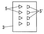
また多数の突起物5の平面視形状は三角形状に限らず、例えば先端が尖っていない台形状であってもよく、また図8に示すように、三角形状の突起物5と台形状の突起物5’とを組み合わせたものであってもよい。なお図8では水抜き穴4の図示は省略している。   Moreover, the planar view shape of the many protrusions 5 is not limited to a triangular shape, and may be, for example, a trapezoidal shape with a sharp tip, and as shown in FIG. 8, the triangular protrusion 5 and the trapezoidal protrusion It may be a combination of the object 5 ′. In addition, illustration of the drain hole 4 is abbreviate | omitted in FIG.

また図1の実施形態では、ヘアキャッチャー本体3の取り付け位置を床パン9の取付口17の凹所20としたが、これには限らず、例えば図9のように取付用筒体15の上側つば部15bの上面に載置したり、或いは図10のように封水筒体16のフランジ部16aの上面に載置して、ヘアキャッチャー本体3が第2のヘアキャッチャー8(図1)を兼ねる構造としてもよいものである。   In the embodiment of FIG. 1, the mounting position of the hair catcher body 3 is the recess 20 of the mounting opening 17 of the floor pan 9, but is not limited to this, for example, the upper side of the mounting cylinder 15 as shown in FIG. 9. The hair catcher body 3 also serves as the second hair catcher 8 (FIG. 1) by placing it on the top surface of the collar portion 15b or placing it on the top surface of the flange portion 16a of the sealed water cylinder 16 as shown in FIG. It may be a structure.

また前記各実施形態のヘアキャッチャー本体3に把手を設けて取り外しが簡単にできるようにしてもよい。   Moreover, a handle may be provided in the hair catcher main body 3 of each embodiment so that the hair catcher body 3 can be easily removed.

本発明の一実施形態のヘアキャッチャーの取り付け状態の一例を示す側面断面図である。It is side surface sectional drawing which shows an example of the attachment state of the hair catcher of one Embodiment of this invention. 同上のヘアキャッチャーが取り付けられる取付口を説明する浴室の概略平面図である。It is a schematic plan view of the bathroom explaining the attachment port to which a hair catcher same as the above is attached. (a)は同上の排水カバー部の斜視図、(b)は同上のヘアキャッチャー本体の斜視図である。(A) is a perspective view of the drainage cover part same as the above, (b) is a perspective view of a hair catcher main body same as the above. (a)は同上のヘアキャッチャー本体の平面図、(b)は側面断面図、(c)は同上の突起物の傾斜角度の説明図である。(A) is a top view of a hair catcher main body same as the above, (b) is a side cross-sectional view, and (c) is an explanatory view of the inclination angle of the protrusions same as above. (a)(b)は同上の突起物に毛髪が引っ掛かった状態の説明図である。(A) (b) is explanatory drawing of the state by which the hair was caught by the protrusion same as the above. (a)(b)は同上の突起物に引っ掛かった毛髪を水洗いによって除去する場合の説明図である。(A) (b) is explanatory drawing in the case of removing the hair caught on the protrusion same as the above by washing with water. (a)(b)は同上の突起物と水抜き穴の配置状態の他例の説明図である。(A) (b) is explanatory drawing of the other example of the arrangement | positioning state of a protrusion and a drain hole same as the above. 同上の突起物の平面視形状の他例の説明図である。It is explanatory drawing of other examples of the planar view shape of a protrusion same as the above. 本発明のさらに他の実施形態の側面断面図である。It is side surface sectional drawing of further another embodiment of this invention. 本発明のさらに他の実施形態の側面断面図である。It is side surface sectional drawing of further another embodiment of this invention.

符号の説明Explanation of symbols

1 排水カバー部
1b 一側面
2 排水流入部
3 ヘアキャッチャー本体
4 水抜き穴
5 突起物
5a 片面
5b 背面
7 排水孔
9 床パン
50 ヘアキャッチャー
A 一定方向
θ1 鋭角
θ2 鈍角
DESCRIPTION OF SYMBOLS 1 Drain cover part 1b One side surface 2 Drainage inflow part 3 Hair catcher main body 4 Drain hole 5 Protrusion 5a Single side 5b Back surface 7 Drain hole 9 Floor pan 50 Hair catcher A Constant direction θ1 Acute angle θ2 Obtuse angle

Claims (3)

床パンの排水孔を覆う排水カバー部の一側面に排水を一定方向から流入させる排水流入部を開口し、排水カバー部の下方にヘアキャッチャー本体を着脱自在に取り付け、ヘアキャッチャー本体には、多数の水抜き穴と、ヘアキャッチャー本体表面から上方に突出する多数の突起物とが設けられ、上記突起物の上記排水流入部と対向する片面を排水流入部側に向かって且つヘアキャッチャー本体表面に対して鋭角に傾斜させたことを特徴とするヘアキャッチャー。   Open the drainage inflow part that allows drainage to flow from a certain direction on one side of the drainage cover part that covers the drainage hole of the floor pan, and attach the hair catcher body detachably below the drainage cover part. And a plurality of protrusions protruding upward from the surface of the hair catcher main body, and one side of the protrusion opposite to the drainage inflow portion facing toward the drainage inflow portion and on the surface of the hair catcher body A hair catcher that is tilted at an acute angle. 上記突起物の排水流入部と対向する片面とは反対側の背面を、該片面の傾斜方向と同方向に向かって且つヘアキャッチャー本体表面に対して鈍角に傾斜させたことを特徴とする請求項1記載のヘアキャッチャー。   The back surface of the protrusion opposite to the one surface facing the drainage inflow portion is inclined in the same direction as the inclination direction of the one surface and at an obtuse angle with respect to the hair catcher body surface. The hair catcher according to 1. 上記隣り合う突起物と突起物との間に水抜き穴を配置したことを特徴とする請求項1又は2記載のヘアキャッチャー。   The hair catcher according to claim 1 or 2, wherein a water drain hole is disposed between the adjacent protrusions.
JP2007168215A 2007-06-26 2007-06-26 Hair catcher Withdrawn JP2009007780A (en)

Priority Applications (1)

Application Number Priority Date Filing Date Title
JP2007168215A JP2009007780A (en) 2007-06-26 2007-06-26 Hair catcher

Applications Claiming Priority (1)

Application Number Priority Date Filing Date Title
JP2007168215A JP2009007780A (en) 2007-06-26 2007-06-26 Hair catcher

Publications (1)

Publication Number Publication Date
JP2009007780A true JP2009007780A (en) 2009-01-15

Family

ID=40323134

Family Applications (1)

Application Number Title Priority Date Filing Date
JP2007168215A Withdrawn JP2009007780A (en) 2007-06-26 2007-06-26 Hair catcher

Country Status (1)

Country Link
JP (1) JP2009007780A (en)

Cited By (1)

* Cited by examiner, † Cited by third party
Publication number Priority date Publication date Assignee Title
JP2014512464A (en) * 2011-02-28 2014-05-22 シンク スキン リミテッド Strainer and plug

Cited By (1)

* Cited by examiner, † Cited by third party
Publication number Priority date Publication date Assignee Title
JP2014512464A (en) * 2011-02-28 2014-05-22 シンク スキン リミテッド Strainer and plug

Similar Documents

Publication Publication Date Title
JP2008025105A (en) Hair catcher and bathroom unit having it
JP2015214809A (en) Hair catcher
JP2005146542A (en) Hair catcher
JP4840267B2 (en) Hair catcher
JP2009007780A (en) Hair catcher
JP5319900B2 (en) Hair catcher
JP5330842B2 (en) Hair catcher
JP4936441B2 (en) Drain trap
JP5520447B2 (en) Hair catcher and bathroom unit with this hair catcher
JP2010275717A (en) Drain grating
JP2007231622A (en) Hair catcher
JP5383170B2 (en) Hair catcher
JP4840266B2 (en) Hair catcher
JP5573000B2 (en) Draining eye plate
JP6722398B2 (en) Drain trap
JP2009007777A (en) Drainage structure
JP2007120022A (en) Drain trap
JP5270881B2 (en) Hair catcher
JP4581940B2 (en) Hair catcher for drain valve
JP6990056B2 (en) Dirt removal device for drainage
JP5904451B2 (en) urinal
JP5270880B2 (en) Hair catcher
JP5568104B2 (en) Hair catcher
JP2007177542A (en) Hair catcher
JP2006169864A (en) Drain outlet structure

Legal Events

Date Code Title Description
A300 Withdrawal of application because of no request for examination

Free format text: JAPANESE INTERMEDIATE CODE: A300

Effective date: 20100907