JP2008546607A - Breathable container - Google Patents
Breathable container Download PDFInfo
- Publication number
- JP2008546607A JP2008546607A JP2008518191A JP2008518191A JP2008546607A JP 2008546607 A JP2008546607 A JP 2008546607A JP 2008518191 A JP2008518191 A JP 2008518191A JP 2008518191 A JP2008518191 A JP 2008518191A JP 2008546607 A JP2008546607 A JP 2008546607A
- Authority
- JP
- Japan
- Prior art keywords
- container
- lid
- vent
- base
- boss
- Prior art date
- Legal status (The legal status is an assumption and is not a legal conclusion. Google has not performed a legal analysis and makes no representation as to the accuracy of the status listed.)
- Withdrawn
Links
Images


Classifications
-
- B—PERFORMING OPERATIONS; TRANSPORTING
- B65—CONVEYING; PACKING; STORING; HANDLING THIN OR FILAMENTARY MATERIAL
- B65D—CONTAINERS FOR STORAGE OR TRANSPORT OF ARTICLES OR MATERIALS, e.g. BAGS, BARRELS, BOTTLES, BOXES, CANS, CARTONS, CRATES, DRUMS, JARS, TANKS, HOPPERS, FORWARDING CONTAINERS; ACCESSORIES, CLOSURES, OR FITTINGS THEREFOR; PACKAGING ELEMENTS; PACKAGES
- B65D41/00—Caps, e.g. crown caps or crown seals, i.e. members having parts arranged for engagement with the external periphery of a neck or wall defining a pouring opening or discharge aperture; Protective cap-like covers for closure members, e.g. decorative covers of metal foil or paper
- B65D41/02—Caps or cap-like covers without lines of weakness, tearing strips, tags, or like opening or removal devices
- B65D41/16—Snap-on caps or cap-like covers
- B65D41/18—Snap-on caps or cap-like covers non-metallic, e.g. made of paper or plastics
-
- B—PERFORMING OPERATIONS; TRANSPORTING
- B65—CONVEYING; PACKING; STORING; HANDLING THIN OR FILAMENTARY MATERIAL
- B65D—CONTAINERS FOR STORAGE OR TRANSPORT OF ARTICLES OR MATERIALS, e.g. BAGS, BARRELS, BOTTLES, BOXES, CANS, CARTONS, CRATES, DRUMS, JARS, TANKS, HOPPERS, FORWARDING CONTAINERS; ACCESSORIES, CLOSURES, OR FITTINGS THEREFOR; PACKAGING ELEMENTS; PACKAGES
- B65D51/00—Closures not otherwise provided for
- B65D51/16—Closures not otherwise provided for with means for venting air or gas
- B65D51/1605—Closures not otherwise provided for with means for venting air or gas whereby the interior of the container is maintained in permanent gaseous communication with the exterior
- B65D51/1622—Closures not otherwise provided for with means for venting air or gas whereby the interior of the container is maintained in permanent gaseous communication with the exterior by means of a passage for the escape of gas between the closure and the lip of the container mouth
- B65D51/1627—Closures not otherwise provided for with means for venting air or gas whereby the interior of the container is maintained in permanent gaseous communication with the exterior by means of a passage for the escape of gas between the closure and the lip of the container mouth the closure being for a box-like container
-
- B—PERFORMING OPERATIONS; TRANSPORTING
- B65—CONVEYING; PACKING; STORING; HANDLING THIN OR FILAMENTARY MATERIAL
- B65D—CONTAINERS FOR STORAGE OR TRANSPORT OF ARTICLES OR MATERIALS, e.g. BAGS, BARRELS, BOTTLES, BOXES, CANS, CARTONS, CRATES, DRUMS, JARS, TANKS, HOPPERS, FORWARDING CONTAINERS; ACCESSORIES, CLOSURES, OR FITTINGS THEREFOR; PACKAGING ELEMENTS; PACKAGES
- B65D43/00—Lids or covers for rigid or semi-rigid containers
- B65D43/02—Removable lids or covers
- B65D43/08—Removable lids or covers having a peripheral flange fitting over the rim of the container
-
- B—PERFORMING OPERATIONS; TRANSPORTING
- B65—CONVEYING; PACKING; STORING; HANDLING THIN OR FILAMENTARY MATERIAL
- B65D—CONTAINERS FOR STORAGE OR TRANSPORT OF ARTICLES OR MATERIALS, e.g. BAGS, BARRELS, BOTTLES, BOXES, CANS, CARTONS, CRATES, DRUMS, JARS, TANKS, HOPPERS, FORWARDING CONTAINERS; ACCESSORIES, CLOSURES, OR FITTINGS THEREFOR; PACKAGING ELEMENTS; PACKAGES
- B65D51/00—Closures not otherwise provided for
- B65D51/16—Closures not otherwise provided for with means for venting air or gas
- B65D51/1672—Closures not otherwise provided for with means for venting air or gas whereby venting occurs by manual actuation of the closure or other element
Abstract
【解決手段】蓋及びベースを含む通気可能な容器であって、該ベースは内部空洞及びリムで終端する側壁を有し、該蓋は中央パネル及び該パネルを包囲する周辺シールリップを含み、該周辺シールリップは容器リムがその内部でフィットする蓋チャネルを形成する略逆U字形状の断面を有し、該シールリップは作用力の印加と同時に第1位置から第2位置へ移動するよう適応されたフレキシブルな通気ボタン形式の少なくともひとつの通気特徴を含み、通気ボタンがさらに適応されかつ配置されて、容器リムが蓋チャネル内に配置されかつ通気ボタンが第1の位置にあるとき、容器と蓋とのシール係合が有効となり、通気ボタンが第2位置にあるとき、容器空洞から容器外部へ空気の通気可能な通路がもたらされる。
【選択図】図1A ventable container including a lid and a base, the base having an internal cavity and a side wall terminating in a rim, the lid including a central panel and a peripheral sealing lip surrounding the panel; The peripheral seal lip has a generally inverted U-shaped cross-section that forms a lid channel into which the container rim fits, and the seal lip is adapted to move from the first position to the second position upon application of an acting force. At least one vent feature in the form of a flexible vent button adapted to the container when the vent button is further adapted and arranged, the container rim is disposed in the lid channel and the vent button is in the first position; When the sealing engagement with the lid is enabled and the vent button is in the second position, a path is provided through which air can be vented from the container cavity to the outside of the container.
[Selection] Figure 1
Description
本発明は、概して、食料保存用容器に関し、特に、蓋、ベース及び通気部分に特徴を有する食料保存用容器に関する。 The present invention relates generally to food storage containers, and more particularly to food storage containers characterized by a lid, a base and a vent portion.
食料保存容器は、周知技術である。概して、この種の容器は、ボウルから選択的に取り外し可能な蓋を有し、通常は、再利用可能、使い捨て可能、電子レンジ使用可能などのさまざまな特徴を有するように設計されている。 Food storage containers are a well-known technique. In general, this type of container has a lid that is selectively removable from the bowl and is usually designed to have a variety of features, such as reusable, disposable, and microwaveable.
多くの種類のボウル及び蓋組立体並びにボウルに蓋をシール係合させるための手段が考案された。例えば、米国特許第6,170,696号及び 6,868,980号に開示されるような容器及び係合手段がある。 Many types of bowl and lid assemblies and means for sealing engagement of the lid to the bowl have been devised. For example, there are containers and engagement means as disclosed in US Pat. Nos. 6,170,696 and 6,868,980.
従来のプラスチック製の電子レンジ使用可能な容器に関連するひとつの問題は、それが帯びる急激な温度変化から生じる。容器は、内容物の水分が蒸発して気体温度が上がるに従い気圧が上昇するために、電子レンジ調理中に通気可能でなければならない。よって、容器は電子レンジ調理中、ある温度まで開放されたままでなければならない。しかし、内容物が電子レンジ内で散らばらないようにボウルはできるだけ長時間カバーされるのが望ましい。 One problem associated with conventional plastic microwaveable containers arises from the rapid temperature changes that they carry. The container must be ventilated during cooking in the microwave because the atmospheric pressure increases as the moisture in the contents evaporates and the gas temperature increases. Thus, the container must remain open to a certain temperature during microwave cooking. However, it is desirable that the bowl be covered for as long as possible so that the contents are not scattered within the microwave oven.
プラスチック製容器の他の問題は、容器のシール性能を維持しながら、所望の量で食品の呼吸量を調節することができない点にある。周知のように、適切な通気性または呼吸速度を与え、内容物が呼吸することができれば、食品の新鮮さを向上させることができる。 Another problem with plastic containers is that the respiration rate of the food cannot be adjusted by the desired amount while maintaining the sealing performance of the container. As is well known, if the proper breathability or respiration rate is provided and the contents can breathe, the freshness of the food can be improved.
電子レンジ調理中またはその後に、容器に適切な通気性を与え食品に呼吸させるべく、さまざまな方法及び容器が開発された。例えば、従来は、容器のベースまたは蓋に弁または開閉ドアを組み込んで、通気性または気体交換を高めようとした容器がある。典型的に、これらの容器はコストの増大と、製造の複雑さをもたらす。したがって、運動部品を有する複雑な弁形式の通気構造を熱成形されたプラスチック部品に組み込むような設計は困難である。 Various methods and containers have been developed to provide proper breathability and allow food to breathe during or after microwave cooking. For example, conventionally, there are containers in which a valve or an open / close door is incorporated in the base or lid of the container to improve air permeability or gas exchange. Typically, these containers result in increased costs and manufacturing complexity. Therefore, it is difficult to design a complicated valve-type vent structure having a moving part into a thermoformed plastic part.
従来の、容器を通気可能にするための方法は、電子レンジ調理中に空気及び蒸気が逃げるように食品の呼吸を調節するべく蓋を除去し容器ベースの上にずらして置くというものである。他の方法は、正方形または長方形の容器の角部などで、ベースから蓋を少し持ち上げるというものである。これらの方法はいずれも食品の呼吸をある程度調節するものである。しかし、容器は密閉状態ではなくなり、漏れ出す危険性にさらされる。 A conventional way to allow a container to vent is to remove the lid and place it on the container base to regulate the breathing of food so that air and steam escape during microwave cooking. Another method is to slightly lift the lid off the base, such as at the corner of a square or rectangular container. Both of these methods regulate the respiration of food to some extent. However, the container is no longer sealed and is at risk of leaking.
上記した容器通気方法は、電子レンジ調理中に容器内の増加した圧力により容器が開放され、蓋とボウルとの間の間隔が増加するため、十分な空気及び蒸気を通気させることができる。しかし、蓋とベースとの間のシールされていない部分から食品が散乱するという問題がある。さらに、電子レンジ調理が完了すると、容器内に存在する蒸気が冷え、容器内部の圧力が大きく降下し、その圧力差により容器を開けることができなくなる。圧力降下により真空が作られ、蓋はベースに吸い込まれ、圧力降下を補償するための十分な空気を容器内部に戻すことができなくなる。この問題は、蒸気の蓄積により顕著となり、蓋とボウルの間にさらなる蒸気シールを形成することになる。生成された真空は永く容器にダメージを与える。
したがって、(i)第1の位置において蓋とベースとのシール係合が有効となるように適用され、かつ、第2の位置にあるとき有効な通気通路を与え、(ii)従来の熱成形処理によって簡単に製造可能である、有効かつ使用が単純な通気手段を有する通気可能な容器の蓋を与えることが本発明の目的とするところである。 Therefore, (i) it is applied so that the seal engagement between the lid and the base is effective in the first position, and provides an effective air passage when in the second position, and (ii) conventional thermoforming It is an object of the present invention to provide a breathable container lid with venting means that is easy to manufacture by processing and simple to use.
本発明の一つの態様に従い、容器を通気するための再閉止可能な蓋が与えられる。該容器は内部空洞及びリムで終端する側壁を有するベースを含み、該蓋は中央パネルとそのパネルを包囲する周辺シールリップを含み、該周辺シールリップはリムがフィットする蓋チャネルを形成する略逆U字形の断面を有し、該シールリップは作用力の印加と同時に第1位置から第2位置に移動するよう適応されたフレキシブルな通気ボタン型の通気手段を備え、該通気ボタンはさらに、容器リムが蓋チャネル内にあってかつ通気ボタンが第1位置にあるとき、容器と蓋のシール係合は有効となり、通気ボタンが第2位置にあるとき、蓋のそれぞれのシール面及びベースは互いに関して変位するように適応されかつ配置され、その結果、容器の内部空洞から容器の外部へ通気通路が形成される。好適には、該通気ボタンは蓋チャネルと一体として形成され、隆起部を包囲する縁部を含むめくり返し可能なドームを構成し、該隆起部はさらに該隆起部の最外突起部を形成する頂点を含み、該頂点は、通気ボタンが第2位置に移動したとき第2閉止部の表面と接触するように適応される。 In accordance with one aspect of the present invention, a reclosable lid is provided for venting the container. The container includes a base having an internal cavity and a side wall terminating in a rim, the lid includes a central panel and a peripheral seal lip surrounding the panel, the peripheral seal lip forming a generally inverted channel that forms a lid channel into which the rim fits. The sealing lip comprises a flexible vent button-type vent means adapted to move from a first position to a second position upon application of an acting force, the vent lip further comprising a U-shaped cross section, the vent button further comprising a container When the rim is in the lid channel and the vent button is in the first position, the sealing engagement of the container and the lid is effective, and when the vent button is in the second position, the respective sealing surface and base of the lid are mutually connected. Adapted and arranged to be displaced with respect to each other so that a vent passage is formed from the interior cavity of the container to the exterior of the container. Preferably, the vent button is integrally formed with the lid channel and constitutes a turnable dome including an edge surrounding the ridge, the ridge further forming the outermost protrusion of the ridge. Including a vertex that is adapted to contact the surface of the second closure when the vent button is moved to the second position.
他の態様において、通気手段は、第2及び付加的に第3通気手段を備え、容器の閉止領域を通じて通気する量を増加させるべく、両者は第1の通気ボタンの動作に従って選択的に動作する。 In another aspect, the venting means comprises second and additionally third venting means, both of which selectively operate according to the operation of the first vent button to increase the amount of venting through the closed area of the container. .
本発明の他の態様に従い、通気可能な容器は、選択的に取り外し可能な蓋であって、該蓋は中央パネル及び該パネルを包囲する周辺シールリップを含み、該周辺シールリップは蓋チャネルを形成する略逆U字形状の断面を有し、該蓋は通気ボスを含むところの蓋と、内部空洞を有する容器ベースであって、該容器ベースはさらに容器リムで終端する側壁を有し、該容器リムは蓋チャネル内に配置されるように適応され、該容器リムは、該容器リムが蓋チャネル内に配置されかつ蓋及びベースが第1位置にあるとき通気ボスを受容するよう適応された通気ボスシートを含むところの容器ベースを備え、それにより蓋とベースとのシール係合が有効となり、蓋が容器に関して第2位置に回転するとき、通気ボスが通気ボスシートから離れて配置され、容器リムが再配置されて、蓋チャネル内に容器空洞から容器外部への通気通路が与えられる。 In accordance with another aspect of the present invention, the ventable container is a selectively removable lid, the lid including a central panel and a peripheral seal lip surrounding the panel, the peripheral seal lip including a lid channel. Forming a generally inverted U-shaped cross-section, the lid being a lid that includes a vent boss and a container base having an internal cavity, the container base further having a side wall that terminates in a container rim; The container rim is adapted to be disposed within a lid channel, the container rim being adapted to receive a vent boss when the container rim is disposed within the lid channel and the lid and base are in a first position. A container base that includes a vented boss sheet so that sealing engagement between the lid and the base is effective and the vent boss is disposed away from the vented boss sheet when the lid rotates to a second position with respect to the container. The container rim is rearranged to provide a vent passage from the container cavity to the exterior of the container in the lid channel.
本発明は、従来技術の容器ベース及び蓋組立体に関連する不利及び欠点を実質的に減少または除去するものである。ここに詳細に説明するように、本発明の容器デザインは、電子レンジ調理中に容器内容物の散乱を防止し、かつ食品の呼吸を調節する有効かつ単純な通気手段を含む。 The present invention substantially reduces or eliminates the disadvantages and drawbacks associated with prior art container base and lid assemblies. As described in detail herein, the container design of the present invention includes an effective and simple venting means that prevents scattering of the container contents and regulates the respiration of food during cooking in a microwave oven.
本発明の特徴は、添付する図面とともに以下の詳細な説明により当業者にとって明白となる。 Features of the present invention will become apparent to those skilled in the art from the following detailed description, taken in conjunction with the accompanying drawings.
特に定義しない限り、以下で使用するすべての技術用語は本発明の分野に属する当業者により、通常理解されるものと同じ意味を有するものである。 Unless defined otherwise, all technical terms used below have the same meaning as commonly understood by one of ordinary skill in the art to which this invention belongs.
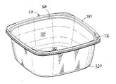
図面において、同じ構成要素には同一符号が使用される。本発明の第1の実施例が図1及び2に示されている。容器10は容器ベース20及びフレキシブルな容器蓋40を含む。図の実施例において、容器10は角が丸い実質的に正方形として記載されている。本発明の他の実施例において、容器100は長方形、円形、楕円形のような他の形状を有してもよい。
In the drawings, the same reference numerals are used for the same components. A first embodiment of the present invention is shown in FIGS. The
容器ベース20は底22及び該底22の周辺から伸張する側壁24を有する。側壁24の終端において、外側にかつ実質的に水平方向に伸張するショルダ26が設けられ、それはベースの閉止部28に組み込まれている。閉止部28は概して水平のリム面30及び略逆U字形状の断面を有する。底面22は実質的に水平の中央パネル面(図示せず)に対して上側に伸張する積み重ね用リセス(図示せず)を備える。
The
容器蓋40は容器ベース20をシール係合するように適応される。本発明のひとつの実施例に従い、容器蓋40は、周辺閉止部またはシールリップ44により包囲された中央パネル42を含む。中央パネル42は、付加的にひとつまたはそれ以上の積み重ね用ビード43を含み、それはベース20の底面22に設けられた積み重ね用リセスと係合する。蓋閉止部44は付加的なグリップタブ48を備えた4つのコーナー46を含む。蓋40の蓋閉止部44はベース閉止部30とシール係合するように適応される。蓋閉止部44は内側壁58と外側壁60との間に配置される水平リム面50を有し、その内側壁と外側壁は一緒になって蓋チャネルを構成する略逆U字形状の断面を形成している。蓋は少なくとも一つの通気ボタン52を備える通気手段を含む。本発明の好適実施例に従い、通気ボタン52は水平リム面50に沿って、好ましくはコーナー部分に、より好ましくはグリップリブ48を備えるコーナー部に配置される。ひとつのコーナーに通気ボタンを配置することにより、容器10が通気状態にある間、蓋の残りの3つのコーナーはシールされたままであり、それによって最適な通気可能シールを与えることができる。他の実施例において、通気ボタン52はコーナー46の中間に配置されてもよいし、蓋チャネルの内側壁58または外側壁60に沿って配置されてもよい。
図3及び4を参照して、容器ベース20の閉止部28は、内側壁32及び外側壁34を含む。上記のように、容器蓋40の閉止部44は内側壁58及び外側壁60を含む。図示のように、蓋40がベース20に固定されたとき、内側壁32が蓋40の内側壁58と締まりばめするように、内側壁32と58はアンダーカット係合で形成されている。こうして、内側壁32及び58はシール面の第1の組を与える。外側壁34及び60もまたシール面の第2の組を与えるようアンダーカット係合で形成されており、内側及び外側で連続したシール領域を有する容器が与えられる。蓋40の閉止部またはシールリップ44は、容器ベース20の閉止部28の水平リム面30を受容するシールチャネルとして作用する。蓋及びベースの上記閉止部の詳細については、ここに参考文献として組み込む米国特許第6,170,696号に記載されている。好適実施例の閉止部のデザインは内側及び外側の両方のシール面を有するとして説明したが、本発明の通気特徴は他の既知のU字形閉止構成によっても同様に機能する。例えば、蓋及びベース閉止部の内側壁(または外側壁)を蓋及びベース閉止部のそれぞれの外側壁(または内側壁)に係合することで主要なシールコンタクトを制限し、付加的な周囲の連続シールゾーンを形成しない略U字形状閉止部デザインである。例えば、上記した実施例において、外側壁34及び60は両方がアンダーカットで形成される必要はなく、いずれかの外側壁が垂直方向かまたは垂直を超えてアンダーカットと反対に外側に傾斜してもよい。
3 and 4, the
ベース20及び蓋40は熱成形部品として製造される。他に、これらの部材のひとつまたは両方はブロー成形または射出成形を含む他の処理により製造されてもよい。しかし、熱成形以外の処理が使用されれば、構造上の小さい修正が生じうることは当業者の知るところである。
The
上記したように、通気手段は、閉止部44に配置された少なくとも一つのフレキシブルな通気ボタンから成る。特定的に、通気ボタン52は、図3及び4に示すように、水平リム面50上に配置される。通気ボタン52は隆起部64を包囲する縁部62を含む。縁部62は水平リム面50と一体成形される。隆起部64は、縁部62によって形成される平面から突出した丸または半球のめくり返し可能なドームのように形成される。丸い形状の結果、隆起部64は、隆起部64の最外突出部を形成する頂点66と、該頂点66を縁部62に一体的に接続する伝達領域を含む。好適には、隆起部64は縁部62の直径の約二分の一である。実際には、隆起部64のめくり返し可能な性質は、縁部62と隆起部64の間の接続位置の材料を薄くすることにより容易となる。蓋が射出成形で形成される場合の他の実施例において、めくり返し可能な隆起部64の厚さは好適に隣接する蓋の厚さの約50%以下である。ここに参考文献として組み込む米国特許出願第2004−0232036号の段落51には、その点が教示されている。
As described above, the ventilation means includes at least one flexible ventilation button arranged in the closing portion 44. Specifically, the
通気ボタン52は、図3に示す非通気の第1位置と、図4及び5に示す通気可能の第2位置との間を移動するように設計されかつ適応されている。通気ボタン52の第1位置において、通気ボタンのめくり返し可能な隆起部64はボトム閉止部28の水平リム面30から離れる方向へ突出している。この位置で、蓋40がベース20に係合するとき、内側壁32及び58はシール接触状態のままである。通気手段の第2位置において、隆起部64は逆になり、ボトム閉止部28の水平リム面30に対面する。頂点66は水平リム面30と接触し、その結果、内側シール壁58が内側壁32とのシール接触から離れ、外側壁34に関して外側壁60が変位して、矢印A、A’及びB、B’で示すように空気の通気通路が与えられる。上記したように、ベース及び蓋閉止部の外側壁34及び60のそれぞれは、シール面の第2の組を形成する必要はなく、所望により垂直または垂直以上のセグメントとして配置されてもよい。
The
通気ボタン52は、外部(または作用)力Fvがボタン52に印加されるまで、配置後には第1及び第2位置を維持するように適応される。当業者に周知なように、典型的に作用力は、蓋閉止部44上でのボタン位置ばかりでなく、容器閉止部及びボタン52の大きさにも依存する。
The
作用力(Fv)は、約0.25〜15.0ポンドの範囲、好ましくは約0.5〜10.0ボンドの範囲、より好ましくは約1.0〜5.0ポンドの範囲である。当業者に周知のように、上記した作用力はそれらの間を容易に移動しながら所望の通気または非通気位置にボタン52を保持するのに十分なものである。
本発明に従い、通気ボタン52は容器の大きさ及び形状に依存してさまざまな大きさを有する。ボタン52付近の容器サイズが約0.3〜0.6インチである一つの実施例において、通気ボタン52は実質的に円形であり、約0.25〜0.6インチの範囲の直径を有する。他の実施例において、通気ボタン52の直径は約0.35から0.55インチの範囲である。
The acting force (Fv) is in the range of about 0.25 to 15.0 pounds, preferably in the range of about 0.5 to 10.0 bonds, more preferably in the range of about 1.0 to 5.0 pounds. As is well known to those skilled in the art, the aforementioned acting forces are sufficient to hold the
In accordance with the present invention, the
上記したように、通気ボタン52は第1位置から第2位置へ移動し、その距離は第2位置において空気の有効な通路を与えるのに十分なものである。実際の移動距離はリム面50と通気ボタン52の大きさ(例えば、水平面幅)に依存する。
As described above, the
通気動作モードの例は以下の通りである。ユーザは、上記した作用力(矢印Fv)を通気ボタン52に印加しながら蓋40のコーナー46をベース20から持ち上げて、めくり返し可能な隆起ドーム部64を第1の非通気位置から第2の通気可能位置まで移動する。通気ボタン52が第2の通気可能位置に移動したとき、めくり返し可能な隆起ドーム部64の頂点66はベース閉止部28のリム面30に接触し、それによってボタン52に隣接する蓋40は、(i)食品の呼吸を容易にし、及び/または(ii)電子レンジ調理中に空気及び蒸気が容器から通気され、冷却中に圧力降下を補償するべく容器10内に十分な空気を戻すことができるように変位または上昇する。
An example of the ventilation operation mode is as follows. The user lifts the
図6は本発明の他の実施例を示す。容器110は図1から5に示すのと同じ容器ベース120、及び容器蓋140から成る。容器蓋140は、通気ボタン52に加え、第2通気ボタン152及び付加的に第3通気ボタン252を有する点を除き、実質的に図1から5に示す容器蓋40と同一である。第1通気ボタン52と同様に、通気ボタン152及び252が蓋140のコーナー領域146に配置されている。通気ボタン152及び252の動作は図3から5に関連して上記したのと同じである。通気ボタン52、152及び252は所望の量の通気を与えるよう選択的に動作してもよい。
FIG. 6 shows another embodiment of the present invention.
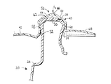
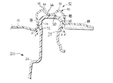
図7から11は本発明の通気可能容器の他の実施例を示す。容器310は容器ベース320及びそれとシール係合するフレキシブルな容器蓋340を含む。容器ベース320は底322及び該底322の周辺から伸張する側壁324を有する。側壁324の終端には、外側かつ実質的に水平方向に伸張するショルダ326が設けられ、それがベースの閉止部328に組み込まれている。閉止部328は概して水平なリム面330を有し、略逆U字形状の断面を有する。
Figures 7 to 11 show another embodiment of the ventable container of the present invention.
容器蓋340は、周辺閉止部またはシールリップ344により包囲された中央パネル342を含む。付加的に中央パネル342はベース320の底面322に設けられた積み重ね用リセス(図示せず)と係合するひとつまたはそれ以上の積み重ね用ビード343を含む。蓋閉止部344は付加的なグリップタブ348を有する4つのコーナー346を含む。蓋340の蓋閉止部334はベース閉止部330とシール係合するよう適応されている。蓋閉止部344は水平なリム面350及び蓋チャネルを形成する略逆U字形状の断面を有する。
図7に示すように、蓋340はさらに通気手段372を含む。
As shown in FIG. 7, the
好適実施例において、通気手段372は、蓋閉止部344に隣接配置される少なくとも一つの突起または通気ボス374から成る。通気ボス374は水平リム面350上に配置されかつ図9及び10に示すように蓋チャネル内に突出している。
In the preferred embodiment, the vent means 372 comprises at least one protrusion or vent
本発明に従い、通気ボス374は蓋閉止部344上の任意の位置に配置可能である。好適には、四角形の場合、通気ボス374は蓋コーナー346に隣接配置される。本発明の好適実施例において、通気ボス374は、コーナー346付近であってグリップタブ348に近接して配置されている。
According to the present invention, the
図8及び9に示すように、容器ボタン320は通気ボス374を受容するよう適応された通気ボスシート336を含み、蓋340及びベース320が係合位置にあるとき、蓋340及び通気ボス374は第1の非通気位置に置かれる。蓋340が回転して第2の通気可能位置に置かれたとき、図10及び11に示すように、通気ボス374が容器の水平リム面330上に配置され、それにより蓋340がボス374付近でわずかに隆起し、空気が通気可能な通路がもたらされる。この第2の通気可能位置において、蓋閉止部344の内壁358は変位し、ベース閉止部328の内壁332とのシール接触が解かれる。また、蓋閉止部344の外側壁360はベース閉止部328の外側壁334に対して変位し、矢印O、O’、及びC、C’で示す空気が通気可能な通路が与えられる。
As shown in FIGS. 8 and 9, the
本発明に従い、通気ボス374は、容器の大きさ及び形状に依存して、さまざまな大きさを取り得る。好適実施例において、通気ボス374は実質的に円形であり、その直径は、好ましくは約0.25〜0.6インチの範囲、より好ましくは約0.35〜0.55インチの範囲である。
In accordance with the present invention, the
容器310を通気可能な位置に置くため、ユーザは蓋340を容器ベース320から取り外し、回転させて、図10及び11に示す通気可能位置の容器ベース320上に蓋340を戻して配置する。正方形の容器の場合、蓋340は90°だけ回転すれば通気可能となる。長方形の容器の場合、蓋340は通気可能位置に移動するのに180°回転する必要がある。上記した通気可能位置において、通気ボス374は蓋340のコーナー346を隆起させ、それにより(i)食品の呼吸を調節でき、及び/または、(ii)電子レンジ調理中に空気及び蒸気が容器から通気可能となり、かつ、冷却中に容器310のシール完全性(リークプルーフ)を実質的に維持しながら圧力低下を補償するべく容器内に十分な空気を戻すことが可能となる。
To place the
完全にシールされた非通気方向に容器310を戻すために、ユーザは蓋340を取り外し、通気ボス374が通気ボスシート336と位置あわせされるように蓋340を回転し、蓋閉止部344がベース閉止部328とシール係合するように蓋をベースに押しつける。
To return the
容器は再利用可能であるが、消費者が使い捨てと考えるほど安価に製造でき、カバーとベースを交換するには別々に店頭で購入すればよい。ベース及びカバーは透明なポリプロピレンホモポリマー材料を熱成形することにより製造される。熱成形により容器を製造するのに適した他のプラスチック材料として、PS(ポリスチレン)、CPET(結晶性ポリエチレンテレフタレート)、APET(アモルファスポリエチレンテレフタレート)、HDPE(高密度ポリエチレン)、PVC(塩化ポリビニル)、PC(ポリカーボネイト)及び発砲ポリプロピレンなどが含まれる。使用される材料は、ユーザが容器の中身を見ることができるように概して透明である。 Although the container is reusable, it can be manufactured as cheaply as the consumer considers it disposable and can be purchased separately at the store to replace the cover and base. The base and cover are manufactured by thermoforming a clear polypropylene homopolymer material. Other plastic materials suitable for producing containers by thermoforming include PS (polystyrene), CPET (crystalline polyethylene terephthalate), APET (amorphous polyethylene terephthalate), HDPE (high density polyethylene), PVC (polyvinyl chloride), Includes PC (polycarbonate) and foamed polypropylene. The material used is generally transparent so that the user can see the contents of the container.
容器は容器カバーと容器ベースとの閉止の視覚的な指標を含んでもよい。視覚的指標はカバーがベースと係合した部分で色が変化するものであってもよい。ひとつの実施例において、カバーの閉止部は第1の色であり、ベースの閉止部は第2の色である。閉止部が係合すると、第1の色と第2の色は第3の色を生成し、ユーザに容器がシールされたことを視覚的に示す。 The container may include a visual indication of closure of the container cover and the container base. The visual indicator may change color at the part where the cover is engaged with the base. In one embodiment, the cover closure is a first color and the base closure is a second color. When the closure is engaged, the first and second colors produce a third color that visually indicates to the user that the container has been sealed.
容器は、ユーザの手が濡れていたり油が付着している場合に、滑りを低減し、つかみやすくするために粗い外側面を有してもよい。 The container may have a rough outer surface to reduce slip and make it easier to grip when the user's hand is wet or oil is attached.
容器は容器内の食品を別々に分けるよう分割されてもよい。仕切りは容器と一体でも別々のコンポーネントでもよい。ベースが仕切りを有してもよいし、ベース及びカバーの両方がそれぞれ仕切りを有してもよい。カバーに配置された仕切りは、はね防止を与えるようベース内の仕切りと部分的に係合してもよいし、コンパートメント間の漏れ防止の度合いを変化させるようベース内の仕切りと完全に係合してもよい。 The container may be divided to separate the food items in the container. The divider may be integral with the container or a separate component. The base may have a partition, and both the base and the cover may each have a partition. A partition located on the cover may partially engage with the partition in the base to provide splash protection, or fully engage with the partition in the base to change the degree of leakage prevention between the compartments. May be.
容器は容器の温度及びその内容物を示す帯片を含んでもよい。 The container may include a strip indicating the temperature of the container and its contents.
グリップタブは、容器の適切なシールを維持する適当な閉止部分をさらに与えながら、カバーの除去または係合中にベースとの干渉接触を減少させる伸長部を有する。グリップタブの伸長部により、容器のその他の周囲のシールを維持しながらカバーの一部がベースから非シール状態となることで通気可能となる。この特徴は、電子レンジ調理の際に有用である。すなわち、容器を通気可能としながらカバーにより食料が電子レンジの内側面に散乱することが防止される。グリップタブを使用することにより、ベースからカバーを取り外すのにより少ない力でよくなる。開ける力を低減させることで、ストレスと疲労による容器破損の可能性を減少させることができる。開ける力の低減により、ユーザは、ベースからカバーを除去しながら容器コンポーネント全体の制御を維持し、かつ、容器内に保存された内容物が散乱する可能性を減少させることができる。 The grip tab has an extension that reduces interference contact with the base during removal or engagement of the cover while still providing a suitable closure to maintain a proper seal of the container. The extending portion of the grip tab allows ventilation by allowing a portion of the cover to be unsealed from the base while maintaining the other seals around the container. This feature is useful when cooking in a microwave oven. That is, the cover prevents the food from being scattered on the inner surface of the microwave oven while allowing the container to vent. By using the grip tab, less force is required to remove the cover from the base. By reducing the opening force, the possibility of container breakage due to stress and fatigue can be reduced. By reducing the opening force, the user can maintain control of the entire container component while removing the cover from the base and reduce the possibility of the contents stored in the container being scattered.
ここで記載した値の範囲は、その範囲内にある個々の値を言及する方法として使用したものに過ぎず、特に示さない限り、個々の値は明細書に組み込まれる。ここに説明したすべての方法は、特に示さない限り、適当な任意の順序で実行可能である。ここに与えられた任意の及びすべての実施例及び例示は本発明をより良く説明するためのものに過ぎず、本発明の態様を制限するものではない。 The ranges of values described herein are merely used as a way of referring to individual values within that range, and unless otherwise indicated, individual values are incorporated into the specification. All methods described herein can be performed in any suitable order unless otherwise indicated. Any and all examples and illustrations given herein are merely for better illustrating the present invention and are not intended to limit the embodiments of the present invention.
発明は特定の実施例との関連で説明されてきたが、本発明はそれらの実施例に限定されない。本発明の思想及び態様から離れることなく、さまざまな修正及び変更が可能であることは当業者の知るところである。また、本発明はここで説明したもの以外の方法で実施することも可能である。したがって、発明の思想及び態様に含まれるすべての変更、修正及び等価をカバーすることが意図されている。さらに、特に断らずまたは文脈に反しない限り、すべての可能な変更における上記構成要素の任意の組み合わせが本発明に含まれるものである。 Although the invention has been described in the context of particular embodiments, the invention is not limited to those embodiments. Those skilled in the art will recognize that various modifications and changes can be made without departing from the spirit and aspects of the invention. The present invention can also be implemented by methods other than those described here. Accordingly, it is intended to cover all changes, modifications, and equivalents included in the spirit and aspects of the invention. Further, any combination of the above-described components in all possible variations is included in the invention unless otherwise indicated or contradicted by context.
Claims (6)
選択的に取り外し可能な蓋であり、前記蓋は中央パネル及び該中央パネルを包囲する周辺シールリップを含み、前記周辺シールリップは蓋チャネルを形成する略逆U字形の断面を有し、前記周辺リールリップは通気ボスを含むところの蓋と、
内部空洞を有する容器ボトムであり、前記容器ボトムは容器リムで終端する側壁を有し、前記容器リムは前記蓋チャネル内に配置されるように適応され、前記容器リムは通気ボスシートを含み、前記容器リムが前記蓋チャネル内に配置され前記蓋及び容器が第1の非通気位置にあるとき、前記ボスシートが前記通気ボスを受容するように適応され、それにより前記蓋と前記容器のシール係合が有効となり、前記蓋が前記容器に関して第2の通気位置に回転されるとき、前記通気ボスは前記通気ボスシートから離れて配置され、前記容器リムが再配置され、前記容器の内部空洞から容器の外部に向かって前記蓋チャネル内に空気が通気可能な通路がもたらされる、ところの容器ボトムと、
を備えることを特徴とする容器。 A breathable container,
A selectively removable lid, wherein the lid includes a central panel and a peripheral seal lip surrounding the central panel, the peripheral seal lip having a generally inverted U-shaped cross section forming a lid channel; The reel lip has a lid that includes a vent boss,
A container bottom having an internal cavity, the container bottom having a side wall terminating in a container rim, the container rim being adapted to be disposed in the lid channel, the container rim comprising a vent boss sheet, When a container rim is disposed in the lid channel and the lid and container are in a first non-vented position, the boss sheet is adapted to receive the vent boss, thereby sealing engagement of the lid and the container Becomes effective and when the lid is rotated to a second vent position with respect to the container, the vent boss is positioned away from the vent boss seat, the container rim is repositioned, and A container bottom where an air-permeable passage is provided in the lid channel towards the outside;
A container comprising:
ことを特徴とする請求項1記載の容器。 When the container rim is disposed in the lid channel and the lid is in the second position, the container remains substantially leak-proof except for the area adjacent to the vent boss;
The container according to claim 1.
Applications Claiming Priority (2)
| Application Number | Priority Date | Filing Date | Title |
|---|---|---|---|
| US69249605P | 2005-06-21 | 2005-06-21 | |
| PCT/US2006/021809 WO2007001748A1 (en) | 2005-06-21 | 2006-06-05 | Venting container |
Publications (2)
| Publication Number | Publication Date |
|---|---|
| JP2008546607A true JP2008546607A (en) | 2008-12-25 |
| JP2008546607A5 JP2008546607A5 (en) | 2009-07-16 |
Family
ID=37595424
Family Applications (1)
| Application Number | Title | Priority Date | Filing Date |
|---|---|---|---|
| JP2008518191A Withdrawn JP2008546607A (en) | 2005-06-21 | 2006-06-05 | Breathable container |
Country Status (11)
| Country | Link |
|---|---|
| US (1) | US20080203096A1 (en) |
| EP (1) | EP1899237A4 (en) |
| JP (1) | JP2008546607A (en) |
| KR (1) | KR20080036556A (en) |
| CN (1) | CN101282885B (en) |
| AU (1) | AU2006262686A1 (en) |
| CA (1) | CA2611747A1 (en) |
| HK (1) | HK1124296A1 (en) |
| NZ (1) | NZ564244A (en) |
| WO (1) | WO2007001748A1 (en) |
| ZA (1) | ZA200710753B (en) |
Cited By (1)
| Publication number | Priority date | Publication date | Assignee | Title |
|---|---|---|---|---|
| KR20150138636A (en) * | 2014-06-02 | 2015-12-10 | 한국식품연구원 | Method for prolonging freshness of mulberry and packing case for prolonging freshness |
Families Citing this family (22)
| Publication number | Priority date | Publication date | Assignee | Title |
|---|---|---|---|---|
| US7866502B2 (en) * | 2005-06-21 | 2011-01-11 | The Glad Products Company | Venting container |
| WO2007084892A2 (en) * | 2006-01-18 | 2007-07-26 | The Glad Products Company | Containers with interlocking covers |
| US20110089187A1 (en) * | 2006-08-10 | 2011-04-21 | Capitol Vial Inc. | Shatterproof Container And Cap Assembly |
| US8083094B2 (en) * | 2006-08-10 | 2011-12-27 | Capitol Vial Inc. | Container and cap assembly |
| US20110210033A1 (en) * | 2008-09-18 | 2011-09-01 | Khim Seang Chhay | Stackable container with interlocking arrangement |
| US8875927B2 (en) | 2009-09-23 | 2014-11-04 | Anchor Packaging, Inc. | Container with self-venting features |
| US8430268B2 (en) * | 2010-05-27 | 2013-04-30 | David Weiss | Lid having a circumferential rim with a plurality of annular ribs |
| US9340330B2 (en) | 2010-06-24 | 2016-05-17 | S. C. Johnson & Son, Inc. | Storage container lids |
| DE102011000392B4 (en) * | 2011-01-28 | 2014-02-06 | Emsa Gmbh | Aufbewahrungsbehälterset |
| NZ591286A (en) | 2011-02-22 | 2014-03-28 | Sist Plastics Ltd | Lidded containers and components |
| CN103086060A (en) * | 2013-01-07 | 2013-05-08 | 四川大学 | Container cover preventing soup bases from shaking overflowing |
| USD741171S1 (en) | 2013-07-19 | 2015-10-20 | S.C. Johnson & Son, Inc. | Container |
| USD744294S1 (en) * | 2013-10-01 | 2015-12-01 | Jacqueline Linder | Container |
| USD744295S1 (en) * | 2013-10-01 | 2015-12-01 | Jacqueline Linder | Container |
| USD776495S1 (en) * | 2014-04-08 | 2017-01-17 | Genius Gmbh | Food slicer |
| USD759478S1 (en) * | 2014-06-04 | 2016-06-21 | Peninsula Packaging, Llc | Container |
| US20160045076A1 (en) * | 2014-08-13 | 2016-02-18 | Dart Industries Inc. | Bread storage container |
| US20190106247A1 (en) * | 2015-04-20 | 2019-04-11 | 9065-3395 Quebec Inc. | Container and lid assembly |
| GB2544273A (en) * | 2015-11-06 | 2017-05-17 | Innovation Assets Ltd | A cover for a cooking vessel |
| EP3994068A1 (en) * | 2019-08-19 | 2022-05-11 | Zume, Inc. | Leak-resistant tray and lid |
| TWI700226B (en) * | 2019-11-08 | 2020-08-01 | 南部化成股份有限公司 | Unequal length identification open container |
| USD1021555S1 (en) * | 2022-01-13 | 2024-04-09 | Cambro Manufacturing Company | Flanged sealed lid |
Family Cites Families (12)
| Publication number | Priority date | Publication date | Assignee | Title |
|---|---|---|---|---|
| US2272018A (en) * | 1939-06-30 | 1942-02-03 | Standard Lime And Stone Compan | Hot top and element for producing the same |
| US4910032A (en) * | 1988-11-16 | 1990-03-20 | Hercules Incorporated | Water-permeable controlled atmosphere packaging device from cellophane and microporous film |
| US5046331A (en) * | 1989-07-25 | 1991-09-10 | Russell A Division Of Ardco, Inc. | Evaporative condenser |
| US5165947A (en) * | 1990-03-26 | 1992-11-24 | Dowbrands, Inc. | Controlled atmosphere, controlled humidity package for red-ripe tomatoes |
| US5354569A (en) * | 1992-07-16 | 1994-10-11 | Brown Richard S | Method of packaging lettuce for storing and shipping |
| US5759650A (en) * | 1994-12-22 | 1998-06-02 | Plicon | Bloomin lid controlled atmosphere package |
| US6170696B1 (en) * | 1996-03-04 | 2001-01-09 | The Glad Products Company | Sealing container |
| US5916615A (en) * | 1997-06-18 | 1999-06-29 | W. R. Grace & Co.-Conn. | Case-ready packages having smooth, gas-permeable substrates on the bottoms thereof to reduce or prevent discoloration when placed in a stack |
| US6013293A (en) * | 1997-09-10 | 2000-01-11 | Landec Corporation | Packing respiring biological materials with atmosphere control member |
| US6105810A (en) * | 1998-11-06 | 2000-08-22 | Dart Industries Inc. | Cookware lid and handle assemblies |
| US6868980B2 (en) * | 2003-06-16 | 2005-03-22 | S. C. Johnson Home Storage, Inc. | Container with detachable, selectively vented lid |
| US20050082305A1 (en) * | 2003-10-15 | 2005-04-21 | Dais Brian C. | Container with selectively vented lid |
-
2006
- 2006-06-05 KR KR1020077029691A patent/KR20080036556A/en not_active Application Discontinuation
- 2006-06-05 AU AU2006262686A patent/AU2006262686A1/en not_active Abandoned
- 2006-06-05 CN CN2006800223319A patent/CN101282885B/en not_active Expired - Fee Related
- 2006-06-05 US US11/916,524 patent/US20080203096A1/en not_active Abandoned
- 2006-06-05 JP JP2008518191A patent/JP2008546607A/en not_active Withdrawn
- 2006-06-05 NZ NZ564244A patent/NZ564244A/en not_active IP Right Cessation
- 2006-06-05 WO PCT/US2006/021809 patent/WO2007001748A1/en active Application Filing
- 2006-06-05 EP EP06772209A patent/EP1899237A4/en not_active Withdrawn
- 2006-06-05 CA CA002611747A patent/CA2611747A1/en not_active Abandoned
-
2007
- 2007-12-11 ZA ZA200710753A patent/ZA200710753B/en unknown
-
2009
- 2009-03-03 HK HK09102021.0A patent/HK1124296A1/en not_active IP Right Cessation
Cited By (2)
| Publication number | Priority date | Publication date | Assignee | Title |
|---|---|---|---|---|
| KR20150138636A (en) * | 2014-06-02 | 2015-12-10 | 한국식품연구원 | Method for prolonging freshness of mulberry and packing case for prolonging freshness |
| KR101580634B1 (en) * | 2014-06-02 | 2015-12-28 | 한국식품연구원 | Method for prolonging freshness of mulberry and packing case for prolonging freshness |
Also Published As
| Publication number | Publication date |
|---|---|
| KR20080036556A (en) | 2008-04-28 |
| EP1899237A4 (en) | 2010-09-01 |
| WO2007001748A1 (en) | 2007-01-04 |
| NZ564244A (en) | 2009-11-27 |
| CN101282885A (en) | 2008-10-08 |
| US20080203096A1 (en) | 2008-08-28 |
| ZA200710753B (en) | 2008-10-29 |
| AU2006262686A1 (en) | 2007-01-04 |
| CN101282885B (en) | 2010-10-06 |
| EP1899237A1 (en) | 2008-03-19 |
| HK1124296A1 (en) | 2009-07-10 |
| CA2611747A1 (en) | 2007-01-04 |
Similar Documents
| Publication | Publication Date | Title |
|---|---|---|
| JP2008546473A (en) | Breathable container | |
| JP2008546607A (en) | Breathable container | |
| JP4691554B2 (en) | Ventable container assembly | |
| US8322553B2 (en) | Self-venting container having a lid that remains attached to a base during venting | |
| JP2008546473A5 (en) | ||
| GB2538397A (en) | Ventable storage container and method of use | |
| EP1892197B1 (en) | Fast freeze container and seal | |
| CN202924058U (en) | Container | |
| KR20070005720A (en) | Ventable spin lock container | |
| JP2008546607A5 (en) | ||
| US11117720B2 (en) | Closure vent for tamper evident container | |
| JP2010215259A (en) | Food packaging container for microwave oven cooking | |
| JP2009029441A (en) | Packaging container |
Legal Events
| Date | Code | Title | Description |
|---|---|---|---|
| A521 | Request for written amendment filed |
Free format text: JAPANESE INTERMEDIATE CODE: A523 Effective date: 20090601 |
|
| A621 | Written request for application examination |
Free format text: JAPANESE INTERMEDIATE CODE: A621 Effective date: 20090601 |
|
| RD01 | Notification of change of attorney |
Free format text: JAPANESE INTERMEDIATE CODE: A7426 Effective date: 20080131 |
|
| RD01 | Notification of change of attorney |
Free format text: JAPANESE INTERMEDIATE CODE: A7426 Effective date: 20080131 |
|
| A761 | Written withdrawal of application |
Free format text: JAPANESE INTERMEDIATE CODE: A761 Effective date: 20111028 |
|
| A977 | Report on retrieval |
Free format text: JAPANESE INTERMEDIATE CODE: A971007 Effective date: 20111102 |