JP2008544864A - Portable power tools - Google Patents
Portable power tools Download PDFInfo
- Publication number
- JP2008544864A JP2008544864A JP2008518565A JP2008518565A JP2008544864A JP 2008544864 A JP2008544864 A JP 2008544864A JP 2008518565 A JP2008518565 A JP 2008518565A JP 2008518565 A JP2008518565 A JP 2008518565A JP 2008544864 A JP2008544864 A JP 2008544864A
- Authority
- JP
- Japan
- Prior art keywords
- portable power
- piston
- air
- power tool
- fuel
- Prior art date
- Legal status (The legal status is an assumption and is not a legal conclusion. Google has not performed a legal analysis and makes no representation as to the accuracy of the status listed.)
- Pending
Links
Images

Classifications
-
- B—PERFORMING OPERATIONS; TRANSPORTING
- B25—HAND TOOLS; PORTABLE POWER-DRIVEN TOOLS; MANIPULATORS
- B25C—HAND-HELD NAILING OR STAPLING TOOLS; MANUALLY OPERATED PORTABLE STAPLING TOOLS
- B25C1/00—Hand-held nailing tools; Nail feeding devices
- B25C1/08—Hand-held nailing tools; Nail feeding devices operated by combustion pressure
Abstract
ガス燃焼機構により動力が供給される携帯動力工具を開示する。同ガス燃焼機構は、第1のピストン(4)及び空気取入れバルブ(6)を有する第1の点火筒(2)を備える。点火筒(2)は第2のピストン(14)を備える第2の搬送筒(12)と連通する燃焼室(10)と移送バルブ(8)を介して連通する。使用時に、第1のピストン(4)は空気を圧縮して、移送バルブ(8)を介して圧縮された空気を燃焼室(10)に移送するように設けられる。燃焼室(10)は点火筒(2)から圧縮された空気を受承し、燃料供給口(16)から燃料ガスを受承するように設けられる。同室内において空気及び燃料ガスは混合されて、空気及びガスの混合体を形成する。燃焼室(10)は、同燃焼室内において空気及び燃料の混合体を点火し、第2のピストン(14)を駆動して容易に工具を操作できるようにも設けられる。 A portable power tool powered by a gas combustion mechanism is disclosed. The gas combustion mechanism includes a first ignition cylinder (2) having a first piston (4) and an air intake valve (6). The ignition cylinder (2) communicates with the combustion chamber (10) communicating with the second conveyance cylinder (12) including the second piston (14) via the transfer valve (8). In use, the first piston (4) is provided to compress air and transfer the compressed air to the combustion chamber (10) via the transfer valve (8). The combustion chamber (10) is provided to receive compressed air from the ignition cylinder (2) and to receive fuel gas from the fuel supply port (16). In the same room, air and fuel gas are mixed to form a mixture of air and gas. The combustion chamber (10) is also provided so that a tool can be easily operated by igniting a mixture of air and fuel in the combustion chamber and driving the second piston (14).
Description
本発明は、内燃式の携帯動力工具に関する。本発明は、特に、釘打ちガンの形態における内燃式の留め具打込工具に関する。 The present invention relates to an internal combustion type portable power tool. The invention relates in particular to an internal combustion type fastener driving tool in the form of a nailing gun.
内部における燃焼を動力源として使用する携帯動力工具が周知である。特に、例えば釘のような留め具を作業片や基板内に打ち込む留め具打込工具が周知である。工具は、燃焼室内において燃料及び空気の混合体を点火し、強制的にピストンを駆動して工具から留め具を射出する。従来技術による工具の効果は、燃料及び空気の混合体の完全な量の早期の点火の能率により大きく制限される。点火される燃料の量が不十分である場合には、装置は、留め具に好適な動力を伝えることができない。工具の出力する動力が信頼できるものではない場合には、留め具は、打ち込みの深さが不十分なものとなるか、固定が不十分なものとなる。過去における従来技術による装置においては、工具を大型化したり、燃料の量を増加して浪費したりしてこれらの課題を解決しようとしてきた。 Portable power tools that use internal combustion as a power source are well known. In particular, a fastener driving tool for driving a fastener such as a nail into a work piece or a substrate is well known. The tool ignites the fuel and air mixture in the combustion chamber and forces the piston to eject the fasteners from the tool. The effectiveness of prior art tools is greatly limited by the efficiency of early ignition of the full amount of fuel and air mixture. If the amount of fuel that is ignited is insufficient, the device cannot transmit suitable power to the fastener. If the power output by the tool is not reliable, the fastener will have an insufficient depth of driving or insufficiently fixed. In the devices according to the prior art in the past, it has been attempted to solve these problems by increasing the size of the tool or increasing the amount of fuel to be wasted.
このような従来技術の装置の例は、特許文献1に開示され、その全体がここで開示されたものとする。
本発明は、工具を大型化したり、燃料の量を増加して浪費したりすることなく、好適な動力を出力することができる携帯動力工具を提供することを目的とする。 An object of the present invention is to provide a portable power tool that can output suitable power without increasing the size of the tool or increasing the amount of fuel.
従来技術の短所に対して、本発明は、携帯動力工具、及び留め具打込工具を提供するものとする。これにより、従来技術の短所の少なくとも1つを緩和又は解決する。或いは、有効な代替物を提供する。 In contrast to the disadvantages of the prior art, the present invention shall provide a portable power tool and a fastener driving tool. This mitigates or resolves at least one of the disadvantages of the prior art. Alternatively, provide an effective alternative.
本発明の側面において、ガス燃焼機構により動力が供給される携帯動力工具を開示する。同ガス燃焼機構は、第1のピストン及び空気取入れバルブを有する第1の点火筒を備える。点火筒は第2のピストンを備える第2の搬送筒と連通する燃焼室と移送バルブを介して連通する。使用時に、第1のピストンは空気を圧縮して、移送バルブを介して圧縮された空気を燃焼室に移送するように設けられる。燃焼室は点火筒から圧縮された空気を受承し、燃料供給口から燃料ガスを受承して、同室内において空気及び燃料ガスは混合されて、空気及びガスの混合体を形成するように設けられる。燃焼室及び第2の搬送筒は、燃焼室内において空気及び燃料の混合体を点火し、第2のピストンを駆動して容易に工具を操作できるように設けられる。 In an aspect of the invention, a portable power tool is disclosed that is powered by a gas combustion mechanism. The gas combustion mechanism includes a first ignition cylinder having a first piston and an air intake valve. The ignition cylinder communicates with a combustion chamber communicating with a second conveyance cylinder having a second piston via a transfer valve. In use, the first piston is provided to compress air and transfer the compressed air to the combustion chamber via a transfer valve. The combustion chamber receives compressed air from the ignition cylinder, receives fuel gas from the fuel supply port, and the air and fuel gas are mixed in the chamber to form a mixture of air and gas. Provided. The combustion chamber and the second transfer cylinder are provided so that the tool can be easily operated by igniting a mixture of air and fuel in the combustion chamber and driving the second piston.
好適には、第1のピストンは、圧縮された空気が燃焼室に移送されるに先立って1サイクル以上の間駆動される。
好適には、圧縮された空気及び燃料のそれぞれが、第2のピストンに付与される動作の特定の動力又は時間の性質に最適化される規定の時間に圧縮された燃焼室内に案内される。
Preferably, the first piston is driven for one or more cycles prior to the compressed air being transferred to the combustion chamber.
Preferably, each of the compressed air and fuel is guided into a compressed combustion chamber at a defined time that is optimized for the particular power or time nature of the motion imparted to the second piston.
好適には、燃料及び圧縮された空気は、燃焼室に同時に供給される。
好適には、燃料供給口は、燃料噴射口から構成され、同噴射口は、動力工具の作動サイクルを少なくとも一度駆動するように設けられる。
Preferably, fuel and compressed air are supplied to the combustion chamber simultaneously.
Preferably, the fuel supply port is constituted by a fuel injection port, and the injection port is provided so as to drive the operating cycle of the power tool at least once.
好適には、燃料噴射口は、空気及び燃料の混合を促進するように噴射した燃料が容易に霧化するような形状に形成されている。
好適には、第1のピストンは、燃焼室内が少なくとも0.3バール(約30kPa)になるような圧力を付与する程度まで空気を圧縮するように設けられる。
Preferably, the fuel injection port is formed in such a shape that the injected fuel is easily atomized so as to promote mixing of air and fuel.
Preferably, the first piston is provided to compress the air to such an extent that it provides a pressure such that the combustion chamber is at least 0.3 bar (about 30 kPa).
好適には、第1のピストンは、機械的に、或いは電磁的に駆動される。
好適には、燃料供給口は、電磁的な、或いは機械的な駆動により開閉するバルブを備える。
Preferably, the first piston is driven mechanically or electromagnetically.
Preferably, the fuel supply port includes a valve that opens and closes by electromagnetic or mechanical drive.
好適には、第1のピストンは、加圧された空気を収容する内部受領器を有する。
好適には、半可撓性の口部を有する封止リングが第2のピストンの周囲に設けられる。好適には、混合ファンが燃焼室の内部に回転自在に取り付けられる。
Preferably, the first piston has an internal receiver that contains pressurized air.
Preferably, a sealing ring having a semi-flexible mouth is provided around the second piston. Preferably, the mixing fan is rotatably mounted inside the combustion chamber.
好適には、外付けのモータが電磁結合を介して混合ファンを駆動する。
好適には、燃焼室は、同燃焼室と排気プレナムとを連通させる板弁が開くと排気される。
Preferably, an external motor drives the mixing fan via electromagnetic coupling.
Preferably, the combustion chamber is evacuated when a plate valve that communicates the combustion chamber and the exhaust plenum is opened.
好適には、第1の位置及び第2の位置の間を移動自在な機構は、第2の位置と係合するラッチ手段を備える。機構が第1の位置からラッチ手段が係合した第2の位置に移動すると、空気及び燃料ガス混合体が第2のピストンにより更に圧縮される。空気及び燃料の混合体の点火による動力は、ラッチ手段を乗り越え第2のピストンを駆動する。 Preferably, the mechanism movable between the first position and the second position comprises latch means for engaging the second position. As the mechanism moves from the first position to the second position with the latch means engaged, the air and fuel gas mixture is further compressed by the second piston. The power from the ignition of the mixture of air and fuel overcomes the latch means and drives the second piston.
好適には、緩衝器が第2の搬送筒の底部近傍に設けられ。緩衝器は移動の際の底部において第2のピストンにより圧縮されるように配置される。続いて緩衝器は復元され、第2のピストンを強制的に第2の搬送筒上に戻すように更に配置される。 Preferably, a shock absorber is provided near the bottom of the second transport cylinder. The shock absorber is arranged to be compressed by the second piston at the bottom during movement. The shock absorber is then restored and further arranged to force the second piston back onto the second transport cylinder.
好適には、緩衝器の内部は、緩衝器が圧縮される場合に、排出バルブを介して移送路を通過させて圧縮された空気を第1の点火筒に移送するように設けられた室を形成する。
好適には、燃焼室は、第2の搬送筒から空間的に分離されている。
Preferably, the interior of the shock absorber has a chamber provided to transport the compressed air through the transfer path through the discharge valve to the first ignition cylinder when the shock absorber is compressed. Form.
Preferably, the combustion chamber is spatially separated from the second transport cylinder.
好適には、工具は、1つ以上の空気及び燃料のうち少なくともいずれか一方の取入れバルブを備える。
工具は留め具打込手段を備える。同手段は、留め具が通過して発射されるノーズと、留め具を同ノーズに案内する装填手段とを備える。第2のピストンの作動により、ノーズから留め具が推進されるように配置される。
Preferably, the tool comprises an intake valve for at least one of one or more air and fuel.
The tool comprises fastener driving means. The means comprises a nose fired through the fastener and loading means for guiding the fastener to the nose. The fastener is propelled from the nose by actuation of the second piston.
好適には、留め具打込手段は、釘止めガンである。 Preferably, the fastener driving means is a nail gun.
本出願は、国際公開第2005/063449号パンフレットに関し、その全体がここで開示されたものとする。
本発明は、釘止めガンの形態における動力の駆動による携帯工具を提供する。釘を推進させることに要する動力の少なくとも一部は、ガス燃焼機構により提供される。
This application is related to WO 2005/063449, the entirety of which is disclosed herein.
The present invention provides a portable tool with power drive in the form of a nail gun. At least a portion of the power required to propel the nail is provided by the gas combustion mechanism.
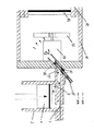
工具の操作の詳細な説明のほとんどは、国際公開第2005/063449号パンフレットにおいて、既に開示されている。図1及び2にも示すように、本発明のガス燃焼機構は、第1のピストン4及び空気取入れバルブ6を有する第1の点火筒2を備える。点火筒2は、第2のピストン14を有する第2の搬送筒12に連結される燃焼室10と移送バルブ8を介して連通する。本実施例において、燃焼室は搬送筒から空間的に分離されているものの、同燃焼室は筒の一部を占有もするものといえる。
Most of the detailed description of the operation of the tool has already been disclosed in WO 2005/063449. As shown also in FIGS. 1 and 2, the gas combustion mechanism of the present invention includes a
移送バルブ8からの加圧された空気は、空気注入口15を介して燃焼室10に進入する。燃焼室10は、燃料供給口16を介して燃料を供給されもする。供給口は、例えば、燃料供給バルブのような、様々な形態及び形状を取り得る。しかしながら、図1に示す実施例においては、口は燃料噴射口18を備える。シール20により容易に燃料噴射口18を組み立てることができる。
Pressurized air from the
図1に示す本発明の第1の実施例において、燃料噴射口16は、空気注入口15に隣接して配置される。従って、燃料及び空気は、極めて近接して燃焼室に進入する。しかしながら、図2に示す第2の実施例において、燃料は、充填する空気が供給される位置とは別の位置に射出される。燃料及び空気は、特定の設計及び必要な性能により別の角度で案内されてもよい。空気及び燃料のうち少なくともいずれか一方を案内する1つ以上の注入口を設けてもよい。
In the first embodiment of the present invention shown in FIG. 1, the
燃焼室10は、移送バルブからの圧縮された空気を受承するように設けられ、これにより、燃料噴射口から得られる燃料ガスと容易に混合できる。混合は、加圧された空気及び燃料が共通の入口に進入することにより単純に発生する。モータ組立体24により駆動されるファン22は、混合を促進するために使用されてもよい。更に、燃料噴射口18は、空気及び燃料の混合を促進するように、噴射された燃料の霧化を促すような形状に形成されてもよい。
The
図1及び2のそれぞれに示す実施例の、より詳細な説明において、第1のピストン4は、クランク及びモータ(図示しない)によって操作され、筒2内において、往復運動する。ピストン4が下方に移動すると、空気は、空気取入れバルブ6を介して案内される。ピストン4が上方に移動すると、取入れバルブ6が閉じて移送バルブ8が開き、これにより、加圧された空気が空気注入口15に供給される。高圧において、第1のピストン4は、加圧された空気が燃焼室10内に移送されるに先立って、1サイクル以上に駆動されてもよいものといえる。エネルギーの出力を高めるには、燃焼室10は、例えば、0.3バール(約30kPa)以上の圧力になるように充填されなければならない。
In the more detailed description of the embodiment shown in each of FIGS. 1 and 2, the
充填する空気が空気注入口15を通過すると、燃料が燃料噴射口18を介して空気流路内に噴射される。また、燃焼室の空気及び燃料の混合体による充填作業の間にわたって間隔を置いて1回以上の燃料の適用が可能である。 When the air to be filled passes through the air injection port 15, the fuel is injected into the air flow path through the fuel injection port 18. It is also possible to apply the fuel one or more times at intervals during the filling operation with the combustion chamber air and fuel mixture.
好適な実施例において、空気及び燃料は、同時に燃料室内に案内されるが、燃焼における補充による充填の周期において、順番に、或いは段階的に噴射されてもよい。更に、燃焼段階において、或いは、燃焼室内における燃料の燃焼の80%乃至90%が完了した時点において、追加の燃料、或いは燃料及び充填する空気を燃焼室内に噴射して、エネルギー出力を高めるか、エネルギー出力時間を延ばしてもよい。 In the preferred embodiment, air and fuel are guided into the fuel chamber at the same time, but may be injected in sequence or stepwise in a refilling cycle in combustion. In addition, during the combustion phase or when 80% to 90% of the combustion of the fuel in the combustion chamber is complete, additional fuel, or fuel and filling air, is injected into the combustion chamber to increase energy output, The energy output time may be extended.
上述した燃焼機構は、特定の動力工具において好適に使用される。発明の好適な実施例において、燃焼室10は、空気及び燃料の混合体が内部において点火されて、第2のピストンを駆動して、釘の形態における留め具を推進するように設けられる。本発明を具体化した釘止めガンの操作の詳細な説明は、国際公開第2005/063449号パンフレットにおいて開示される。
The combustion mechanism described above is preferably used in a specific power tool. In the preferred embodiment of the invention, the
釘止めガンを参照して本発明の実施例を上述したが、本発明は、物体が推進されるいかなる適用においても使用可能であるが、これらに限定されるものではない。釘止めの推進工具に直接関係するわけではないが、この燃焼技術に関係するものも構想可能である。このような適用には、例えば、コンクリート用のドリル等が含まれる。 While embodiments of the present invention have been described above with reference to a nail gun, the present invention can be used in any application where an object is propelled, but is not limited thereto. Although not directly related to nailing propulsion tools, those related to this combustion technology can also be envisaged. Such applications include, for example, concrete drills and the like.
ここで使用される用語「構成、備える」(及びその文法的な別の用法)は、「有する」や「含む」のような包含的な意味であり、「〜によってのみ構成される」という限定的な意味で使用されるものではない。 As used herein, the term “comprising, comprising” (and other grammatical uses thereof) has an inclusive meaning such as “having” or “including” and is limited to “consisting only of” It is not used in a technical sense.
Claims (21)
Applications Claiming Priority (2)
| Application Number | Priority Date | Filing Date | Title |
|---|---|---|---|
| AU2005903436A AU2005903436A0 (en) | 2005-06-29 | A hand-held power tool | |
| PCT/AU2006/000920 WO2007000031A1 (en) | 2005-06-29 | 2006-06-29 | A hand-held power tool |
Publications (2)
| Publication Number | Publication Date |
|---|---|
| JP2008544864A true JP2008544864A (en) | 2008-12-11 |
| JP2008544864A5 JP2008544864A5 (en) | 2009-08-13 |
Family
ID=37595019
Family Applications (1)
| Application Number | Title | Priority Date | Filing Date |
|---|---|---|---|
| JP2008518565A Pending JP2008544864A (en) | 2005-06-29 | 2006-06-29 | Portable power tools |
Country Status (7)
| Country | Link |
|---|---|
| US (1) | US7594599B2 (en) |
| EP (1) | EP1899114A4 (en) |
| JP (1) | JP2008544864A (en) |
| CN (1) | CN101218069B (en) |
| CA (1) | CA2613894A1 (en) |
| TW (1) | TW200711799A (en) |
| WO (1) | WO2007000031A1 (en) |
Families Citing this family (9)
| Publication number | Priority date | Publication date | Assignee | Title |
|---|---|---|---|---|
| US8875969B2 (en) * | 2007-02-09 | 2014-11-04 | Tricord Solutions, Inc. | Fastener driving apparatus |
| JP2008255813A (en) * | 2007-04-02 | 2008-10-23 | Max Co Ltd | Gas internal combustion type nail driver |
| JP5067110B2 (en) * | 2007-10-17 | 2012-11-07 | マックス株式会社 | Gas fired driving tool |
| DE102008000167A1 (en) * | 2008-01-29 | 2009-07-30 | Hilti Aktiengesellschaft | Internal combustion setting device |
| JP5365971B2 (en) * | 2008-01-31 | 2013-12-11 | 日立工機株式会社 | Combustion type driving tool |
| CN104144770A (en) * | 2011-10-13 | 2014-11-12 | 多系统私人有限公司 | Hand held power tool for driving fasteners |
| FR2988634B1 (en) * | 2012-04-03 | 2014-03-21 | Illinois Tool Works | REMOVABLE ADAPTER FOR ADMISSION AND MIXING OF AIR AND FUEL FOR A COMBUSTION TOOL |
| US11819989B2 (en) | 2020-07-07 | 2023-11-21 | Techtronic Cordless Gp | Powered fastener driver |
| CA3167425A1 (en) | 2021-07-16 | 2023-01-16 | Techtronic Cordless Gp | Powered fastener driver |
Citations (2)
| Publication number | Priority date | Publication date | Assignee | Title |
|---|---|---|---|---|
| JPS6328574A (en) * | 1986-07-02 | 1988-02-06 | センコ、プロダクツ、インコ | Simple built-in internal combustion type fastener driving tool |
| US20040134961A1 (en) * | 2002-12-23 | 2004-07-15 | Iwan Wolf | Combustion-engined setting tool |
Family Cites Families (30)
| Publication number | Priority date | Publication date | Assignee | Title |
|---|---|---|---|---|
| US3042008A (en) * | 1958-10-18 | 1962-07-03 | Liesse Maurice | Striking machine, chiefly nailing, clamping and the like percussion machines |
| US3850359A (en) * | 1973-05-11 | 1974-11-26 | Fastener Corp | Fastener driving tool |
| FR2291829A1 (en) | 1974-11-20 | 1976-06-18 | Max Co Ltd | STRIKING TOOL CONTROLS IN PARTICULAR BY THE PRESSURE DUE TO GASEOUS COMBUSTION |
| US3967771A (en) * | 1974-12-16 | 1976-07-06 | Smith James E | Self-contained impact tool |
| US4075850A (en) * | 1975-06-07 | 1978-02-28 | Max Co., Ltd. | Striking tool |
| FR2463267A1 (en) * | 1979-08-08 | 1981-02-20 | Liesse Maurice | THERMAL GENERATOR OF PULSES |
| US4403722A (en) * | 1981-01-22 | 1983-09-13 | Signode Corporation | Combustion gas powered fastener driving tool |
| IN157475B (en) * | 1981-01-22 | 1986-04-05 | Signode Corp | |
| US4483473A (en) * | 1983-05-02 | 1984-11-20 | Signode Corporation | Portable gas-powered fastener driving tool |
| US4665868A (en) * | 1985-02-21 | 1987-05-19 | Joseph Adams Technical Arts Ltd. | Differential piston and valving system for detonation device |
| US4773581A (en) * | 1986-06-13 | 1988-09-27 | Hitachi Koki Company, Ltd. | Combustion gas powered tool |
| US4721240A (en) * | 1986-07-02 | 1988-01-26 | Senco Products, Inc. | Cam-controlled self-contained internal combustion fastener driving tool |
| US4913331A (en) * | 1988-10-21 | 1990-04-03 | Hitachi Koki Company, Ltd. | Internal-combustion piston driving apparatus having a decompression channel |
| DE69005786T2 (en) * | 1989-10-27 | 1994-04-28 | Hitachi Koki Kk | Combustion gas powered driving tool for fasteners. |
| DE4032202C2 (en) * | 1990-10-11 | 1999-10-21 | Hilti Ag | Setting tool for fasteners |
| US5191861A (en) * | 1991-07-12 | 1993-03-09 | Stanley-Bostitch, Inc. | Internal combustion actuated portable tool |
| DE4243618A1 (en) * | 1992-12-22 | 1994-06-23 | Hilti Ag | Portable staple gun driven by internal combustion |
| US6123241A (en) * | 1995-05-23 | 2000-09-26 | Applied Tool Development Corporation | Internal combustion powered tool |
| US5680980A (en) * | 1995-11-27 | 1997-10-28 | Illinois Tool Works Inc. | Fuel injection system for combustion-powered tool |
| US5842623A (en) * | 1997-06-16 | 1998-12-01 | Olin Corporation | Gas primed powder actuated tool |
| US6260519B1 (en) * | 1997-12-31 | 2001-07-17 | Porter-Cable Corporation | Internal combustion fastener driving tool accelerator plate |
| US6019075A (en) * | 1998-08-25 | 2000-02-01 | Walbro Corporation | Air and fuel delivery system for fuel injected engines |
| JP3752878B2 (en) * | 1999-03-18 | 2006-03-08 | 日立工機株式会社 | Driving machine |
| DE19950352C2 (en) * | 1999-10-19 | 2002-03-07 | Hilti Ag | Portable, combustion powered tool and method for driving its piston |
| US6786378B2 (en) * | 2002-01-09 | 2004-09-07 | Illinois Tool Works Inc. | Fastener tool having auxiliary fuel cell metering valve stem seal adaptor |
| JP4135069B2 (en) * | 2002-08-09 | 2008-08-20 | 日立工機株式会社 | Combustion type driving tool |
| JP2004200227A (en) * | 2002-12-16 | 2004-07-15 | Alps Electric Co Ltd | Printed inductor |
| US6755159B1 (en) * | 2003-01-20 | 2004-06-29 | Illinois Tool Works Inc. | Valve mechanisms for elongated combustion chambers |
| DE602004023998D1 (en) * | 2003-06-02 | 2009-12-24 | Makita Corp | Engine tool |
| JP2007516845A (en) * | 2003-12-30 | 2007-06-28 | ポリ・システムズ・プロプライエタリー・リミテッド | Fastener driving tool |
-
2006
- 2006-06-29 JP JP2008518565A patent/JP2008544864A/en active Pending
- 2006-06-29 CA CA002613894A patent/CA2613894A1/en not_active Abandoned
- 2006-06-29 US US11/994,172 patent/US7594599B2/en not_active Expired - Fee Related
- 2006-06-29 TW TW095123503A patent/TW200711799A/en unknown
- 2006-06-29 CN CN2006800240136A patent/CN101218069B/en not_active Expired - Fee Related
- 2006-06-29 EP EP06752647A patent/EP1899114A4/en not_active Withdrawn
- 2006-06-29 WO PCT/AU2006/000920 patent/WO2007000031A1/en active Application Filing
Patent Citations (2)
| Publication number | Priority date | Publication date | Assignee | Title |
|---|---|---|---|---|
| JPS6328574A (en) * | 1986-07-02 | 1988-02-06 | センコ、プロダクツ、インコ | Simple built-in internal combustion type fastener driving tool |
| US20040134961A1 (en) * | 2002-12-23 | 2004-07-15 | Iwan Wolf | Combustion-engined setting tool |
Also Published As
| Publication number | Publication date |
|---|---|
| CN101218069B (en) | 2011-05-25 |
| WO2007000031A1 (en) | 2007-01-04 |
| CN101218069A (en) | 2008-07-09 |
| CA2613894A1 (en) | 2007-01-04 |
| US20080203133A1 (en) | 2008-08-28 |
| TW200711799A (en) | 2007-04-01 |
| EP1899114A1 (en) | 2008-03-19 |
| EP1899114A4 (en) | 2009-11-04 |
| US7594599B2 (en) | 2009-09-29 |
Similar Documents
| Publication | Publication Date | Title |
|---|---|---|
| JP2008544864A (en) | Portable power tools | |
| EP2491233B1 (en) | Gas-powered tool motor | |
| US5909836A (en) | Combustion powered tool with combustion chamber lockout | |
| CN101242932B (en) | Gas combustion type driving tool | |
| US6863045B2 (en) | Combustion apparatus having improved airflow | |
| US6889885B2 (en) | Combustion-powered nail gun | |
| US20080217372A1 (en) | Fastener Driving Tool | |
| JP2014528365A (en) | Hand-held power tool for driving fasteners | |
| JP2008544864A5 (en) | ||
| WO2006123692A1 (en) | Fuel gas type hammering tool | |
| JPS63229274A (en) | Box nailing machine | |
| WO2012046217A1 (en) | A driving gas pre-compression fastening device and the corresponding fastening method | |
| AU2006264223A1 (en) | A hand-held power tool | |
| CN100439042C (en) | Fastener driving tool | |
| AU2004308538A1 (en) | Fastener driving tool | |
| JPS63212478A (en) | Box nailing machine | |
| NZ621620B2 (en) | High efficiency engine for combustion nailer |
Legal Events
| Date | Code | Title | Description |
|---|---|---|---|
| A521 | Request for written amendment filed |
Free format text: JAPANESE INTERMEDIATE CODE: A523 Effective date: 20090625 |
|
| A621 | Written request for application examination |
Free format text: JAPANESE INTERMEDIATE CODE: A621 Effective date: 20090625 |
|
| A131 | Notification of reasons for refusal |
Free format text: JAPANESE INTERMEDIATE CODE: A131 Effective date: 20120104 |
|
| A02 | Decision of refusal |
Free format text: JAPANESE INTERMEDIATE CODE: A02 Effective date: 20120605 |