JP2008543717A - Bulletproof laminated structure - Google Patents
Bulletproof laminated structure Download PDFInfo
- Publication number
- JP2008543717A JP2008543717A JP2008517564A JP2008517564A JP2008543717A JP 2008543717 A JP2008543717 A JP 2008543717A JP 2008517564 A JP2008517564 A JP 2008517564A JP 2008517564 A JP2008517564 A JP 2008517564A JP 2008543717 A JP2008543717 A JP 2008543717A
- Authority
- JP
- Japan
- Prior art keywords
- sheet
- glass sheet
- laminated structure
- edge
- glass
- Prior art date
- Legal status (The legal status is an assumption and is not a legal conclusion. Google has not performed a legal analysis and makes no representation as to the accuracy of the status listed.)
- Granted
Links
- 239000000463 material Substances 0.000 claims abstract description 45
- 239000012790 adhesive layer Substances 0.000 claims abstract description 25
- 239000004417 polycarbonate Substances 0.000 claims abstract description 18
- 229920000515 polycarbonate Polymers 0.000 claims abstract description 18
- 238000007872 degassing Methods 0.000 claims abstract description 10
- 239000002775 capsule Substances 0.000 claims abstract description 6
- 239000011521 glass Substances 0.000 claims description 58
- 230000003014 reinforcing effect Effects 0.000 claims description 20
- 239000008393 encapsulating agent Substances 0.000 claims description 13
- 239000004433 Thermoplastic polyurethane Substances 0.000 claims description 10
- 229920002803 thermoplastic polyurethane Polymers 0.000 claims description 10
- 229910000831 Steel Inorganic materials 0.000 claims description 7
- 239000010959 steel Substances 0.000 claims description 7
- 230000003313 weakening effect Effects 0.000 claims description 6
- 239000004760 aramid Substances 0.000 claims description 4
- 229920003235 aromatic polyamide Polymers 0.000 claims description 4
- 239000002131 composite material Substances 0.000 claims description 4
- 229920001577 copolymer Polymers 0.000 claims description 4
- 239000004744 fabric Substances 0.000 claims description 4
- 239000000835 fiber Substances 0.000 claims description 4
- 229920002037 poly(vinyl butyral) polymer Polymers 0.000 claims description 4
- 229920001169 thermoplastic Polymers 0.000 claims description 4
- 229920002635 polyurethane Polymers 0.000 claims description 3
- 239000004814 polyurethane Substances 0.000 claims description 3
- VGGSQFUCUMXWEO-UHFFFAOYSA-N Ethene Chemical compound C=C VGGSQFUCUMXWEO-UHFFFAOYSA-N 0.000 claims description 2
- 239000005977 Ethylene Substances 0.000 claims description 2
- BZHJMEDXRYGGRV-UHFFFAOYSA-N Vinyl chloride Chemical compound ClC=C BZHJMEDXRYGGRV-UHFFFAOYSA-N 0.000 claims description 2
- 229920001971 elastomer Polymers 0.000 claims description 2
- 239000003822 epoxy resin Substances 0.000 claims description 2
- LNEPOXFFQSENCJ-UHFFFAOYSA-N haloperidol Chemical compound C1CC(O)(C=2C=CC(Cl)=CC=2)CCN1CCCC(=O)C1=CC=C(F)C=C1 LNEPOXFFQSENCJ-UHFFFAOYSA-N 0.000 claims description 2
- 238000003780 insertion Methods 0.000 claims description 2
- 230000037431 insertion Effects 0.000 claims description 2
- 229920001084 poly(chloroprene) Polymers 0.000 claims description 2
- 229920000647 polyepoxide Polymers 0.000 claims description 2
- -1 polyethylene terephthalate Polymers 0.000 claims description 2
- 229920000139 polyethylene terephthalate Polymers 0.000 claims description 2
- 239000005020 polyethylene terephthalate Substances 0.000 claims description 2
- 239000005060 rubber Substances 0.000 claims description 2
- 229920002725 thermoplastic elastomer Polymers 0.000 claims description 2
- 229920001187 thermosetting polymer Polymers 0.000 claims description 2
- 239000004416 thermosoftening plastic Substances 0.000 claims description 2
- 230000001681 protective effect Effects 0.000 abstract 1
- 150000002500 ions Chemical class 0.000 description 5
- 239000010410 layer Substances 0.000 description 5
- XQMVBICWFFHDNN-UHFFFAOYSA-N 5-amino-4-chloro-2-phenylpyridazin-3-one;(2-ethoxy-3,3-dimethyl-2h-1-benzofuran-5-yl) methanesulfonate Chemical compound O=C1C(Cl)=C(N)C=NN1C1=CC=CC=C1.C1=C(OS(C)(=O)=O)C=C2C(C)(C)C(OCC)OC2=C1 XQMVBICWFFHDNN-UHFFFAOYSA-N 0.000 description 3
- 239000000853 adhesive Substances 0.000 description 3
- 230000001070 adhesive effect Effects 0.000 description 3
- 238000010304 firing Methods 0.000 description 3
- 239000002184 metal Substances 0.000 description 3
- 239000005361 soda-lime glass Substances 0.000 description 3
- XLYOFNOQVPJJNP-UHFFFAOYSA-N water Chemical compound O XLYOFNOQVPJJNP-UHFFFAOYSA-N 0.000 description 3
- VYPSYNLAJGMNEJ-UHFFFAOYSA-N Silicium dioxide Chemical compound O=[Si]=O VYPSYNLAJGMNEJ-UHFFFAOYSA-N 0.000 description 2
- 238000005229 chemical vapour deposition Methods 0.000 description 2
- 239000007789 gas Substances 0.000 description 2
- 230000007774 longterm Effects 0.000 description 2
- 238000000034 method Methods 0.000 description 2
- 230000035515 penetration Effects 0.000 description 2
- JAWZFTORYMQYDT-UHFFFAOYSA-N 6-hexoxy-6-oxohexanoic acid Chemical compound CCCCCCOC(=O)CCCCC(O)=O JAWZFTORYMQYDT-UHFFFAOYSA-N 0.000 description 1
- OKTJSMMVPCPJKN-UHFFFAOYSA-N Carbon Chemical compound [C] OKTJSMMVPCPJKN-UHFFFAOYSA-N 0.000 description 1
- XUIMIQQOPSSXEZ-UHFFFAOYSA-N Silicon Chemical compound [Si] XUIMIQQOPSSXEZ-UHFFFAOYSA-N 0.000 description 1
- 229910003481 amorphous carbon Inorganic materials 0.000 description 1
- 239000011324 bead Substances 0.000 description 1
- 229910052799 carbon Inorganic materials 0.000 description 1
- 238000003426 chemical strengthening reaction Methods 0.000 description 1
- 230000006835 compression Effects 0.000 description 1
- 238000007906 compression Methods 0.000 description 1
- 230000003247 decreasing effect Effects 0.000 description 1
- 230000032798 delamination Effects 0.000 description 1
- 238000010494 dissociation reaction Methods 0.000 description 1
- 230000005593 dissociations Effects 0.000 description 1
- 238000005538 encapsulation Methods 0.000 description 1
- 238000001125 extrusion Methods 0.000 description 1
- 230000002349 favourable effect Effects 0.000 description 1
- 229920002457 flexible plastic Polymers 0.000 description 1
- 239000012634 fragment Substances 0.000 description 1
- 238000010438 heat treatment Methods 0.000 description 1
- 230000002452 interceptive effect Effects 0.000 description 1
- 238000001755 magnetron sputter deposition Methods 0.000 description 1
- 238000005121 nitriding Methods 0.000 description 1
- 230000002093 peripheral effect Effects 0.000 description 1
- 239000002985 plastic film Substances 0.000 description 1
- 239000004014 plasticizer Substances 0.000 description 1
- 239000002243 precursor Substances 0.000 description 1
- 230000002265 prevention Effects 0.000 description 1
- 230000005855 radiation Effects 0.000 description 1
- 230000002787 reinforcement Effects 0.000 description 1
- 229920005989 resin Polymers 0.000 description 1
- 239000011347 resin Substances 0.000 description 1
- 238000007789 sealing Methods 0.000 description 1
- 229910052710 silicon Inorganic materials 0.000 description 1
- 239000010703 silicon Substances 0.000 description 1
- 239000000377 silicon dioxide Substances 0.000 description 1
- HUAUNKAZQWMVFY-UHFFFAOYSA-M sodium;oxocalcium;hydroxide Chemical compound [OH-].[Na+].[Ca]=O HUAUNKAZQWMVFY-UHFFFAOYSA-M 0.000 description 1
- 238000003892 spreading Methods 0.000 description 1
- 230000000153 supplemental effect Effects 0.000 description 1
Images
Classifications
-
- B—PERFORMING OPERATIONS; TRANSPORTING
- B32—LAYERED PRODUCTS
- B32B—LAYERED PRODUCTS, i.e. PRODUCTS BUILT-UP OF STRATA OF FLAT OR NON-FLAT, e.g. CELLULAR OR HONEYCOMB, FORM
- B32B17/00—Layered products essentially comprising sheet glass, or glass, slag, or like fibres
- B32B17/06—Layered products essentially comprising sheet glass, or glass, slag, or like fibres comprising glass as the main or only constituent of a layer, next to another layer of a specific material
- B32B17/10—Layered products essentially comprising sheet glass, or glass, slag, or like fibres comprising glass as the main or only constituent of a layer, next to another layer of a specific material of synthetic resin
- B32B17/10005—Layered products essentially comprising sheet glass, or glass, slag, or like fibres comprising glass as the main or only constituent of a layer, next to another layer of a specific material of synthetic resin laminated safety glass or glazing
- B32B17/10009—Layered products essentially comprising sheet glass, or glass, slag, or like fibres comprising glass as the main or only constituent of a layer, next to another layer of a specific material of synthetic resin laminated safety glass or glazing characterized by the number, the constitution or treatment of glass sheets
- B32B17/10036—Layered products essentially comprising sheet glass, or glass, slag, or like fibres comprising glass as the main or only constituent of a layer, next to another layer of a specific material of synthetic resin laminated safety glass or glazing characterized by the number, the constitution or treatment of glass sheets comprising two outer glass sheets
- B32B17/10045—Layered products essentially comprising sheet glass, or glass, slag, or like fibres comprising glass as the main or only constituent of a layer, next to another layer of a specific material of synthetic resin laminated safety glass or glazing characterized by the number, the constitution or treatment of glass sheets comprising two outer glass sheets with at least one intermediate layer consisting of a glass sheet
-
- B—PERFORMING OPERATIONS; TRANSPORTING
- B32—LAYERED PRODUCTS
- B32B—LAYERED PRODUCTS, i.e. PRODUCTS BUILT-UP OF STRATA OF FLAT OR NON-FLAT, e.g. CELLULAR OR HONEYCOMB, FORM
- B32B17/00—Layered products essentially comprising sheet glass, or glass, slag, or like fibres
- B32B17/06—Layered products essentially comprising sheet glass, or glass, slag, or like fibres comprising glass as the main or only constituent of a layer, next to another layer of a specific material
- B32B17/10—Layered products essentially comprising sheet glass, or glass, slag, or like fibres comprising glass as the main or only constituent of a layer, next to another layer of a specific material of synthetic resin
- B32B17/10005—Layered products essentially comprising sheet glass, or glass, slag, or like fibres comprising glass as the main or only constituent of a layer, next to another layer of a specific material of synthetic resin laminated safety glass or glazing
- B32B17/10165—Functional features of the laminated safety glass or glazing
- B32B17/10293—Edge features, e.g. inserts or holes
-
- B—PERFORMING OPERATIONS; TRANSPORTING
- B32—LAYERED PRODUCTS
- B32B—LAYERED PRODUCTS, i.e. PRODUCTS BUILT-UP OF STRATA OF FLAT OR NON-FLAT, e.g. CELLULAR OR HONEYCOMB, FORM
- B32B17/00—Layered products essentially comprising sheet glass, or glass, slag, or like fibres
- B32B17/06—Layered products essentially comprising sheet glass, or glass, slag, or like fibres comprising glass as the main or only constituent of a layer, next to another layer of a specific material
- B32B17/10—Layered products essentially comprising sheet glass, or glass, slag, or like fibres comprising glass as the main or only constituent of a layer, next to another layer of a specific material of synthetic resin
- B32B17/10005—Layered products essentially comprising sheet glass, or glass, slag, or like fibres comprising glass as the main or only constituent of a layer, next to another layer of a specific material of synthetic resin laminated safety glass or glazing
- B32B17/10165—Functional features of the laminated safety glass or glazing
- B32B17/10366—Reinforcements of the laminated safety glass or glazing against impact or intrusion
-
- B—PERFORMING OPERATIONS; TRANSPORTING
- B32—LAYERED PRODUCTS
- B32B—LAYERED PRODUCTS, i.e. PRODUCTS BUILT-UP OF STRATA OF FLAT OR NON-FLAT, e.g. CELLULAR OR HONEYCOMB, FORM
- B32B17/00—Layered products essentially comprising sheet glass, or glass, slag, or like fibres
- B32B17/06—Layered products essentially comprising sheet glass, or glass, slag, or like fibres comprising glass as the main or only constituent of a layer, next to another layer of a specific material
- B32B17/10—Layered products essentially comprising sheet glass, or glass, slag, or like fibres comprising glass as the main or only constituent of a layer, next to another layer of a specific material of synthetic resin
- B32B17/10005—Layered products essentially comprising sheet glass, or glass, slag, or like fibres comprising glass as the main or only constituent of a layer, next to another layer of a specific material of synthetic resin laminated safety glass or glazing
- B32B17/1055—Layered products essentially comprising sheet glass, or glass, slag, or like fibres comprising glass as the main or only constituent of a layer, next to another layer of a specific material of synthetic resin laminated safety glass or glazing characterized by the resin layer, i.e. interlayer
- B32B17/10761—Layered products essentially comprising sheet glass, or glass, slag, or like fibres comprising glass as the main or only constituent of a layer, next to another layer of a specific material of synthetic resin laminated safety glass or glazing characterized by the resin layer, i.e. interlayer containing vinyl acetal
-
- B—PERFORMING OPERATIONS; TRANSPORTING
- B32—LAYERED PRODUCTS
- B32B—LAYERED PRODUCTS, i.e. PRODUCTS BUILT-UP OF STRATA OF FLAT OR NON-FLAT, e.g. CELLULAR OR HONEYCOMB, FORM
- B32B17/00—Layered products essentially comprising sheet glass, or glass, slag, or like fibres
- B32B17/06—Layered products essentially comprising sheet glass, or glass, slag, or like fibres comprising glass as the main or only constituent of a layer, next to another layer of a specific material
- B32B17/10—Layered products essentially comprising sheet glass, or glass, slag, or like fibres comprising glass as the main or only constituent of a layer, next to another layer of a specific material of synthetic resin
- B32B17/10005—Layered products essentially comprising sheet glass, or glass, slag, or like fibres comprising glass as the main or only constituent of a layer, next to another layer of a specific material of synthetic resin laminated safety glass or glazing
- B32B17/1055—Layered products essentially comprising sheet glass, or glass, slag, or like fibres comprising glass as the main or only constituent of a layer, next to another layer of a specific material of synthetic resin laminated safety glass or glazing characterized by the resin layer, i.e. interlayer
- B32B17/1077—Layered products essentially comprising sheet glass, or glass, slag, or like fibres comprising glass as the main or only constituent of a layer, next to another layer of a specific material of synthetic resin laminated safety glass or glazing characterized by the resin layer, i.e. interlayer containing polyurethane
-
- B—PERFORMING OPERATIONS; TRANSPORTING
- B32—LAYERED PRODUCTS
- B32B—LAYERED PRODUCTS, i.e. PRODUCTS BUILT-UP OF STRATA OF FLAT OR NON-FLAT, e.g. CELLULAR OR HONEYCOMB, FORM
- B32B17/00—Layered products essentially comprising sheet glass, or glass, slag, or like fibres
- B32B17/06—Layered products essentially comprising sheet glass, or glass, slag, or like fibres comprising glass as the main or only constituent of a layer, next to another layer of a specific material
- B32B17/10—Layered products essentially comprising sheet glass, or glass, slag, or like fibres comprising glass as the main or only constituent of a layer, next to another layer of a specific material of synthetic resin
- B32B17/10005—Layered products essentially comprising sheet glass, or glass, slag, or like fibres comprising glass as the main or only constituent of a layer, next to another layer of a specific material of synthetic resin laminated safety glass or glazing
- B32B17/10807—Making laminated safety glass or glazing; Apparatus therefor
- B32B17/10816—Making laminated safety glass or glazing; Apparatus therefor by pressing
-
- B—PERFORMING OPERATIONS; TRANSPORTING
- B32—LAYERED PRODUCTS
- B32B—LAYERED PRODUCTS, i.e. PRODUCTS BUILT-UP OF STRATA OF FLAT OR NON-FLAT, e.g. CELLULAR OR HONEYCOMB, FORM
- B32B17/00—Layered products essentially comprising sheet glass, or glass, slag, or like fibres
- B32B17/06—Layered products essentially comprising sheet glass, or glass, slag, or like fibres comprising glass as the main or only constituent of a layer, next to another layer of a specific material
- B32B17/10—Layered products essentially comprising sheet glass, or glass, slag, or like fibres comprising glass as the main or only constituent of a layer, next to another layer of a specific material of synthetic resin
- B32B17/10005—Layered products essentially comprising sheet glass, or glass, slag, or like fibres comprising glass as the main or only constituent of a layer, next to another layer of a specific material of synthetic resin laminated safety glass or glazing
- B32B17/10807—Making laminated safety glass or glazing; Apparatus therefor
- B32B17/10972—Degassing during the lamination
-
- F—MECHANICAL ENGINEERING; LIGHTING; HEATING; WEAPONS; BLASTING
- F41—WEAPONS
- F41H—ARMOUR; ARMOURED TURRETS; ARMOURED OR ARMED VEHICLES; MEANS OF ATTACK OR DEFENCE, e.g. CAMOUFLAGE, IN GENERAL
- F41H5/00—Armour; Armour plates
- F41H5/02—Plate construction
- F41H5/04—Plate construction composed of more than one layer
- F41H5/0407—Transparent bullet-proof laminatesinformative reference: layered products essentially comprising glass in general B32B17/06, e.g. B32B17/10009; manufacture or composition of glass, e.g. joining glass to glass C03; permanent multiple-glazing windows, e.g. with spacing therebetween, E06B3/66
-
- F—MECHANICAL ENGINEERING; LIGHTING; HEATING; WEAPONS; BLASTING
- F41—WEAPONS
- F41H—ARMOUR; ARMOURED TURRETS; ARMOURED OR ARMED VEHICLES; MEANS OF ATTACK OR DEFENCE, e.g. CAMOUFLAGE, IN GENERAL
- F41H5/00—Armour; Armour plates
- F41H5/26—Peepholes; Windows; Loopholes
- F41H5/263—Mounting of transparent armoured panels, e.g. bulletproof windows on vehicles
-
- Y—GENERAL TAGGING OF NEW TECHNOLOGICAL DEVELOPMENTS; GENERAL TAGGING OF CROSS-SECTIONAL TECHNOLOGIES SPANNING OVER SEVERAL SECTIONS OF THE IPC; TECHNICAL SUBJECTS COVERED BY FORMER USPC CROSS-REFERENCE ART COLLECTIONS [XRACs] AND DIGESTS
- Y10—TECHNICAL SUBJECTS COVERED BY FORMER USPC
- Y10T—TECHNICAL SUBJECTS COVERED BY FORMER US CLASSIFICATION
- Y10T428/00—Stock material or miscellaneous articles
- Y10T428/24—Structurally defined web or sheet [e.g., overall dimension, etc.]
- Y10T428/24174—Structurally defined web or sheet [e.g., overall dimension, etc.] including sheet or component perpendicular to plane of web or sheet
- Y10T428/24182—Inward from edge of web or sheet
Landscapes
- Engineering & Computer Science (AREA)
- General Engineering & Computer Science (AREA)
- Laminated Bodies (AREA)
- Aiming, Guidance, Guns With A Light Source, Armor, Camouflage, And Targets (AREA)
- Joining Of Glass To Other Materials (AREA)
Abstract
本発明は、接着層(2、4、10)によって接合された少なくとも3つのグレージングシート(1、3、5)およびポリカーボネートシート(11)と、保護用インサート(20)とを備え、上記インサート(20)と、シート(5)の端面と、シート(11)の縁とによって画定される空間に、飛来物のエネルギーを吸収するための材料(30、31)が設けられている防弾積層構造体に関する。上記材料(30、31)は、上記構造体の組み立て時の脱気のための柔軟な材料(30)およびカプセル材料(31)の形態で具現化される。本発明の構造体を備える建築物または移動車両のための高防弾グレージングも開示される。 The present invention comprises at least three glazing sheets (1, 3, 5) and a polycarbonate sheet (11) joined by an adhesive layer (2, 4, 10), and a protective insert (20). 20), a bulletproof laminated structure in which materials (30, 31) for absorbing the energy of flying objects are provided in a space defined by the end face of the sheet (5) and the edge of the sheet (11) About. The material (30, 31) is embodied in the form of a flexible material (30) and a capsule material (31) for degassing during assembly of the structure. High bullet glazing for a building or moving vehicle comprising the structure of the present invention is also disclosed.
Description
本発明は、防弾性の高い積層構造体に関し、特には強化グレージングとして使用されるような透明な高防弾性積層構造体に関する。 The present invention relates to a laminated structure having high anti-elasticity, and more particularly to a transparent highly anti-elastic laminated structure used as reinforced glazing.
用語「防弾」は、本発明の文脈においては、FR EN 1063規格のレベルBR3(口径:375 Magnum)、BR4(口径:44 Magnum)、BR5(口径:5.56×45)、およびレベルBR6(口径:7.62×51)までの耐性を意味し、特にはKalachnikov弾(口径:7.62×39)への耐性をさらに意味する。 The term “ballistic” is used in the context of the present invention in the FR EN 1063 standard level BR3 (caliber: 375 Magnum), BR4 (caliber: 44 Magnum), BR5 (caliber: 5.56 × 45), and level BR6 ( It means resistance to caliber: 7.62 × 51), and in particular means resistance to Kalachnikov bullets (caliber: 7.62 × 39).
ここでの強化グレージングは、建築用グレージングとしての使用に特に適しており、あるいは装甲移動車両のグレージングに特に適している。 The reinforced glazing here is particularly suitable for use as an architectural glazing or is particularly suitable for glazing of armored mobile vehicles.
本発明の高防弾性の積層構造体は、積層構造体の空洞へと外周の金属製の強化インサートを、積層構造体を構成しているガラスシートのうちの1つの延長に0.2から1.3mmの間隔をあけつつ導入して含む。 In the laminated structure with high anti-ballistic strength of the present invention, the outer peripheral metal reinforcing insert is inserted into the cavity of the laminated structure and 0.2 to 1 is extended to one of the glass sheets constituting the laminated structure. Introduced and included with a spacing of 3 mm.
さらに、多くの移動車両の窓は、その外周が、水平に対して例えば約45°の特定の角度をなしている。したがって、水平方向の銃弾も、この外周において、やはり約45°の入射角度を有する。 Furthermore, the windows of many mobile vehicles have a specific angle, for example about 45 °, with respect to the horizontal. Therefore, the horizontal bullets also have an incident angle of about 45 ° on this circumference.
本発明者らは、このような状況の下、インサートによって境界付けられた領域において、インサートから近い距離(特には、インサートの内縁から15から20mm)に撃ち込まれる銃弾によって、車両の内部に被害が生じがちであることに気が付いた。具体的には、衝撃を吸収するのがガラスの約200mmの領域であり、車両の内側の面を通常は形成しているポリカーボネートが、ガラスの破片を車両の内部へと飛散させがちな様相で変形する。 Under these circumstances, the inventors have caused damage to the interior of the vehicle by a bullet shot at a distance close to the insert (especially 15 to 20 mm from the inner edge of the insert) in the region bounded by the insert. I noticed that it tends to happen. Specifically, it is an area of about 200 mm of glass that absorbs the impact, and the polycarbonate that normally forms the inner surface of the vehicle tends to scatter glass fragments into the interior of the vehicle. Deform.
したがって、本発明の目的は、外周強化インサートの内縁の近くに、特には約45°の入射角にて発射された1つ以上の銃弾から、ユーザを保護することにある。 Accordingly, it is an object of the present invention to protect the user from one or more bullets fired near the inner edge of the perimeter reinforcing insert, particularly at an incident angle of about 45 °.
この目的のため、本発明の主題は、少なくとも、第1のガラスシート、接着層を介して第1のガラスシートへと接続されており、その縁が少なくとも1辺において第1のガラスシートの縁から後退している第2のガラスシート、接着層を介して第2のガラスシートへと接続された第3のガラスシートであって、第2のガラスシートの縁が、少なくとも上記1辺において、第1のガラスシートの縁からそれ自身が後退している第3のガラスシートの縁からさらに後退している第3のガラスシート、場合によっては、1つ以上の接着層を介して第3のガラスシートへと接続され、必要に応じては互いに接続される1つ以上の追加のガラスシート、接着層を介して第3のガラスシートすなわち最後のガラスシートへと接続され、飛来物の衝撃を弱めるためのシート、および高防弾性の材料で製作され、少なくとも上記1辺において、第1および第3のガラスシートの縁ならびに第2のガラスシートの端面によって境界付けられた空洞の少なくとも一部を占めている強化インサートを順に備える積層構造体である。本発明によるこの積層構造体は、少なくとも上記1辺において、第3のガラスシートおよび上記追加のガラスシートの縁が、飛来物の衝撃を弱めるためのシートの縁から後退させられている点、強化インサートと、第3のガラスシートの端面と、飛来物の衝撃を弱めるためのシートの縁との間の空間が、飛来物のエネルギーを吸収することができる材料によって少なくとも部分的に占められている点、飛来物のエネルギーを吸収することができるこの材料が、流動および積層構造体の組み立て時の脱気の保証が可能な材料を介して、強化インサート、第3のガラスシートの端面、および飛来物の衝撃を弱めるためのシートへと接合されている点、ならびに組み立ての際に流動する材料を通さず、積層構造体への水分の進入に対して不透過性であるカプセル材料が、少なくともこの積層構造体の端面のうちの、飛来物の衝撃を弱めるためのシートの端面と強化インサートの少なくとも一部分との間に位置する部分をカプセル化している点で、卓越している。 For this purpose, the subject of the present invention is connected to the first glass sheet via at least a first glass sheet, an adhesive layer, the edge of which is at least one edge of the first glass sheet. The second glass sheet receding from the third glass sheet connected to the second glass sheet via the adhesive layer, and the edge of the second glass sheet is at least on the one side, A third glass sheet that is further retracted from the edge of the third glass sheet, which is itself retracted from the edge of the first glass sheet, and optionally the third glass sheet via one or more adhesive layers; One or more additional glass sheets that are connected to the glass sheet and optionally connected to each other through the adhesive layer to the third glass sheet or the last glass sheet to reduce the impact of flying objects. Weak And at least part of the cavity bounded by the edges of the first and third glass sheets and the end face of the second glass sheet on at least one side. It is a laminated structure provided with the reinforced insert which is in order. The laminated structure according to the present invention is strengthened in that the edge of the third glass sheet and the additional glass sheet is retracted from the edge of the sheet for weakening the impact of flying objects at least on one side. The space between the insert, the end face of the third glass sheet, and the edge of the sheet for weakening the impact of the flying object is at least partly occupied by a material that can absorb the energy of the flying object. This material, which can absorb the energy of the flying object, is made of a reinforced insert, an end face of the third glass sheet, and a flying element through a material that can guarantee deaeration during assembly of the laminated structure. It is bonded to the sheet to reduce the impact of objects, and does not pass the material that flows during assembly, and is impermeable to the ingress of moisture into the laminated structure The encapsulating material encapsulates at least a portion of the end face of the laminated structure that is located between the end face of the sheet for reducing the impact of flying objects and at least a part of the reinforcing insert. ing.
本発明の積層構造体は、上述の極端な状況の下でも、長期にわたる弾丸に対する保護を提供する。これは、
飛来物のエネルギーを吸収することができる材料の使用、
流動および積層体の組み立て時のオートクレーブでの脱気の保証が可能であるという接着剤の能力ゆえに得られる接合の品質、および
積層構造体の一部分の端面、特には飛来物の衝撃を弱めるためのシートとこのシートが接続される接着層との間の界面がカプセル化されることによる、水分の進入、したがって剥離の長期にわたる予防の両者ゆえである。
The laminated structure of the present invention provides long term bullet protection even under the extreme conditions described above. this is,
The use of materials that can absorb the energy of flying objects,
Adhesive quality obtained due to the ability of the adhesive to flow and guarantee degassing in an autoclave during the assembly of the laminate, and to reduce the impact of the end faces of parts of the laminate structure, especially flying objects This is because both the ingress of moisture and thus the long-term prevention of delamination by encapsulating the interface between the sheet and the adhesive layer to which it is connected.
大量生産のグレージングユニットの構成に係るシートの組み立ての作業は、通常は、以下の工程を備える。最初に、これらのシートが、真空の下で気密に封じられた袋に配置される。次に、この袋が、内部の圧力が特には8から14barの間であって、温度が100から140℃の間であるオートクレーブに配置される。オートクレーブでの焼成の際、柔軟なプラスチックが、温度の作用の下で流れる傾向にあり、それによってグレージングの端面を覆って広がる。 The work of assembling sheets according to the configuration of a mass-produced glazing unit usually includes the following steps. Initially, these sheets are placed in a hermetically sealed bag under vacuum. The bag is then placed in an autoclave where the internal pressure is in particular between 8 and 14 bar and the temperature is between 100 and 140 ° C. Upon firing in the autoclave, the flexible plastic tends to flow under the influence of temperature, thereby spreading over the end face of the glazing.
流動および積層構造体の組み立て時の脱気の保証が可能な材料、およびカプセル材料は、オートクレーブでの積層構造体の焼成の前に、シートへと有利に適用することができる。これらの材料が構造体の外周を完全に囲む場合には、組み立て時に放出されるガスが逃げ出すことができるよう、通路を設ける必要がある。有利な変形例によれば、流動および脱気の保証が可能な材料が、空気および水蒸気に対して透過性であり、したがって組み立ての品質を損なうことなくこれらのガスを逃がすことができる。場合によっては、この脱気をより容易にするため、補足手段を使用することができる。さらに、この材料は、カプセル材料および飛来物の衝撃を弱めるためのシートを構成している材料との適合性に優れている。 Materials that can be assured of flow and degassing during assembly of the laminated structure, and encapsulant material can be advantageously applied to the sheet prior to firing the laminated structure in an autoclave. When these materials completely surround the outer periphery of the structure, it is necessary to provide a passage so that the gas released during assembly can escape. According to an advantageous variant, materials capable of guaranteeing flow and degassing are permeable to air and water vapor and thus allow these gases to escape without compromising assembly quality. In some cases, supplemental means can be used to make this degassing easier. Furthermore, this material is excellent in compatibility with the material constituting the capsule material and the sheet for reducing the impact of flying objects.
強化インサートの下縁から積層構造の内部(すなわち、採光部分)に向かって短い距離に、約45°の入射角度にて上昇方向に発射された弾丸は、第3のグレージングシートに出会うことなく、飛来物のエネルギーを吸収することができる材料に遭遇する。この材料は、カプセル材料および飛来物の衝撃を弱めるためのシートによって、所定の位置にしっかりと長持ちするように保持されている。この装置は、本質的に、弾丸を止めることが可能である。もはや、グレージングの破片が、飛来物の衝撃を弱めるためのシートを通っても、このシートの縁の剥離によっても、ユーザの存在する側へと進入することは不可能である。 A bullet fired in an upward direction at an incident angle of about 45 ° at a short distance from the lower edge of the reinforcing insert toward the inside of the laminated structure (ie, the daylighting portion) without encountering the third glazing sheet, Encounter materials that can absorb the energy of flying objects. This material is held firmly in place by a capsule material and a sheet for reducing the impact of flying objects. This device is essentially capable of stopping bullets. It is no longer possible for glazing debris to enter the user's existing side, either through a sheet for reducing the impact of flying objects, or by peeling off the edge of the sheet.
有利な構成においては、カプセル材料が、このカプセル材料が、第1および第2のグレージングシートを接続している接着層の縁ならびに強化インサートの縁と協働して、取り付け位置の枠または溝(rebate)への挿入を可能にする厚さを有する突起を形成するような方法で、第1のガラスシートの縁から後退している。 In an advantageous configuration, the encapsulant material, in cooperation with the edge of the adhesive layer connecting the first and second glazing sheets as well as the edge of the reinforcing insert, Retreat from the edge of the first glass sheet in such a way as to form a protrusion having a thickness that allows insertion into the rebate.
流動および積層構造体の組み立て時の脱気の保証が可能な材料は、おそらくはポリビニルブチラールと組み合わせられる熱可塑性ポリウレタン、エチレン/ビニルアセテートコポリマー、またはこれらの1つ以上およびガラス、アラミド、ポリカーボネート、鋼などで作られた繊維または布地から構成される複合材など、80から140℃の間の軟化温度を有する熱可塑性のポリマーまたはコポリマーから選択される。 Materials that can be assured of degassing during assembly of flow and laminated structures are probably thermoplastic polyurethanes, ethylene / vinyl acetate copolymers, or one or more of these combined with polyvinyl butyral and glass, aramid, polycarbonate, steel, etc. Selected from thermoplastic polymers or copolymers having a softening temperature between 80 and 140 ° C., such as composites composed of fibers or fabrics made of
カプセル材料は、好ましくは、オートクレーブでの積層体の組み立て温度、すなわち100から140℃の間の温度において軟化しない材料、特には145から190℃の間の軟化温度を有する材料、熱可塑性エラストマー、ポリ塩化ビニル、熱可塑性または熱硬化性ポリウレタン、ポリエチレンテレフタレート、ネオプレン、ゴム、エポキシ樹脂、またはこれらおよびグレージング、アラミド、ポリカーボネート、鋼などで作られた繊維または布地の1つ以上から構成される複合材から選択される。 The encapsulant is preferably a material that does not soften at the assembly temperature of the laminate in the autoclave, i.e. between 100 and 140 ° C., in particular a material with a softening temperature between 145 and 190 ° C., a thermoplastic elastomer, a poly From vinyl chloride, thermoplastic or thermoset polyurethane, polyethylene terephthalate, neoprene, rubber, epoxy resins, or composites composed of one or more of these and fibers or fabrics made of glazing, aramid, polycarbonate, steel, etc. Selected.
カプセル材料は、オートクレーブでの焼成の際に使用される温度よりも高い軟化温度を有する。したがって、流動および脱気の保証が可能な材料のあらゆる流れも妨げることなくストッパを構成する。標準的な使用条件、すなわち100から140℃の間のオートクレーブ温度においては、カプセル材料の軟化温度は、例えば145から190℃の間である。さらに、カプセル材料は、任意の整列不良の矯正および整列不良への適合の両方にとって充分な機械的特性を有する。ショアA硬さは、例えば70から90の間である。好ましくは、500%を超える破断時伸びを有し、引っ張り強度が10MPaよりも大であり、これらの値は、H3−ダンベル試験片についてNF T 46−002規格にしたがって測定される。さらに、200%を超える伸び、および200から300MPaの間の初期ヤング率を有し、測定されるこれらの値は、NF T−46.002規格にしたがって−40℃の温度を有する。この特性は、低温にさらされたときのグレージングの損傷を防止する。 The encapsulant material has a softening temperature that is higher than the temperature used during firing in the autoclave. Thus, the stopper is constructed without interfering with any flow of material that can guarantee flow and degassing. Under standard service conditions, ie autoclave temperatures between 100 and 140 ° C., the softening temperature of the encapsulant is for example between 145 and 190 ° C. In addition, the encapsulant material has sufficient mechanical properties for both correcting any misalignment and adapting to misalignment. The Shore A hardness is, for example, between 70 and 90. Preferably, it has an elongation at break of greater than 500% and a tensile strength greater than 10 MPa, and these values are measured according to the NF T 46-002 standard for H 3 -dumbbell specimens. Furthermore, these values, having an elongation of more than 200% and an initial Young's modulus between 200 and 300 MPa, have a temperature of −40 ° C. according to the NF T-46.002 standard. This property prevents glazing damage when exposed to low temperatures.
カプセル材料は、それが接触することになるあらゆる材料、すなわち流動および脱気の保証が可能である材料、ならびに例えばグレージングを車体の開口へと固定するために使用される接着剤のビード、および/または封止ジョイントおよび/またはフィッティングジョイント、例えばカプセル化または押し出しジョイントを構成するために使用される材料の両者との適合性に優れている。 The encapsulant material is any material that it comes into contact with, i.e., a material that can be assured of flow and degassing, and an adhesive bead used to secure, for example, the glazing to the vehicle body opening, Or excellent compatibility with both materials used to construct sealing joints and / or fitting joints, such as encapsulation or extrusion joints.
このカプセル材料は、有利には、水および水蒸気に対して不透過性である。 This encapsulant material is advantageously impermeable to water and water vapor.
本発明の好ましい実施形態においては、第1、第2、および第3のグレージングシートのうちの少なくとも1つ、または追加のグレージングシートが、強化され、特には化学的に強化されている。この手段は、飛来物の貫通に対する保護を改善する。 In a preferred embodiment of the invention, at least one of the first, second and third glazing sheets or an additional glazing sheet is reinforced, in particular chemically reinforced. This measure improves protection against flying object penetration.
例えば仏国特許第2595091号明細書に記載されている化学的な強化は、ソーダ石灰シリカグレージングシートの表面のイオンを、圧縮を生み出すべくより大きな直径の他のイオンで置き換えることからなる。 For example, the chemical strengthening described in French Patent No. 2595091 consists of replacing ions on the surface of a soda lime silica glazing sheet with other ions of larger diameter to produce compression.
同じ目的のため、他の実施形態は、第1のグレージングシートの自由表面、すなわち弾丸の衝突を受けるように意図された面が、機械的な補強層で覆われた実施形態である。これは、特にはSi3N4、水素化4面体非晶質炭素ta−C:H(ダイヤモンド状炭素(Diamond Like Carbon)を表わしてDLCとも呼ばれる)、などである。これらの層の厚さは、特には5から500nmの間であり、好ましさの低下する順で、300nmを超えず、100nmを超えず、50nmを超えず、25nmを超えない。典型的には、10nmである。 For the same purpose, another embodiment is an embodiment in which the free surface of the first glazing sheet, i.e. the surface intended to receive the impact of a bullet, is covered with a mechanical reinforcement layer. This includes, in particular, Si 3 N 4 , hydrogenated tetrahedral amorphous carbon ta-C: H (representing diamond-like carbon and also called DLC), and the like. The thickness of these layers is in particular between 5 and 500 nm, in order of decreasing preference, not exceeding 300 nm, not exceeding 100 nm, not exceeding 50 nm, not exceeding 25 nm. Typically 10 nm.
Si3N4は、マグネトロンスパッタリングによって、充分に導電性にすべくAlなどの金属をドープしたシリコン製のターゲットによって、窒化の雰囲気において得られる。 Si 3 N 4 is obtained in a nitriding atmosphere by magnetron sputtering with a silicon target doped with a metal such as Al to make it sufficiently conductive.
DLC層は、イオン源(直流または交流電流あるいはマイクロ波放射によって励起され、イオンを加速させるための格子を備え、あるいは備えないアノード層ソースの原理に基づくか否かにかかわらず)におけるCH4、C2H6、C2H4、C2H2、などの前駆体の解離によってもたらすことができ、このようにして生み出されたイオンの流れが、100から2000eVの間のエネルギーで基板(加熱されていても、加熱されていなくてもよい)へと向けられる。DLC層はまた、化学蒸着(CVD)などの他の任意のプロセスによって得ることも可能である。 The DLC layer is CH 4 in the ion source (whether or not based on the principle of the anode layer source with or without a lattice to accelerate ions, excited by direct or alternating current or microwave radiation), The flow of ions generated in this way can be brought about by dissociation of precursors such as C 2 H 6 , C 2 H 4 , C 2 H 2 , etc., with an energy between 100 and 2000 eV (heating May or may not be heated). The DLC layer can also be obtained by any other process such as chemical vapor deposition (CVD).
本発明の積層構造体の他の有利な特徴によれば、
第1および第2のグレージングシートならびに追加のグレージングシートの厚さが、2から8mmの間であり、第3のグレージングシートの厚さが、4から10mmの間であり、飛来物の衝撃を弱めるためのシートの厚さが、2から4mmの間であり、2つのグレージングシートを接続しているそれぞれの接着層の厚さが、0.3から1.5mmの間であり、第3のグレージングシートすなわち最後のグレージングシートを飛来物の衝撃を弱めるためのシートへと接続している接着層の厚さが、1.5から3.5mmの間であり、
飛来物の衝撃を弱めるためのシートが、ポリカーボネートなどで製作され、通常は保護されるべきユーザが存在する側の面を構成するために使用されており(よく知られているように、ポリカーボネートは、おそらくは変形によって弾丸のエネルギーの一部を吸収することができる)、
強化インサートが、1から4mmの間の厚さを有する鋼などで製作され、飛来物の衝撃を弱めるためのシートの縁から3から20mmの間の深さだけ、積層構造体へと進入している。
According to another advantageous feature of the laminated structure according to the invention,
The thickness of the first and second glazing sheets and the additional glazing sheet is between 2 and 8 mm, and the thickness of the third glazing sheet is between 4 and 10 mm to reduce the impact of flying objects. The thickness of the sheet for the second glazing is between 2 and 4 mm, and the thickness of the respective adhesive layer connecting the two glazing sheets is between 0.3 and 1.5 mm The thickness of the adhesive layer connecting the sheet, i.e. the last glazing sheet, to the sheet for reducing the impact of flying objects is between 1.5 and 3.5 mm;
Sheets to reduce the impact of flying objects are made of polycarbonate or the like and are usually used to construct the side on which the user to be protected is present (as is well known, polycarbonate is , Perhaps a part of the bullet's energy can be absorbed by deformation)
The reinforcing insert is made of steel having a thickness of between 1 and 4 mm, and enters the laminated structure by a depth of between 3 and 20 mm from the edge of the sheet to reduce the impact of flying objects. Yes.
さらに、主要な好ましい効果が、1回または複数回の衝撃において、2つのグレージングシートを隔てており、あるいはグレージングシートをポリカーボネートなどのプラスチックシートから隔てている積層構造体の中間の接着層の少なくとも1つが、25℃において少なくとも100MPa、好ましくは400MPa、特に好ましくは700MPaのヤング率を有するという事実によって得られる。そのような接着層の例は、可塑剤の含有量の少ないポリビニルブチラール(特には、100部の樹脂および19部のアジピン酸n−ヘキシルからなる)、高弾性率熱可塑性ポリウレタン、などである。 Furthermore, the main favorable effect is that at least one of the adhesive layers in the middle of the laminated structure that separates the two glazing sheets or separates the glazing sheet from a plastic sheet such as polycarbonate in one or more impacts. Is obtained by the fact that it has a Young's modulus at 25 ° C. of at least 100 MPa, preferably 400 MPa, particularly preferably 700 MPa. Examples of such adhesive layers are polyvinyl butyral (especially consisting of 100 parts resin and 19 parts n-hexyl adipate) with a low plasticizer content, high modulus thermoplastic polyurethane, and the like.
本発明の主題はさらに、建築物または陸海空の輸送車両のための高い防弾性を有するグレージングであって、上述の積層構造体を備えるグレージングに関する。 The subject of the present invention further relates to a glazing having a high ballistic resistance for a building or a land, sea and air transportation vehicle comprising the above-mentioned laminated structure.
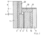
本発明を、本発明によるグレージングの1辺の断面概略図を示しているただ1つの添付図面を参照し、以下の例によって説明する。 The invention is illustrated by the following example with reference to the single accompanying drawing, which shows a schematic sectional view of one side of a glazing according to the invention.
(実施例)
図に示されているグレージングは、
404×404mmの寸法であって4mmの厚さを有する化学強化ソーダ石灰シリカガラスシート(1)、
332×332mmの寸法であって3mmの厚さを有する化学強化ソーダ石灰シリカガラスシート(3)、
346×346mmの寸法であって6mmの厚さを有する化学強化ソーダ石灰シリカガラスシート(5)、および
364×364mmの寸法であって3mmの厚さを有するポリカーボネート(11)
を備える。
(Example)
The glazing shown in the figure is
A chemically strengthened soda-lime-silica glass sheet (1) having dimensions of 404 × 404 mm and a thickness of 4 mm;
Chemically strengthened soda-lime-silica glass sheet (3) having dimensions of 332 × 332 mm and a thickness of 3 mm,
Chemically strengthened soda-lime-silica glass sheet (5) having dimensions of 346 × 346 mm and 6 mm, and polycarbonate (11) having dimensions of 364 × 364 mm and a thickness of 3 mm
Is provided.
これらのシートは全て、互いに中心を合わせられており、したがってシート(3)の縁は、全ての辺において、シート(1)の各辺からは36mmだけ、シート(5)の各辺からは7mmだけ後退しており、シート(5)の各辺は、ポリカーボネートシート(11)の各辺から9mmだけ後退している。 All these sheets are centered on each other, so the edges of the sheet (3) are only 36 mm from each side of the sheet (1) and 7 mm from each side of the sheet (5) on all sides. The sides of the sheet (5) are set back by 9 mm from the sides of the polycarbonate sheet (11).
シート(1)および(3)は、シート(1)の表面全体を覆っている厚さ0.76mmの熱可塑性ポリウレタン接着層(2)によって接続されている。 Sheets (1) and (3) are connected by a 0.76 mm thick thermoplastic polyurethane adhesive layer (2) covering the entire surface of sheet (1).
シート(3)および(5)は、2つのグレージングシートの少なくとも最も小さい表面(3)を覆っている厚さ1.14mmの標準的なポリビニルブチラール接着層(4)によって接続されている。 Sheets (3) and (5) are connected by a standard polyvinyl butyral adhesive layer (4) with a thickness of 1.14 mm covering at least the smallest surface (3) of the two glazing sheets.
シート(5)および(11)は、シート(5)および(11)の少なくとも最も小さい表面(5)を覆っている厚さ2.5mmの熱可塑性ポリウレタン接着層(10)によって接続されている。 Sheets (5) and (11) are connected by a 2.5 mm thick thermoplastic polyurethane adhesive layer (10) covering at least the smallest surface (5) of sheets (5) and (11).
強化インサート(20)が、グレージングシート(1)と同じ外寸を有し、幅が35mmであって厚さが2mmである鋼製フレームを形成している。強化インサート(20)の外縁は、強化インサート(20)が接着層(2)を介して接合されるように意図されているグレージングシート(1)の外縁に整列している。したがって、強化インサート(20)の内縁は、第2のグレージングシート(3)の縁から距離xにあり、ここでx=1mmである。 The reinforced insert (20) has the same outer dimensions as the glazing sheet (1), forming a steel frame having a width of 35 mm and a thickness of 2 mm. The outer edge of the reinforcing insert (20) is aligned with the outer edge of the glazing sheet (1) where the reinforcing insert (20) is intended to be joined via the adhesive layer (2). The inner edge of the reinforcing insert (20) is therefore at a distance x from the edge of the second glazing sheet (3), where x = 1 mm.
ポリカーボネートシート(11)の縁に対して、強化インサート(20)は、20mmである距離eだけ積層構造から露出しており、i=15mmだけ積層構造体へと挿入されている。 With respect to the edge of the polycarbonate sheet (11), the reinforcing insert (20) is exposed from the laminated structure by a distance e of 20 mm and is inserted into the laminated structure by i = 15 mm.
これらの構成要素を一体にして、所望の様相に整列させた後、100から140℃の間であるオートクレーブ内での積層体の組み立ての温度において流動できる或る量の熱可塑性ポリウレタン(30)が、強化インサート(20)と第3のグレージングシート(5)およびポリカーボネートシート(11)の縁との間に広がる空洞に配置される。したがって、この量は、自身の流動により、さらには温度および圧力の組み合わせの作用ゆえに組み立ての際に脱気をもたらすことによって、組み立て前の図に示されており、接着層(2)、強化インサート(20)の内縁、第2のグレージングシート(3)の縁、および接着層(4)によって境界付けられている空間など、空き空間の全体を満たすために充分である。この熱可塑性ポリウレタン(30)の量は、当然ながら、第3のグレージングシート(5)の縁のポリカーボネートシート(11)の縁に対するオフセットに依存する。一般に、このオフセットは、2.5から19.5mmの間であり、この場合には9mmである。 After these components are brought together and aligned in the desired manner, an amount of thermoplastic polyurethane (30) that can flow at the temperature of assembly of the laminate in an autoclave that is between 100 and 140 ° C. , Disposed in a cavity extending between the reinforcing insert (20) and the edges of the third glazing sheet (5) and the polycarbonate sheet (11). This amount is therefore shown in the figure before assembly by its own flow, and also by degassing during assembly due to the action of a combination of temperature and pressure, the adhesive layer (2), the reinforcing insert It is sufficient to fill the entire empty space, such as the inner edge of (20), the edge of the second glazing sheet (3), and the space bounded by the adhesive layer (4). The amount of this thermoplastic polyurethane (30) naturally depends on the offset of the edge of the third glazing sheet (5) relative to the edge of the polycarbonate sheet (11). In general, this offset is between 2.5 and 19.5 mm, in this case 9 mm.
この熱可塑性ポリウレタン(30)は、オートクレーブ内での積層体の組み立て温度では軟化しないカプセル材料(31)によって覆われる。ここで、カプセル材料(31)は、約180℃の軟化点を有するポリウレタンのテープである。通常は0.5から4mmの間であるこのテープ(31)の厚さは、この場合には1mmである。好ましくは、色付けされており、例えば黒色である。ショアA硬さは、85±5程度である。したがって、構造体を構成しているシートの整列の不良を矯正するための剛性、および下方の熱可塑性ポリウレタン(30)との協働においてそのような整列の不良に適合するための柔軟性の両者を、組み合わせている。熱可塑性ポリウレタン(30)が、カプセル材料(31)が一方では強化インサート(20)へと、他方ではポリカーボネートシート(11)の縁へと接合されるように保証している。
This thermoplastic polyurethane (30) is covered by an encapsulant (31) that does not soften at the assembly temperature of the laminate in the autoclave. Here, the capsule material (31) is a polyurethane tape having a softening point of about 180 ° C. The thickness of this tape (31), which is usually between 0.5 and 4 mm, is in this
カプセル材料(31)は、積層構造体へのいかなる水分の進入も防止しており、そのような進入が生じるならば、特にはポリカーボネートシート(11)の剥離を引き起こす原因となり得る。 The encapsulant (31) prevents any moisture ingress into the laminated structure, and if such intrusion occurs, it can in particular cause the polycarbonate sheet (11) to peel off.
このようにして、積層構造体が、100から140℃での従来からのオートクレーブプロセスを使用して組み立てられる。 In this way, the laminated structure is assembled using a conventional autoclave process at 100 to 140 ° C.
得られた積層構造体を、440±10m/sの速度の44口径マグナム弾で、図の垂直方向に対して45°の入射角で射撃した。構造体は、積層構造体が装備される装甲移動車両の車体と同じ方法で、強化インサート(20)およびカプセル材料(31)の自由面を当接させて金属フレームへと適用されていた。 The obtained laminated structure was shot with a 44 caliber magnum bullet at a speed of 440 ± 10 m / s at an incident angle of 45 ° with respect to the vertical direction of the figure. The structure was applied to the metal frame in the same way as the body of an armored mobile vehicle equipped with a laminated structure, with the free surfaces of the reinforcing insert (20) and the capsule material (31) in contact.
衝突の位置は、後述のように、強化インサート(20)の内縁から近い距離にあり、この距離に付された符号+が示しているとおり、強化インサート(20)の内縁から積層構造体の内部(すなわち、採光部分)へと向かった位置であった。 As will be described later, the position of the collision is at a short distance from the inner edge of the reinforcing insert (20), and as indicated by the symbol + attached to this distance, the inner edge of the laminated structure is from the inner edge of the reinforcing insert (20). It was the position that went to (that is, the daylighting part).
第1のグレージングユニットは、外周を巡って分布させた+25mmの位置への3発の連続した銃弾に耐えた。 The first glazing unit withstood three consecutive bullets to the +25 mm position distributed around the perimeter.
第2のグレージングユニットは、+25mmの位置への2発の射撃、およびその後の+30mmの位置への1発の射撃に耐えた。 The second glazing unit withstood two shots to the +25 mm position and one shot to the +30 mm position thereafter.
第3のグレージングユニットは、強化インサート(20)がi=17mの位置まで積層構造体へと挿入されている点においてのみ先の2つのグレージングユニットから相違しており、外周を巡って分布させた+15、+25、および+30mmの位置への3発の連続する射撃に耐えた。 The third glazing unit differs from the previous two glazing units only in that the reinforcing insert (20) is inserted into the laminated structure up to the position of i = 17 m, and is distributed around the outer periphery. Withstood three consecutive shots to +15, +25, and +30 mm positions.
強化インサート(20)がi=20mmの位置まで積層構造体へと挿入されている第4および第5のグレージングユニットは、+25mmの位置への2発の射撃、およびその後の+30mmの位置への2発の射撃に耐えた。 The fourth and fifth glazing units, in which the reinforced insert (20) is inserted into the laminated structure to the position i = 20 mm, have two shots to the +25 mm position and 2 to the +30 mm position thereafter. Withstood the shooting.
同じ射撃を、第3のグレージングシート(5)がカプセル材料(32)およびポリカーボネートシート(11)へと接続している接着層(10)まで延ばされている点で先のグレージングユニットと相違しているグレージングユニットにて行った。 The same shooting differs from the previous glazing unit in that the third glazing sheet (5) is extended to the adhesive layer (10) connected to the encapsulant (32) and the polycarbonate sheet (11). I went with a glazing unit.
上述の射撃と同じ射撃、特には+15mmから+25mmの間の射撃において、以下が観察された。 In the same shootings as described above, in particular between +15 mm and +25 mm, the following was observed:
弾丸の貫通はなかったが、保護されるべきユーザの存在する側へとグレージングの破片が飛散し、あるいは
1つ以上の弾丸が貫通した。
There was no bullet penetration, but glazing debris spattered to the side of the user to be protected, or one or more bullets penetrated.
これらの試験は、本発明の構造体の望ましい有効性を証明している。 These tests demonstrate the desired effectiveness of the structure of the present invention.
Claims (9)
接着層(2)を介して第1のガラスシート(1)へと接続されており、その縁が少なくとも1辺において第1のガラスシート(1)の縁から後退している第2のガラスシート(3)、
接着層(4)を介して第2のガラスシート(3)へと接続された第3のガラスシート(5)であって、第2のガラスシート(3)の縁が、少なくとも前記1辺において、第1のガラスシート(1)の縁からそれ自身が後退している第3のガラスシート(5)の縁からさらに後退している第3のガラスシート(5)、
場合によっては、1つ以上の接着層を介して第3のガラスシート(5)へと接続され、必要に応じては互いに接続される1つ以上の追加のガラスシート、
接着層(10)を介して第3のガラスシート(5)すなわち最後のガラスシートへと接続され、飛来物の衝撃を弱めるためのシート(11)、および
高防弾性の材料で製作され、少なくとも前記1辺において、第1および第3のガラスシート(1、5)の縁ならびに第2のガラスシート(3)の端面によって境界付けられた空洞の少なくとも一部を占めている強化インサート(20)
を順に備える積層構造体であって、
少なくとも前記1辺において、第3のガラスシート(5)および前記追加のガラスシートの縁が、飛来物の衝撃を弱めるために、シート(11)の縁から後退させられており、
強化インサート(20)と、第3のガラスシート(5)の端面と、飛来物の衝撃を弱めるためのシート(11)の縁との間の空間が、飛来物のエネルギーを吸収することができる材料(30、31)によって少なくとも部分的に占められており、
飛来物のエネルギーを吸収することができる材料(30、31)が、流動および積層構造体の組み立て時の脱気の保証が可能な材料(30)を介して、強化インサート(20)、第3のガラスシート(5)の端面、および飛来物の衝撃を弱めるためのシート(11)へと接合されており、
組み立ての際に流動する材料(30)を通さず、積層構造体への水分の進入に対して不透過性であるカプセル材料(31)が、少なくとも積層構造体の端面のうちの、飛来物の衝撃を弱めるためのシート(11)の端面と強化インサート(20)の少なくとも一部分との間に位置する部分をカプセル化することを特徴とする、積層構造体。 At least a first glass sheet (1),
The second glass sheet connected to the first glass sheet (1) via the adhesive layer (2), the edge of which is retracted from the edge of the first glass sheet (1) at least on one side (3),
A third glass sheet (5) connected to the second glass sheet (3) via an adhesive layer (4), wherein the edge of the second glass sheet (3) is at least on the one side A third glass sheet (5) that is further retracted from the edge of the third glass sheet (5), which is itself retracted from the edge of the first glass sheet (1),
In some cases, one or more additional glass sheets connected to the third glass sheet (5) via one or more adhesive layers, and optionally connected to each other,
Connected to the third glass sheet (5), that is, the last glass sheet via an adhesive layer (10), and made of a sheet (11) for reducing the impact of flying objects, and made of a highly ballistic material, at least A reinforced insert (20) occupying at least a portion of the cavity bounded by the edges of the first and third glass sheets (1, 5) and the end face of the second glass sheet (3) on the one side
In order,
At least on one side, the edges of the third glass sheet (5) and the additional glass sheet are retracted from the edges of the sheet (11) to reduce the impact of flying objects,
The space between the reinforcing insert (20), the end surface of the third glass sheet (5), and the edge of the sheet (11) for weakening the impact of the flying object can absorb the energy of the flying object. Is at least partly occupied by the material (30, 31);
The material (30, 31) capable of absorbing the energy of the flying object passes through the material (30) capable of guaranteeing deaeration during assembly of the flow structure and the laminated structure. To the end face of the glass sheet (5) and the sheet (11) for weakening the impact of flying objects,
The encapsulating material (31) that does not pass the material (30) that flows during assembly and is impermeable to the ingress of moisture into the laminated structure is at least of the projectiles on the end face of the laminated structure. A laminate structure characterized by encapsulating a portion located between an end face of a sheet (11) for weakening an impact and at least a portion of a reinforcing insert (20).
Applications Claiming Priority (3)
| Application Number | Priority Date | Filing Date | Title |
|---|---|---|---|
| FR0551755A FR2887489B1 (en) | 2005-06-24 | 2005-06-24 | SHEET STRUCTURE WITH BALISTIC RESISTANCE |
| FR0551755 | 2005-06-24 | ||
| PCT/FR2006/050625 WO2006136761A2 (en) | 2005-06-24 | 2006-06-23 | Ballistic resistant laminated structure |
Publications (2)
| Publication Number | Publication Date |
|---|---|
| JP2008543717A true JP2008543717A (en) | 2008-12-04 |
| JP5055274B2 JP5055274B2 (en) | 2012-10-24 |
Family
ID=35559280
Family Applications (1)
| Application Number | Title | Priority Date | Filing Date |
|---|---|---|---|
| JP2008517564A Expired - Fee Related JP5055274B2 (en) | 2005-06-24 | 2006-06-23 | Bulletproof laminated structure |
Country Status (13)
| Country | Link |
|---|---|
| US (1) | US7908958B2 (en) |
| EP (1) | EP1901917B1 (en) |
| JP (1) | JP5055274B2 (en) |
| KR (1) | KR101294665B1 (en) |
| CN (1) | CN101267939B (en) |
| BR (1) | BRPI0612485B1 (en) |
| DE (1) | DE212006000042U1 (en) |
| FR (1) | FR2887489B1 (en) |
| MX (1) | MX2007016438A (en) |
| RU (1) | RU2412918C2 (en) |
| UA (1) | UA92177C2 (en) |
| WO (1) | WO2006136761A2 (en) |
| ZA (1) | ZA200800587B (en) |
Cited By (1)
| Publication number | Priority date | Publication date | Assignee | Title |
|---|---|---|---|---|
| JP2010538238A (en) * | 2007-09-07 | 2010-12-09 | サン−ゴバン グラス フランス | High performance bulletproof glazing |
Families Citing this family (17)
| Publication number | Priority date | Publication date | Assignee | Title |
|---|---|---|---|---|
| US9162426B2 (en) * | 2006-08-30 | 2015-10-20 | Saxon Glass Technologies, Inc. | Transparent armor systems, methods for making and methods for using |
| DE202007001565U1 (en) * | 2007-02-02 | 2007-04-05 | Isoclima Gmbh | Armoured glass comprises at least one optically transparent sintered glass material made of aluminium oxynitride |
| WO2009048679A2 (en) * | 2007-08-03 | 2009-04-16 | Ermalovich Joseph M | Plastic encased multi-threat anti-ballistic material |
| US20120180940A1 (en) * | 2008-05-14 | 2012-07-19 | Yves Bader | Method to produce stab and ballistic resistant composite structures |
| DE102008028318A1 (en) * | 2008-06-13 | 2009-12-17 | Esw Gmbh | Bullet-resistant transparent layer composite and protective arrangement with a bullet-resistant transparent layer composite |
| US9157703B2 (en) | 2011-04-01 | 2015-10-13 | Am General Llc | Transparent Armor Structure |
| WO2013052182A2 (en) * | 2011-06-21 | 2013-04-11 | Bayer Materialscience Llc | Polycarbonate laminate for close-proximity blast events |
| CN102642349A (en) * | 2012-05-21 | 2012-08-22 | 云南呈达企业集团有限公司 | Novel bulletproof and anti-smashing composite glass |
| ES2465615T3 (en) | 2012-09-04 | 2020-01-03 | Isoclima Spa | Bulletproof window |
| EP2738512B1 (en) * | 2012-11-29 | 2019-02-20 | ISOCLIMA S.p.A. | Armoured window construction |
| US9383173B2 (en) * | 2013-07-22 | 2016-07-05 | The United States Of America As Represented By The Secretary Of The Army | Transparent armor construction |
| DE102015215065A1 (en) * | 2014-08-07 | 2016-02-11 | Ceramtec-Etec Gmbh | Shatterproof window |
| CN106494029A (en) * | 2016-11-16 | 2017-03-15 | 鲁利东 | A kind of high polymeric composite of KFTRZ is armoring |
| US9976306B1 (en) * | 2017-03-31 | 2018-05-22 | Aaron Carlson Corporation | Wall support structures and systems |
| WO2019149730A1 (en) * | 2018-01-31 | 2019-08-08 | Agc Glass Europe | Laminated glazing |
| CN112105500B (en) * | 2018-03-27 | 2023-06-23 | 皮尔金顿集团有限公司 | Laminated glass member |
| WO2019226495A2 (en) * | 2018-05-20 | 2019-11-28 | B.A. Glass & Safety Inc. | Unidirectional ballistic glass for defending against simultaneous multi-shot attack |
Citations (1)
| Publication number | Priority date | Publication date | Assignee | Title |
|---|---|---|---|---|
| JPH08188451A (en) * | 1994-06-16 | 1996-07-23 | Saint Gobain Vitrage | Thin film glass provided with outer peripheral belt and preparation of its glass |
Family Cites Families (15)
| Publication number | Priority date | Publication date | Assignee | Title |
|---|---|---|---|---|
| US2068082A (en) * | 1935-06-08 | 1937-01-19 | Duplate Corp | Laminated glass and process of making the same |
| US3380406A (en) * | 1965-04-28 | 1968-04-30 | Whittaker Corp | Composite design for transparent armour |
| IT999536B (en) * | 1972-09-29 | 1976-03-10 | Glaverbel | IMPACT RESISTANT GLASS |
| US3917891A (en) * | 1974-04-11 | 1975-11-04 | Asg Ind Inc | Fragmentation shield for impact resisting optical medium |
| FR2447273A1 (en) * | 1979-01-23 | 1980-08-22 | Brinks France Sa | COMPOSITE GLASS WITH HIGH IMPACT RESISTANCE |
| EP0746740A1 (en) * | 1993-06-03 | 1996-12-11 | MEDLIN, Richard C. | Improved lightweight armored vehicle and method of making same |
| CN2167989Y (en) * | 1993-07-22 | 1994-06-08 | 珠海经济特区兴业安全玻璃股份有限公司兴业汽车安全玻璃厂 | Super-thin cambered surface bullet-resistant glass for vehicles |
| DE4336321A1 (en) * | 1993-10-25 | 1995-04-27 | Ver Glaswerke Gmbh | Bulletproof bulletproof glass for motor vehicles |
| CN2247098Y (en) * | 1996-04-11 | 1997-02-12 | 卢予阳 | Composite transparent bullet-proof plate |
| CN2266508Y (en) * | 1996-06-21 | 1997-11-05 | 广东伦教汽车玻璃有限公司 | Improved bulletproof glass |
| FR2764841B1 (en) * | 1997-06-18 | 1999-07-16 | Saint Gobain Vitrage | ARMORED WINDOWS, ESPECIALLY FIXED OR MOBILE SIDE FOR MOTOR VEHICLE |
| DE19745248A1 (en) | 1997-10-13 | 1999-04-15 | Isoclima Gmbh | Armored glass sheet with a metal insert |
| DE19858082C5 (en) | 1998-12-16 | 2005-10-13 | Isoclima Gmbh | Armored glass pane for motor vehicle |
| FR2795365B1 (en) * | 1999-06-25 | 2002-07-12 | Saint Gobain Vitrage | ARMORED SHEET GLASS, PARTICULARLY FOR MOTOR VEHICLES |
| US7007585B2 (en) * | 2003-11-03 | 2006-03-07 | The United States Of America As Represented By The Secretary Of The Army | Multi-hit transparent armor system |
-
2005
- 2005-06-24 FR FR0551755A patent/FR2887489B1/en active Active
-
2006
- 2006-06-23 CN CN2006800225988A patent/CN101267939B/en active Active
- 2006-06-23 EP EP06778970.1A patent/EP1901917B1/en active Active
- 2006-06-23 JP JP2008517564A patent/JP5055274B2/en not_active Expired - Fee Related
- 2006-06-23 UA UAA200800820A patent/UA92177C2/en unknown
- 2006-06-23 DE DE212006000042U patent/DE212006000042U1/en not_active Expired - Lifetime
- 2006-06-23 MX MX2007016438A patent/MX2007016438A/en active IP Right Grant
- 2006-06-23 WO PCT/FR2006/050625 patent/WO2006136761A2/en active Application Filing
- 2006-06-23 RU RU2008102652/03A patent/RU2412918C2/en active
- 2006-06-23 BR BRPI0612485A patent/BRPI0612485B1/en active IP Right Grant
- 2006-06-23 KR KR1020077029930A patent/KR101294665B1/en active IP Right Grant
- 2006-06-23 US US11/993,629 patent/US7908958B2/en active Active
-
2008
- 2008-01-21 ZA ZA200800587A patent/ZA200800587B/en unknown
Patent Citations (1)
| Publication number | Priority date | Publication date | Assignee | Title |
|---|---|---|---|---|
| JPH08188451A (en) * | 1994-06-16 | 1996-07-23 | Saint Gobain Vitrage | Thin film glass provided with outer peripheral belt and preparation of its glass |
Cited By (1)
| Publication number | Priority date | Publication date | Assignee | Title |
|---|---|---|---|---|
| JP2010538238A (en) * | 2007-09-07 | 2010-12-09 | サン−ゴバン グラス フランス | High performance bulletproof glazing |
Also Published As
| Publication number | Publication date |
|---|---|
| FR2887489B1 (en) | 2007-08-03 |
| ZA200800587B (en) | 2008-11-26 |
| MX2007016438A (en) | 2008-03-07 |
| DE212006000042U1 (en) | 2008-02-14 |
| KR20080023223A (en) | 2008-03-12 |
| WO2006136761A2 (en) | 2006-12-28 |
| JP5055274B2 (en) | 2012-10-24 |
| US7908958B2 (en) | 2011-03-22 |
| RU2008102652A (en) | 2009-07-27 |
| UA92177C2 (en) | 2010-10-11 |
| WO2006136761A3 (en) | 2007-05-24 |
| BRPI0612485B1 (en) | 2017-05-23 |
| KR101294665B1 (en) | 2013-08-09 |
| BRPI0612485A2 (en) | 2012-10-02 |
| CN101267939A (en) | 2008-09-17 |
| CN101267939B (en) | 2013-03-27 |
| EP1901917A2 (en) | 2008-03-26 |
| FR2887489A1 (en) | 2006-12-29 |
| EP1901917B1 (en) | 2016-02-03 |
| RU2412918C2 (en) | 2011-02-27 |
| US20100132540A1 (en) | 2010-06-03 |
Similar Documents
| Publication | Publication Date | Title |
|---|---|---|
| JP5055274B2 (en) | Bulletproof laminated structure | |
| EP1800086B1 (en) | Armored glass composition with perimeter reinforcement | |
| JP6070969B2 (en) | Multilayer transparent lightweight safety glazing | |
| US8833233B2 (en) | Bullet-resistant transparent laminate composite and protection arrangement having a bullet-resistant transparent laminate composite | |
| US7318956B2 (en) | One way bullet-resistant transparent panel | |
| EP2699405B1 (en) | Light weight temperature resistant transparent laminate structure | |
| US20210379871A1 (en) | Transparent, shatterproof, bullet-resistant glazing with fire protection properties | |
| US20110177310A1 (en) | Projectile Resistant Transparent Laminate | |
| US20100300276A1 (en) | High-performance bulletproof glazing | |
| EP2363285A1 (en) | Glazing of laminated safety glass | |
| WO2008127351A2 (en) | Insulated bullet resistant glass | |
| KR101917024B1 (en) | Transparent bulletproof materials | |
| US11254103B2 (en) | Bullet-resistent insulating glazing unit | |
| WO2010036219A1 (en) | Anti-spall windows | |
| ES2667747T3 (en) | Procedure and construction kit for the manufacture and / or repair of a transparent composite glass | |
| CA2512927C (en) | Ballistic resistant devices and systems and methods of manufacture thereof | |
| WO2024063768A1 (en) | Impact-dampening, unidirectional multi-layered spalling-resistant ballistic glass | |
| WO2019008466A1 (en) | Multilayer laminate and method of production | |
| MX2007003689A (en) | Armored glass composition with perimeter reinforcement | |
| WO2005062932A2 (en) | One way bullet-resistant transparent panel meeting nij level iii standards and armor piercing bullt-resistant transparent panel |
Legal Events
| Date | Code | Title | Description |
|---|---|---|---|
| A621 | Written request for application examination |
Free format text: JAPANESE INTERMEDIATE CODE: A621 Effective date: 20090527 |
|
| A977 | Report on retrieval |
Free format text: JAPANESE INTERMEDIATE CODE: A971007 Effective date: 20120208 |
|
| A131 | Notification of reasons for refusal |
Free format text: JAPANESE INTERMEDIATE CODE: A131 Effective date: 20120214 |
|
| A521 | Request for written amendment filed |
Free format text: JAPANESE INTERMEDIATE CODE: A523 Effective date: 20120514 |
|
| TRDD | Decision of grant or rejection written | ||
| A01 | Written decision to grant a patent or to grant a registration (utility model) |
Free format text: JAPANESE INTERMEDIATE CODE: A01 Effective date: 20120724 |
|
| A01 | Written decision to grant a patent or to grant a registration (utility model) |
Free format text: JAPANESE INTERMEDIATE CODE: A01 |
|
| A61 | First payment of annual fees (during grant procedure) |
Free format text: JAPANESE INTERMEDIATE CODE: A61 Effective date: 20120730 |
|
| R150 | Certificate of patent or registration of utility model |
Free format text: JAPANESE INTERMEDIATE CODE: R150 Ref document number: 5055274 Country of ref document: JP Free format text: JAPANESE INTERMEDIATE CODE: R150 |
|
| FPAY | Renewal fee payment (event date is renewal date of database) |
Free format text: PAYMENT UNTIL: 20150803 Year of fee payment: 3 |
|
| R250 | Receipt of annual fees |
Free format text: JAPANESE INTERMEDIATE CODE: R250 |
|
| R250 | Receipt of annual fees |
Free format text: JAPANESE INTERMEDIATE CODE: R250 |
|
| S111 | Request for change of ownership or part of ownership |
Free format text: JAPANESE INTERMEDIATE CODE: R313113 |
|
| R350 | Written notification of registration of transfer |
Free format text: JAPANESE INTERMEDIATE CODE: R350 |
|
| R250 | Receipt of annual fees |
Free format text: JAPANESE INTERMEDIATE CODE: R250 |
|
| R250 | Receipt of annual fees |
Free format text: JAPANESE INTERMEDIATE CODE: R250 |
|
| R250 | Receipt of annual fees |
Free format text: JAPANESE INTERMEDIATE CODE: R250 |
|
| R250 | Receipt of annual fees |
Free format text: JAPANESE INTERMEDIATE CODE: R250 |
|
| R250 | Receipt of annual fees |
Free format text: JAPANESE INTERMEDIATE CODE: R250 |
|
| R250 | Receipt of annual fees |
Free format text: JAPANESE INTERMEDIATE CODE: R250 |
|
| LAPS | Cancellation because of no payment of annual fees |