JP2008542961A - Optical system - Google Patents
Optical system Download PDFInfo
- Publication number
- JP2008542961A JP2008542961A JP2008514240A JP2008514240A JP2008542961A JP 2008542961 A JP2008542961 A JP 2008542961A JP 2008514240 A JP2008514240 A JP 2008514240A JP 2008514240 A JP2008514240 A JP 2008514240A JP 2008542961 A JP2008542961 A JP 2008542961A
- Authority
- JP
- Japan
- Prior art keywords
- auxiliary
- spot
- optical
- record carrier
- optical system
- Prior art date
- Legal status (The legal status is an assumption and is not a legal conclusion. Google has not performed a legal analysis and makes no representation as to the accuracy of the status listed.)
- Pending
Links
Images


Classifications
-
- G—PHYSICS
- G11—INFORMATION STORAGE
- G11B—INFORMATION STORAGE BASED ON RELATIVE MOVEMENT BETWEEN RECORD CARRIER AND TRANSDUCER
- G11B7/00—Recording or reproducing by optical means, e.g. recording using a thermal beam of optical radiation by modifying optical properties or the physical structure, reproducing using an optical beam at lower power by sensing optical properties; Record carriers therefor
- G11B7/08—Disposition or mounting of heads or light sources relatively to record carriers
- G11B7/09—Disposition or mounting of heads or light sources relatively to record carriers with provision for moving the light beam or focus plane for the purpose of maintaining alignment of the light beam relative to the record carrier during transducing operation, e.g. to compensate for surface irregularities of the latter or for track following
- G11B7/0901—Disposition or mounting of heads or light sources relatively to record carriers with provision for moving the light beam or focus plane for the purpose of maintaining alignment of the light beam relative to the record carrier during transducing operation, e.g. to compensate for surface irregularities of the latter or for track following for track following only
- G11B7/0903—Multi-beam tracking systems
-
- G—PHYSICS
- G11—INFORMATION STORAGE
- G11B—INFORMATION STORAGE BASED ON RELATIVE MOVEMENT BETWEEN RECORD CARRIER AND TRANSDUCER
- G11B7/00—Recording or reproducing by optical means, e.g. recording using a thermal beam of optical radiation by modifying optical properties or the physical structure, reproducing using an optical beam at lower power by sensing optical properties; Record carriers therefor
- G11B7/08—Disposition or mounting of heads or light sources relatively to record carriers
- G11B7/09—Disposition or mounting of heads or light sources relatively to record carriers with provision for moving the light beam or focus plane for the purpose of maintaining alignment of the light beam relative to the record carrier during transducing operation, e.g. to compensate for surface irregularities of the latter or for track following
-
- G—PHYSICS
- G11—INFORMATION STORAGE
- G11B—INFORMATION STORAGE BASED ON RELATIVE MOVEMENT BETWEEN RECORD CARRIER AND TRANSDUCER
- G11B7/00—Recording or reproducing by optical means, e.g. recording using a thermal beam of optical radiation by modifying optical properties or the physical structure, reproducing using an optical beam at lower power by sensing optical properties; Record carriers therefor
- G11B7/08—Disposition or mounting of heads or light sources relatively to record carriers
- G11B7/085—Disposition or mounting of heads or light sources relatively to record carriers with provision for moving the light beam into, or out of, its operative position or across tracks, otherwise than during the transducing operation, e.g. for adjustment or preliminary positioning or track change or selection
-
- G—PHYSICS
- G11—INFORMATION STORAGE
- G11B—INFORMATION STORAGE BASED ON RELATIVE MOVEMENT BETWEEN RECORD CARRIER AND TRANSDUCER
- G11B7/00—Recording or reproducing by optical means, e.g. recording using a thermal beam of optical radiation by modifying optical properties or the physical structure, reproducing using an optical beam at lower power by sensing optical properties; Record carriers therefor
- G11B7/08—Disposition or mounting of heads or light sources relatively to record carriers
- G11B7/09—Disposition or mounting of heads or light sources relatively to record carriers with provision for moving the light beam or focus plane for the purpose of maintaining alignment of the light beam relative to the record carrier during transducing operation, e.g. to compensate for surface irregularities of the latter or for track following
- G11B7/0938—Disposition or mounting of heads or light sources relatively to record carriers with provision for moving the light beam or focus plane for the purpose of maintaining alignment of the light beam relative to the record carrier during transducing operation, e.g. to compensate for surface irregularities of the latter or for track following servo format, e.g. guide tracks, pilot signals
-
- G—PHYSICS
- G11—INFORMATION STORAGE
- G11B—INFORMATION STORAGE BASED ON RELATIVE MOVEMENT BETWEEN RECORD CARRIER AND TRANSDUCER
- G11B7/00—Recording or reproducing by optical means, e.g. recording using a thermal beam of optical radiation by modifying optical properties or the physical structure, reproducing using an optical beam at lower power by sensing optical properties; Record carriers therefor
- G11B7/08—Disposition or mounting of heads or light sources relatively to record carriers
- G11B7/09—Disposition or mounting of heads or light sources relatively to record carriers with provision for moving the light beam or focus plane for the purpose of maintaining alignment of the light beam relative to the record carrier during transducing operation, e.g. to compensate for surface irregularities of the latter or for track following
- G11B7/095—Disposition or mounting of heads or light sources relatively to record carriers with provision for moving the light beam or focus plane for the purpose of maintaining alignment of the light beam relative to the record carrier during transducing operation, e.g. to compensate for surface irregularities of the latter or for track following specially adapted for discs, e.g. for compensation of eccentricity or wobble
Abstract
本発明は,光記録担体上で半径方向のトラッキングを行う光学システムに関する。この光学システムは,同担体上で読取り可能な効果(ピット,マーク等)としての情報を読取り及び/又は記録するための主ビームと,半径方向のトラッキングのために使われる少なくとも二つの補助ビームとを照射することが出来る可動型の照射装置を含む。当該トラッキングは,主スポットに対して非対称に配置されている複数の補助スポットから反射された照射光により行われる。この光記録担体は,一つ以上の螺旋のトラック中に前記読取り可能な効果を含み,この一つ以上の螺旋は,一つ以上のガードバンドによって区切られている。第1及び第2のガードバンド中に位置している第1及び第2の補助ビームの反射光により半径方向のトラッキングを行うよう,この光学システムは適応されている。 The present invention relates to an optical system for performing radial tracking on an optical record carrier. This optical system comprises a main beam for reading and / or recording information as readable effects (pits, marks etc.) on the same carrier and at least two auxiliary beams used for radial tracking. Including a movable type irradiation device capable of irradiating the light source. The tracking is performed by irradiation light reflected from a plurality of auxiliary spots arranged asymmetrically with respect to the main spot. The optical record carrier includes the readable effect in one or more spiral tracks, the one or more spirals being delimited by one or more guard bands. The optical system is adapted to perform radial tracking with the reflected light of the first and second auxiliary beams located in the first and second guard bands.
Description
本発明は,光記録担体上に光学的に読取り可能な効果を記録及び/又は再生し,同光記録担体上で半径方向のトラッキングを行う光学システムに関する。本発明は他に,当該光記録担体上に光学的に読取り可能な効果を記録及び/又は再生する方法にも関する。 The present invention relates to an optical system that records and / or reproduces an optically readable effect on an optical record carrier and performs radial tracking on the optical record carrier. The invention also relates to a method for recording and / or reproducing an optically readable effect on the optical record carrier.
情報格納容量を増加させるという要求を満たすために,利用可能な光学媒体,即ちコンパクトディスク(CD),デジタル多用途ディスク(DVD)及びBlu-rayディスク(BD)は格納容量のコンスタントな改善を示している。これらの光学媒体において再生分解能は,再生照射の波長及び光学再生装置の開口数によってこれまで殆ど支配されてきた。しかしながら前記再生照射光の波長を短くすること,又は対応するレンズシステムの開口数を大きくすることは容易ではないので,記録密度を高める試みは記録媒体の改善及び/又は記録/再生方法の改善に際立って集中されてきた。 In order to meet the demand to increase information storage capacity, available optical media, namely compact disc (CD), digital versatile disc (DVD) and Blu-ray disc (BD), show a constant improvement in storage capacity. ing. The reproduction resolution in these optical media has been mostly governed so far by the wavelength of the reproduction irradiation and the numerical aperture of the optical reproduction apparatus. However, since it is not easy to shorten the wavelength of the reproduction irradiation light or increase the numerical aperture of the corresponding lens system, an attempt to increase the recording density is to improve the recording medium and / or the recording / reproducing method. It has been conspicuously concentrated.
特に,情報を記録するのに適する光学媒体に対して,二つの異なるアプローチが提案されてきた。一つはランド‐グルーブ・フォーマットで情報はトラックの溝(グルーブ)と当該溝の隣接部分(ランド)との両方に記録される。もう一つは,例えばBDディスク・フォーマットのようなグルーブのみのフォーマットで,情報はグルーブ中にのみ記録される。特に半径方向トラッキング及びトラック間/シンボル間の交差-書込み/交差-消去問題に関して,これらのフォーマットの両方が長所と短所とをもつ。 In particular, two different approaches have been proposed for optical media suitable for recording information. One is a land-groove format, and information is recorded in both a groove (land) of a track and an adjacent part (land) of the groove. The other is a groove-only format such as the BD disc format, and information is recorded only in the groove. Both of these formats have advantages and disadvantages, especially with respect to radial tracking and cross-track / symbol cross-write / cross-erase issues.
現在,チャネルビット長50nmをトラックピッチ240nmと組み合わせることによって到達する密度の限界は,前記BD型ディスクの容量では可能性としては現在の,媒体の情報層当り23-25-27GBから50GB迄増やせることを示している。しかしながら,現在の技術のディスクでは,トラックピッチの更なる狭小化対安定した半径方向のトラッキングの必要性との間の先天的な矛盾,及び有限な交差-書込み/交差-消去の問題につきあたってしまう。特に,安定な半径方向トラッキングに対するランド‐グルーブ・フォーマットの長所と,有限な交差-書込み/交差-消去問題に対するグルーブのみのフォーマットの長所との両方をもつ光学データの格納方法が故に望まれる。 Currently, the limit of density reached by combining channel bit length 50nm with track pitch 240nm can be increased from 23-25-27GB to 50GB per medium information layer, possibly with the capacity of the BD disc. Is shown. However, with current technology disks, there are inherent inconsistencies between the further narrowing of track pitch versus the need for stable radial tracking, and the problem of finite cross-write / cross-erase. End up. In particular, a method of storing optical data that has both the advantages of a land-groove format for stable radial tracking and the advantages of a groove-only format for finite cross-write / cross-erase problems is desirable.
近年,2次元のオプティカルストレージ(TwoDOS)が実証されてきている。例えばAlexander van der Lee等による応用物理学会誌日本版vol. 43, No 7B, 2004, p.4912-4914を参照。TwoDOSフォーマットにおいては,光担体上の幅広の螺旋に沿った平行した幾つかのデータ列として情報は書込まれ,当該データはレーザスポットのアレイを使って前記螺旋から平行して読出される。しかしながら,各々のレーザスポットが独立して制御されねばならず,従って複数のレーザ又はレーザキャビティを必要とするので追記型及び書換え型の媒体に対しては,上記は便利ではない。これは対応する光学装置を複雑にするであろうし,同装置のコストを増すことであろう。同様に,レーザの数,又はレーザのキャビティ数に比例して斯様な光学装置の熱放射が増大する。 In recent years, two-dimensional optical storage (TwoDOS) has been demonstrated. For example, see the Japan Society for Applied Physics vol. 43, No 7B, 2004, p.4912-4914 by Alexander van der Lee et al. In the TwoDOS format, information is written as several parallel data strings along a wide spiral on an optical carrier, and the data is read in parallel from the spiral using an array of laser spots. However, this is not convenient for write-once and rewritable media because each laser spot must be controlled independently and thus requires multiple lasers or laser cavities. This will complicate the corresponding optical device and will increase the cost of the device. Similarly, the thermal radiation of such an optical device increases in proportion to the number of lasers or the number of laser cavities.
ゆえに,改善された光学データの格納方法が有利であると思われ,特に,光記録担体上に光学的に読取り可能な効果を記録/再生するためのより効率の良い及び/又はより信頼性の高い光学システムが有利であろう。 Therefore, improved optical data storage methods would be advantageous, especially more efficient and / or more reliable for recording / reproducing optically readable effects on optical record carriers. A high optical system would be advantageous.
従って,一つ以上の上述の短所を,単独で又は何らかの組合せで軽減,緩和,又は取り除くことを本発明は好ましくは求めている。特に,光記録担体上に光学的に読取り可能な効果を信頼性良く記録,及び/又は再生することと,当該光記録担体の増加した格納容量との両方を持ってして従来技術の上記の問題を解決する光学システムを提供することが本発明の目的として理解されよう。 Accordingly, the present invention preferably seeks to alleviate, mitigate, or eliminate one or more of the above-mentioned disadvantages alone or in any combination. In particular, the above-mentioned prior art has both the reliable recording and / or reproduction of the optically readable effect on the optical record carrier and the increased storage capacity of the optical record carrier. It will be appreciated as an object of the present invention to provide an optical system that solves the problem.
本発明の第1の態様中で,光記録担体上に光学的に読取り可能な効果を記録及び/又は再生する光学システムを提供することにより,この目的及び幾つかの他の目的は達成され,当該システムは,
‐ 光記録担体中で読取り可能な効果として情報を読取るため,及び/又は同光記録担体上に読取り可能な効果として情報を記録するための主ビーム及びこれに対応する主スポットと,
半径方向トラッキングに使用可能な,第1の補助ビームと第2の補助ビームとを有する少なくとも二つの補助ビーム及びこれに対応する補助スポットとを照射できる可動型の光照射装置,及び
‐ 前記光記録担体から反射された照射を検知することができる光検知手段を有し,
当該光記録担体は一つ以上の螺旋のトラック中に読取り可能な効果を有するか,又は同光記録担体は前記効果を記録するのに適していて,前記一つ以上の螺旋はガードバンドによって区切られており,
当該光学システムは補助スポットから反射された照射からトラッキングを行うのに適しており,この補助スポットは主スポットに対して非対称に配置されている。
In the first aspect of the present invention, this object and some other objects are achieved by providing an optical system for recording and / or reproducing optically readable effects on an optical record carrier, The system
A main beam and corresponding main spot for reading information as an effect readable in the optical record carrier and / or for recording information as an effect readable on the optical record carrier;
A movable light irradiation device capable of irradiating at least two auxiliary beams having a first auxiliary beam and a second auxiliary beam and corresponding auxiliary spots, which can be used for radial tracking, and the optical recording Having light detection means capable of detecting the irradiation reflected from the carrier;
The optical record carrier has a readable effect in one or more spiral tracks, or the optical record carrier is suitable for recording the effect, and the one or more spirals are delimited by guard bands. Has been
The optical system is suitable for tracking from the illumination reflected from the auxiliary spot, which is arranged asymmetrically with respect to the main spot.
短いトラックピッチ,即ち短いトラック幅をもつ光記録担体上の情報を記録/再生することができる光学システムを容易に実現するためには,第1の態様に従った本発明は特に有利ではあるが排他的に有利であることはない。本発明による半径方向トラッキングはガードバンドで行われるので,より短いトラックピッチが半径方向トラッキングを危険に晒すことはない。1本の螺旋トラックフォーマットを持つ一般に使われている単独のオプティカルストレージシステムは,グルーブによって提供される半径方向のトラッキングと,トラックピッチを最小にしたいという望みとの間で先天的に矛盾している。主ビームが光記録担体上の所与のトラック中の読取り可能な効果としての情報を読取り及び/又は主ビームが光記録担体上の所与のトラック中に読取り可能な効果としての情報を記録する間に補助ビームはトラッキングを行うので,主スポットに対して非対称に配置されている補助スポットから反射された照射光からのトラッキングによる本光学システムにより,この矛盾は解決されている。光照射装置を可動させることによって,少なくとも主スポット及び補助スポットの幾つかの大きな半径方向の変位が,主スポット及び補助スポットの他のより小さな半径方向の変位に変換される。これゆえ,補助スポットの位置を制御することによって,主スポットの位置が大変厳密に制御される。主スポット及び補助スポットの位置は,例えば螺旋中の所与のトラック数とか,所与のトラックピッチ等々,所与の光記録担体に対して決められる。主ビームの光強度は大変大きいので読取り可能な効果の記録は記録モードにて行われ,他方,補助ビームの強度は大変小さいので補助スポット下に位置する光記録担体の当該部分は,この光学システムの記録モード又は再生モードのいずれにおいても補助スポットからの影響を受けることは無い。 In order to easily realize an optical system capable of recording / reproducing information on an optical record carrier having a short track pitch, ie a short track width, the present invention according to the first aspect is particularly advantageous. It is not exclusively advantageous. Since radial tracking according to the present invention is performed in a guard band, a shorter track pitch does not jeopardize radial tracking. A commonly used single optical storage system with a single spiral track format is inherently inconsistent between the radial tracking provided by the groove and the desire to minimize track pitch . The main beam reads information as a readable effect in a given track on the optical record carrier and / or the main beam records information as a readable effect in a given track on the optical record carrier Since the auxiliary beam performs tracking in the meantime, this inconsistency is solved by the present optical system based on tracking from the irradiation light reflected from the auxiliary spot arranged asymmetrically with respect to the main spot. By moving the light irradiator, at least some large radial displacements of the main spot and auxiliary spots are converted into other smaller radial displacements of the main spot and auxiliary spots. Therefore, by controlling the position of the auxiliary spot, the position of the main spot is controlled very strictly. The positions of the main spot and the auxiliary spot are determined for a given optical record carrier, for example a given number of tracks in the spiral or a given track pitch. Since the light intensity of the main beam is very high, the readable effect is recorded in the recording mode, while the intensity of the auxiliary beam is so low that this part of the optical record carrier located under the auxiliary spot is the optical system. In any of the recording mode and the reproduction mode, there is no influence from the auxiliary spot.
前記光照射装置の可動は回転,捻り,曲げ等のような動きでもよく,従ってトラック方向に対する補助スポットの半径方向の配置が変化出来る。 The light irradiation device may be moved by rotation, twisting, bending, and the like, so that the radial arrangement of the auxiliary spots with respect to the track direction can be changed.
補助スポットに対して主スポットを非対称に供するというコストに効果のある態様を促進するので,請求項2に規定された追加の特徴は好都合である。主スポットは補助スポットの間に置かれるか,又は補助スポットの一方の側に配置されてもよい。 The additional feature defined in claim 2 is advantageous as it facilitates a cost effective manner of subjecting the main spot asymmetrically to the auxiliary spot. The main spot may be placed between the auxiliary spots or arranged on one side of the auxiliary spot.
所与のガードバンド中に位置する第1の補助スポットに対して,異なるガードバンド中の第2の補助スポットの位置によって所与の螺旋内の所与のトラック上の主スポットの位置が高精度で制御されるのを前記光照射装置の角位置の小さな変化は促進するので,請求項3に規定された任意の特徴は好都合である。前記角位置の変化は,前記光照射装置の回転によって得られよう。
For the first auxiliary spot located in a given guard band, the position of the second auxiliary spot in a different guard band ensures that the position of the main spot on a given track in a given helix is accurate. The optional feature defined in
補助スポットと主スポットとの間の分離距離を制御することにより,螺旋のピッチがトラックピッチの整数倍である状況,及び螺旋のピッチがトラックピッチの整数倍ではない状況の両方に対して高い選択性を持つシステムが提供されるので,請求項4及び5に規定された任意の特徴は好都合である。 High control for both situations where the spiral pitch is an integer multiple of the track pitch and where the spiral pitch is not an integer multiple of the track pitch by controlling the separation distance between the auxiliary spot and the main spot The optional features defined in claims 4 and 5 are advantageous since a system is provided.
主スポットの位置が所与のトラックに追随するよう保たれるので,請求項6に規定された任意の特徴は好都合である。半径方向トラッキングは,第1の補助ビームが第1のガードバンド中に位置し,第2の補助ビームが第2のガードバンド中に位置している第1及び第2の補助ビームの反射された照射光を検知することによって得られる。プッシュプル(PP)法及び位相差検知(DPD)法等々のような技術を用いて,光学システムは半径方向トラッキングを行うことができる。 The optional feature defined in claim 6 is advantageous because the position of the main spot is kept to follow a given track. Radial tracking is reflected from the first and second auxiliary beams where the first auxiliary beam is located in the first guard band and the second auxiliary beam is located in the second guard band. It is obtained by detecting the irradiation light. Using techniques such as push-pull (PP) and phase difference detection (DPD) methods, the optical system can perform radial tracking.
第2の態様において,本発明の第1の態様に従った光学システムを動作させるための方法に,本発明は関する。使用状況では,前記トラッキングは補助スポットから反射された照射により行われ,当該補助スポットは主スポットに対して非対称に配置されている。 In a second aspect, the invention relates to a method for operating an optical system according to the first aspect of the invention. In use, the tracking is performed by irradiation reflected from the auxiliary spot, and the auxiliary spot is arranged asymmetrically with respect to the main spot.
第3の態様において,データ格納手段を持つ,少なくとも一つのコンピュータを有するコンピュータシステムが,本発明の第2の態様に従った光学システムを制御することを可能にするコンピュータプログラムに,本発明は関する。 In a third aspect, the invention relates to a computer program enabling a computer system having at least one computer with data storage means to control an optical system according to the second aspect of the invention. .
本発明の第2の態様の動作をコンピュータシステムにさせることが出来るコンピュータプログラムによって本発明が実行されるという本発明のこの態様は,特に有利ではあるが排他的に有利であることはない。従って,当該光学システムを制御しているコンピュータシステムにコンピュータプログラムを組込むことによって,本発明に従って動作するよういくつかの既知の光学システムが変更されることが期待される。例えば磁気媒体若しくは光学媒体,又はインターネットのようなコンピュータベースのネットワークを通じ,どのような種類のコンピュータで読取り可能な媒体でも,斯様なコンピュータプログラムは提供されることができる。 This aspect of the invention, in which the invention is carried out by a computer program capable of causing a computer system to perform the operation of the second aspect of the invention, is particularly advantageous but not exclusively advantageous. Accordingly, it is expected that some known optical systems will be modified to operate in accordance with the present invention by incorporating a computer program into the computer system controlling the optical system. Such a computer program can be provided on any kind of computer readable medium, eg via a magnetic or optical medium, or a computer based network such as the Internet.
本発明の第1,第2及び第3の態様は,各々いかなる他の態様とも組合わせることが出来る。本発明のこれらの及び他の態様は,これ以降に記述されている実施例を参照して明らかにされ,説明されよう。 Each of the first, second and third aspects of the invention can be combined with any other aspect. These and other aspects of the invention will be apparent from and elucidated with reference to the embodiments described hereinafter.
本発明の実施例は,添付の図面を参照して,例のみにて説明されよう。 Embodiments of the invention will now be described by way of example only with reference to the accompanying drawings.
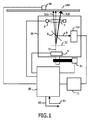
光学システム及び光記録担体100の実施例が図1に概観的に例示されている。保持手段30によってこの光記録担体100は固定され,回転させられる。
An embodiment of an optical system and
照射ビーム52によって情報を記録するのに適する材料を,前記光記録担体100は有する。この記録材料は,例えば光‐磁気タイプ,相変化タイプ,色素タイプ,Cu/Siのような金属合金,又はいかなる他の適切な材料であってもよい。情報は読取り可能な効果,即ち光学的に検知できる領域又は書換形媒体ではマークと呼ばれ,追記型媒体ではピットとも呼ばれる形で前記光記録担体100上に記録されるであろう。
The
この装置は,光ピックアップ(OPU)と呼ばれる光学ヘッド20を有し,この光学ヘッド20は,例えばステップモータのような可動手段21によって位置を変えることができる。この光学ヘッド20は,光検知システム101と,レーザのような照射源4と,ビームスプリッタ6と,対物レンズ7と,レンズ可動手段9とを有する。この光学ヘッド20はまた,照射ビーム52を少なくとも三つの部分52,52a,52b,即ち高強度の主ビームと二つの低強度の補助ビームとに分割することが出来るホログラムパターン又は回折格子のような光ビーム分割手段22を有する。同ビーム分割手段は可動型のビーム分割手段であって,例えば回転,捻り,曲げ等が可能であり,トラック方向に対して補助スポットの半径方向の位置が変化可能である。補助ビーム52a及び52bは,主ビーム52の同じ側(ここで図示されている)又は異なる側(図示されず)のいずれかにある異なる次数の回折ビームである。説明を明確にするために,照射ビーム52,52a,52bは前記ビーム分割手段6を通過したあとは3本の単一ビームとして示されているが,しかし例えばビーム分割手段22が回折格子である場合は,より多くの補助ビームが存在することであろう。同様に,反射された照射光8もまた一つ以上の成分,例えば三つのスポット52,52a,52bの反射,及びこれらの回折を有するが, 1本のビーム8のみが簡潔化のためにここでは示されている。
This apparatus has an
本実施例においては,ビーム分割手段(又は回折格子)と組合された照射源が光照射装置を構成している。これは,当該光照射装置を設計する際のコスト削減に有効な態様である。しかしながら,異なる強度でレーザを照射することが出来る,1列に並んだレーザダイオード・アレイのような等価な手段が想定されるであろう。前記ビーム分割手段(又は回折格子)を動かす代わりに,このアレイが動かされることが望ましい。 In this embodiment, the irradiation source combined with the beam splitting means (or diffraction grating) constitutes a light irradiation device. This is an effective mode for cost reduction when designing the light irradiation device. However, an equivalent means would be envisaged, such as an array of laser diodes that could irradiate the laser with different intensities. Instead of moving the beam splitting means (or diffraction grating), it is desirable to move the array.
光検知システム101の役割は,光記録担体100から反射された照射光8を電気信号に変換することである。従って,この光検知システム101は,プリプロセッサ11へ送られる一つ以上の電気出力信号を発生することが可能な一つ以上の光検知器を有するであろう。この光検知器はお互いに空間的に配置され,プリプロセッサ11中でフォーカスエラー(FE)及び半径方向のトラッキングエラー(RTE)を検知できるよう十分な時間分解能を持って配置されよう。このようにプリプロセッサ11は,フォーカスエラー(FE)信号及び半径方向のトラッキングエラー(RTE)信号をプロセッサ50へと送る。このプロセッサ50は,可動手段21,照射源4,レンズ可動手段9,プリプロセッサ11及び保持手段30への制御信号も出力することが出来る。同様にこのプロセッサ50は,61で示されたデータを外部から受け取ることが出来,そしてプロセッサ50は,60で示された読取りプロセスからのデータを外部へ出力できる。
The role of the
光検知システム101は,光記録担体100から読取られた情報を表す読取り信号又はRF信号を,プリプロセッサ11を通じてプロセッサ50へ送ることも出来る。プロセッサ50中でRF信号を低域通過フィルタに通すことにより,この読取り信号は中央開口(CA)信号に変換される。
The
フォトダイオード,CCD等の光検知素子を保持している光検知器は,プッシュプル(PP)法によるトラッキングを行うために二つの光検知素子を有していて,所望の半径方向の位置と実際の位置とからのエラー又は偏差を示す半径方向のエラー信号を発生するために,相対的な重み付けがこの二つの検知素子の間でされている。しかしながらこの光検知器は位相差検知(DPD)法に対しても適応することができ,従って当該部分は四つの光検知素子を有することも出来る。しかしながら斯様な実施例では,データがガードバンドにも提供されることを要する。同様に,この光検知器は,一対の補助スポットからの低域通過フィルタされた信号による半径方向のトラッキング用の1個の光検知素子から構成されることが出来る。 The photodetector that holds the photodetector such as a photodiode or CCD has two photodetectors for tracking by the push-pull (PP) method. Relative weighting is applied between the two sensing elements to generate a radial error signal indicating an error or deviation from the current position. However, this photodetector can also be adapted to the phase difference detection (DPD) method, so that the part can also have four photodetectors. However, such an embodiment requires that data be also provided to the guard band. Similarly, the photodetector can be comprised of a single photodetector for tracking in the radial direction with a low pass filtered signal from a pair of auxiliary spots.
図2及び図3には二つの特定の光記録担体のフォーマットが例示されている。これらのフォーマットは,本発明による光学システムと組合わせて使うのに良く適している。しかしながら本発明の原理はこれら二つのフォーマットに限定されるものではないことが強調されよう。 2 and 3 illustrate two specific optical record carrier formats. These formats are well suited for use with the optical system according to the present invention. However, it will be emphasized that the principles of the present invention are not limited to these two formats.
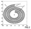
図2は第1の光記録担体のフォーマットの概観図である。このフォーマットにおいては,複数のトラック2が実質的に螺旋状に配置され,同光記録担体の中心位置3に対して実質的に同心円状に配置される。トラック2の各々は,実質的にグルーブ中に位置する(図示されず)光学的に読取り可能な効果を記録する及び/又は再生するようになっている。
FIG. 2 is an overview of the format of the first optical record carrier. In this format, a plurality of tracks 2 are arranged substantially spirally and are arranged substantially concentrically with respect to the
複数のトラック2が,当該光記録担体上のマルチトラック1の螺旋に隣接して存在している。ガードバンド5は何等データを含んでいないという事実に起因するストレージ容量の減少,又は幅広の螺旋のグルーブ中のデータ密度よりもガードバンド5中のデータ密度の方がより低いという事実に起因するストレージ容量の減少と,半径方向サーボシステムの複雑さとの間の妥協によって,幅広の螺旋1内のトラック2の本数は決定される。図2中のトラックの数は8本であるが,いかなる適切な数,特に2,3,4,5,6,7,8,9,10,11,12,13,14,15,16,17,18,19及び20も想定することが出来る。前記マルチトラックの螺旋1の巻きの間に在るトラッキング領域(ガードバンド)5が,光記録担体100からの半径方向トラッキングエラーを提供する。
A plurality of tracks 2 are present adjacent to the spiral of the multitrack 1 on the optical record carrier. Storage due to reduced storage capacity due to the fact that guard band 5 does not contain any data, or due to the fact that the data density in guard band 5 is lower than the data density in the wide spiral groove By compromising between capacity reduction and the complexity of the radial servo system, the number of tracks 2 in the wide spiral 1 is determined. The number of tracks in Figure 2 is eight, but any suitable number, in particular 2, 3, 4, 5, 6, 7, 8, 9, 10, 11, 12, 13, 14, 15, 16, 17, 18, 19 and 20 can also be envisaged. A tracking region (guard band) 5 present between the turns of the multitrack spiral 1 provides a radial tracking error from the
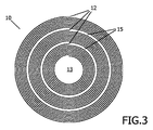
図3は,第2の光記録担体のフォーマットの概観図である。このフォーマットにおいては,複数のトラック12が実質的に螺旋状に配置され,同光記録担体の中心位置13に対して実質的に同心円状に配置される。トラック12の各々は,実質的にグルーブ中に位置する(図示されず)光学的に読取り可能な効果を記録する及び/又は再生するようになっている。各層の一本の螺旋が玉ねぎの構造をもつ複数の螺旋10が,光記録担体上の同心円状に連続した層12に在る。図3においては,丁度三つの連続した螺旋12が明確にするために示されているが,実際の光記録担体では螺旋12の数,又は「たまねぎの皮」の数は2と1,000,000との間で変わることであろう。前記螺旋12の間に在るトラッキング領域(ガードバンド)15が,光記録担体からの半径方向のトラッキングエラーを提供する。
FIG. 3 is an overview of the format of the second optical record carrier. In this format, a plurality of
前記マルチ螺旋1のトラック内,又は連続螺旋12のトラック内で,トラッキングには適切ではない殆どゼロのプッシュプル信号又は一般的に言えば,半径方向のトラッキングエラー信号が得られることであろう。しかしながらガードバンドにおいては,より大きなトラック空間が同バンドにあるため,グルーブ構造は著しく低い周波数成分をもち,補助スポットからのプッシュプルトラッキング信号は強く,同信号はガードバンド5,15の中央辺りで「S 字曲線」のような明確な半径方向トラッキングエラー信号を提供する。この結果,補助スポット52a,又は52bは,得られた半径方向トラッキング信号からガードバンド5及び15の中央を信頼性良くトラック出来る。
Within the multi-helix 1 track, or in the
Blu-rayの光学系では,160-200nmまでのガードバンドの幅が許容されることが出来る。螺旋中のトラックピッチは,半径方向トラッキングシステムに関して任意に選ぶことが可能である。書換形及び追記型のシステムにおいては,トラックをまたがった交差-書込み/交差-消去の効果を避けるために当該トラックピッチは十分に大きく選ぶのが望ましく,再生専用システムにおいては,ディスクの効率的なマスタリングを促進するためにトラックピッチは十分に大きいことが望ましい。 In Blu-ray optics, guard band widths of up to 160-200 nm can be tolerated. The track pitch in the spiral can be chosen arbitrarily for the radial tracking system. In rewritable and write-once systems, the track pitch should be chosen large enough to avoid cross-write / cross-erase effects across tracks. It is desirable that the track pitch be sufficiently large to facilitate mastering.
グルーブ幅とランドの幅の間(又は厳密な定義によっては逆の場合あり)の比であるデューテイサイクルが50%の状況では,ガードバンドの幅はトラックピッチの実質的には1.5倍に等しいことがある。光学システムと光記録担体フォーマット1及び10とがガードバンドに関して適している斯様な対称な配置では,トラックピッチ及びスポット52,52a,52bの半径方向への分離は本発明に関連して特別な長所を提供する。
In a situation where the duty cycle, which is the ratio between the groove width and the land width (or vice versa, depending on the exact definition) is 50%, the guard band width is substantially equal to 1.5 times the track pitch. Sometimes. In such a symmetrical arrangement in which the optical system and the optical record carrier formats 1 and 10 are suitable with respect to the guard band, the track pitch and the radial separation of the
光記録担体上の主スポットに対して非対称に置かれた補助スポットから反射された照射光によりトラッキングが行われる光照射装置の実施例を図4は例示する。 FIG. 4 illustrates an embodiment of a light irradiation device in which tracking is performed by irradiation light reflected from an auxiliary spot placed asymmetrically with respect to the main spot on the optical record carrier.
この光照射装置は,レーザのような照射源4及び回折格子22を有する。この回折格子は,一本のレーザビームを複数の角度的に分離したビームに分割する。当該ビームは高強度の0次のビーム400と,沢山の低強度の高次の補助ビーム(401a,401b,402a,402b)とに分割される。幾つかの高い次数の光(例えばガードバンド間に八つのトラックのあるディスクフォーマットでは1次及び8次)を除き,トラッキング信号の発生のためには十分な強度である非常に低い光強度にすべての高い次数の光がなるよう,この回折格子は設計されている。図4の例では5本のビームが生成されている。即ち,主の0次ビーム,二つの1次の補助ビーム,及び前記主ビームに関して対称に配置された二つの8次ビームである。トラッキング動作を実行するためには,主ビームに関してそれぞれ反対側に位置するか(404),又は主ビームに関して同じ側に位置する(403)8次のビームの1本と共に1次の補助ビームの1本が用いられる。従って,たとえ補助スポットが対称に配置されているとしても,異なる次数の補助スポットを選択することが出来,主スポットに関して非対称に配置された補助スポットから反射された照射光によってトラッキングが実行される。他の二つの補助ビームは,トラッキングに関与していないので単に無視される。
This light irradiation apparatus has an irradiation source 4 such as a laser and a
簡単な回折格子の設計と単純な製造とが実現されるので,この事例ではより低い次数の光が必要とされる主ビームの異なる側に補助ビームを持つことが通常は好ましい。ガードバンド間に8本のトラックをもつディスクフォーマットの同様の事例では,補助ビームが主ビームに対して同じ側に位置する場合,1次及び10次のオーダーのビームが必要とされることに注意する。 In this case, it is usually preferred to have an auxiliary beam on a different side of the main beam where lower order light is needed, because simple diffraction grating design and simple manufacturing are realized. Note that in a similar case of a disk format with 8 tracks between guard bands, if the auxiliary beam is located on the same side of the main beam, the 1st and 10th order beams are required. To do.
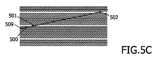
図5a,5b及び5cは,光記録担体の小さく切抜かれた区画を例示している。螺旋508中の異なるトラック位置503,504,509に主スポット500は導かれ,これに対応する補助スポット501及び502はガードバンドに配置されている。図5Aにおいて補助スポットは,隣接するガードバンド505,506に位置しており,図5Bにおいて,当該補助スポットは,1本のガードバンド分だけ分離されている二つのガードバンド505,507に位置している。一方図5Cにおいて当該補助スポットは,やはり隣接するガードバンド506及び507に位置しているが,しかし当該補助スポットは主スポットに対して同じ側にある。螺旋内のトラックのピッチよりも12倍大きな螺旋のピッチの増加を与えている11個のトラックが在る(この事例では各11個の通常のトラックの書込み後に,通常の幅の何もデータのない「空の」トラックを書込むことによりガードバンドは作られる)。
Figures 5a, 5b and 5c illustrate small cut sections of an optical record carrier. The
二つの補助スポットが主スポットに対して異なる側に置かれている図5A及び図5Bの状況においては,主スポット及び二つの補助スポットは,適切な回折率の回折格子を使うことにより補助スポット501と補助スポット502との間の距離が,主スポットと補助スポット501との間の距離よりも12倍大きくなるよう作られている。この事例において,図5A で示されているように,二つの補助スポットが隣接するガードバンド上にある場合は,主ビームは同螺旋内のトラック#1,503上に正確に位置している。二つの補助スポットが主スポットの同じ側に位置している,図5Cに示される状況においては,主スポットと二つの補助スポットとは,主スポット500と補助スポット501との間の距離が,二つの補助スポット501と502との間の距離よりも12倍大きくなるよう生成される。
In the situation of FIGS. 5A and 5B where the two auxiliary spots are located on different sides with respect to the main spot, the main spot and the two auxiliary spots are added to the
図5A 及び図5Bは,主スポットが異なるトラックに位置している状況を例示している。 5A and 5B illustrate the situation where the main spots are located on different tracks.
主スポットをトラック#2,504上へ位置させるためには,図5A に例示されているように補助スポット501が同一のガードバンド上に保持されている間,補助スポット502は図5Bに示されているように上方の次のガードバンド507へ移動,又は配置される。これは例えば光ピックアップ中の回折格子を回転させることにより達成される。二つの補助スポット間の距離が螺旋のピッチよりも著しく大きい場合,即ちトラック方向に対する補助スポットを結んだ線の回折格子の傾き角αがSin(α)=αなる近似が成立するくらいに十分に小さい場合,主スポットは螺旋内のトラック#2上に位置するであろう。実際に使われている光記録担体/光学システムのジオメトリでは,上記の小さい角の要件は通常は満たされている。
In order to position the main spot on track # 2,504,
補助スポットを異なるガードバンドへ移動させるための回折格子の回転,又は他の等価な手段は,光検知器上に反射されたスポットもまた当該光検知器上で僅かに移動されるようにする。これはトラッキング信号の僅かなオフセットになる。このオフセットの在る状況は,「現状として」是認されるか,又は当該移動量が訂正されるかのどちらかであろう。訂正の選択肢の1つは,回折格子の回転に合わせて当該光検知器を回転させることである。他の選択肢は,電気的なオフセット補償を用いることであり,当該オフセットレベルが当該回折格子の角度の関数として測定され,その後トラッキングの間,信号から減算される。 Rotation of the diffraction grating, or other equivalent means, to move the auxiliary spot to a different guard band causes the spot reflected on the photodetector to also be moved slightly on the photodetector. This is a slight offset of the tracking signal. The situation where this offset exists will either be approved "as is" or the amount of movement will be corrected. One of the correction options is to rotate the photodetector as the diffraction grating rotates. Another option is to use electrical offset compensation, where the offset level is measured as a function of the grating angle and then subtracted from the signal during tracking.
前記補助スポット501に対して前記補助スポット502を更に上方へ移動させる(図示されず)ことにより,主スポットを幅広の螺旋内のいかなる所与のトラック上にも位置させることが出来る。
By moving the
二つの補助スポットが主スポットに対して異なる側に位置する図5A及び図5Bに示される状況においては,主スポットと補助スポット501との間の分離距離にまたがるトラックの本数の整数倍に実質的に等しい主スポットと補助スポット502との間の距離をもつことにより,あるトラック上の主スポットの位置決めに関してより良い選択肢が得られる。例えば,主スポットと補助スポット502との間の距離は,主スポットと補助スポット501との間の距離よりもN*11倍大きくすることが出来る(Nは整数)。この主スポットを1トラックだけ上方へ移動させるには,補助スポット502がN個のガードバンド分だけ上へ動かされることが望ましい。螺旋のピッチが幅広の螺旋内のトラックピッチの整数倍ではない場合は,より高度な選択肢をもつ斯様なシステムもまた適用されることが出来る。
In the situation shown in FIGS. 5A and 5B where the two auxiliary spots are located on different sides of the main spot, it is substantially equal to an integral multiple of the number of tracks spanning the separation distance between the main spot and the
二つの補助スポットが主スポットと同じ側に位置している図5Cに示される状況においては,あるトラック上に主スポットの位置を決めることについてのより良い選択肢さえ同様の手段によって得られる。この状況では,補助スポット501と補助スポット502との間の距離が主スポットと補助スポット501との間の分離距離にまたがるトラック本数の整数倍に実質的に等しいことが望ましい。
In the situation shown in FIG. 5C where the two auxiliary spots are located on the same side as the main spot, even a better option for locating the main spot on a track is obtained by similar means. In this situation, it is desirable that the distance between the
ディスクのジオメトリの詳細は知られているので,補助スポットの移動に対応した主スポットの位置は予め決められることが出来る。異なる競合するフォーマットが存在する状況においては,システムは所与のフォーマットを認知し,この特定のフォーマットに従って補助スポットを移動させる。 Since the details of the geometry of the disc are known, the position of the main spot corresponding to the movement of the auxiliary spot can be predetermined. In situations where there are different competing formats, the system recognizes the given format and moves the auxiliary spot according to this particular format.
所与の実施例において,複数の補助スポットの独立した動きは,当該補助スポットに対する二つの独立したトラッキングシステムと組合せた可動型の回折格子によって得られる。第1の補助スポットの半径方向の位置決めは,通常の1個のスポットの光学系におけるのと同様の手段(ピックアップヘッド及び/又は対物レンズを動かすことによる)によって得られ,この第1の補助スポットを,選択したガードバンド上に保持したまま回折格子を回転させることによって第2の補助スポットの半径方向の位置決めを行うことができる。 In a given embodiment, independent movement of a plurality of auxiliary spots is obtained by a movable diffraction grating combined with two independent tracking systems for the auxiliary spots. The radial positioning of the first auxiliary spot is obtained by the same means (by moving the pick-up head and / or objective lens) as in the normal one-spot optical system. Can be positioned in the radial direction by rotating the diffraction grating while being held on the selected guard band.
使用の際は,第1の補助スポットを特定のガードバンド上に位置させることにより所望の螺旋が選択され,第1の補助スポットに対して一定数のガードバンド分だけ離れたガードバンドに第2の補助スポットを位置させることによって,この螺旋内の所望のトラックが選択される。 In use, the desired spiral is selected by positioning the first auxiliary spot on a specific guard band, and the second auxiliary band is separated from the first auxiliary spot by a certain number of guard bands. By positioning the auxiliary spot, the desired track in this spiral is selected.
本発明は特定の実施例に関連させて記述されてきたが,これはここで述べた特定の形に限定することを意図しているわけではない。むしろ,本発明の範囲は添付の請求項によってのみ限定される。請求項中においては,有するという言葉は他の要素,又はステップの存在を排除するものではない。加えて,各々の特徴が,複数の異なる請求項に含まれるかもしれないが,これらは都合良く組み合わせることができ,異なる請求項中に含まれるということは,各特徴の組合わせは実現可能ではない,及び/又は好適ではないと意味してはいない。加えるに,単数の引用は複数を排除するものではない。従って,「a」,「an」,「第1の」,「第2の」等々の引用は複数を除外するものではない。更に請求項中の参照記号は範囲を限定するものとして解釈されるべきではない。 Although the present invention has been described in connection with specific embodiments, it is not intended to be limited to the specific form set forth herein. Rather, the scope of the present invention is limited only by the accompanying claims. In the claims, the word having does not exclude the presence of other elements or steps. In addition, each feature may be included in a number of different claims, but they can be conveniently combined and included in different claims, so that a combination of features is not feasible. It does not mean none and / or unsuitable. In addition, singular citations do not exclude a plurality. Thus, references to “a”, “an”, “first”, “second”, etc. do not exclude a plurality. Furthermore, reference signs in the claims shall not be construed as limiting the scope.
Claims (9)
‐ 前記光記録担体中で読取り可能な効果として情報を読取るため,及び/又は前記光記録担体上に読取り可能な効果として情報を記録するための主ビーム及びこれに対応する主スポットと,
半径方向トラッキングに使用可能な,第1の補助ビームと第2の補助ビームとを有する少なくとも二つの補助ビーム及びこれに対応する補助スポットとを照射できる可動型の光照射装置,及び
‐ 前記光記録担体から反射された照射光を検知することができる光検知手段を有し,
前記光記録担体は一つ以上の螺旋のトラック中に読取り可能な効果を有するか,又は前記光記録担体は前記効果を記録し,前記一つ以上の螺旋はガードバンドによって区切られており,
当該光学システムは補助スポットから反射された照射光によってトラッキングを行い,この補助スポットは主スポットに対して非対称に配置されている光学システム。 An optical system for recording and / or reproducing an optically readable effect on an optical record carrier, the optical system comprising:
A main beam and corresponding main spot for reading information as an effect readable in the optical record carrier and / or for recording information as an effect readable on the optical record carrier;
A movable light irradiation device capable of irradiating at least two auxiliary beams having a first auxiliary beam and a second auxiliary beam and corresponding auxiliary spots, which can be used for radial tracking, and the optical recording Having light detection means capable of detecting the irradiation light reflected from the carrier;
The optical record carrier has a readable effect in one or more spiral tracks, or the optical record carrier records the effect, and the one or more spirals are delimited by a guard band;
The optical system is an optical system that performs tracking by irradiation light reflected from an auxiliary spot, and the auxiliary spot is arranged asymmetrically with respect to the main spot.
‐ 光記録担体中で読取り可能な効果として情報を読取るため,及び/又は前記光記録担体上に読取り可能な効果として情報を記録するための主ビーム及びこれに対応する主スポットと,
半径方向トラッキングに使用可能な,第1の補助ビームと第2の補助ビームとを有する少なくとも二つの補助ビーム及びこれに対応する補助スポットとを照射できる可動型の光照射装置,及び
‐ 前記光記録担体から反射された照射光を検知することができる光検知手段を有し,
前記光記録担体は一つ以上の螺旋のトラック中に読取り可能な効果を有するか,又は前記光記録担体は前記効果を記録し,前記一つ以上の螺旋はガードバンドによって区切られており,
使用の際は,前記主スポットに対して非対称に配置されている補助スポットから反射された照射光によってトラッキングが行われる方法。 A method of operating an optical system for recording and / or reproducing optically readable effects on an optical record carrier, the system comprising:
A main beam and a corresponding main spot for reading information as an effect readable in the optical record carrier and / or for recording information as an effect readable on the optical record carrier;
A movable light irradiation device capable of irradiating at least two auxiliary beams having a first auxiliary beam and a second auxiliary beam and corresponding auxiliary spots, which can be used for radial tracking, and the optical recording Having light detection means capable of detecting the irradiation light reflected from the carrier;
The optical record carrier has a readable effect in one or more spiral tracks, or the optical record carrier records the effect, and the one or more spirals are delimited by a guard band;
In use, the tracking is performed by the irradiation light reflected from the auxiliary spot arranged asymmetrically with respect to the main spot.
Applications Claiming Priority (2)
| Application Number | Priority Date | Filing Date | Title |
|---|---|---|---|
| EP05104680 | 2005-05-31 | ||
| PCT/IB2006/051533 WO2006129213A2 (en) | 2005-05-31 | 2006-05-16 | Optical system |
Publications (2)
| Publication Number | Publication Date |
|---|---|
| JP2008542961A true JP2008542961A (en) | 2008-11-27 |
| JP2008542961A5 JP2008542961A5 (en) | 2009-07-30 |
Family
ID=37177823
Family Applications (1)
| Application Number | Title | Priority Date | Filing Date |
|---|---|---|---|
| JP2008514240A Pending JP2008542961A (en) | 2005-05-31 | 2006-05-16 | Optical system |
Country Status (7)
| Country | Link |
|---|---|
| US (1) | US20080212448A1 (en) |
| EP (1) | EP1891633A2 (en) |
| JP (1) | JP2008542961A (en) |
| KR (1) | KR20080021052A (en) |
| CN (1) | CN101189668A (en) |
| TW (1) | TW200717483A (en) |
| WO (1) | WO2006129213A2 (en) |
Families Citing this family (5)
| Publication number | Priority date | Publication date | Assignee | Title |
|---|---|---|---|---|
| WO2006038154A1 (en) * | 2004-10-08 | 2006-04-13 | Koninklijke Philips Electronics N.V. | An optical record carrier |
| US20080247296A1 (en) * | 2005-09-30 | 2008-10-09 | Koninklijke Philips Electronics, N.V. | Optical Storage Disk and System Comprising a Disk with Non-Uniformly Spaced Tracks |
| US20080247288A1 (en) * | 2005-09-30 | 2008-10-09 | Koninklijke Philips Electronics, N.V. | Optical Disk Drive and Tracking Error Detection Method For an Optical Disk Drive |
| EP2200027A1 (en) * | 2008-12-22 | 2010-06-23 | Thomson Licensing | Optical disc, mastering method and apparatus for reading of respective data |
| US9965250B2 (en) * | 2011-12-07 | 2018-05-08 | Quintessencelabs Pty Ltd. | Integrated quantum-random noise generator using quantum vacuum states of light |
Citations (5)
| Publication number | Priority date | Publication date | Assignee | Title |
|---|---|---|---|---|
| JPH02282930A (en) * | 1989-04-24 | 1990-11-20 | Sony Corp | Optical recording and/or reproducing device |
| JPH0482021A (en) * | 1990-07-23 | 1992-03-16 | Mitsubishi Electric Corp | Optical recording and reproducing device |
| JPH04325934A (en) * | 1991-04-25 | 1992-11-16 | Nec Home Electron Ltd | Optical disk recording method and optical disk device |
| JPH052762A (en) * | 1991-06-26 | 1993-01-08 | Mitsubishi Electric Corp | Optical recording and reproducing device |
| JP2001110071A (en) * | 1999-10-12 | 2001-04-20 | Pioneer Electronic Corp | Information recorder and information reproducing device |
Family Cites Families (16)
| Publication number | Priority date | Publication date | Assignee | Title |
|---|---|---|---|---|
| JPS54146613A (en) * | 1978-05-10 | 1979-11-16 | Hitachi Ltd | Optical head |
| DE3323007C1 (en) * | 1983-06-25 | 1984-06-28 | Deutsche Thomson-Brandt Gmbh, 7730 Villingen-Schwenningen | Tracking system with an optical pickup for an audio or video disc player |
| US4720825A (en) * | 1984-02-06 | 1988-01-19 | Asahi Kogaku Kogyo Kabushiki Kaisha | Optical data reproducing devices having improved trick play capability |
| DE3714804A1 (en) * | 1987-05-04 | 1988-11-17 | Siemens Ag | Optical information storage disc |
| JPH01269240A (en) * | 1988-04-20 | 1989-10-26 | Csk Corp | Optical recording device |
| JP2651454B2 (en) * | 1989-05-18 | 1997-09-10 | 株式会社アサカ | Tracking error detector of multi-beam optical disk drive |
| JPH0354733A (en) * | 1989-07-21 | 1991-03-08 | Sony Corp | Optical recording and/or reproducing device |
| NL9000282A (en) * | 1990-02-06 | 1991-09-02 | Philips Nv | OPTICAL SCANNING DEVICE WITH MULTIPLE SCANNING SPOTS. |
| JP2923331B2 (en) * | 1990-06-12 | 1999-07-26 | オリンパス光学工業株式会社 | Optical recording medium and reproducing apparatus therefor |
| JP3155373B2 (en) * | 1992-10-01 | 2001-04-09 | パイオニア株式会社 | Method of reading recorded signal from optical disk |
| JPH09161273A (en) * | 1995-12-07 | 1997-06-20 | Matsushita Electric Ind Co Ltd | Optical disk reproducing device |
| US6088308A (en) * | 1998-02-13 | 2000-07-11 | International Business Machines Corporation | System for creating, reading and writing on rotatable information storage media, a tracking circuit for providing positioning information |
| JP3988343B2 (en) * | 1999-12-28 | 2007-10-10 | ソニー株式会社 | Optical pickup device, optical disk device, and track discrimination signal detection method |
| JP4151313B2 (en) * | 2002-06-03 | 2008-09-17 | 株式会社日立製作所 | Optical regenerator |
| WO2005024798A2 (en) * | 2003-09-11 | 2005-03-17 | Koninklijke Philips Electronics N.V. | Tracking method, recording means and a recorder for an optical disc |
| WO2006038154A1 (en) * | 2004-10-08 | 2006-04-13 | Koninklijke Philips Electronics N.V. | An optical record carrier |
-
2006
- 2006-05-16 KR KR1020077030239A patent/KR20080021052A/en not_active Application Discontinuation
- 2006-05-16 US US11/915,433 patent/US20080212448A1/en not_active Abandoned
- 2006-05-16 EP EP06755991A patent/EP1891633A2/en not_active Withdrawn
- 2006-05-16 CN CNA2006800193811A patent/CN101189668A/en active Pending
- 2006-05-16 WO PCT/IB2006/051533 patent/WO2006129213A2/en not_active Application Discontinuation
- 2006-05-16 JP JP2008514240A patent/JP2008542961A/en active Pending
- 2006-05-26 TW TW095118870A patent/TW200717483A/en unknown
Patent Citations (5)
| Publication number | Priority date | Publication date | Assignee | Title |
|---|---|---|---|---|
| JPH02282930A (en) * | 1989-04-24 | 1990-11-20 | Sony Corp | Optical recording and/or reproducing device |
| JPH0482021A (en) * | 1990-07-23 | 1992-03-16 | Mitsubishi Electric Corp | Optical recording and reproducing device |
| JPH04325934A (en) * | 1991-04-25 | 1992-11-16 | Nec Home Electron Ltd | Optical disk recording method and optical disk device |
| JPH052762A (en) * | 1991-06-26 | 1993-01-08 | Mitsubishi Electric Corp | Optical recording and reproducing device |
| JP2001110071A (en) * | 1999-10-12 | 2001-04-20 | Pioneer Electronic Corp | Information recorder and information reproducing device |
Also Published As
| Publication number | Publication date |
|---|---|
| US20080212448A1 (en) | 2008-09-04 |
| TW200717483A (en) | 2007-05-01 |
| CN101189668A (en) | 2008-05-28 |
| WO2006129213A3 (en) | 2007-03-08 |
| WO2006129213A2 (en) | 2006-12-07 |
| KR20080021052A (en) | 2008-03-06 |
| EP1891633A2 (en) | 2008-02-27 |
Similar Documents
| Publication | Publication Date | Title |
|---|---|---|
| EP1605448B1 (en) | Optical head, optical drive apparatus, and method for generating tracking error signal | |
| KR100756299B1 (en) | Optical recording device, optical head device, optical disc driving device, tracking controlling method therefor, and optical disc | |
| US8416656B2 (en) | Reproducing method and reproducing apparatus | |
| JP2008542961A (en) | Optical system | |
| US8259558B2 (en) | Optical storage medium and apparatus for reading of respective data | |
| JP4996353B2 (en) | Optical pickup and optical information recording / reproducing apparatus | |
| KR20080021120A (en) | An optical system with 3 spot radial tracking | |
| US20090279408A1 (en) | Optical data recording/reproducing system picking up multiple tracks between guard bands | |
| JP4379398B2 (en) | Disk drive device and control method thereof | |
| JP2010040148A (en) | Information recording medium and information recording and reproducing apparatus | |
| JP2012226809A (en) | Optical recording medium and drive unit | |
| JP2011258251A (en) | Optical pickup and optical disk device | |
| US20100177624A1 (en) | Optical system with a number of radiation sources | |
| US20080232208A1 (en) | High Frequency Central Aperture Tracking | |
| KR100619050B1 (en) | Method of recording information on hologram memory medium | |
| JP4666664B2 (en) | Optical pickup device and optical recording medium information reproducing device | |
| US20090196153A1 (en) | Tracking error signal generation method and optical disc apparatus |
Legal Events
| Date | Code | Title | Description |
|---|---|---|---|
| A521 | Request for written amendment filed |
Free format text: JAPANESE INTERMEDIATE CODE: A523 Effective date: 20090515 |
|
| A621 | Written request for application examination |
Free format text: JAPANESE INTERMEDIATE CODE: A621 Effective date: 20090515 |
|
| A977 | Report on retrieval |
Free format text: JAPANESE INTERMEDIATE CODE: A971007 Effective date: 20110113 |
|
| A131 | Notification of reasons for refusal |
Free format text: JAPANESE INTERMEDIATE CODE: A131 Effective date: 20110201 |
|
| A02 | Decision of refusal |
Free format text: JAPANESE INTERMEDIATE CODE: A02 Effective date: 20110628 |