JP2008536446A - Method and apparatus for video encoding and decoding - Google Patents
Method and apparatus for video encoding and decoding Download PDFInfo
- Publication number
- JP2008536446A JP2008536446A JP2008506465A JP2008506465A JP2008536446A JP 2008536446 A JP2008536446 A JP 2008536446A JP 2008506465 A JP2008506465 A JP 2008506465A JP 2008506465 A JP2008506465 A JP 2008506465A JP 2008536446 A JP2008536446 A JP 2008536446A
- Authority
- JP
- Japan
- Prior art keywords
- signal data
- video signal
- pred
- video
- unique
- Prior art date
- Legal status (The legal status is an assumption and is not a legal conclusion. Google has not performed a legal analysis and makes no representation as to the accuracy of the status listed.)
- Pending
Links
Images


Classifications
-
- H—ELECTRICITY
- H04—ELECTRIC COMMUNICATION TECHNIQUE
- H04N—PICTORIAL COMMUNICATION, e.g. TELEVISION
- H04N19/00—Methods or arrangements for coding, decoding, compressing or decompressing digital video signals
- H04N19/60—Methods or arrangements for coding, decoding, compressing or decompressing digital video signals using transform coding
- H04N19/61—Methods or arrangements for coding, decoding, compressing or decompressing digital video signals using transform coding in combination with predictive coding
-
- H—ELECTRICITY
- H04—ELECTRIC COMMUNICATION TECHNIQUE
- H04N—PICTORIAL COMMUNICATION, e.g. TELEVISION
- H04N19/00—Methods or arrangements for coding, decoding, compressing or decompressing digital video signals
- H04N19/10—Methods or arrangements for coding, decoding, compressing or decompressing digital video signals using adaptive coding
- H04N19/102—Methods or arrangements for coding, decoding, compressing or decompressing digital video signals using adaptive coding characterised by the element, parameter or selection affected or controlled by the adaptive coding
- H04N19/103—Selection of coding mode or of prediction mode
- H04N19/105—Selection of the reference unit for prediction within a chosen coding or prediction mode, e.g. adaptive choice of position and number of pixels used for prediction
-
- H—ELECTRICITY
- H04—ELECTRIC COMMUNICATION TECHNIQUE
- H04N—PICTORIAL COMMUNICATION, e.g. TELEVISION
- H04N19/00—Methods or arrangements for coding, decoding, compressing or decompressing digital video signals
- H04N19/10—Methods or arrangements for coding, decoding, compressing or decompressing digital video signals using adaptive coding
- H04N19/102—Methods or arrangements for coding, decoding, compressing or decompressing digital video signals using adaptive coding characterised by the element, parameter or selection affected or controlled by the adaptive coding
- H04N19/103—Selection of coding mode or of prediction mode
- H04N19/107—Selection of coding mode or of prediction mode between spatial and temporal predictive coding, e.g. picture refresh
-
- H—ELECTRICITY
- H04—ELECTRIC COMMUNICATION TECHNIQUE
- H04N—PICTORIAL COMMUNICATION, e.g. TELEVISION
- H04N19/00—Methods or arrangements for coding, decoding, compressing or decompressing digital video signals
- H04N19/10—Methods or arrangements for coding, decoding, compressing or decompressing digital video signals using adaptive coding
- H04N19/102—Methods or arrangements for coding, decoding, compressing or decompressing digital video signals using adaptive coding characterised by the element, parameter or selection affected or controlled by the adaptive coding
- H04N19/103—Selection of coding mode or of prediction mode
- H04N19/11—Selection of coding mode or of prediction mode among a plurality of spatial predictive coding modes
-
- H—ELECTRICITY
- H04—ELECTRIC COMMUNICATION TECHNIQUE
- H04N—PICTORIAL COMMUNICATION, e.g. TELEVISION
- H04N19/00—Methods or arrangements for coding, decoding, compressing or decompressing digital video signals
- H04N19/10—Methods or arrangements for coding, decoding, compressing or decompressing digital video signals using adaptive coding
- H04N19/102—Methods or arrangements for coding, decoding, compressing or decompressing digital video signals using adaptive coding characterised by the element, parameter or selection affected or controlled by the adaptive coding
- H04N19/12—Selection from among a plurality of transforms or standards, e.g. selection between discrete cosine transform [DCT] and sub-band transform or selection between H.263 and H.264
- H04N19/122—Selection of transform size, e.g. 8x8 or 2x4x8 DCT; Selection of sub-band transforms of varying structure or type
-
- H—ELECTRICITY
- H04—ELECTRIC COMMUNICATION TECHNIQUE
- H04N—PICTORIAL COMMUNICATION, e.g. TELEVISION
- H04N19/00—Methods or arrangements for coding, decoding, compressing or decompressing digital video signals
- H04N19/10—Methods or arrangements for coding, decoding, compressing or decompressing digital video signals using adaptive coding
- H04N19/134—Methods or arrangements for coding, decoding, compressing or decompressing digital video signals using adaptive coding characterised by the element, parameter or criterion affecting or controlling the adaptive coding
- H04N19/157—Assigned coding mode, i.e. the coding mode being predefined or preselected to be further used for selection of another element or parameter
-
- H—ELECTRICITY
- H04—ELECTRIC COMMUNICATION TECHNIQUE
- H04N—PICTORIAL COMMUNICATION, e.g. TELEVISION
- H04N19/00—Methods or arrangements for coding, decoding, compressing or decompressing digital video signals
- H04N19/10—Methods or arrangements for coding, decoding, compressing or decompressing digital video signals using adaptive coding
- H04N19/169—Methods or arrangements for coding, decoding, compressing or decompressing digital video signals using adaptive coding characterised by the coding unit, i.e. the structural portion or semantic portion of the video signal being the object or the subject of the adaptive coding
- H04N19/17—Methods or arrangements for coding, decoding, compressing or decompressing digital video signals using adaptive coding characterised by the coding unit, i.e. the structural portion or semantic portion of the video signal being the object or the subject of the adaptive coding the unit being an image region, e.g. an object
- H04N19/176—Methods or arrangements for coding, decoding, compressing or decompressing digital video signals using adaptive coding characterised by the coding unit, i.e. the structural portion or semantic portion of the video signal being the object or the subject of the adaptive coding the unit being an image region, e.g. an object the region being a block, e.g. a macroblock
-
- H—ELECTRICITY
- H04—ELECTRIC COMMUNICATION TECHNIQUE
- H04N—PICTORIAL COMMUNICATION, e.g. TELEVISION
- H04N19/00—Methods or arrangements for coding, decoding, compressing or decompressing digital video signals
- H04N19/10—Methods or arrangements for coding, decoding, compressing or decompressing digital video signals using adaptive coding
- H04N19/169—Methods or arrangements for coding, decoding, compressing or decompressing digital video signals using adaptive coding characterised by the coding unit, i.e. the structural portion or semantic portion of the video signal being the object or the subject of the adaptive coding
- H04N19/186—Methods or arrangements for coding, decoding, compressing or decompressing digital video signals using adaptive coding characterised by the coding unit, i.e. the structural portion or semantic portion of the video signal being the object or the subject of the adaptive coding the unit being a colour or a chrominance component
-
- H—ELECTRICITY
- H04—ELECTRIC COMMUNICATION TECHNIQUE
- H04N—PICTORIAL COMMUNICATION, e.g. TELEVISION
- H04N19/00—Methods or arrangements for coding, decoding, compressing or decompressing digital video signals
- H04N19/46—Embedding additional information in the video signal during the compression process
-
- H—ELECTRICITY
- H04—ELECTRIC COMMUNICATION TECHNIQUE
- H04N—PICTORIAL COMMUNICATION, e.g. TELEVISION
- H04N19/00—Methods or arrangements for coding, decoding, compressing or decompressing digital video signals
- H04N19/50—Methods or arrangements for coding, decoding, compressing or decompressing digital video signals using predictive coding
- H04N19/503—Methods or arrangements for coding, decoding, compressing or decompressing digital video signals using predictive coding involving temporal prediction
- H04N19/51—Motion estimation or motion compensation
-
- H—ELECTRICITY
- H04—ELECTRIC COMMUNICATION TECHNIQUE
- H04N—PICTORIAL COMMUNICATION, e.g. TELEVISION
- H04N19/00—Methods or arrangements for coding, decoding, compressing or decompressing digital video signals
- H04N19/50—Methods or arrangements for coding, decoding, compressing or decompressing digital video signals using predictive coding
- H04N19/593—Methods or arrangements for coding, decoding, compressing or decompressing digital video signals using predictive coding involving spatial prediction techniques
-
- H—ELECTRICITY
- H04—ELECTRIC COMMUNICATION TECHNIQUE
- H04N—PICTORIAL COMMUNICATION, e.g. TELEVISION
- H04N19/00—Methods or arrangements for coding, decoding, compressing or decompressing digital video signals
- H04N19/70—Methods or arrangements for coding, decoding, compressing or decompressing digital video signals characterised by syntax aspects related to video coding, e.g. related to compression standards
-
- H—ELECTRICITY
- H04—ELECTRIC COMMUNICATION TECHNIQUE
- H04N—PICTORIAL COMMUNICATION, e.g. TELEVISION
- H04N19/00—Methods or arrangements for coding, decoding, compressing or decompressing digital video signals
- H04N19/85—Methods or arrangements for coding, decoding, compressing or decompressing digital video signals using pre-processing or post-processing specially adapted for video compression
Abstract
ビデオ符号器、ビデオ復号器、および対応する方法が提供される。画像ブロックのためのビデオ信号データを符号化するビデオ符号器は、共通予測器を使用して、ビデオ信号データのすべての色成分を符号化するための符号器(100)を含む。 A video encoder, video decoder, and corresponding method are provided. A video encoder that encodes video signal data for an image block includes an encoder (100) for encoding all color components of the video signal data using a common predictor.
Description
本出願は、2005年4月13日に出願された米国仮特許出願第60/671,255号、および2005年7月20日に出願された米国仮特許出願第60/700,834号の優先権を主張する。さらに、本出願は、各々が本出願と併せて出願された、整理番号がPU050051、PU060023の「METHOD AND APPARATUS FOR VIDEO ENCODING(ビデオ符号化のための方法および装置)」と題する米国特許出願、および整理番号がPU060029、PU060030の「METHOD AND APPARATUS FOR VIDEO DECODING(ビデオ復号化のための方法および装置)」と題する米国特許出願に関係する。 This application is priority to US Provisional Patent Application No. 60 / 671,255, filed April 13, 2005, and US Provisional Patent Application No. 60 / 700,834, filed July 20, 2005. Insist on the right. In addition, this application is a U.S. patent application entitled “METHOD AND APPARATUS FOR VIDEO ENCODING”, each of which is filed in conjunction with the present application and having a serial number of PU050051, PU060023, and Related to US patent application titled “METHOD AND APPARATUS FOR VIDEO DECODEING” with reference numbers PU060029, PU060030.
本発明は一般に、ビデオ符号器(encoder:エンコーダ)および復号器(decoder:デコーダ)に関し、より詳細には、ビデオ符号化および復号化のための方法および装置に関する。 The present invention relates generally to video encoders and decoders, and more particularly to methods and apparatus for video encoding and decoding.
現在、国際電気通信連合電気通信標準化部門(ITU−T)のH.264規格(以降「H.264規格」)の4:4:4フォーマットは、3つのチャネルのうちの1つだけを輝度(luma:ルマ)として符号化し、他の2つのチャネルは、より低効率のツールを使用して、色度(chroma:クロマ)として符号化される。符号復号器(codec:コーデック)への入力が、すべての入力成分においてフル解像度を有する4:4:4フォーマットをとる場合、3つの入力成分のうちの2つをより低効率の色度符号化アルゴリズムを用いて符号化することは、それら2つのチャネルにおけるより多くのビットの使用をもたらす。この問題は、イントラ・フレームにおいてより顕著である。例えば、イントラ・オンリー・モード(Intra−Only mode)で動作するH.264規格は、40dB(PSNR)以上において、全体的圧縮品質がJPEG2k(JPEG2000)よりも低効率である。 Currently, H. of the International Telecommunication Union Telecommunication Standardization Sector (ITU-T). The H.264 standard (hereinafter “H.264 standard”) 4: 4: 4 format encodes only one of the three channels as luma, while the other two channels are less efficient. Are encoded as chromaticity (chroma). If the input to a codec (codec) takes a 4: 4: 4 format with full resolution in all input components, two of the three input components are less efficiently chromatically encoded. Encoding with an algorithm results in the use of more bits in those two channels. This problem is more pronounced in intra frames. For example, H.264 operating in an intra-only mode. The H.264 standard has lower overall compression quality than JPEG2k (JPEG2000) at 40 dB (PSNR) or higher.
従って、上述した従来技術の問題点を克服するビデオ符号化および復号化のための方法および装置をもつことが望ましく、非常に有利である。 Accordingly, it would be desirable and highly advantageous to have a method and apparatus for video encoding and decoding that overcomes the problems of the prior art described above.
上記およびその他の従来技術の問題点および不都合は、ビデオ符号化および復号化のための方法および装置に関する本発明によって対処される。 These and other prior art problems and disadvantages are addressed by the present invention relating to methods and apparatus for video encoding and decoding.
本発明の一態様によれば、画像ブロックのためのビデオ信号データを符号化するためのビデオ符号器が提供される。ビデオ符号器は、ビデオ信号データの色成分毎に独自の予測器を使用して、ビデオ信号データを符号化するための符号器を含む。 According to one aspect of the invention, a video encoder is provided for encoding video signal data for an image block. The video encoder includes an encoder for encoding video signal data using a unique predictor for each color component of the video signal data.
本発明の別の態様によれば、画像ブロックのためのビデオ信号データを符号化するための方法が提供される。この方法は、ビデオ信号データの色成分毎に独自の予測器を使用して、ビデオ信号データを符号化するステップを含む。 According to another aspect of the invention, a method is provided for encoding video signal data for an image block. The method includes encoding the video signal data using a unique predictor for each color component of the video signal data.
本発明のまた別の態様によれば、画像ブロックのためのビデオ信号データを復号化するためのビデオ復号器が提供される。ビデオ復号器は、ビデオ信号データの色成分毎に独自の予測器を使用して、ビデオ信号データを復号化するための復号器を含む。 According to yet another aspect of the invention, a video decoder is provided for decoding video signal data for an image block. The video decoder includes a decoder for decoding the video signal data using a unique predictor for each color component of the video signal data.
本発明のさらに別の態様によれば、画像ブロックのためのビデオ信号データを復号化するための方法が提供され、この方法は、ビデオ信号データの色成分毎に独自の予測器を使用して、ビデオ信号データを復号化するステップを含む。 In accordance with yet another aspect of the invention, a method is provided for decoding video signal data for an image block, the method using a unique predictor for each color component of the video signal data. Decoding the video signal data.
本発明の上記およびその他の態様、特徴、および利点は、添付の図面と併せて読むための、例示的な実施形態についての以下の詳細な説明から明らかとなるであろう。 The above and other aspects, features and advantages of the present invention will become apparent from the following detailed description of exemplary embodiments, which is to be read in conjunction with the accompanying drawings.
本発明は、下記の例示的な図によって、より良く理解することができる。 The invention can be better understood with reference to the following illustrative figures.
本発明は、ビデオ信号データをビデオ符号化および復号化するための方法および装置に関する。本発明は主として、国際電気通信連合電気通信標準化部門(ITU−T)のH.264規格の4:4:4フォーマットを使用してサンプリングされるビデオ信号データに関して説明するが、本発明が、本発明の範囲を維持しながら、H.264規格のその他のフォーマット(例えば、4:2:2および/または4:2:0フォーマット)、ならびにその他のビデオ圧縮規格を使用してサンプリングされるビデオ信号データにも適用され得ることを理解されたい。 The present invention relates to a method and apparatus for video encoding and decoding video signal data. The present invention is primarily based on the H.264 standard of the International Telecommunication Union Telecommunication Standardization Sector (ITU-T). Although described with respect to video signal data that is sampled using the 4: 4: 4 format of the H.264 standard, the present invention will be described in H.264 while maintaining the scope of the present invention. It is understood that other formats of the H.264 standard (eg, 4: 2: 2 and / or 4: 2: 0 format) can be applied to video signal data sampled using other video compression standards. I want.
本発明の原理による方法および装置が、輝度または色度圧縮アルゴリズム用の新しいツールの使用を必要としないことを理解されたい。代わりに、既存の輝度符号化ツールを使用することができる。従って、それから生じる1つの有利な結果は、下位互換性を保ち、且つ既存のH.264(またはその他の適用可能な)規格に対する変更を最小限に抑えながら、4:4:4フォーマットの符号化性能を最大化できることである。 It should be understood that the method and apparatus according to the principles of the present invention does not require the use of new tools for luminance or chromaticity compression algorithms. Alternatively, existing luminance encoding tools can be used. Thus, one advantageous result that results therefrom is to maintain backward compatibility and to The ability to maximize the encoding performance of the 4: 4: 4 format while minimizing changes to the H.264 (or other applicable) standard.
一実施形態において構成される本発明の原理によれば、例えば、4:4:4コンテンツの3つの成分チャネルのすべてを符号化するために、輝度符号化アルゴリズムが使用される。この実施形態の利点は、4:4:4コンテンツを圧縮するための全体的な符号化性能の、従来技術に対する改善を含む。現在、既存のH.264規格では、3つのチャネルのうちの1つだけが、輝度として符号化され、他の2つは、より低効率のツールを使用して、色度として符号化される。 In accordance with the principles of the present invention configured in one embodiment, a luminance encoding algorithm is used, for example, to encode all three component channels of 4: 4: 4 content. Advantages of this embodiment include improvements over the prior art in overall coding performance for compressing 4: 4: 4 content. Currently existing H.264. In the H.264 standard, only one of the three channels is encoded as luminance, and the other two are encoded as chromaticity using a less efficient tool.
さらに、一実施形態において構成される本発明の原理によれば、前処理ステップとして、色変換が実行される。従って、この実施形態によれば、圧縮ループ内では、残差色変換(RCT:Residual Color Transform)は実行されない。この実施形態の利点は、すべての色フォーマット間で一貫性のある符号器/復号器アーキテクチャの提供を含む。 Further, according to the principles of the present invention configured in one embodiment, color conversion is performed as a pre-processing step. Therefore, according to this embodiment, residual color conversion (RCT: Residual Color Transform) is not executed in the compression loop. Advantages of this embodiment include providing a coder / decoder architecture that is consistent across all color formats.
さらに、一実施形態において構成される本発明の原理によれば、3つの成分すべてに対して同じ動き/空間予測モードが使用される。この実施形態の利点は、符復号化の複雑さの低減、および下位互換性を含む。 Further, according to the principles of the present invention configured in one embodiment, the same motion / spatial prediction mode is used for all three components. Advantages of this embodiment include reduction of codec complexity and backward compatibility.
また、別の実施形態によれば、3つの成分すべてに対して同じ予測器を使用する代わりに、3つの成分に対して3つの制限された空間予測器からなる組(またはその一部)が利用されてよい。この実施形態の利点は、4:4:4コンテンツを圧縮するための全体的な符号化性能の、従来技術に対する改善を含む。 Also, according to another embodiment, instead of using the same predictor for all three components, a set (or part thereof) of three limited spatial predictors for three components is used. May be used. Advantages of this embodiment include improvements over the prior art in overall coding performance for compressing 4: 4: 4 content.
上記および以下本明細書で説明する様々な実施形態は、独立型の実施形態として実施することができ、または当業者であれば容易に理解できる方式で組み合わせることができる。従って、例えば、第1の組合せ実施形態では、3つの成分チャネルのすべてを符号化するために、輝度符号化アルゴリズムが有利に使用され、前処理ステップとして、色変換が実行され、3つの成分チャネルすべてに対して、単一の予測器が使用される。第2の組合せ実施形態では、3つの成分チャネルのすべてを符号化するために、輝度符号化アルゴリズムが有利に使用され、前処理ステップとして、色変換が実行され、3つの成分に対して、3つの制限された空間予測器からなる組(またはその一部)が利用されてよい。もちろん、上述したように、本発明の範囲を維持しながら、本明細書で提供される本発明の原理の教示に鑑みて、様々な実施形態のその他の組合せを実施することもできる。 The various embodiments described above and herein below can be implemented as stand-alone embodiments or can be combined in a manner that is readily understood by one of ordinary skill in the art. Thus, for example, in the first combination embodiment, a luminance encoding algorithm is advantageously used to encode all three component channels, and as a pre-processing step, color conversion is performed and three component channels are performed. For all, a single predictor is used. In the second combination embodiment, a luminance encoding algorithm is advantageously used to encode all three component channels, and as a pre-processing step, color transformation is performed, and for three components, 3 A set (or part thereof) of two limited spatial predictors may be utilized. Of course, as described above, other combinations of various embodiments may be implemented in light of the teachings of the inventive principles provided herein, while maintaining the scope of the invention.
本説明は、本発明の原理について説明する。従って、本明細書で明示的に説明されまたは示されていないが、本発明の原理を実施し、本発明の主旨および範囲に含まれる様々な構成を、当業者が考案できることが理解されよう。 This description explains the principles of the invention. Accordingly, although not explicitly described or shown herein, it will be understood that those skilled in the art can devise various arrangements that implement the principles of the invention and fall within the spirit and scope of the invention.
本明細書で述べられるすべての例および条件的表現は、本発明の原理および発明者が当技術分野の発展のために提供した概念を理解する際に、読者を教育的目的で支援することを意図しており、そのような具体的に述べられた例および条件に限定するものではないと解釈すべきである。 All examples and conditional expressions set forth herein are intended to assist the reader for educational purposes in understanding the principles of the invention and the concepts that the inventor has provided for the development of the art. It is intended and should not be construed as limited to such specifically set forth examples and conditions.
さらに、本発明の原理、態様、および実施形態、ならびに本発明の具体的な例について述べる本明細書のすべての言説は、本発明の構造的および機能的均等物の両方を包含することを意図している。加えて、そのような均等物が、現在知られている均等物および将来開発される均等物の両方、すなわち、構造に関わりなく同じ機能を実行する開発された任意の要素を含むことが意図されている。 Moreover, all statements herein reciting principles, aspects, and embodiments of the invention, as well as specific examples of the invention, are intended to encompass both structural and functional equivalents of the invention. is doing. In addition, such equivalents are intended to include both currently known and future developed equivalents, i.e., any element developed that performs the same function regardless of structure. ing.
従って、例えば、本明細書で提示されるブロック図が、本発明の原理を実施する例示的な回路の概念図を代表することは、当業者であれば理解されよう。同様に、フローチャート、フロー図、状態遷移図、および擬似コードなどが、実質的にコンピュータ可読媒体内に表現され、コンピュータまたはプロセッサが明示的に示されているかどうかに関わらず、コンピュータまたはプロセッサによってそのように実行される様々なプロセスを代表することが理解されよう。 Thus, for example, those skilled in the art will appreciate that the block diagrams presented herein are representative of exemplary circuit diagrams that implement the principles of the invention. Similarly, flowcharts, flow diagrams, state transition diagrams, pseudocode, and the like are substantially represented in a computer-readable medium, whether or not the computer or processor is explicitly indicated, by a computer or processor. It will be understood that it is representative of the various processes that are performed.
図に示された様々な要素の機能は、専用ハードウェアの使用および適切なソフトウェアと共同するソフトウェアを実行可能なハードウェアの使用を通して提供することができる。プロセッサによって提供される場合、機能は、単一の専用プロセッサによって、単一の共用プロセッサによって、または共用されるものがあってもよい複数の個別プロセッサによって提供することができる。さらに、「プロセッサ」または「コントローラ」という用語の明示的な使用は、ソフトウェアを実行可能なハードウェアを排他的に指示すると解釈すべきではなく、ディジタル信号プロセッサ(「DSP」)ハードウェア、ソフトウェアを保存するための読み取り専用メモリ(「ROM」)、ランダム・アクセス・メモリ(「RAM」)、および不揮発性記憶装置を、これらに限定することなく、暗黙に含んでよい。 The functionality of the various elements shown in the figures can be provided through the use of dedicated hardware and hardware capable of executing software in conjunction with appropriate software. If provided by a processor, the functionality may be provided by a single dedicated processor, by a single shared processor, or by multiple individual processors that may be shared. Furthermore, the explicit use of the terms “processor” or “controller” should not be construed as an exclusive indication of hardware capable of executing software, but instead of digital signal processor (“DSP”) hardware, software. Read-only memory ("ROM") for storage, random access memory ("RAM"), and non-volatile storage may be implicitly included.
従来のおよび/またはカスタムのその他のハードウェアを含んでもよい。同様に、図に示されたスイッチは、どれも概念的なものに過ぎない。それらの機能は、プログラム・ロジックの動作を通じて、専用ロジックを通じて、プログラム制御と専用ロジックとの対話を通じて、または手動的にさえも実施することができ、特定の技法は、文脈からより具体的に理解されるように、作成者によって選択可能である。 Conventional and / or custom other hardware may be included. Similarly, any switches shown in the figures are conceptual only. These functions can be implemented through the operation of program logic, through dedicated logic, through interaction between program control and dedicated logic, or even manually, and certain techniques are more specifically understood from context. To be selected by the creator.
本明細書に添付された特許請求の範囲において、指定された機能を実行する手段として表されるどの要素も、例えば、a)その機能を実行する回路要素の組合せ、またはb)任意の形式の、従って、ファームウェアもしくはマイクロコードなどを含むソフトウェアであって、そのソフトウェアを動作させるための適切な回路と組み合わされて機能を実行するソフトウェアを含む、その機能を実行する任意の方法を包含することが意図されている。そのような特許請求の範囲によって確定される本発明は、様々な述べられた手段によって提供される機能が、特許請求の範囲が要求する方式で、組み合わされ、集められるという事実にある。従って、それらの機能を提供できる任意の手段は、本明細書に示される手段と均等であると見なされる。 In the claims appended hereto, any element represented as a means for performing a specified function may be, for example, a) a combination of circuit elements performing that function, or b) any form of And thus encompass any method of performing that function, including software that includes firmware or microcode, etc., and that performs the function in combination with appropriate circuitry to operate the software. Is intended. The invention defined by such claims lies in the fact that the functions provided by the various described means are combined and collected in a manner required by the claims. It is thus regarded that any means that can provide those functionalities are equivalent to those shown herein.
図1に移ると、例示的なビデオ符号化装置が、参照番号199によって全体的に示されている。ビデオ符号化装置199は、ビデオ符号器100と、符号化前色変換モジュール(pre−encoding color transform module)105を含む。
Turning to FIG. 1, an exemplary video encoding device is indicated generally by the
符号化前色変換モジュール105は、ビデオ信号をビデオ符号器100に入力する前に、ビデオ信号の色前処理(color pre−processing)を実行するためのものである。符号化前色変換モジュール105によって実行される色前処理を、以下本明細書でさらに説明する。符号化前色変換モジュール105は、いくつかの実施形態では省略できることを理解されたい。
The pre-encoding
符号化前色変換モジュール105の入力およびビデオ符号器100の入力は、ビデオ符号化装置199の入力として入手可能である。
The input of the pre-encoding
符号化前色変換モジュール105の出力は、ビデオ符号器100の入力と信号通信で接続される。
The output of the pre-encoding
ビデオ符号器100の入力は、加算接合器(summing junction)110の非反転入力と信号通信で接続される。加算接合器110の出力は、変換器/量子化器120と信号通信で接続される。変換器/量子化器120の出力は、エントロピー符号器140と信号通信で接続される。エントロピー符号器140の出力は、ビデオ符号器100の出力として、またビデオ符号化装置199の出力としても利用可能である。
The input of the
変換器/量子化器120の出力はさらに、逆変換器/量子化器150と信号通信で接続される。逆変換器/量子化器150の出力は、デブロック・フィルタ(deblock filter)160の入力と信号通信で接続される。デブロック・フィルタ160の出力は、参照ピクチャ・ストア(reference picture stores)170と信号通信で接続される。参照ピクチャ・ストア170第1の出力は、動きおよび空間予測推定器180の第1の入力と信号通信で接続される。ビデオ符号器100への入力はさらに、動きおよび空間予測推定器180の第2の入力と信号通信で接続される。動きおよび空間予測推定器180の出力は、動きおよび空間予測補償器190の第1の入力と信号通信で接続される。参照ピクチャ・ストア170第2の出力は、動きおよび空間補償器190の第2の入力と信号通信で接続される。動きおよび空間補償器190の出力は、加算接合器110の反転入力と信号通信で接続される。
The output of the transformer /
図2に移ると、例示的なビデオ復号化装置が、参照番号299によって全体的に示されている。ビデオ復号化装置299は、ビデオ復号器200と、復号化後逆色変換モジュール293を含む。
Turning to FIG. 2, an exemplary video decoding device is indicated generally by the
ビデオ復号器200の入力は、ビデオ復号化装置299の入力として入手可能である。ビデオ復号器200への入力は、エントロピー復号器210の入力と信号通信で接続される。エントロピー復号器210の第1の出力は、逆量子化器/変換器220の入力と信号通信で接続される。逆量子化器/変換器220の出力は、加算接合器240の第1の入力と信号通信で接続される。
The input of the
加算接合器240の出力は、デブロック・フィルタ290と信号通信で接続される。デブロック・フィルタ290の出力は、参照ピクチャ・ストア250と信号通信で接続される。参照ピクチャ・ストア250は、動きおよび空間予測補償器260の第1の入力と信号通信で接続される。動きおよび空間予測補償器260の出力は、加算接合器240の第2の入力と信号通信で接続される。エントロピー復号器210の第2の出力は、動き補償器260の第2の入力と信号通信で接続される。デブロック・フィルタ290の出力は、ビデオ復号器200の出力として、またビデオ復号化装置299の出力としても利用可能である。
The output of summing
さらに、復号化後逆色変換モジュール(post−decoding,inverse color transform module)293の出力が、ビデオ復号化装置299の出力として利用可能であってもよい。そのような場合、ビデオ復号器200の出力は、ビデオ復号器200に対する後処理モジュールである、復号化後逆色変換モジュール293の入力と信号通信で接続される。復号化後逆色変換モジュール293の出力は、ビデオ復号器200の出力に対して後処理を施した逆色変換信号を提供する。復号化後逆色変換モジュール293の使用が任意選択であることを理解されたい。
Furthermore, the output of the post-decoding inverse color conversion module (post-decoding, inverse color transform module) 293 may be used as the output of the
本発明の原理による拡張4:4:4符号化について次に説明する。説明される第1の実施形態は、すべての色成分に対して輝度符号化アルゴリズムが使用され、すべての色成分に対して同じ空間予測モードが使用され、圧縮ループから残差色変換(RCT)が省略される、組合せ実施形態である。この組合せ実施形態に関する試験結果も提供される。その後で、すべての色成分に対して輝度符号化アルゴリズムが使用され、すべての色成分に対して(単一の空間予測モードの代わりに)制限された空間予測器からなる組(またはその一部)が使用され、圧縮ループから残差色変換(RCT)が省略される、第2の組合せ実施形態を説明する。従って、第1および第2の組合せ実施形態の間の相違は、第1の組合せ実施形態ではすべての色成分に対して単一の空間予測モードを使用するのに対して、第2の組合せ実施形態ではすべての色成分に対して制限された空間予測器からなる組(またはその一部)を使用する点にある。もちろん、上述したように、本明細書で説明する実施形態は、独立型の実施形態として実施することができ、または当業者であれば容易に理解できる方式で組み合わせることができる。例えば、一実施形態において構成される本発明の原理によれば、圧縮ループからのRCTの省略など、その他の実施形態と組み合わせることなく、単一の空間予測モードだけが使用される。本明細書で提供される本発明の原理の教示に鑑みて、本発明の実施形態の上記およびその他の変形、実施、および組合せが、本発明の範囲を維持しながら、当業者によって容易に確認可能であることを理解されたい。 The extended 4: 4: 4 encoding according to the principles of the present invention will now be described. The first embodiment described uses a luminance coding algorithm for all color components, the same spatial prediction mode is used for all color components, and a residual color transform (RCT) from the compression loop. This is a combination embodiment in which is omitted. Test results for this combined embodiment are also provided. Thereafter, a luminance coding algorithm is used for all color components and a set (or part thereof) of limited spatial predictors (instead of a single spatial prediction mode) for all color components. ) Is used, and a second combination embodiment is described in which residual color conversion (RCT) is omitted from the compression loop. Thus, the difference between the first and second combination embodiments is that the first combination embodiment uses a single spatial prediction mode for all color components, whereas the second combination implementation. The form is that a set (or part thereof) of limited spatial predictors for all color components is used. Of course, as described above, the embodiments described herein can be implemented as stand-alone embodiments or can be combined in a manner that is readily understood by one of ordinary skill in the art. For example, according to the principles of the present invention configured in one embodiment, only a single spatial prediction mode is used without combining with other embodiments, such as omission of RCT from the compression loop. In view of the teachings of the principles of the present invention provided herein, these and other variations, implementations, and combinations of the embodiments of the present invention can be readily ascertained by those skilled in the art while maintaining the scope of the present invention. Please understand that this is possible.
図3に移ると、例示的なビデオ符号化プロセスと、それに付随する符号化前色変換ブロックが、それぞれ参照番号300および301によって全体的に示されている。
Turning to FIG. 3, an exemplary video encoding process and the accompanying pre-encoding color transform blocks are indicated generally by the
符号化前色変換ブロック301が、ブロック306、308、310を含むことを理解されたい。さらに、符号化前色変換ブロック301は、任意選択であること、従って、本発明のいくつかの実施形態では省略できることも理解されたい。
It should be understood that the pre-encoding
符号化前色変換ブロック301は、画像内の各ブロックに関するループを開始し、制御を機能ブロック308に渡す、ループ端ブロック306を含む。機能ブロック308は、現在の画像ブロックのビデオ信号データの色前処理を実行し、制御をループ端ブロック310に渡す。ループ端ブロック310は、ループを終了する。さらに、ループ端ブロック310は、ビデオ符号化プロセス300に含まれるループ端ブロック312に制御を渡す。
Pre-encoding
ループ端ブロック312は、画像内の各ブロックに関するループを開始し、制御を機能ブロック315に渡す。機能ブロック315は、現在の画像ブロックの各色成分に対して共通の予測器を使用して、現在の画像ブロックの動き補償または空間予測を形成し、制御を機能ブロック320に渡す。機能ブロック320は、現在の画像ブロックから動き補償または空間予測を減算して、予測残差を形成し、制御を機能ブロック330に渡す。機能ブロック330は、予測残差を変換および量子化し、制御を機能ブロック335に渡す。機能ブロック335は、予測残差を逆変換および量子化して、符号化予測残差を形成し、制御を機能ブロック345に渡す。機能ブロック345は、符号化残差を予測に追加して、符号化ピクチャ・ブロックを形成し、制御をループ終了ブロック350に渡す。ループ終了ブロック350は、ループを終了し、制御を終了ブロック355に渡す。
図4に移ると、例示的なビデオ復号化プロセスと、それに付随する復号化後逆色変換ブロックが、それぞれ参照番号400および460によって全体的に示されている。
Turning to FIG. 4, an exemplary video decoding process and its associated post-decoding inverse color transform block are indicated generally by the
復号化後逆色変換ブロック460が、ブロック462、464、466、468を含むことを理解されたい。さらに、復号化後逆色変換ブロック460は、任意選択であること、従って、本発明のいくつかの実施形態では省略できることも理解されたい。
It should be understood that the post-decoding inverse
復号化プロセス400は、画像内の現在のブロックに関するループを開始し、制御を機能ブロック415に渡す、ループ端ブロック410を含む。機能ブロック415は、符号化残差をエントロピー復号化し、制御を機能ブロック420に渡す。機能ブロック420は、復号化残差を逆変換および量子化して、符号化残差を形成し、制御を機能ブロック430に渡す。機能ブロック430は、符号化残差を、各色成分に対して共通の予測器から形成された予測に追加して、符号化ピクチャ・ブロックを形成し、制御をループ端ブロック435に渡す。ループ端ブロック435は、ループを終了し、制御を終了ブロック440に渡す。
The
いくつかの実施形態では、ループ端ブロック435は任意選択で、復号化後逆色変換ブロック460に、詳細には、復号化後逆色変換ブロック460に含まれるループ端ブロック462に制御を渡す。ループ端ブロック462は、画像内の各ブロックに関するループを開始し、制御を機能ブロック464に渡す。機能ブロック464は、現在の画像ブロックのビデオ信号データの逆色後処理(inverse color post−processing)を実行し、制御をループ端ブロック466に渡す。ループ端ブロック466は、ループを終了し、制御を終了ブロック468に渡す。
In some embodiments, the
H.264の4:4:4フォーマットでは、すべての成分チャネルがフル解像度をもつ。従って、上述された第1の組合せ実施形態によれば、最大の全体的圧縮効率を達成するために、すべての色成分上で、輝度符号化アルゴリズムが使用される。従って、この実施形態では、イントラ・フレームの場合、あらゆる色成分を、例えば、ISO/IEC 14496 10 Advanced Video Coding 3rd Edition(ITU−T Rec. H.264)、ISO/IEC JTC1/SC29/WG11およびITU−T SG16 Q.6、Document N6540、2004年7月の、Table 8−2、Table 8−3、およびTable 8−4に列挙された予測モードを使用して、圧縮することができる。 H. In the H.264 4: 4: 4 format, all component channels have full resolution. Thus, according to the first combination embodiment described above, a luminance encoding algorithm is used on all color components to achieve maximum overall compression efficiency. Therefore, in this embodiment, in the case of an intra frame, any color component is, for example, ISO / IEC 14496 10 Advanced Video Coding 3rd Edition (ITU-T Rec. H.264), ISO / IEC JTC1 / SC29 / WG11 and ITU-T SG16 Q. 6, Document N6540, July 2004, Table 8-2, Table 8-3, and Table 8-4, using the prediction modes listed, can be compressed.
加えて、前記実施形態では、さらに符号復号器(codec:コーデック)の複雑さを減らし、性能を向上させるために、3つのピクセル成分すべてに対して同じ空間予測モードが使用される。例えば、マクロブロック予測ヘッダ内の輝度用パラメータprev_intra4×4_pred_mode_flag、rem_intra4×4_pred_mode、prev_intra8×8_pred_mode_flag、およびrem_intra8×8_pred_modeによって設定される予測モードが、3つの成分すべてによって使用される可能性がある。従って、追加ビットおよびシンタックス要素は必要とされない。BおよびP(予測)フレームの場合、分数ピクセル位置にある参照ピクセルは、3つのチャネルすべてについて、H.264規格のセクション8.4.2.2.1に記載された補間方法によって計算することができる。現行のH.264規格に対するシンタックスおよびセマンティック変更の詳細を、以下本明細書でさらに説明する。 In addition, in the above embodiment, the same spatial prediction mode is used for all three pixel components in order to further reduce codec (codec) complexity and improve performance. For example, the luminance parameters prev_intra4 × 4_pred_mode_flag, rem_intra4 × 4_pred_mode, prev_intra8 × 8_pred_mode_flag, and rem_intra8 × 8_pred_mode, all of which have three possible modes are set by the prediction mode set by three modes. Thus, no additional bits and syntax elements are required. For B and P (predictive) frames, the reference pixel at the fractional pixel position is H.264 for all three channels. It can be calculated by the interpolation method described in section 8.4.2.2.1 of the H.264 standard. The current H.D. Details of syntax and semantic changes to the H.264 standard are described further herein below.
残差色変換(RCT)が、ハイ4:4:4プロファイル(High 4:4:4 Profile)において、符号器/復号器に追加された。その結果、4:4:4フォーマット用の圧縮構造は、4:2:0および4:2:2フォーマット用のH.264規格の他のプロファイルすべてで現在使用されている圧縮構造と異なる。これは、実装にいくつかの追加の複雑さをもたらす。さらに、その他の任意の色変換と同様に、YCOCGは、全体的な圧縮性能を常に向上させるとは限らない。YCOCGの有効性は、非常に内容依存的である。従って、全体的な圧縮および堅牢性を向上させるために、前記実施形態では、色変換は、前処理ブロックの一部として、予測ループの外側に配置される。これを行うことによって、特定の圧縮タスクにとって最適な色変換を選択することは、運用上の問題となり、特定の入力系列にとっての最良解は、複数の選択肢の中から見つけることができる。3つの成分のすべてが、イントラ・フレームについて同じ空間予測器を使用し、BおよびP(予測またはインター符号化)フレームについて同じ補間フィルタを使用する一実施形態によれば、予測残差上で色変換を実行することは、丸め/切り捨て誤差を無視すれば、符号復号器の外において原画像上で色変換を実行することと同じである。これはさらに、以下本明細書で説明する。従って、すべての色フォーマットの間で符号化構造を一貫させるために、RCTブロックは、符号化構造から取り除かれる。 Residual color conversion (RCT) has been added to the encoder / decoder in the High 4: 4: 4 Profile (High 4: 4: 4 Profile). As a result, the compression structure for 4: 4: 4 format is H.264 for 4: 2: 0 and 4: 2: 2 formats. It differs from the compression structure currently used in all other profiles of the H.264 standard. This introduces some additional complexity to the implementation. Furthermore, as with any other color conversion, YCOCG does not always improve overall compression performance. The effectiveness of YCOCG is very content dependent. Thus, to improve overall compression and robustness, in the above embodiment, the color transform is placed outside the prediction loop as part of the preprocessing block. By doing this, selecting the optimal color transform for a particular compression task becomes an operational issue, and the best solution for a particular input sequence can be found among multiple choices. According to one embodiment in which all three components use the same spatial predictor for intra frames and the same interpolation filter for B and P (predicted or inter-coded) frames, the color on the prediction residual Performing the conversion is the same as performing color conversion on the original image outside the code decoder, ignoring rounding / truncation errors. This is further described herein below. Thus, the RCT block is removed from the coding structure in order to make the coding structure consistent across all color formats.
図5に移ると、RCTの簡略化モデルが、参照番号500によって全体的に示されている。RCTモデル500は、参照ピクセル生成器510と、加算接合器520と、線形変換モジュール530を含む。参照ピクセル生成器510への入力は、動き/エッジ情報と、ベクトル[X1]、[X2]…[Xn]を受け取るように構成される。参照ピクセル生成器510の出力は、加算接合器520に予測ベクトル[Xp]を提供する、加算接合器520の反転入力と信号通信で接続される。加算接合器520の非反転入力は、入力ベクトル[Xin]を受け取るように構成される。加算接合器520の出力は、線形変換モジュール530にベクトル[Xd]を提供する、線形変換モジュール530の入力と信号通信で接続される。線形変換モジュール530の出力は、ベクトル[Yd]を提供するように構成される。
Turning to FIG. 5, a simplified model of RCT is indicated generally by the
RCTの簡略化モデル500では、3×3行列によって表される色変換(線形変換)は、以下のように定義される。
In the

[Xin]、[Xd]、[Xp]、[X1]、[X2]…[Xn]は、RGB領域においてピクセルを表す3×1ベクトルである。[Yd]は、色変換の結果を表す3×1ベクトルである。従って、以下のようになる。 [X in ], [X d ], [X p ], [X 1 ], [X 2 ]... [X n ] are 3 × 1 vectors representing pixels in the RGB region. [Y d ] is a 3 × 1 vector representing the result of color conversion. Therefore, it becomes as follows.
前記実施形態では、一実施形態において構成される本発明の原理によれば、マクロブロック内の3つの成分すべてに対して同じ空間予測器および補間フィルタが使用されるので、参照ピクセル[Xp]は、以下のように表現することができる。 In the above embodiment, according to the principles of the present invention configured in one embodiment, the same spatial predictor and interpolation filter are used for all three components in the macroblock, so the reference pixel [X p ] Can be expressed as:
ここで、n×1ベクトル[C]は、H.264規格で定義される空間予測器および補間フィルタに含まれる線形演算を表す。ここでは、参照ピクセルは、全部でn個の近隣ピクセル[X1]、[X2]…[Xn]を使用することによって計算されると仮定されている。
Here, the n × 1 vector [C] is H.264. Represents linear operations included in spatial predictors and interpolation filters defined in the H.264 standard. Here, it is assumed that the reference pixel is calculated by using a total of n neighboring pixels [X 1 ], [X 2 ]... [X n ].
式(3)の[Xp]を式(2)に代入すると、以下が得られる。 Substituting [X p ] in equation (3) into equation (2) yields:
丸め/切り捨て誤差を無視し、RGBまたはY領域で同じ予測モードが選択されると仮定すると、以下が得られる。 Assuming that the same prediction mode is selected in the RGB or Y region, ignoring rounding / truncation errors, the following is obtained:
従って、以下のようになる。 Therefore, it becomes as follows.
従って、式(6)は明らかに、この実施形態において構成される本発明の原理による符号器/復号器への入力としてYUVを使用することは、RCTを実行することと同じであることを示している。 Thus, equation (6) clearly shows that using YUV as an input to the encoder / decoder according to the principles of the invention configured in this embodiment is the same as performing RCT. ing.
また、一実施形態において構成される本発明の原理によれば、新しい4:4:4プロファイルが、H.264規格に追加され、本明細書では、「profile_idc=166を有するアドバンスト4:4:4プロファイル(Advanced 4:4:4 Profile)」と呼ばれる。この新しいprofile_idcは、シーケンス・パラメータ・ヘッダ内に追加することができ、マクロブロック・レイヤ・ヘッダおよび残差データ・ヘッダ内で使用することができる。 Also, according to the principles of the present invention configured in one embodiment, a new 4: 4: 4 profile is Added to the H.264 standard, referred to herein as “Advanced 4: 4: 4 Profile with profile_idc = 166”. This new profile_idc can be added in the sequence parameter header and can be used in the macroblock layer header and the residual data header.
輝度アルゴリズムを使用して3つの色成分すべてを符号化することをサポートするために、いくつかの変更が、残差データ・シンタックスに施されてよい。加えて、マクロブロック・ヘッダ、残差データ・ヘッダ内などのいくつかの要素のセマンティクスにも、変更が施されてよい。一般に、H.264仕様における輝度用の既存シンタックスは、無変更のままであり、3つの成分の1つを符号化するために使用される。変更は下位互換である。シンタックスおよびセマンティクスの変更の詳細は、以下本明細書で説明する。 Several changes may be made to the residual data syntax to support encoding all three color components using a luminance algorithm. In addition, changes may be made to the semantics of some elements, such as in the macroblock header, residual data header, etc. In general, H.W. The existing syntax for luminance in the H.264 specification remains unchanged and is used to encode one of the three components. Changes are backward compatible. Details of the syntax and semantic changes are described herein below.
様々な実施形態において構成される本発明の原理に従って実行されたシミュレーション結果に関して、次に説明する。 The following describes simulation results performed in accordance with the principles of the present invention configured in various embodiments.
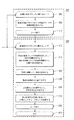
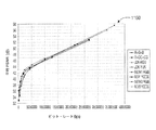
図6Aおよび図6Bに移ると、ATVイントラ・オンリーの場合の平均PSNR対ビット・レートのプロットが、それぞれ参照番号600および650によって全体的に示されている。
Turning to FIGS. 6A and 6B, plots of average PSNR versus bit rate for the ATV intra only case are indicated generally by the
図7Aおよび図7Bに移ると、CTイントラ・オンリーの場合の平均PSNR対ビット・レートのプロットが、それぞれ参照番号700および750によって全体的に示されている。
Turning to FIGS. 7A and 7B, plots of average PSNR versus bit rate for the CT intra only case are indicated generally by the
図8Aおよび図8Bに移ると、DTイントラ・オンリーの場合の平均PSNR対ビット・レートのプロットが、それぞれ参照番号800および850によって全体的に示されている。
Turning to FIGS. 8A and 8B, plots of average PSNR versus bit rate for DT intra-only are indicated generally by the
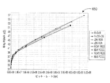
図9Aおよび図9Bに移ると、MIR_HDイントラ・オンリーの場合の平均PSNR対ビット・レートのプロットが、それぞれ参照番号900および950によって全体的に示されている。
Turning to FIGS. 9A and 9B, plots of average PSNR versus bit rate for the MIR_HD intra only case are indicated generally by the
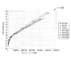
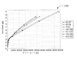
図10Aおよび図10Bに移ると、RTイントラ・オンリーの場合の平均PSNR対ビット・レートのプロットが、それぞれ参照番号1000および1050によって全体的に示されている。
Turning to FIGS. 10A and 10B, plots of average PSNR versus bit rate for RT intra only are indicated generally by the
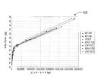
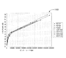
図11Aおよび図11Bに移ると、STB_HDイントラ・オンリーの場合の平均PSNR対ビット・レートのプロットが、それぞれ参照番号1100および1150によって全体的に示されている。
Turning to FIGS. 11A and 11B, plots of average PSNR versus bit rate for STB_HD intra-only are indicated generally by the
具体的には、図6A、図7A、図8A、図9A、図10A、および図11Aは、(「新しい(NEW)」という語によって示され、この語が前に置かれる)提案するアドバンスト4:4:4プロファイル対それに対応する近似結果についての試験結果を示す。さらに、図6B、図7B、図8B、図9B、図10B、および図11Bは、(「新しい」という語によって示され、この語が前に置かれる)提案するアドバンスト4:4:4プロファイル対JPEG2000についての試験結果を示す。 Specifically, FIG. 6A, FIG. 7A, FIG. 8A, FIG. 9A, FIG. 10A, and FIG. 11A are proposed Advanced 4 (indicated by the word “NEW” and preceded by this word). : Shows test results for 4: 4 profiles versus corresponding approximation results. Further, FIG. 6B, FIG. 7B, FIG. 8B, FIG. 9B, FIG. 10B, and FIG. 11B show the proposed advanced 4: 4: 4 profile pair (indicated by the word “new” and preceded by the word). The test result about JPEG2000 is shown.
図6A、図6Bから図11A、図11Bのすべてにおいて、PSNRはデシベル(dB)で表され、ビット・レートはビット毎秒(bps)で表される。ATV、CT、DT、MIR、RT、STBは、試験チップの名前である。 In all of FIGS. 6A, 6B to 11A, 11B, PSNR is expressed in decibels (dB) and bit rate is expressed in bits per second (bps). ATV, CT, DT, MIR, RT, STB are names of test chips.
JVT−J042、Film−Originated Test Sequencesに記載されているすべてのJVT/FRExt試験系列が、試験で使用された。それらはすべて、4:4:4 10ビットのフィルム材料(film material)であり、各クリップは58のフレームを有する。 All JVT / FRExt test series described in JVT-J042, Film-Originated Test Sequences were used in the study. They are all 4: 4: 4 10-bit film material and each clip has 58 frames.
提案するアドバンスト4:4:4プロファイルは、JVT参照ソフトウェアJM9.6で実施された。イントラ・オンリーおよびIBBP符号化構造の両方が、試験で使用された。量子化パラメータは、R−D曲線の各々について、6、12、18、24、30、および42に設定された。RD最適化モード選択が使用された。 The proposed Advanced 4: 4: 4 profile was implemented with JVT reference software JM9.6. Both intra-only and IBBP coding structures were used in the tests. The quantization parameter was set to 6, 12, 18, 24, 30, and 42 for each of the RD curves. RD optimization mode selection was used.
提案するアドバンスト4:4:4プロファイルは、すべての個別入力成分上でYUVFormat=0(4:0:0)とした参照ソフトウェアを実行することによって達成された結果とも比較された。圧縮ビット・レートを計算するための総圧縮ビットを得るために、3つの別々の個別圧縮ビット・カウントが単純に足し合わされた。 The proposed Advanced 4: 4: 4 profile was also compared with the results achieved by running the reference software with YUVFormat = 0 (4: 0: 0) on all individual input components. To obtain the total compressed bits for calculating the compressed bit rate, three separate individual compressed bit counts were simply added.
JPEG2kに関して、KaKadu V2.2.3ソフトウェアが、試験で使用された。試験結果は、9/7タップ双直交ウェーブレット・フィルタを用いる5レベルのウェーブレット分解を使用することによって生成された。フレーム当たり唯一のタイルが存在し、与えられた目標レートについてのRD最適化も使用された。 For JPEG2k, KaKadu V2.2.3 software was used in the tests. Test results were generated by using a 5 level wavelet decomposition with a 9/7 tap biorthogonal wavelet filter. There was only one tile per frame and RD optimization was also used for a given target rate.
PSNR測定のすべてが、RGB領域で実行された。全体的な圧縮品質を比較するために、(PSNR(赤)+PSNR(緑)+PSNR(青))/3として定義される平均PSNRが使用された。これは主に、JPEG2k圧縮データが、ソフトウェアによって提供される未知のレート制御アルゴリズムを使用して計算されるためである。いくつかの場合、特にJPEG2k色変換が使用された場合、RGB PSNR値は、互いに非常に大きく離れている。 All PSNR measurements were performed in the RGB region. In order to compare the overall compression quality, an average PSNR defined as (PSNR (red) + PSNR (green) + PSNR (blue)) / 3 was used. This is mainly because JPEG2k compressed data is calculated using an unknown rate control algorithm provided by the software. In some cases, particularly when JPEG 2k color conversion is used, the RGB PSNR values are very far away from each other.
圧縮比較は、以下のように実行された。
・New1:単一の予測モードを用いる提案するアドバンスト4:4:4プロファイル。
・New3:3つの予測モードを用いる提案するアドバンスト4:4:4プロファイル。
・RCT−OFF:RCT=offとしたRGB入力。
・RCT−ON:RCT=onとしたRGB入力。
・YCOCG:RGBからYCOCGへの変換が符号復号器の外で実行された。その後、変換YCOCGが、JVTソフトウェアへの入力として使用された。
・R+G+B:R、G、およびB信号を別々に圧縮することによって近似された提案する方法。
・Y+CO+CG:変換Y、CO、およびCG信号を別々に圧縮することによって近似された提案する方法。
・J2k_RGB:JPEG2k圧縮がRGB領域で実行された。JPEG2k色変換はオフにされた。
・J2k_YUV:JPEG2k圧縮がYUV領域で実行された。JPEG2k色変換が使用された。
The compression comparison was performed as follows.
New 1: Proposed advanced 4: 4: 4 profile using a single prediction mode.
New 3: Proposed advanced 4: 4: 4 profile using 3 prediction modes.
RCT-OFF: RGB input with RCT = off.
RCT-ON: RGB input with RCT = on.
YCOCG: RGB to YCOCG conversion was performed outside the code decoder. The transformed YCOCG was then used as input to the JVT software.
R + G + B: the proposed method approximated by compressing the R, G, and B signals separately.
Y + CO + CG: A proposed method approximated by compressing the transformed Y, CO, and CG signals separately.
J2k_RGB: JPEG2k compression was performed in the RGB region. JPEG 2k color conversion was turned off.
J2k_YUV: JPEG2k compression was performed in the YUV region. JPEG 2k color conversion was used.
試験結果によれば、一実施形態において構成される本発明の原理に従った実施は、一般に、全体的な圧縮効率に関して、JPEG2kと非常に類似している。いくつかの場合では、僅かながらもより優れている。 According to test results, implementation according to the principles of the present invention configured in one embodiment is generally very similar to JPEG2k in terms of overall compression efficiency. In some cases it is slightly better.
さらに、一実施形態において構成される本発明の原理に従った実施は、40dB(PSNR)を超える品質について現行のハイ4:4:4プロファイルよりも非常に優れた性能(圧縮)を提供する。具体的には、New1−YCOCGまたはNew3−YCOCGは、YCOCGおよびRCT−ONよりも優れており、New1−RGBまたはNew3−RGBは、RCT−OFFよりも優れている。45dB(PSNR)以上のPSNRでは、平均PSNRにおける平均的な改善は、1.5dBよりも大きい。最後の例では、45dBに等しいPSNRにおいて、改善は25%より大きいビット節約に変換され得る。 Furthermore, implementation in accordance with the principles of the present invention configured in one embodiment provides much better performance (compression) than current high 4: 4: 4 profiles for quality above 40 dB (PSNR). Specifically, New1-YCOCG or New3-YCOCG is superior to YCOCG and RCT-ON, and New1-RGB or New3-RGB is superior to RCT-OFF. For PSNR above 45 dB (PSNR), the average improvement in average PSNR is greater than 1.5 dB. In the last example, at a PSNR equal to 45 dB, the improvement can be converted to a bit saving greater than 25%.
試験結果によれば、色変換は、TP、RTなど、内容がより大きく色飽和(color saturated)している場合に、符号化性能を助けると思われる。すなわち、色が無彩であまり飽和していない場合、RGB領域における符号化が、正しい選択であるかもしれない。上の観察は、どの色変換が使用されるかとは無関係である。 According to the test results, color conversion seems to help the coding performance when the content is more color saturated, such as TP, RT. That is, if the color is achromatic and not very saturated, encoding in the RGB region may be the right choice. The above observation is independent of which color transformation is used.
New1−YCOCGまたはNew3−YCOCGとJPEG−2k_YUVの結果を比較すると、符号化効率の改善に関する特定の色変換の性能が、非常に内容依存であることが観察された。常に最善である単一の色変換は存在しない。従って、発明者らのデータは、符号化(または復号化)ループの内側にRCTなどの色変換をもつことが良いアイデアでないことがあることを確認した。代わりに、必要であれば、符号器/復号器の外側で色変換を実行することは、全体的な圧縮システムに、より優れ且つより堅牢な性能を提供させることができる。 When comparing the results of New1-YCOCG or New3-YCOCG and JPEG-2k_YUV, it was observed that the performance of a particular color conversion with respect to improved coding efficiency was very content dependent. There is no single color transformation that is always the best. Therefore, the inventors' data has confirmed that it may not be a good idea to have a color transform such as RCT inside the encoding (or decoding) loop. Instead, performing color conversion outside the encoder / decoder, if necessary, can allow the overall compression system to provide better and more robust performance.
YCOCGをRCT−ONと比較すると、試験結果は、RCTからの符号化効率の改善を示していない。加えて、RCTがオンにされた参照ソフトウェアを実行することは、符号化時間を著しく増大させることに留意されたい。実行時間は、2.5倍よりも長くなった。 When comparing YCOCG with RCT-ON, the test results do not show improved coding efficiency from RCT. In addition, it should be noted that running reference software with RCT turned on significantly increases the encoding time. The execution time was longer than 2.5 times.
一実施形態において構成される本発明の原理によるシンタックスおよびセマンティクス変更に関して、次に説明する。 The following describes the syntax and semantic changes according to the principles of the present invention configured in one embodiment.
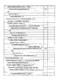
図12に移ると、H.264シーケンス・パラメータ・シンタックスについての表が、参照番号1200によって全体的に示されている。一実施形態において構成される本発明の原理によるシンタックスへの変更は、イタリック体テキストによって示されている。
Turning to FIG. A table for H.264 sequence parameter syntax is indicated generally by the
図13に移ると、H.264残差データ・シンタックスについての表が、参照番号1300によって全体的に示されている。一実施形態において構成される本発明の原理によるシンタックスへの追加/変更は、イタリック体テキストによって示されている。表1300では、luma1およびluma2をそれぞれサポートするために、残差データ・ヘッダ内の輝度セクションは、必要なテキスト修正を伴って、2回繰り返される。 Turning to FIG. A table for the H.264 residual data syntax is indicated generally by the reference numeral 1300. Additions / changes to the syntax according to the principles of the present invention configured in one embodiment are indicated by italic text. In table 1300, to support luma1 and luma2, respectively, the luminance section in the residual data header is repeated twice with the necessary text modifications.
上述したように、上で説明した第1の組合せ実施形態は、JVT参照ソフトウェアJM9.6で本発明の原理を実施することによって、評価および試験された。New1−RGBまたはNew1−YCOCGによってマークされた試験結果は、第1の組合せ実施形態を表す。 As described above, the first combination embodiment described above has been evaluated and tested by implementing the principles of the present invention with JVT reference software JM9.6. Test results marked by New1-RGB or New1-YCOCG represent the first combination embodiment.
上述したように、一実施形態において構成される本発明の原理によれば、単一の空間予測モードの代わりに、3つの制限された空間予測器からなる組(またはその一部)が、成分チャネル(例えば、RGB、YUV、YCrCbフォーマットなど)に対して利用される。さらに、上述したように、この実施形態は、例えば、内容の3つの成分チャネルすべてを符号化するために輝度符号化アルゴリズムだけを使用すること、および/または前処理ステップとして色変換を使用することなど、本明細書で説明するその他の実施形態と組み合わされてもよい。 As described above, according to the principles of the present invention configured in one embodiment, instead of a single spatial prediction mode, a set (or part thereof) of three limited spatial predictors is a component. Used for channels (eg, RGB, YUV, YCrCb formats, etc.). Furthermore, as described above, this embodiment uses, for example, only a luminance encoding algorithm to encode all three component channels of content, and / or uses color conversion as a pre-processing step. Etc., and may be combined with other embodiments described herein.
色成分に対して3つの制限された空間予測器からなる組(またはその一部)を使用すること、3つの色成分のすべてを符号化するために輝度符号化アルゴリズムだけを使用すること、および前処理ステップとして色変換を使用する(すなわち、圧縮ループ内にRCTをもたない)ことを含む、上で説明した第2の組合せ実施形態に関して、次に説明する。この実施形態のいくつかの変形も一緒に説明する。 Using a set of (or part of) three limited spatial predictors for color components, using only a luminance encoding algorithm to encode all three color components, and The second combination embodiment described above, including using color transformation as a pre-processing step (ie, having no RCT in the compression loop) will now be described. Several variations of this embodiment are also described.
図14に移ると、例示的なビデオ符号化プロセスと、それに付随する符号化前色変換ステップが、それぞれ参照番号1400および1401によって全体的に示されている。
Turning to FIG. 14, an exemplary video encoding process and the accompanying pre-encoding color conversion steps are indicated generally by
符号化前色変換ブロック1401が、ブロック1406、1408、1410を含むことを理解されたい。さらに、符号化前色変換ブロック1401は、任意選択であること、従って、本発明のいくつかの実施形態では省略できることも理解されたい。
It should be understood that the pre-encoding
符号化前色変換ブロック1401は、画像内の各ブロックに関するループを開始し、制御を機能ブロック1408に渡す、ループ端ブロック1406を含む。機能ブロック1408は、現在の画像ブロックのビデオ信号データの色前処理を実行し、制御をループ端ブロック1410に渡す。ループ端ブロック1410は、ループを終了する。さらに、ループ端ブロック1410は、ビデオ符号化プロセス1400に含まれるループ端ブロック1412に制御を渡す。
Pre-encoding
ループ端ブロック1412は、画像内の各ブロックに関するループを開始し、制御を機能ブロック1415に渡す。機能ブロック1415は、現在の画像ブロックの各色成分に対して共通の予測器を使用して、現在の画像ブロックの動き補償または空間予測を形成し、制御を機能ブロック1420に渡す。機能ブロック1420は、現在の画像ブロックから動き補償または空間予測を減算して、予測残差を形成し、制御を機能ブロック1430に渡す。機能ブロック1430は、予測残差を変換および量子化し、制御を機能ブロック1435に渡す。機能ブロック1435は、予測残差を逆変換および量子化して、符号化予測残差を形成し、制御を機能ブロック1445に渡す。機能ブロック1445は、符号化残差を予測に追加して、符号化ピクチャ・ブロックを形成し、制御をループ終了ブロック1450に渡す。ループ終了ブロック1450は、ループを終了し、制御を終了ブロック1455に渡す。
図15に移ると、例示的なビデオ復号化プロセスと、それに付随する復号化後逆色変換ステップが、それぞれ参照番号1500および1560によって全体的に示されている。
Turning to FIG. 15, an exemplary video decoding process and the accompanying post-decoding inverse color transformation steps are indicated generally by
復号化後逆色変換ブロック1560が、ブロック1562、1564、1566、1568を含むことを理解されたい。さらに、復号化後逆色変換ブロック1560は、任意選択であること、従って、本発明のいくつかの実施形態では省略できることも理解されたい。
It should be understood that the post-decoding inverse
復号化プロセス1500は、画像内の現在のブロックに関するループを開始し、制御を機能ブロック1515に渡す、ループ端ブロック1510を含む。機能ブロック1515は、符号化残差をエントロピー復号化し、制御を機能ブロック1520に渡す。機能ブロック1520は、復号化残差を逆変換および量子化して、符号化残差を形成し、制御を機能ブロック1530に渡す。機能ブロック1530は、符号化残差を、各色成分に対して共通の予測器から形成された予測に追加して、符号化ピクチャ・ブロックを形成し、制御をループ端ブロック1535に渡す。ループ端ブロック1535は、ループを終了し、制御を終了ブロック1540に渡す。
The
いくつかの実施形態では、ループ端ブロック1535は任意選択で、復号化後逆色変換ブロック1560に、詳細には、復号化後逆色変換ブロック1560に含まれるループ端ブロック1562に制御を渡す。ループ端ブロック1562は、画像内の各ブロックに関するループを開始し、制御を機能ブロック1564に渡す。機能ブロック1564は、現在の画像ブロックのビデオ信号データの逆色後処理を実行し、制御をループ端ブロック1566に渡す。ループ端ブロック1566は、ループを終了し、制御を終了ブロック1568に渡す。
In some embodiments, the
上述したように、アドバンスト4:4:4プロファイル用の新しいプロファイル(profile_idc=166)が開示される。この新しいプロファイルは、第2の組合せ実施形態について以下本明細書で説明する対応するセマンティックおよびシンタックス変更を施して、第2の組合せ実施形態のために使用することもできる。この新しいprofile_idcは、シーケンス・パラメータ・セット内に追加され、入力フォーマットが4:4:4であり、3つの入力チャネルすべてが輝度として同じように符号化されることを示すために、後続ヘッダ内で主に使用される。 As described above, a new profile (profile_idc = 166) for the Advanced 4: 4: 4 profile is disclosed. This new profile can also be used for the second combined embodiment, with corresponding semantic and syntax changes described below for the second combined embodiment. This new profile_idc was added in the sequence parameter set, in the subsequent header to indicate that the input format is 4: 4: 4 and all three input channels are encoded the same as luminance. Mainly used in.
H.264規格に対する必要な変更を最小限に抑えるため、アドバンスト4:4:4プロファイル用の新しいマクロブロック・タイプは開示されない。代わりに、H.264規格のTable 7−11、Table 7−13、およびTable 7−14に列挙された、関連する符号化パラメータを伴うマクロブロック・タイプのすべては、依然として有効である。イントラ・マクロブロックの場合、輝度、Cr、およびCbの3つの入力チャネルのすべてが、H.264規格のTable 7−11で定義されるMbPartPredModeに基づいて符号化される。例えば、アドバンスト4:4:4プロファイルにおけるIntra_4×4マクロブロックは、すべての入力成分チャネルが、H.264規格のTable 8−2で与えられる9個の可能な予測モードのすべてを使用することによって符号化できることを意味する。参考として、現行のハイ4:4:4プロファイルでは、Intra_4×4マクロブロック用のチャネルのうちの2つが、色度として扱われ、H.264規格のTable 8−5内の4個の可能なイントラ予測モードのうちの1つだけが使用される。BおよびPマクロブロックの場合、アドバンスト4:4:4プロファイルのために施される変更は、分数ピクセル位置にある参照ピクセル値の計算のための補間プロセスにおいて発生する。ここでは、H.264規格のセクション8.4.2.2.1に記載された手続きである、輝度サンプル補間プロセス(Luma sample interpolation process)が、輝度、Cr、およびCbに適用される。再び参考として、現行のハイ4:4:4プロファイルは、入力チャネルのうちの2つに対して、H.264規格のセクション8.4.2.2.2の色度サンプル補間プロセス(Chroma sample interpolation process)を使用する。 H. In order to minimize the necessary changes to the H.264 standard, a new macroblock type for the Advanced 4: 4: 4 profile is not disclosed. Instead, H.C. All of the macroblock types with associated coding parameters listed in Table 7-11, Table 7-13, and Table 7-14 of the H.264 standard are still valid. For intra macroblocks, all three input channels of luminance, Cr, and Cb are H.264. It is encoded based on MbPartPredMode defined in Table 7-11 of the H.264 standard. For example, an Intra — 4 × 4 macroblock in the advanced 4: 4: 4 profile has all input component channels as H.264. It means that it can be encoded by using all 9 possible prediction modes given in Table 8-2 of the H.264 standard. For reference, in the current high 4: 4: 4 profile, two of the channels for Intra — 4 × 4 macroblock are treated as chromaticity. Only one of the four possible intra prediction modes in the H.264 standard Table 8-5 is used. For B and P macroblocks, the changes made for the advanced 4: 4: 4 profile occur in the interpolation process for the calculation of reference pixel values at fractional pixel locations. Here, H. The luminance sample interpolation process, the procedure described in section 8.4.2.2.1 of the H.264 standard, is applied to luminance, Cr, and Cb. Again, for reference, the current high 4: 4: 4 profile is H.264 for two of the input channels. The Chroma sample interpolation process of section 8.4.2.2.2.2 of the H.264 standard is used.
CABACがエントロピー符号化モードとして選択された場合、輝度用に現在定義されているのと同じコンテキスト・モデルの2つの別個の組が、CrおよびCb用に生成される。それらも、符号化の最中に独立に更新される。 If CABAC is selected as the entropy coding mode, two separate sets of the same context model currently defined for luminance are generated for Cr and Cb. They are also updated independently during encoding.
最後に、前記実施形態では、符号化ループ内にRCTブロックが存在しないので、ResidueColorTransformFlagは、アドバンスト4:4:4プロファイルのシーケンス・パラメータ・セットから取り除かれる。 Finally, in the above embodiment, since there is no RCT block in the encoding loop, ResidueColorTransformFlag is removed from the Advanced 4: 4: 4 profile sequence parameter set.
この時点まで、大部分のシンタックス変更は、図13に示される残差データにおいて発生し、提案するアドバンスト4:4:4プロファイルにおいてCrおよびCbをサポートするために、輝度用の元のシンタックスが2度繰り返される。 Up to this point, most syntax changes occur in the residual data shown in FIG. 13, and the original syntax for luminance is used to support Cr and Cb in the proposed Advanced 4: 4: 4 profile. Is repeated twice.
H.264マクロブロック・レイヤ表(図示せず)に関して、対応するシンタックスに対するセマンティック変更は以下を含む。 H. For a H.264 macroblock layer table (not shown), semantic changes to the corresponding syntax include:
coded_block_pattern(追加)。chroma_format_idcが3に等しく、且つcoded_block_patternが存在する場合、CodedBlockPatternChromaは0に設定される。加えて、CodedBlockPatternLumaは、マクロブロックの12個の8×8輝度、Cb、およびCrブロックの各々について、以下のケースの一方、すなわち、(1)8×8輝度ブロック、8×8Cbブロック、および8×8Crブロック内の12個の4×4輝度ブロックのすべての変換係数レベルが0に等しいケース、(2)8×8輝度ブロック、8×8Cbブロック、および8×8Crブロック内の1つまたは複数の4×4輝度ブロックの1つまたは複数の変換係数レベルが非0の値をもつケースの一方を指定する。 coded_block_pattern (added). If chroma_format_idc is equal to 3 and coded_block_pattern is present, CodedBlockPatternChroma is set to 0. In addition, CodedBlockPatternLuma for each of the 12 8 × 8 luminance, Cb, and Cr blocks of the macroblock is one of the following cases: (1) 8 × 8 luminance block, 8 × 8 Cb block, and 8 The case where all the transform coefficient levels of 12 4 × 4 luminance blocks in a × 8Cr block are equal to 0, (2) one or more of 8 × 8 luminance block, 8 × 8Cb block, and 8 × 8Cr block One of the cases where one or more transform coefficient levels of the 4 × 4 luminance block have a non-zero value.
第2の組合せ実施形態(または3つの制限された空間予測器からなる組(またはその一部)の使用に関する単独の実施形態)によるイントラ・ブロックのための空間予測モード選択に関して、次に説明する。 With respect to spatial prediction mode selection for intra blocks according to the second combined embodiment (or a single embodiment relating to the use of (or part of) a set of three limited spatial predictors), the following is described. .
各入力チャネルを別々に符号化する場合のように、各成分が、その最良のMbPartPredModeと、後続の最良の空間予測モードを独立に選択するため、いくつかの新しいイントラ・ブロック・タイプが、H.264規格のTable 7−11に追加されてよい。その結果、H.264規格に対する大きな変更が行われる。第2の組合せ実施形態に関係する一実施形態では、現行のmb_typesは無変更のままであり、代替策が提供される。前記実施形態では、3つの入力チャネルは、同じMbPartPredModeまたはマクロブロック・タイプを用いて符号化されるように制限される。その後、3つの別個の予測モードをサポートするために、僅かな新しい要素が、マクロブロック予測シンタックスに追加される。従って、各成分チャネルに対する予測誤差を最小化するために、各成分は、理論的にはまだ、その最良の空間予測モードを独立に選択することができる。例えば、Intra_4×4マクロブロックがmb_typeとして選択されると仮定すると、輝度、Cr、およびCbは依然として、例えば、輝度にはIntra_4×4_Vertical、CrにはIntra_4_4_Horizontal、CbにはIntra_4×4_Diagonal_Down_Leftなど、H.264規格のセクション8.3.1.1のTable 8−2内に、その最良の空間予測モードを見出すことができる。 Because each component independently selects its best MbPartPredMode and subsequent best spatial prediction mode, as in the case of encoding each input channel separately, several new intra block types are . It may be added to Table 7-11 of the H.264 standard. As a result, H.C. Major changes to the H.264 standard. In one embodiment related to the second combined embodiment, the current mb_types remain unchanged and an alternative is provided. In the embodiment, the three input channels are limited to be encoded using the same MbPartPredMode or macroblock type. A few new elements are then added to the macroblock prediction syntax to support three separate prediction modes. Thus, in order to minimize the prediction error for each component channel, each component can still independently select its best spatial prediction mode. For example, assuming an Intra_4 × 4 macroblock is selected as mb_type, luminance, Cr, and Cb are still, for example, Intra_4 × 4_Vertical for luminance, Intra_4_4_Horizontal for Cr, Intra_4 × 4_Diagonal_Down. The best spatial prediction mode can be found in Table 8-2 of section 8.3.1.1 of the H.264 standard.
上で説明した第1の組合せ実施形態に関係する別のアプローチは、3つの入力チャネルすべてを、同じ予測モードを共用するように制約するものである。これは、マクロブロック予測シンタックス内の、prev_intra4×4_pre_mode_flag、rem_intra4×4_pred_mode、pre_intra8×8_pred_mode_flag、およびrem_intra8×8_pred_modeなど、既存のシンタックス要素によって現在は保持される、予測情報を使用することによって行うことができる。このオプションは、H.264規格に対するより僅かな変更と、さらに符号化効率の僅かな低下ももたらす。 Another approach related to the first combination embodiment described above is to constrain all three input channels to share the same prediction mode. This is because, in the macroblock prediction syntax, prev_intra4 × 4_pre_mode_flag, rem_intra4 × 4_pred_mode, pre_intra8 × 8_pred_mode_flag, and the existing syntax that is used by the information that is predicted by the existing syntax such as the information that is used by the rem_intra8 × 8_pred_mode, and the rem_intra8 × 8_pred_mode Can do. This option is There is also a slight change to the H.264 standard and a slight decrease in coding efficiency.
試験結果に基づいて、3つの予測モードの使用は、第1の組合せ実施形態よりも約0.2dBだけ全体的な符号化性能を向上させることができる。 Based on the test results, the use of the three prediction modes can improve the overall coding performance by about 0.2 dB over the first combined embodiment.
図16に移ると、H.264マクロブロック予測シンタックスについての表が、参照番号1600によって全体的に示されている。参考として、3つの予測モードの使用をサポートする修正マクロブロック予測シンタックスを以下に列挙する。
輝度用にprev_intra4×4_pred_mode_flag0およびrem_intra4×4_pred_mode0。
Cr用にprev_intra4×4_pred_mode_flag1およびrem_intra4×4_pred_mode1。
Cb用にprev_intra4×4_pred_mode_flag2およびrem_intra4×4_pred_mode2。
Turning to FIG. A table for the H.264 macroblock prediction syntax is indicated generally by the
Prev_intra4 × 4_pred_mode_flag0 and rem_intra4 × 4_pred_mode0 for luminance.
Prev_intra4 × 4_pred_mode_flag1 and rem_intra4 × 4_pred_mode1 for Cr.
Prev_intra4 × 4_pred_mode_flag2 and rem_intra4 × 4_pred_mode2 for Cb.
第2の組合せ実施形態についての、一実施形態において構成される本発明の原理に従って実行されたシミュレーション結果に関して、次に説明する。 The simulation results performed in accordance with the principles of the present invention configured in one embodiment for the second combination embodiment will now be described.
JVT−J042、Film−Originated Test Sequences、JVT J039(Viper)に記載されているすべてのJVT/FRExt試験系列。それらはすべて、4:4:4 10ビットの材料であり、各クリップは58のフレームを有する。 All JVT / FRExt test series described in JVT-J042, Film-Originated Test Sequences, JVT J039 (Viper). They are all 4: 4: 4 10-bit material and each clip has 58 frames.
提案するアルゴリズムは、JVT参照ソフトウェアJM9.6で実施され、修正ソフトウェアが試験で使用された。イントラ・オンリーおよびIBRrBPの両方が試験された。ここで、「Br」は、記録Bピクチャを意味する。イントラ・オンリーのケースは、量子化パラメータが6、12、18、24、30、36、および42に等しいすべてのシーケンスについて行われた。シミュレーションには多くの時間が必要とされるため、量子化パラメータが12、18、24、30、および36に等しいフィルム・クリップについては、IBRrBP GOP構造だけが行われた。4:4:4 AHGの説明に従って、以下のキー・パラメータが試験で使用された。
SymbolMode=1
RDOptimization=1
ScalingMatrixPresentFlag=0
OffsetMatrixPresentFlag=1
QoffsetMatrixFile=“q_offset.cfg”
AdaptiveRounding=1
AdaptRndPeriod=1
AdaptRndChroma=1
AdaptRndWFactorX=8
SearchRange=64
UseFME=1
The proposed algorithm was implemented with JVT reference software JM9.6, and modified software was used in the tests. Both intra-only and IBRrBP were tested. Here, “Br” means a recorded B picture. The intra-only case was performed for all sequences where the quantization parameter was equal to 6, 12, 18, 24, 30, 36, and 42. Since the simulation takes a lot of time, only IBRrBP GOP structures were performed for film clips with quantization parameters equal to 12, 18, 24, 30, and 36. The following key parameters were used in the test according to the 4: 4: 4 AHG description.
SymbolMode = 1
RDoptimization = 1
ScalingMatrixPresentFlag = 0
OffsetMatrixPresentFlag = 1
QoffsetMatrixFile = “q_offset.cfg”
AdaptiveRounding = 1
AdaptRndPeriod = 1
AdaptRndChroma = 1
AdaptRndWFFactorX = 8
SearchRange = 64
UseFME = 1
JPEG2kに関して、KaKadu V2.2.3ソフトウェアが、試験で使用された。試験結果は、9/7タップ双直交ウェーブレット・フィルタを用いる5レベルのウェーブレット分解を使用することによって生成された。フレーム当たり唯一のタイルが存在し、与えられた目標レートについてのRD最適化も使用された。 For JPEG2k, KaKadu V2.2.3 software was used in the tests. Test results were generated by using a 5-level wavelet decomposition with a 9/7 tap bi-orthogonal wavelet filter. There was only one tile per frame and RD optimization was also used for a given target rate.
PSNR測定は主に、上で説明したクリップの場合はRGBである、原内容の元の色領域で計算された。全体的な圧縮品質を比較するために、(PSNR(赤)+PSNR(緑)+PSNR(青))/3として定義される平均PSNRが使用された。 PSNR measurements were calculated primarily in the original color region of the original content, which is RGB in the case of the clip described above. In order to compare the overall compression quality, an average PSNR defined as (PSNR (red) + PSNR (green) + PSNR (blue)) / 3 was used.
圧縮比較は、以下のように実行された。
New1:単一の予測モードを用いる提案するアドバンスト4:4:4プロファイル。
New3:3つの予測モードを用いる提案するアドバンスト4:4:4プロファイル。
RCT−OFF:RCT=offとしたRGB入力。
RCT−ON:RCT=onとしたRGB入力。
YCOCG:RGBからYCOCGへの変換が符号復号器の外で実行された。その後、変換YCOCGが、JVTソフトウェアへの入力として使用された。
R+G+B:R、G、およびB信号を別々に圧縮することによって近似された提案する方法。
Y+CO+CG:変換Y、CO、およびCG信号を別々に圧縮することによって近似された提案する方法。
JPEG2k_RGB:JPEG2k圧縮がRGB領域で実行された。JPEG2k色変換はオフにされた。
JPEG2k_YUV:JPEG2k圧縮がYUV領域で実行された。JPEG2k色変換が使用された。
The compression comparison was performed as follows.
New1: Proposed advanced 4: 4: 4 profile using a single prediction mode.
New 3: Proposed advanced 4: 4: 4 profile using 3 prediction modes.
RCT-OFF: RGB input with RCT = off.
RCT-ON: RGB input with RCT = on.
YCOCG: RGB to YCOCG conversion was performed outside the code decoder. The transformed YCOCG was then used as input to the JVT software.
R + G + B: A proposed method approximated by compressing R, G, and B signals separately.
Y + CO + CG: A proposed method approximated by compressing the transformed Y, CO, and CG signals separately.
JPEG2k_RGB: JPEG2k compression was performed in the RGB region. JPEG 2k color conversion was turned off.
JPEG2k_YUV: JPEG2k compression was performed in the YUV region. JPEG 2k color conversion was used.
イントラ・オンリーのケースの場合、本発明の原理による提案するアドバンスト4:4:4プロファイルは、全体的な圧縮効率に関して、JPEG2kと非常に類似している。いくつかの場合では、僅かながらもより優れている。 For the intra-only case, the proposed Advanced 4: 4: 4 profile according to the principles of the present invention is very similar to JPEG2k in terms of overall compression efficiency. In some cases it is slightly better.
本発明の原理によるアプローチは明らかに、現行のハイ4:4:4プロファイルよりも優れている。45dB(PSNR)以上のPSNRでは、平均PSNRにおける平均的な改善は、1.5dBよりも大きい。いくつかのケースでは、45dBに等しいPSNRにおいて、改善は25%より大きいビット節約に変換され得る。 The approach according to the principles of the present invention is clearly superior to the current high 4: 4: 4 profile. For PSNR above 45 dB (PSNR), the average improvement in average PSNR is greater than 1.5 dB. In some cases, at a PSNR equal to 45 dB, the improvement can be converted to a bit saving greater than 25%.
同じブロック・タイプを用いたとしても、3つの予測モードの使用は、単一モードよりも僅かに優れている。しかし、より多くのシンタックスおよびセマンティック変更が、利用されることがある。 Even with the same block type, the use of the three prediction modes is slightly better than the single mode. However, more syntax and semantic changes may be utilized.
本発明の実施形態の原理によって提供される多くの関連する利点/特徴のうちのいくつかに関して、次に説明する。 Some of the many related advantages / features provided by the principles of embodiments of the present invention will now be described.
試験結果は、本発明の原理に対応する改善を利用する提案するアドバンスト4:4:4プロファイルが、現行のハイ4:4:4プロファイルと比較した場合に、改善された性能を達成することを示している。性能増加は著しい。加えて、色変換を符号復号器の外に移動することは、符号復号器の構成をすべての色フォーマット間で一貫したものにする。その結果、それは実施をより容易にし、コストを低減する。それはまた、より良い符号化効率を達成するための最適化色変換に関して、符号復号器をより堅牢にもする。また、提案するアプローチは、新しい符号化ツールを追加せず、シンタックスおよびセマンティクスに対するいくつかの僅かな変化を必要とするだけである。 Test results show that the proposed Advanced 4: 4: 4 profile, which utilizes improvements corresponding to the principles of the present invention, achieves improved performance when compared to the current high 4: 4: 4 profile. Show. The performance increase is significant. In addition, moving the color transformation out of the code decoder makes the code decoder configuration consistent across all color formats. As a result, it makes implementation easier and reduces costs. It also makes the code decoder more robust with respect to optimized color transforms to achieve better coding efficiency. Also, the proposed approach does not add new coding tools and only requires some slight changes to the syntax and semantics.
従って、一実施形態において構成される本発明の原理によれば、ビデオ符号化および復号化のための方法および装置が提供される。現在達成可能な性能を超えて性能を改善する、既存のH.264規格に対する変更が提供される。さらに、性能は、高品質アプリケーション用のJPEG−2000さえも超えて改善される。一実施形態において構成される本発明の原理によれば、H.264規格における4:4:4符号化性能の著しい改善は、輝度符号化アルゴリズムを使用して、4:4:4コンテンツの3つの色成分のすべてを符号化することによって、達成することができる。すなわち、輝度(または使用されない色度)圧縮アルゴリズム用の新しいツールは必要ない。代わりに、既存の輝度符号化ツールが利用される。さらに、現行の4:4:4プロファイルに対するシンタックスおよびセマンティック変更は、3つの成分チャネルすべての輝度符号化をサポートするように、本発明の原理に従って実施され得る。本発明の一実施形態に従って行われた試験では、原内容が多くの空間テクスチャおよびエッジを有する場合、輝度で使用される空間予測ツールは明らかに、色度で使用されるツールよりも優れた性能を示した。試験系列のいくつかについては、すべての色成分が輝度として符号化されたとき、45db(平均PSNR)以上の圧縮品質において、30%を超えるビット削減が観察された。 Thus, according to the principles of the present invention configured in one embodiment, a method and apparatus for video encoding and decoding is provided. Improve performance beyond what is currently achievable, and improve existing H.264 performance. Changes to the H.264 standard are provided. In addition, performance is improved over even JPEG-2000 for high quality applications. In accordance with the principles of the present invention configured in one embodiment, H.264. A significant improvement in 4: 4: 4 encoding performance in the H.264 standard can be achieved by encoding all three color components of 4: 4: 4 content using a luminance encoding algorithm. . That is, there is no need for a new tool for luminance (or unused chromaticity) compression algorithms. Instead, existing luminance encoding tools are used. Furthermore, syntax and semantic changes to the current 4: 4: 4 profile can be implemented in accordance with the principles of the present invention to support luminance encoding of all three component channels. In tests performed in accordance with an embodiment of the present invention, spatial prediction tools used in luminance clearly outperform tools used in chromaticity when the original content has many spatial textures and edges. showed that. For some of the test series, a bit reduction of over 30% was observed at compression quality of 45 db (average PSNR) and above when all color components were encoded as luminance.
本明細書では、本発明は主に、H.264規格の4:4:4フォーマットを使用してサンプリングされるビデオ信号データに関して説明したが、本発明は、H.264規格のその他のフォーマット(例えば、4:2:0フォーマットおよび/または4:2:2フォーマット)ならびにその他のビデオ圧縮規格を使用してサンプリングされるビデオ信号データに関しても容易に実施できることを理解されたい。本明細書で提供される本発明の教示に鑑みて、本発明の上記およびその他の変形も、本発明の範囲を維持しながら、当業者によって容易に実施されよう。 In the present specification, the present invention mainly relates to H.264. Although described with respect to video signal data sampled using the 4: 4: 4 format of the H.264 standard, the present invention is described in H.264. It is understood that it can be easily implemented for video signal data sampled using other formats of the H.264 standard (eg, 4: 2: 0 format and / or 4: 2: 2 format) and other video compression standards. I want. In light of the teachings of the invention provided herein, these and other variations of the invention will be readily imple- mented by those skilled in the art while maintaining the scope of the invention.
本発明の上記およびその他の特徴および利点は、本明細書の教示に基づいて、当業者によって容易に確認されよう。本発明の教示が、様々な形式のハードウェア、ソフトウェア、ファームウェア、専用プロセッサ、またはそれらの組合せで実施できることを理解されたい。 These and other features and advantages of the present invention will be readily ascertainable by one of ordinary skill in the art based on the teachings herein. It should be understood that the teachings of the present invention can be implemented in various forms of hardware, software, firmware, special purpose processors, or combinations thereof.
最も好ましくは、本発明の教示は、ハードウェアとソフトウェアの組合せとして実施される。さらに、ソフトウェアは、プログラム記憶ユニット上に有形に実施されるアプリケーション・プログラムとして実施することができる。アプリケーション・プログラムは、適切な構成からなるマシンにアップロードされ、そのマシンによって実行することができる。好ましくは、マシンは、1つまたは複数の中央処理装置(「CPU」)、ランダム・アクセス・メモリ(「RAM」)、および入力/出力(「I/O」)インタフェースなどのハードウェアを有するコンピュータ・プラットフォーム上で実施される。コンピュータ・プラットフォームは、オペレーティング・システムおよびマイクロ命令コードも含むことができる。本明細書で説明した様々なプロセスおよび機能は、CPUによって実行できるマイクロ命令コードの一部もしくはアプリケーション・プログラムの一部、またはそれらの組合せとすることができる。加えて、追加のデータ記憶ユニットおよび印刷ユニットなどの様々なその他の周辺ユニットが、コンピュータ・プラットフォームに接続されてよい。 Most preferably, the teachings of the present invention are implemented as a combination of hardware and software. Furthermore, the software can be implemented as an application program that is tangibly implemented on the program storage unit. Application programs can be uploaded to and executed by a machine of appropriate configuration. Preferably, the machine is a computer having hardware such as one or more central processing units (“CPU”), a random access memory (“RAM”), and an input / output (“I / O”) interface. • Implemented on the platform. The computer platform can also include an operating system and microinstruction code. The various processes and functions described herein can be part of microinstruction code or part of an application program that can be executed by the CPU, or a combination thereof. In addition, various other peripheral units may be connected to the computer platform such as an additional data storage unit and a printing unit.
添付の図面に示された成分システム構成要素および方法のいくつかは、好ましくはソフトウェアで実施されるので、システム構成要素とプロセス機能ブロックの間の実際の接続は、本発明がプログラムされる方式に応じて異なり得ることをさらに理解されたい。本明細書の教示に鑑みて、当業者であれば、本発明の上記および類似の実施または構成を企図することができる。 Since some of the component system components and methods shown in the accompanying drawings are preferably implemented in software, the actual connection between the system components and process function blocks is in the manner in which the present invention is programmed. It should be further understood that it may vary depending on the case. In view of the teachings herein, one of ordinary skill in the related art will be able to contemplate these and similar implementations or configurations of the present invention.
本明細書では、添付の図面を参照して、例示的な実施形態を説明したが、本発明は、それらと寸分違わぬ実施形態に限定されるものではなく、様々な変更および修正が、本発明の主旨および範囲から逸脱することなく、当業者によってそれらに実施され得ることを理解されたい。そのような変更および修正のすべては、添付の特許請求の範囲で説明する本発明の範囲内に含まれることが意図されている。 Although exemplary embodiments have been described herein with reference to the accompanying drawings, the invention is not limited to the embodiments that are not to be limited to these, and various changes and modifications may be made to the embodiments. It should be understood that those skilled in the art can implement them without departing from the spirit and scope of the invention. All such changes and modifications are intended to be included within the scope of the present invention as set forth in the appended claims.
Claims (32)
Applications Claiming Priority (3)
| Application Number | Priority Date | Filing Date | Title |
|---|---|---|---|
| US67125505P | 2005-04-13 | 2005-04-13 | |
| US70083405P | 2005-07-20 | 2005-07-20 | |
| PCT/US2006/009381 WO2006112992A1 (en) | 2005-04-13 | 2006-03-16 | Luma-chroma coding with one common or three distinct spatial predictors |
Related Child Applications (1)
| Application Number | Title | Priority Date | Filing Date |
|---|---|---|---|
| JP2013133803A Division JP2013240081A (en) | 2005-04-13 | 2013-06-26 | Methods and apparatus for video encoding and decoding |
Publications (2)
| Publication Number | Publication Date |
|---|---|
| JP2008536446A true JP2008536446A (en) | 2008-09-04 |
| JP2008536446A5 JP2008536446A5 (en) | 2009-04-09 |
Family
ID=36644425
Family Applications (19)
| Application Number | Title | Priority Date | Filing Date |
|---|---|---|---|
| JP2008506473A Pending JP2008536452A (en) | 2005-04-13 | 2006-03-16 | Method and apparatus for video encoding |
| JP2008506466A Pending JP2008536447A (en) | 2005-04-13 | 2006-03-16 | Method and apparatus for video decoding |
| JP2008506465A Pending JP2008536446A (en) | 2005-04-13 | 2006-03-16 | Method and apparatus for video encoding and decoding |
| JP2008506467A Pending JP2008536448A (en) | 2005-04-13 | 2006-03-16 | Method and apparatus for video encoding |
| JP2008506469A Pending JP2008536450A (en) | 2005-04-13 | 2006-03-16 | Method and apparatus for video decoding |
| JP2013129003A Pending JP2013214994A (en) | 2005-04-13 | 2013-06-19 | Methods and apparatus for video encoding |
| JP2013129008A Pending JP2013214996A (en) | 2005-04-13 | 2013-06-19 | Methods and apparatus for video encoding |
| JP2013129010A Pending JP2013214997A (en) | 2005-04-13 | 2013-06-19 | Methods and apparatus for video decoding |
| JP2013129005A Pending JP2013214995A (en) | 2005-04-13 | 2013-06-19 | Methods and apparatus for video decoding |
| JP2013133803A Pending JP2013240081A (en) | 2005-04-13 | 2013-06-26 | Methods and apparatus for video encoding and decoding |
| JP2014261280A Pending JP2015084577A (en) | 2005-04-13 | 2014-12-24 | Methods and apparatus for video encoding and decoding |
| JP2015002641A Pending JP2015109680A (en) | 2005-04-13 | 2015-01-08 | Methods and apparatus for video encoding |
| JP2015212434A Ceased JP2016026457A (en) | 2005-04-13 | 2015-10-29 | Methods and apparatus for video encoding |
| JP2015212435A Active JP6538521B2 (en) | 2005-04-13 | 2015-10-29 | Method and apparatus for video decoding |
| JP2015214278A Active JP6345637B2 (en) | 2005-04-13 | 2015-10-30 | Method and apparatus for video decoding |
| JP2016085299A Active JP6550010B2 (en) | 2005-04-13 | 2016-04-21 | Method and apparatus for video coding |
| JP2017170916A Active JP6382413B2 (en) | 2005-04-13 | 2017-09-06 | Method and apparatus for video decoding |
| JP2017201677A Active JP6561101B2 (en) | 2005-04-13 | 2017-10-18 | Method and apparatus for video decoding |
| JP2017243608A Ceased JP2018057036A (en) | 2005-04-13 | 2017-12-20 | Methods and apparatus for video encoding |
Family Applications Before (2)
| Application Number | Title | Priority Date | Filing Date |
|---|---|---|---|
| JP2008506473A Pending JP2008536452A (en) | 2005-04-13 | 2006-03-16 | Method and apparatus for video encoding |
| JP2008506466A Pending JP2008536447A (en) | 2005-04-13 | 2006-03-16 | Method and apparatus for video decoding |
Family Applications After (16)
| Application Number | Title | Priority Date | Filing Date |
|---|---|---|---|
| JP2008506467A Pending JP2008536448A (en) | 2005-04-13 | 2006-03-16 | Method and apparatus for video encoding |
| JP2008506469A Pending JP2008536450A (en) | 2005-04-13 | 2006-03-16 | Method and apparatus for video decoding |
| JP2013129003A Pending JP2013214994A (en) | 2005-04-13 | 2013-06-19 | Methods and apparatus for video encoding |
| JP2013129008A Pending JP2013214996A (en) | 2005-04-13 | 2013-06-19 | Methods and apparatus for video encoding |
| JP2013129010A Pending JP2013214997A (en) | 2005-04-13 | 2013-06-19 | Methods and apparatus for video decoding |
| JP2013129005A Pending JP2013214995A (en) | 2005-04-13 | 2013-06-19 | Methods and apparatus for video decoding |
| JP2013133803A Pending JP2013240081A (en) | 2005-04-13 | 2013-06-26 | Methods and apparatus for video encoding and decoding |
| JP2014261280A Pending JP2015084577A (en) | 2005-04-13 | 2014-12-24 | Methods and apparatus for video encoding and decoding |
| JP2015002641A Pending JP2015109680A (en) | 2005-04-13 | 2015-01-08 | Methods and apparatus for video encoding |
| JP2015212434A Ceased JP2016026457A (en) | 2005-04-13 | 2015-10-29 | Methods and apparatus for video encoding |
| JP2015212435A Active JP6538521B2 (en) | 2005-04-13 | 2015-10-29 | Method and apparatus for video decoding |
| JP2015214278A Active JP6345637B2 (en) | 2005-04-13 | 2015-10-30 | Method and apparatus for video decoding |
| JP2016085299A Active JP6550010B2 (en) | 2005-04-13 | 2016-04-21 | Method and apparatus for video coding |
| JP2017170916A Active JP6382413B2 (en) | 2005-04-13 | 2017-09-06 | Method and apparatus for video decoding |
| JP2017201677A Active JP6561101B2 (en) | 2005-04-13 | 2017-10-18 | Method and apparatus for video decoding |
| JP2017243608A Ceased JP2018057036A (en) | 2005-04-13 | 2017-12-20 | Methods and apparatus for video encoding |
Country Status (10)
| Country | Link |
|---|---|
| US (10) | US8724699B2 (en) |
| EP (5) | EP1872586B1 (en) |
| JP (19) | JP2008536452A (en) |
| KR (5) | KR101278324B1 (en) |
| CN (1) | CN103458243B (en) |
| BR (5) | BRPI0609124A2 (en) |
| ES (2) | ES2805105T3 (en) |
| MX (5) | MX2007012705A (en) |
| MY (6) | MY167744A (en) |
| WO (5) | WO2006112992A1 (en) |
Families Citing this family (22)
| Publication number | Priority date | Publication date | Assignee | Title |
|---|---|---|---|---|
| KR101348365B1 (en) * | 2006-08-02 | 2014-01-10 | 삼성전자주식회사 | An video encoding/decoding method and apparatus |
| US8787457B2 (en) | 2007-01-11 | 2014-07-22 | Thomson Licensing | Methods and apparatus for using syntax for the coded—block—flag syntax element and the code—block—pattern syntax element for the CAVLC 4:4:4 intra, high 4:4:4 intra, and high 4:4:4 predictive profiles in MPEG-4 AVC high level coding |
| JP2008193627A (en) * | 2007-01-12 | 2008-08-21 | Mitsubishi Electric Corp | Image encoding device, image decoding device, image encoding method, and image decoding method |
| US8145002B2 (en) * | 2007-06-28 | 2012-03-27 | Mitsubishi Electric Corporation | Image encoding device and image encoding method |
| CN101822063A (en) * | 2007-08-16 | 2010-09-01 | 诺基亚公司 | Method and apparatuses for encoding and decoding image |
| US20090154567A1 (en) * | 2007-12-13 | 2009-06-18 | Shaw-Min Lei | In-loop fidelity enhancement for video compression |
| EP2091227A1 (en) | 2008-02-15 | 2009-08-19 | Thomson Licensing | Method for adjusting the settings of a reproduction color device |
| BRPI0916781A2 (en) | 2008-07-15 | 2018-06-05 | Azuna Llc | Method of manufacturing a custom three-dimensional product |
| KR100954172B1 (en) * | 2008-10-24 | 2010-04-20 | 부산대학교 산학협력단 | Common prediction block system in svc decoder |
| KR102481998B1 (en) * | 2009-08-12 | 2022-12-27 | 인터디지털 브이씨 홀딩스 인코포레이티드 | Methods and apparatus for improved intra chroma encoding and decoding |
| CN105472387B (en) | 2010-04-09 | 2018-11-02 | Lg电子株式会社 | The method and apparatus for handling video data |
| US8750383B2 (en) * | 2011-01-17 | 2014-06-10 | Exaimage Corporation | Systems and methods for wavelet and channel-based high definition video encoding |
| CN105791834B (en) * | 2011-06-23 | 2018-01-02 | Jvc 建伍株式会社 | Picture decoding apparatus and picture decoding method |
| GB201119206D0 (en) | 2011-11-07 | 2011-12-21 | Canon Kk | Method and device for providing compensation offsets for a set of reconstructed samples of an image |
| US20140072027A1 (en) * | 2012-09-12 | 2014-03-13 | Ati Technologies Ulc | System for video compression |
| KR102573801B1 (en) * | 2013-04-08 | 2023-09-07 | 지이 비디오 컴프레션, 엘엘씨 | Inter-component prediction |
| TWI676389B (en) | 2013-07-15 | 2019-11-01 | 美商內數位Vc專利控股股份有限公司 | Method for encoding and method for decoding a colour transform and corresponding devices |
| US9996803B2 (en) | 2013-09-03 | 2018-06-12 | Arizona Board Of Regents On Behalf Of Arizona State University | Systems and methods for authenticating a user through an unobservable re-authentication system |
| KR102538197B1 (en) * | 2015-09-18 | 2023-05-30 | 인터디지털 브이씨 홀딩스 인코포레이티드 | Determination of co-located luminance samples of color component samples for HDR coding/decoding |
| US20170105012A1 (en) * | 2015-10-08 | 2017-04-13 | Mediatek Inc. | Method and Apparatus for Cross Color Space Mode Decision |
| US11153591B2 (en) | 2019-03-12 | 2021-10-19 | Tencent America LLC | Method and apparatus for color transform in VVC |
| US10742992B1 (en) * | 2019-03-26 | 2020-08-11 | Electronic Arts Inc. | Video compression for video games |
Citations (3)
| Publication number | Priority date | Publication date | Assignee | Title |
|---|---|---|---|---|
| JPH09186883A (en) * | 1995-12-28 | 1997-07-15 | Ricoh Co Ltd | Multi-value image encoding device |
| JP2002335407A (en) * | 2001-05-08 | 2002-11-22 | Fuji Xerox Co Ltd | Image encoder and image encoding method |
| JP2005039743A (en) * | 2003-07-18 | 2005-02-10 | Sony Corp | Image information encoding apparatus and method, and image information decoding apparatus and method |
Family Cites Families (43)
| Publication number | Priority date | Publication date | Assignee | Title |
|---|---|---|---|---|
| JPS5011321A (en) | 1973-05-30 | 1975-02-05 | ||
| US4125856A (en) * | 1977-08-19 | 1978-11-14 | Bell Telephone Laboratories, Incorporated | Digital encoding and decoding of color video signals |
| JP2741696B2 (en) * | 1986-09-19 | 1998-04-22 | キヤノン株式会社 | Adaptive differential coding |
| JP2737902B2 (en) | 1988-01-22 | 1998-04-08 | 株式会社豊田自動織機製作所 | Driving route determination processing method for image type unmanned vehicles |
| JPH06113326A (en) | 1992-09-25 | 1994-04-22 | Sony Corp | Picture coder and picture decoder |
| AU5632394A (en) * | 1993-03-05 | 1994-09-08 | Sony Corporation | Apparatus and method for reproducing a prediction-encoded video signal |
| CN1095286A (en) | 1993-05-15 | 1994-11-23 | 邹刚 | Anti-decrepit beauty liquid and preparation method thereof |
| JPH07254993A (en) * | 1994-03-15 | 1995-10-03 | Toshiba Corp | Yuv/rgb conversion circuit |
| US5724450A (en) * | 1994-09-30 | 1998-03-03 | Apple Computer, Inc. | Method and system for color image compression in conjunction with color transformation techniques |
| CN1112810A (en) | 1995-03-23 | 1995-12-06 | 徐锦章 | Skin aspic jelly |
| US5617334A (en) * | 1995-07-21 | 1997-04-01 | The Trustees Of Columbia University In The City Of New York | Multi-viewpoint digital video coder/decoder and method |
| JPH09102954A (en) * | 1995-10-04 | 1997-04-15 | Matsushita Electric Ind Co Ltd | Method for calculating picture element value of block from one or two predictive blocks |
| KR100440522B1 (en) * | 1996-08-29 | 2004-10-15 | 마츠시타 덴끼 산교 가부시키가이샤 | Image decoder and image memory overcoming various kinds of delaying factors caused by hardware specifications specific to image memory by improving storing system and reading-out system |
| TW358296B (en) * | 1996-11-12 | 1999-05-11 | Matsushita Electric Ind Co Ltd | Digital picture encoding method and digital picture encoding apparatus, digital picture decoding method and digital picture decoding apparatus, and data storage medium |
| US6618443B1 (en) * | 1997-03-12 | 2003-09-09 | Matsushita Electric Industrial Co., Ltd. | Upsampling filter for a down conversion system |
| JPH1188909A (en) | 1997-09-11 | 1999-03-30 | Mitsubishi Electric Corp | Image compression transmitter |
| JP3063715B2 (en) * | 1997-12-19 | 2000-07-12 | 日本電気株式会社 | Image compression device |
| US6829301B1 (en) | 1998-01-16 | 2004-12-07 | Sarnoff Corporation | Enhanced MPEG information distribution apparatus and method |
| JP2001112023A (en) * | 1999-10-12 | 2001-04-20 | Mega Chips Corp | Image compression method |
| JP2004007379A (en) * | 2002-04-10 | 2004-01-08 | Toshiba Corp | Method for encoding moving image and method for decoding moving image |
| US7305034B2 (en) * | 2002-04-10 | 2007-12-04 | Microsoft Corporation | Rounding control for multi-stage interpolation |
| AU2002339530A1 (en) | 2002-09-07 | 2004-03-29 | Telefonaktiebolaget Lm Ericsson (Publ) | Method and devices for efficient data transmission link control in mobile multicast communication systems |
| KR20040028318A (en) | 2002-09-30 | 2004-04-03 | 삼성전자주식회사 | Image encoding and decoding method and apparatus using spatial predictive coding |
| US7266247B2 (en) | 2002-09-30 | 2007-09-04 | Samsung Electronics Co., Ltd. | Image coding method and apparatus using spatial predictive coding of chrominance and image decoding method and apparatus |
| JP4355893B2 (en) | 2002-12-26 | 2009-11-04 | 富士ゼロックス株式会社 | Color conversion processing apparatus and color conversion processing method |
| JP4324844B2 (en) | 2003-04-25 | 2009-09-02 | ソニー株式会社 | Image decoding apparatus and image decoding method |
| US7333544B2 (en) | 2003-07-16 | 2008-02-19 | Samsung Electronics Co., Ltd. | Lossless image encoding/decoding method and apparatus using inter-color plane prediction |
| KR100718122B1 (en) | 2003-07-16 | 2007-05-15 | 삼성전자주식회사 | Lossless color image coding method and apparatus using inter-plane prediction |
| EP1507415A3 (en) * | 2003-07-16 | 2005-05-04 | Samsung Electronics Co., Ltd. | Video encoding/decoding apparatus and method for color image |
| US7327894B2 (en) * | 2003-11-07 | 2008-02-05 | Texas Instruments Incorporated | Image compression |
| EP1538826A3 (en) * | 2003-12-05 | 2007-03-07 | Samsung Electronics Co., Ltd. | Color transformation method and apparatus |
| CN100536573C (en) | 2004-01-16 | 2009-09-02 | 北京工业大学 | Inframe prediction method used for video frequency coding |
| WO2006016406A1 (en) | 2004-08-12 | 2006-02-16 | Fujitsu Limited | Mobile communication network system |
| US20060210156A1 (en) * | 2005-03-18 | 2006-09-21 | Sharp Laboratories Of America, Inc. | Video compression for raw rgb format using residual color transform |
| US7792370B2 (en) * | 2005-03-18 | 2010-09-07 | Sharp Laboratories Of America, Inc. | Residual color transform for 4:2:0 RGB format |
| CN101189875B (en) | 2005-04-13 | 2010-11-17 | 汤姆逊许可公司 | Luma and chroma decoding using a common predictor |
| KR101246915B1 (en) * | 2005-04-18 | 2013-03-25 | 삼성전자주식회사 | Method and apparatus for encoding or decoding moving picture |
| US7537961B2 (en) * | 2006-03-17 | 2009-05-26 | Panasonic Corporation | Conductive resin composition, connection method between electrodes using the same, and electric connection method between electronic component and circuit substrate using the same |
| KR101088620B1 (en) | 2006-04-24 | 2011-11-30 | 노키아 코포레이션 | Reliable multicast/broadcast in a wireless network |
| CN101102283A (en) | 2007-08-17 | 2008-01-09 | 杭州华三通信技术有限公司 | A method and device for optimizing unknown unicast forward at wireless access point |
| JP5011321B2 (en) | 2009-02-09 | 2012-08-29 | 東洋製罐株式会社 | Method for forming multilayer container |
| JP5927083B2 (en) | 2012-08-28 | 2016-05-25 | 株式会社荏原製作所 | Dressing process monitoring method and polishing apparatus |
| JP6376685B2 (en) | 2014-05-16 | 2018-08-22 | 東レエンジニアリング株式会社 | Thin film forming apparatus and thin film forming method |
-
2006
- 2006-03-16 EP EP06738444.6A patent/EP1872586B1/en active Active
- 2006-03-16 WO PCT/US2006/009381 patent/WO2006112992A1/en active Application Filing
- 2006-03-16 WO PCT/US2006/009587 patent/WO2006113003A1/en active Application Filing
- 2006-03-16 WO PCT/US2006/009990 patent/WO2006113022A1/en active Application Filing
- 2006-03-16 BR BRPI0609124-5A patent/BRPI0609124A2/en not_active Application Discontinuation
- 2006-03-16 MX MX2007012705A patent/MX2007012705A/en active IP Right Grant
- 2006-03-16 JP JP2008506473A patent/JP2008536452A/en active Pending
- 2006-03-16 EP EP06738625.0A patent/EP1869893B1/en not_active Revoked
- 2006-03-16 EP EP06738487.5A patent/EP1872587B1/en active Active
- 2006-03-16 KR KR1020077023524A patent/KR101278324B1/en active IP Right Grant
- 2006-03-16 KR KR1020077023522A patent/KR101287721B1/en active IP Right Grant
- 2006-03-16 BR BRPI0609281-0A patent/BRPI0609281A2/en not_active Application Discontinuation
- 2006-03-16 US US11/918,204 patent/US8724699B2/en active Active
- 2006-03-16 JP JP2008506466A patent/JP2008536447A/en active Pending
- 2006-03-16 ES ES06738444T patent/ES2805105T3/en active Active
- 2006-03-16 KR KR1020077023528A patent/KR101254356B1/en active IP Right Grant
- 2006-03-16 US US11/918,097 patent/US8767826B2/en active Active
- 2006-03-16 KR KR1020077023523A patent/KR101278308B1/en active IP Right Grant
- 2006-03-16 EP EP06738965.0A patent/EP1872588B1/en not_active Revoked
- 2006-03-16 BR BRPI0609239-0A patent/BRPI0609239A2/en not_active Application Discontinuation
- 2006-03-16 MX MX2007012710A patent/MX2007012710A/en active IP Right Grant
- 2006-03-16 US US11/918,027 patent/US8761251B2/en active Active
- 2006-03-16 EP EP06738477.6A patent/EP1869892B1/en active Active
- 2006-03-16 US US11/887,791 patent/US8750376B2/en active Active
- 2006-03-16 MX MX2007012706A patent/MX2007012706A/en active IP Right Grant
- 2006-03-16 ES ES06738477T patent/ES2901528T3/en active Active
- 2006-03-16 JP JP2008506465A patent/JP2008536446A/en active Pending
- 2006-03-16 MX MX2007012708A patent/MX2007012708A/en active IP Right Grant
- 2006-03-16 BR BRPI0609280-2A patent/BRPI0609280A2/en not_active Application Discontinuation
- 2006-03-16 CN CN201310369407.7A patent/CN103458243B/en active Active
- 2006-03-16 WO PCT/US2006/009429 patent/WO2006112997A1/en active Application Filing
- 2006-03-16 JP JP2008506467A patent/JP2008536448A/en active Pending
- 2006-03-16 WO PCT/US2006/009417 patent/WO2006112996A1/en active Application Filing
- 2006-03-16 JP JP2008506469A patent/JP2008536450A/en active Pending
- 2006-03-16 KR KR1020077023526A patent/KR101254355B1/en active IP Right Grant
- 2006-03-16 US US11/918,098 patent/US8718134B2/en active Active
- 2006-03-16 MX MX2007012653A patent/MX2007012653A/en active IP Right Grant
- 2006-03-16 BR BRPI0609236-5A patent/BRPI0609236A2/en not_active Application Discontinuation
- 2006-03-24 MY MYPI2010002781A patent/MY167744A/en unknown
- 2006-03-24 MY MYPI20061304A patent/MY158264A/en unknown
- 2006-03-24 MY MYPI20061300A patent/MY154995A/en unknown
- 2006-03-24 MY MYPI20061301A patent/MY151482A/en unknown
- 2006-03-24 MY MYPI20061303A patent/MY163150A/en unknown
- 2006-03-24 MY MYPI20061302A patent/MY162364A/en unknown
-
2013
- 2013-06-19 JP JP2013129003A patent/JP2013214994A/en active Pending
- 2013-06-19 JP JP2013129008A patent/JP2013214996A/en active Pending
- 2013-06-19 JP JP2013129010A patent/JP2013214997A/en active Pending
- 2013-06-19 JP JP2013129005A patent/JP2013214995A/en active Pending
- 2013-06-26 JP JP2013133803A patent/JP2013240081A/en active Pending
-
2014
- 2014-03-21 US US14/221,998 patent/US20150271490A1/en not_active Abandoned
- 2014-03-21 US US14/222,111 patent/US20150071349A1/en not_active Abandoned
- 2014-12-24 JP JP2014261280A patent/JP2015084577A/en active Pending
-
2015
- 2015-01-08 JP JP2015002641A patent/JP2015109680A/en active Pending
- 2015-10-29 JP JP2015212434A patent/JP2016026457A/en not_active Ceased
- 2015-10-29 JP JP2015212435A patent/JP6538521B2/en active Active
- 2015-10-30 JP JP2015214278A patent/JP6345637B2/en active Active
-
2016
- 2016-04-21 JP JP2016085299A patent/JP6550010B2/en active Active
- 2016-12-29 US US15/394,254 patent/US10123046B2/en not_active Expired - Fee Related
-
2017
- 2017-09-06 JP JP2017170916A patent/JP6382413B2/en active Active
- 2017-10-18 JP JP2017201677A patent/JP6561101B2/en active Active
- 2017-12-20 JP JP2017243608A patent/JP2018057036A/en not_active Ceased
-
2018
- 2018-09-27 US US16/143,583 patent/US20190089985A1/en not_active Abandoned
-
2020
- 2020-06-09 US US16/896,596 patent/US20200374561A1/en not_active Abandoned
Patent Citations (3)
| Publication number | Priority date | Publication date | Assignee | Title |
|---|---|---|---|---|
| JPH09186883A (en) * | 1995-12-28 | 1997-07-15 | Ricoh Co Ltd | Multi-value image encoding device |
| JP2002335407A (en) * | 2001-05-08 | 2002-11-22 | Fuji Xerox Co Ltd | Image encoder and image encoding method |
| JP2005039743A (en) * | 2003-07-18 | 2005-02-10 | Sony Corp | Image information encoding apparatus and method, and image information decoding apparatus and method |
Non-Patent Citations (1)
| Title |
|---|
| JPN6011066981; Woo-Shik Kim: 'Proposal for the unsolved issues in Professional Extensions II' Joint Video Team (JVT) of ISO/IEC MPEG & ITU-T VCEG(ISO/IEC JTC1/SC29/WG11 and ITU-T SG16 Q.6)10th J , 20031212, p.1-11 * |
Also Published As
Similar Documents
| Publication | Publication Date | Title |
|---|---|---|
| JP6561101B2 (en) | Method and apparatus for video decoding |
Legal Events
| Date | Code | Title | Description |
|---|---|---|---|
| A521 | Written amendment |
Free format text: JAPANESE INTERMEDIATE CODE: A523 Effective date: 20090220 |
|
| A621 | Written request for application examination |
Free format text: JAPANESE INTERMEDIATE CODE: A621 Effective date: 20090220 |
|
| RD02 | Notification of acceptance of power of attorney |
Free format text: JAPANESE INTERMEDIATE CODE: A7422 Effective date: 20111213 |
|
| A131 | Notification of reasons for refusal |
Free format text: JAPANESE INTERMEDIATE CODE: A131 Effective date: 20111221 |
|
| RD04 | Notification of resignation of power of attorney |
Free format text: JAPANESE INTERMEDIATE CODE: A7424 Effective date: 20120119 |
|
| RD04 | Notification of resignation of power of attorney |
Free format text: JAPANESE INTERMEDIATE CODE: A7424 Effective date: 20120116 |
|
| A601 | Written request for extension of time |
Free format text: JAPANESE INTERMEDIATE CODE: A601 Effective date: 20120321 |
|
| A602 | Written permission of extension of time |
Free format text: JAPANESE INTERMEDIATE CODE: A602 Effective date: 20120328 |
|
| A521 | Written amendment |
Free format text: JAPANESE INTERMEDIATE CODE: A523 Effective date: 20120621 |
|
| A131 | Notification of reasons for refusal |
Free format text: JAPANESE INTERMEDIATE CODE: A131 Effective date: 20120724 |
|
| A601 | Written request for extension of time |
Free format text: JAPANESE INTERMEDIATE CODE: A601 Effective date: 20121024 |
|
| A602 | Written permission of extension of time |
Free format text: JAPANESE INTERMEDIATE CODE: A602 Effective date: 20121031 |
|
| A521 | Written amendment |
Free format text: JAPANESE INTERMEDIATE CODE: A523 Effective date: 20130124 |
|
| A02 | Decision of refusal |
Free format text: JAPANESE INTERMEDIATE CODE: A02 Effective date: 20130226 |
|
| A521 | Written amendment |
Free format text: JAPANESE INTERMEDIATE CODE: A523 Effective date: 20130626 |