JP2008536282A - UVC radiation generator - Google Patents
UVC radiation generator Download PDFInfo
- Publication number
- JP2008536282A JP2008536282A JP2008506026A JP2008506026A JP2008536282A JP 2008536282 A JP2008536282 A JP 2008536282A JP 2008506026 A JP2008506026 A JP 2008506026A JP 2008506026 A JP2008506026 A JP 2008506026A JP 2008536282 A JP2008536282 A JP 2008536282A
- Authority
- JP
- Japan
- Prior art keywords
- phosphor
- ultraviolet radiation
- discharge
- generating element
- group
- Prior art date
- Legal status (The legal status is an assumption and is not a legal conclusion. Google has not performed a legal analysis and makes no representation as to the accuracy of the status listed.)
- Granted
Links
Images


Classifications
-
- C—CHEMISTRY; METALLURGY
- C09—DYES; PAINTS; POLISHES; NATURAL RESINS; ADHESIVES; COMPOSITIONS NOT OTHERWISE PROVIDED FOR; APPLICATIONS OF MATERIALS NOT OTHERWISE PROVIDED FOR
- C09K—MATERIALS FOR MISCELLANEOUS APPLICATIONS, NOT PROVIDED FOR ELSEWHERE
- C09K11/00—Luminescent materials, e.g. electroluminescent or chemiluminescent
- C09K11/08—Luminescent materials, e.g. electroluminescent or chemiluminescent containing inorganic luminescent materials
- C09K11/77—Luminescent materials, e.g. electroluminescent or chemiluminescent containing inorganic luminescent materials containing rare earth metals
- C09K11/7766—Luminescent materials, e.g. electroluminescent or chemiluminescent containing inorganic luminescent materials containing rare earth metals containing two or more rare earth metals
- C09K11/7777—Phosphates
-
- C—CHEMISTRY; METALLURGY
- C09—DYES; PAINTS; POLISHES; NATURAL RESINS; ADHESIVES; COMPOSITIONS NOT OTHERWISE PROVIDED FOR; APPLICATIONS OF MATERIALS NOT OTHERWISE PROVIDED FOR
- C09K—MATERIALS FOR MISCELLANEOUS APPLICATIONS, NOT PROVIDED FOR ELSEWHERE
- C09K11/00—Luminescent materials, e.g. electroluminescent or chemiluminescent
- C09K11/08—Luminescent materials, e.g. electroluminescent or chemiluminescent containing inorganic luminescent materials
- C09K11/77—Luminescent materials, e.g. electroluminescent or chemiluminescent containing inorganic luminescent materials containing rare earth metals
-
- C—CHEMISTRY; METALLURGY
- C09—DYES; PAINTS; POLISHES; NATURAL RESINS; ADHESIVES; COMPOSITIONS NOT OTHERWISE PROVIDED FOR; APPLICATIONS OF MATERIALS NOT OTHERWISE PROVIDED FOR
- C09K—MATERIALS FOR MISCELLANEOUS APPLICATIONS, NOT PROVIDED FOR ELSEWHERE
- C09K11/00—Luminescent materials, e.g. electroluminescent or chemiluminescent
- C09K11/08—Luminescent materials, e.g. electroluminescent or chemiluminescent containing inorganic luminescent materials
- C09K11/66—Luminescent materials, e.g. electroluminescent or chemiluminescent containing inorganic luminescent materials containing germanium, tin or lead
- C09K11/668—Sulfates
-
- C—CHEMISTRY; METALLURGY
- C09—DYES; PAINTS; POLISHES; NATURAL RESINS; ADHESIVES; COMPOSITIONS NOT OTHERWISE PROVIDED FOR; APPLICATIONS OF MATERIALS NOT OTHERWISE PROVIDED FOR
- C09K—MATERIALS FOR MISCELLANEOUS APPLICATIONS, NOT PROVIDED FOR ELSEWHERE
- C09K11/00—Luminescent materials, e.g. electroluminescent or chemiluminescent
- C09K11/08—Luminescent materials, e.g. electroluminescent or chemiluminescent containing inorganic luminescent materials
- C09K11/77—Luminescent materials, e.g. electroluminescent or chemiluminescent containing inorganic luminescent materials containing rare earth metals
- C09K11/7766—Luminescent materials, e.g. electroluminescent or chemiluminescent containing inorganic luminescent materials containing rare earth metals containing two or more rare earth metals
- C09K11/778—Borates
-
- H—ELECTRICITY
- H01—ELECTRIC ELEMENTS
- H01J—ELECTRIC DISCHARGE TUBES OR DISCHARGE LAMPS
- H01J61/00—Gas-discharge or vapour-discharge lamps
- H01J61/02—Details
- H01J61/04—Electrodes; Screens; Shields
- H01J61/06—Main electrodes
-
- H—ELECTRICITY
- H01—ELECTRIC ELEMENTS
- H01J—ELECTRIC DISCHARGE TUBES OR DISCHARGE LAMPS
- H01J61/00—Gas-discharge or vapour-discharge lamps
- H01J61/02—Details
- H01J61/38—Devices for influencing the colour or wavelength of the light
- H01J61/42—Devices for influencing the colour or wavelength of the light by transforming the wavelength of the light by luminescence
- H01J61/44—Devices characterised by the luminescent material
-
- H—ELECTRICITY
- H01—ELECTRIC ELEMENTS
- H01J—ELECTRIC DISCHARGE TUBES OR DISCHARGE LAMPS
- H01J65/00—Lamps without any electrode inside the vessel; Lamps with at least one main electrode outside the vessel
- H01J65/04—Lamps in which a gas filling is excited to luminesce by an external electromagnetic field or by external corpuscular radiation, e.g. for indicating plasma display panels
- H01J65/042—Lamps in which a gas filling is excited to luminesce by an external electromagnetic field or by external corpuscular radiation, e.g. for indicating plasma display panels by an external electromagnetic field
- H01J65/046—Lamps in which a gas filling is excited to luminesce by an external electromagnetic field or by external corpuscular radiation, e.g. for indicating plasma display panels by an external electromagnetic field the field being produced by using capacitive means around the vessel
Landscapes
- Chemical & Material Sciences (AREA)
- Engineering & Computer Science (AREA)
- Inorganic Chemistry (AREA)
- Materials Engineering (AREA)
- Organic Chemistry (AREA)
- Physics & Mathematics (AREA)
- Electromagnetism (AREA)
- Plasma & Fusion (AREA)
- Luminescent Compositions (AREA)
- Vessels And Coating Films For Discharge Lamps (AREA)
- Physical Water Treatments (AREA)
- Discharge Lamp (AREA)
- Other Investigation Or Analysis Of Materials By Electrical Means (AREA)
- Detergent Compositions (AREA)
Abstract
エキシマ放電の手段により紫外放射線を発生させる素子であって、ガス充填物で満たされている放電空間を有する、少なくとも部分的にUVに対して透明な放電管、放電空間内でエキシマ放電を引き起こして、かつそれを維持する手段、及び、一般式が(Y1-x-y-zLuxScyAz)PO4(0≦x<1、0<y≦1、0<z≦0.05で、かつAはビスマス、プラセオジウム、及びネオジウムからなる群から選択される活性剤である)である母体格子を有するリン光体を含むリン光材料が備えられる素子。当該装置は、流体及び表面の殺菌及び浄化に有用で、かつ殺菌作用を改善させる。本発明はまた、発光スペクトルを改善させる、一般式が(Y1-x-y-zLuxScyAz)PO4(0≦x<1、0<y≦1、0<z≦0.05で、かつAはビスマス、プラセオジウム、及びネオジウムからなる群から選択される活性剤である)である母体格子を有するUVCリン光体にも関する。係るUVCリン光体は高い量子効率(>80%)及び波長170nmから190nmの放射線に対する強い吸収を示す。これらのリン光体は、225nmから275nmの波長範囲に拡がった帯域を有するUV-C放射線を放出する。
An element that generates ultraviolet radiation by means of excimer discharge, having a discharge space filled with gas filling, a discharge tube that is at least partially transparent to UV, causing excimer discharge in the discharge space And a means for maintaining it, and the general formula is (Y 1-xyz Lu x Sc y A z ) PO 4 (0 ≦ x <1, 0 <y ≦ 1, 0 <z ≦ 0.05, and A is A device comprising a phosphorescent material comprising a phosphor having a host lattice which is an activator selected from the group consisting of bismuth, praseodymium, and neodymium. The device is useful for sterilization and purification of fluids and surfaces and improves the sterilization effect. The present invention also improves the emission spectrum with the general formula (Y 1-xyz Lu x Sc y A z ) PO 4 (0 ≦ x <1, 0 <y ≦ 1, 0 <z ≦ 0.05, and A Also relates to a UVC phosphor having a host lattice that is an activator selected from the group consisting of bismuth, praseodymium, and neodymium. Such UVC phosphors show high quantum efficiency (> 80%) and strong absorption for radiation with wavelengths from 170 nm to 190 nm. These phosphors emit UV-C radiation having a band extending over the wavelength range of 225 nm to 275 nm.
Description
本発明は、紫外範囲の電磁波放射線を発生させる素子に関する。当該装置には、ガス充填物で満たされた放電空間を有する、少なくとも部分的に透明な放電管、放電空間内でエキシマ放電を引き起こし、かつ維持する手段、及び、UV-Cを放出するリン光体を含む蛍光材料が備えられている。 The present invention relates to an element that generates electromagnetic radiation in the ultraviolet range. The apparatus includes an at least partially transparent discharge tube having a discharge space filled with a gas filling, means for causing and maintaining an excimer discharge in the discharge space, and phosphorescence emitting UV-C. A fluorescent material including a body is provided.
この種類の放射線源は、放出される放射線のスペクトルに依存するが、たとえば室内及び職場の照明のような一般的な補助照明、液晶ディスプレイのようなディスプレイの背面発光、信号機及び信号灯、並びに、殺菌及び光分解のような光化学処理、に適している。 This type of radiation source depends on the spectrum of emitted radiation, but for example general auxiliary lighting such as room and workplace lighting, backlighting of displays such as liquid crystal displays, traffic lights and lights, and sterilization And photochemical treatment such as photolysis.
本発明は特に、流体及び表面の殺菌及び浄化に有効な素子に関する。 In particular, the present invention relates to an element effective for sterilization and purification of fluids and surfaces.
流体及び表面を殺菌及び浄化する既知の方法は数多く存在する。そのような方法には、化学的又は物理的に変化を生じさせるもの、機械的手段、及びUV放射線の利用が含まれる。これらのうち、伝統的な殺菌方法は、塩素のような化学物質を利用することである。塩素の安全性及び環境への影響に対する関心が高まってきたため、他の殺菌方法及び浄化方法の評価が進んできた。 There are many known methods for sterilizing and cleaning fluids and surfaces. Such methods include those that cause chemical or physical changes, mechanical means, and the use of UV radiation. Of these, the traditional sterilization method is to use chemicals such as chlorine. As interest in the safety and environmental impact of chlorine has increased, other sterilization and purification methods have been evaluated.
現在のところ、塩素殺菌に代わるものとして最も有力なものは、紫外線(UV)殺菌である。紫外光は、都市の汚水中に発見されたバクテリア及びウイルスを殺してきたという証明された実績を有する。紫外光技術を改良することで、工業社会での使用済み金属加工用流体を処理し、発展途上国の飲料水を殺菌し、かつ水産養殖用水、バラスト水、及び病院内の至る所の空気を浄化するUVシステムが開発された。 At present, the most promising alternative to chlorine sterilization is ultraviolet (UV) sterilization. Ultraviolet light has a proven track record of killing bacteria and viruses found in urban sewage. By improving the ultraviolet light technology, it treats spent metal processing fluids in industrial society, disinfects drinking water in developing countries, and aquaculture water, ballast water, and air all over the hospital A UV system to purify was developed.
そのようなUV発光素子は特許文献1から既知である。特許文献1は、水を消毒するための素子について開示している。特許文献1に係る素子は、誘電材料からなる壁を有する放電管を有するガス放電ランプ、前記壁の外側表面上に第1電極、及び、第2電極を有する。前記放電管はキセノン含有ガス充填物を有し、前記壁の内側表面の少なくとも一部には、UV-C領域で発光するリン光体を有するコーティングが供されている。リン光体は、母体格子中に、Pb2+,Bi3+,及びPr3+からなる群から選択される活性剤を有する。 Such a UV light emitting device is known from US Pat. Patent Document 1 discloses an element for disinfecting water. The element according to Patent Document 1 includes a gas discharge lamp having a discharge tube having a wall made of a dielectric material, a first electrode, and a second electrode on the outer surface of the wall. The discharge tube has a xenon-containing gas filling, and at least a portion of the inner surface of the wall is provided with a coating having a phosphor that emits light in the UV-C region. The phosphor has an activator selected from the group consisting of Pb 2+ , Bi 3+ , and Pr 3+ in the host lattice.
特許文献1に記載されている既知のUVC発光素子の欠点は、実現される光効率が、たとえば流体及び表面の殺菌及び浄化のような殺菌用途にとって最適でないことである。 A drawback of the known UVC light-emitting device described in US Pat. No. 6,057,059 is that the light efficiency achieved is not optimal for sterilization applications such as fluid and surface sterilization and purification.
UVC発光素子の効率は、照射量に関連し、かつ波長依存することが知られている。 It is known that the efficiency of a UVC light emitting device is related to the dose and is wavelength dependent.
紫外光は、3の波長範囲に分類される。それは、約200nmから約280nmであるUV-C、約280nmから約315nmであるUV-A、及び約315nmから約400nmであるUV-Bである。 Ultraviolet light is classified into three wavelength ranges. It is UV-C that is about 200 nm to about 280 nm, UV-A that is about 280 nm to about 315 nm, and UV-B that is about 315 nm to about 400 nm.
一般的には、UV光、特にUV-C光は、“殺菌作用を有する(germicidal)”。つまりUV光は、バクテリア、ウイルス及び他の病原体のDNAを非活性化するので、これらのDNAが増殖して病気を引き起こす能力を破壊する。その結果微生物の殺菌が実現される。しかし図17の殺菌作用曲線(GAC)によって示された紫外光の殺菌効果は、具体的には、波長200nmから300nmの範囲で生じる。約250nmから約260nmの範囲の波長λを有するUV光は、最高の殺菌効果を供する。
これらの処理システムでは波長は最も重要な検討項目であることが結論づけられる。従って本発明の目的は、理想的には殺菌処理に適した波長範囲の紫外放射線を発生させる素子を供することである。 It can be concluded that wavelength is the most important consideration in these processing systems. Accordingly, an object of the present invention is to provide an element that generates ultraviolet radiation ideally in a wavelength range suitable for sterilization.
本発明に従うと、この目的は、エキシマ放電手段によって紫外放射線を発生させる素子によって実現される。当該素子には、ガス充填物で満たされている放電空間を有する、UVに対して少なくとも部分的に透明な放電管、放電空間内でエキシマ放電を引き起こして、かつそれを維持する手段、及び、一般式が(Y1-x-y-zLuxScyAz)PO4(0≦x<1、0<y≦1、0<z≦0.05で、かつAはビスマス、プラセオジウム、及びネオジウムからなる群から選択される活性剤である)である母体格子を有するリン光体を含むコーティングが備えられる。 According to the invention, this object is achieved by an element that generates ultraviolet radiation by means of excimer discharge means. The device comprises a discharge tube having a discharge space filled with a gas filling, at least partially transparent to UV, means for causing and maintaining an excimer discharge in the discharge space, and The general formula is (Y 1-xyz Lu x Sc y A z ) PO 4 (0 ≦ x <1, 0 <y ≦ 1, 0 <z ≦ 0.05, and A is from the group consisting of bismuth, praseodymium, and neodymium. A coating comprising a phosphor having a host lattice that is the active agent selected) is provided.
この種類の素子は、エキシマ放電によって発生する1次放射線を、225nmから275nmの波長で最大発光を有し、かつ最新技術のものよりも広い帯域を有する放射線に変換する。この波長のUV放射線は光殺菌において特に有効である。その理由は微生物が、この範囲で最大感度を示すからである。 This type of device converts primary radiation generated by excimer discharge into radiation having a maximum emission at a wavelength of 225 nm to 275 nm and a wider band than that of the state of the art. UV radiation of this wavelength is particularly effective in photodisinfection. The reason is that microorganisms show maximum sensitivity in this range.
この波長範囲の放射線は、大きな光子エネルギーを有し、かつたとえば単一のC-C又はC-O結合のような非常に強い化学結合を破壊する。従って、非常に純度の高い水の生成、表面のドライクリーニング、及び同様の用途に用いられる光分解による殺菌処理での使用にも適している。 Radiation in this wavelength range has large photon energy and breaks very strong chemical bonds, such as single C—C or C—O bonds. Therefore, it is also suitable for use in the production of very high purity water, surface dry cleaning, and sterilization by photolysis used for similar applications.
本発明に従った素子の別な利点は以下のようにまとめられる。 Another advantage of the device according to the invention can be summarized as follows.
-瞬光(instant light)
-ランプを任意に設計できること
-長寿命
-温度依存が小さいこと
-様々な異なる使用領域に対してスペクトル出力分布を最適化することが可能なこと
本発明の一の実施例では、リン光体は、0.01mol%から10mol%の量の活性剤を有する。
-Instant light
-The lamp can be designed arbitrarily
-Long life
-Small temperature dependence
It is possible to optimize the spectral output distribution for a variety of different areas of use. In one embodiment of the invention, the phosphor has an amount of activator of 0.01 mol% to 10 mol%.
リン光体は、1μm<d50<6μmである粒径d50を有することが好ましい。 The phosphor preferably has a particle size d 50 where 1 μm <d 50 <6 μm.
蛍光材料は、YPO4:Nd、LaPO4:Pr、(Ca,Mg)SO4:Pb、YBO3:Pr、Y2SiO5:Pr、Y2Si2O7:Pr、SrLi2SiO4:Pr,Na、及びCaLi2SiO4:Prからなる群から選択されるリン光体をさらに有することが好ましい。 Fluorescent materials, YPO 4: Nd, LaPO 4 : Pr, (Ca, Mg) SO 4: Pb, YBO 3: Pr, Y 2 SiO 5: Pr, Y 2 Si 2 O 7: Pr, SrLi 2 SiO 4: It is preferable to further have a phosphor selected from the group consisting of Pr, Na, and CaLi 2 SiO 4 : Pr.
リン光体はまた、MgO、SiO2、及びAl2O3からなる群から選択される酸化物を含むコーティングを有することが好ましいと考えられる。 It may be preferred that the phosphor also has a coating comprising an oxide selected from the group consisting of MgO, SiO 2 and Al 2 O 3 .
本発明の一の実施例では、ガス充填物は、キセノン、クリプトン、アルゴン、ネオン、及びヘリウムからなる群から選択される気体を有する。 In one embodiment of the invention, the gas filling comprises a gas selected from the group consisting of xenon, krypton, argon, neon, and helium.
ガス充填物はネオンを有することが特に好ましい。キセノンエキシマ放電は、172±3.5nmで最大となる、特に効率的なVUV発生を示す。これは、ビスマス、プラセオジウム及びネオジウムによって活性化されるリン光体によって、225nmから275nmの波長範囲の放射線に変換される放射線の80%よりも大きい。 It is particularly preferred that the gas filling has neon. The xenon excimer discharge exhibits particularly efficient VUV generation with a maximum at 172 ± 3.5 nm. This is greater than 80% of the radiation converted to radiation in the wavelength range of 225 nm to 275 nm by phosphors activated by bismuth, praseodymium and neodymium.
電極は、UV-C光を反射する金属又は合金で構成されて良い。 The electrode may be composed of a metal or alloy that reflects UV-C light.
放電管の一部には、VUV及びUV-C光の反射体として機能するコーティングが供されて良い。 Part of the discharge tube may be provided with a coating that functions as a reflector for VUV and UV-C light.
本発明はまた、一般式(Y1-x-y-zLuxScyAz)PO4で表される母体格子を有するUVCリン光体にも関する。ここで0≦x<1、0<y≦1、0≦z<0.05で、かつAはビスマス、プラセオジウム、及びネオジウムからなる群から選択される活性剤である。 The present invention also provides the general formula (Y 1-xyz Lu x Sc y A z) also relates to UVC phosphor having a host lattice represented by PO 4. Here, 0 ≦ x <1, 0 <y ≦ 1, 0 ≦ z <0.05, and A is an activator selected from the group consisting of bismuth, praseodymium, and neodymium.
一般式(Y1-x-y-zLuxScyAz)PO4で表される母体格子を有するUVC発光するリン光体は、非常に明るい結晶性リン光体である。ここで0≦x<1、0<y≦1、0≦z<0.05で、かつAはビスマス、プラセオジウム、及びネオジウムからなる群から選択される活性剤である。つまりこのUVC発光するリン光体は、VUV範囲での非常に良好な吸収と80%を超える非常に高い量子効率とを併せ持つ。他のリン光体とは異なり、VUVによる劣化がほとんどない。 Formula (Y 1-xyz Lu x Sc y A z) phosphor to UVC emission having a host lattice represented by PO 4 is a very bright crystalline phosphor. Here, 0 ≦ x <1, 0 <y ≦ 1, 0 ≦ z <0.05, and A is an activator selected from the group consisting of bismuth, praseodymium, and neodymium. In other words, this UVC-emitting phosphor combines very good absorption in the VUV range with a very high quantum efficiency of over 80%. Unlike other phosphors, there is little degradation due to VUV.
係るリン光体は、その発光スペクトルと殺菌効果曲線(図17)との重なりが66%よりも大きいので、殺菌効果にとって非常に効果的である。この重なりは、発光帯域を大きくすることにより、特に低エネルギー端の裾を増大させることによって改善される。Lu(III)や特にSc(III)のような小さな陽イオンを塩基性YPO4母体格子に加えることで、発光帯が拡がるので、GAC曲線との重なりをかなりの程度改善することが分かった。同様に、Sc及び/又はLu修飾されたUV-Cリン光体の効率は、Y置換による中間の準位についてはほとんど減少しない。 Such a phosphor is very effective for the bactericidal effect because the overlap between its emission spectrum and the bactericidal effect curve (FIG. 17) is greater than 66%. This overlap is improved by increasing the emission band, in particular by increasing the bottom of the low energy end. The addition of small cations such as Lu (III) and especially Sc (III) to the basic YPO 4 matrix lattice has been found to improve the overlap with the GAC curve to a considerable extent because the emission band is broadened. Similarly, the efficiency of Sc and / or Lu modified UV-C phosphors is hardly reduced for intermediate levels due to Y substitution.
本発明に従ったUV-Cリン光体は、ヒ酸塩及びバナジウム酸塩からなる群から選択される別な陰イオンを有して良い。 The UV-C phosphor according to the present invention may have another anion selected from the group consisting of arsenate and vanadate.
本発明のこれら及び他の態様は、以降で述べる実施例を参照することで明らかになる。 These and other aspects of the invention will be apparent with reference to the examples described hereinafter.
エキシマ放電の手段によって紫外放射線を発生させる、本発明に従った素子には、ガス充填物で満たされている放電空間を有する、UVに対して少なくとも部分的に透明な放電管、及び、一般式が(Y1-x-y-zLuxScyAz)PO4(0≦x<1、0<y≦1、0<z≦0.05で、かつAはビスマス、プラセオジウム、及びネオジウムからなる群から選択される活性剤である)である母体格子を有するリン光体を含む発光材料のコーティングが備えられる。当該素子にはまた、エキシマ放電を引き起こして、かつそれを維持する手段も備えられる。 The device according to the invention, which generates ultraviolet radiation by means of excimer discharge, comprises a discharge tube having a discharge space filled with a gas filling, at least partially transparent to UV, and a general formula Is (Y 1-xyz Lu x Sc y A z ) PO 4 (0 ≦ x <1, 0 <y ≦ 1, 0 <z ≦ 0.05, and A is selected from the group consisting of bismuth, praseodymium, and neodymium A coating of a luminescent material comprising a phosphor having a host lattice that is an active agent). The device is also provided with means for causing and maintaining excimer discharge.
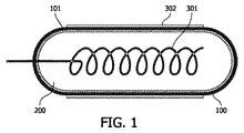
考えられうる放電管の設計には幅広いバリエーションが存在する。それはたとえば、平板、単一管、同軸管、及び、直線状、U字型、曲線状若しくは円内で巻線を形成する形状又は他の形状の放電管である。光分解反応用素子の典型的な設計は、図1及び図2のようなものである。エキシマ放電を引き起こし、かつ維持する手段としての設計は、第1型及び第2型電極を有することが重要である。巻線ワイヤが、ガス放電管100内に同心円状に挿入される。このワイヤは、この素子の第1つまり内側電極301を形成する。ガラスの外側は、小さなメッシュを構成するワイヤで覆われている。このワイヤが第2のつまり外側電極302を形成する。放電管はガス封止シールで密閉されている。放電管内部の空間はキセノン又はキセノン含有ガスで満たされる。2の電極は交流電源の両極に接続する。放電管内の圧力及びガスの組成と共に電極の幾何学的形状は、交流電源の特性に適合する。
There are a wide variety of possible discharge tube designs. It is, for example, a flat plate, a single tube, a coaxial tube, and a discharge tube of a shape that forms a winding in a straight, U-shaped, curved or circular shape or other shapes. A typical design of the photodegradation reaction element is as shown in FIGS. It is important that the design as a means to cause and maintain excimer discharge has first and second type electrodes. Winding wires are concentrically inserted into the
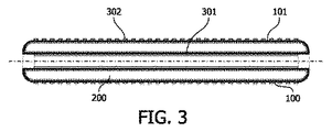
光分解反応のための別な典型的設計は同軸設計である。水又は空気流は、そのような同軸設計放電管を介して中心を流れる。これは図3及び図4に図示されている。放電管100はガラスで作られた2の同軸主部を有する。これらの同軸主部は、ガラスを密着させる方法で1つにされ、中空構造のスリーブを形成する。ガラス製の2の同軸主部間の環状ギャップは放電空間200を形成する。その空間200はキセノン又はキセノン含有ガスによって満たされる。被処理流体媒質は、内側の管を通って、第1型である透明電極301が堆積されている内壁へ流れて良い。被処理媒質はまた外側の管の外側に存在しても良い。ガラスの外側は、小さなメッシュを構成するワイヤで覆われている。このワイヤが第2のつまり外側電極302を形成する。電力供給は、これら2の電極と接続する交流電源によって供される。
Another typical design for the photolysis reaction is a coaxial design. Water or air flow flows through the center through such a coaxial design discharge tube. This is illustrated in FIGS. 3 and 4. The
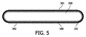
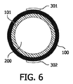
別な型の作製容易な設計が、図5及び図6に図示されている。 Another type of easy-to-manufacture design is illustrated in FIGS.
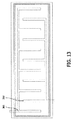
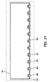
図13及び図14に図示された平板設計(“平板ランプ”)は、表面のドライクリーニング及び塗装仕上げの硬化に特に適している。 The flat plate design (“flat lamp”) illustrated in FIGS. 13 and 14 is particularly suitable for surface dry cleaning and hardening of paint finishes.
図5及び図6に図示された設計では、電極はガス放電管の壁内部に設けられている。またこれらの電極は、誘電材料からなる被覆層102によって、ガス放電空間200から隔離されている。この誘電被覆層102は、ガラス用はんだを有することが好ましい。
In the designs illustrated in FIGS. 5 and 6, the electrodes are provided inside the walls of the gas discharge tube. These electrodes are isolated from the
放電管に用いられる材料は、石英又はUV-C及びVUV放射線に対して透明な型のガラスであることが好ましい。 The material used for the discharge tube is preferably quartz or a type of glass that is transparent to UV-C and VUV radiation.
エキシマ放電を引き起こし、かつ維持する手段は、第1型及び第2型の電極を有する。好適設計では、第1型及び第2型電極は、誘電体によって抑制された放電を発生させるため、放電管の壁上に備えられている。ここで少なくとも1の電極は、誘電材料によって放電空間から隔離されている。少なくとも1の電極が、誘電バリヤによって放電空間から隔離されている設計において、適切な交流電圧が印加されるときには、無声放電が、充填ガス中で引き起こされる。 The means for causing and maintaining the excimer discharge includes first and second type electrodes. In a preferred design, the first and second type electrodes are provided on the wall of the discharge tube to generate a discharge suppressed by the dielectric. Here, at least one electrode is isolated from the discharge space by a dielectric material. In designs where at least one electrode is isolated from the discharge space by a dielectric barrier, a silent discharge is caused in the fill gas when a suitable alternating voltage is applied.
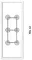
図11及び図12に図示された設計において、適切な直流又は交流電圧が電極に印加されるときには、コロナ型の放電が、充填ガス中で引き起こされる。コロナ型の放電に適した設計では、第1型及び第2型の電極は、誘電材料層によって放電空間から隔離されている必要はない。 In the designs illustrated in FIGS. 11 and 12, when an appropriate direct or alternating voltage is applied to the electrodes, a corona-type discharge is caused in the fill gas. In a design suitable for corona-type discharge, the first-type and second-type electrodes need not be separated from the discharge space by a dielectric material layer.
無声放電とコロナ放電のいずれの場合でも、適切なガス充填物が存在する場合には、ガス圧力及び電極の幾何学的形状に関係なく、エキシマ、つまり励起状態でのみ安定な分子、を含むプラズマが生成される。 In both silent and corona discharges, an excimer, a molecule that is stable only in an excited state, is available, regardless of gas pressure and electrode geometry, in the presence of an appropriate gas filling. Is generated.
電極は、たとえばアルミニウム若しくは銀のような金属、金属合金、又はITOのような透明導電性無機化合物で構成される。これらは、コーティング、上を覆うホイル、上を覆うホイの細片、ワイヤ若しくはワイヤメッシュの形態をとって良い。 The electrode is composed of a metal such as aluminum or silver, a metal alloy, or a transparent conductive inorganic compound such as ITO. These may take the form of coatings, overlying foils, overlying hoi strips, wires or wire mesh.
たとえば水のような透明電解質を電極のうちの一として用いることも可能である。これは、水中での光分解プロセスにとって特に有利である。その理由は、放射線は、このように、被処理媒質のすぐ近くで生成されるからである。 For example, a transparent electrolyte such as water can be used as one of the electrodes. This is particularly advantageous for photolysis processes in water. The reason is that the radiation is thus generated in the immediate vicinity of the medium to be processed.
他の好適実施例では、第1型及び第2型の電極は、コロナ放電を発生させるため、放電管の壁上に備えられている。 In another preferred embodiment, first and second type electrodes are provided on the wall of the discharge tube to generate a corona discharge.
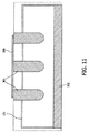
所与の方向に光強度を集光するには、放電管の一部には、VUV及びUV-C光の反射体400として機能するコーティングが供されて良い。表面の手段によって内向き又は外向きの放射線を増大させるため、UV反射体は、図9又は図10で図示された設計に用いられるのが好ましい。
To collect the light intensity in a given direction, a portion of the discharge tube may be provided with a coating that functions as a
必要な場合にUVに対して透明な保護層が供される金属表面は、UV-C又はVUV範囲の放射線の反射体として用いられるのに適している。たとえばフッ化マグネシウムがコーティングされているアルミニウムが適している。 Metal surfaces that are provided with a UV transparent protective layer when needed are suitable for use as reflectors of radiation in the UV-C or VUV range. For example, aluminum coated with magnesium fluoride is suitable.
反射体として機能するコーティングの他の適切な形態は、MgO、SiO2、Al2O3、ZnO及びTiO2からなる群から選択される材料の粒子を含むコーティングである。UV-C及びVUV放射線の反射体として機能し、金属材料からなる大面積の第1型及び第2型の電極に係る設計もいくつか存在する。この型の設計は、図11の例によって図示されている。 Another suitable form of coating that functions as a reflector is a coating comprising MgO, the particles of material selected from SiO 2, Al 2 O 3, ZnO and the group consisting of TiO 2. There are also several designs for large-area first-type and second-type electrodes that function as reflectors for UV-C and VUV radiation and are made of metallic materials. This type of design is illustrated by the example of FIG.
放電管は、キセノン又は酸素を含まないキセノンを含む混合気体で満たされることが好ましい。その理由は次の通りである。Xeの第1励起エネルギー領域内である8.4eVで、キセノン含有雰囲気中でのエキシマ放電の電子エネルギー分布濃度はかなり大きくなる。よってこの分布は理想的にはXe2エキシマの生成と一致するので、160nmから190nmの波長範囲でXe2エキシマが発光する結果として、活性剤としてのビスマス、プラセオジウム、又はネオジウムを含むリン光体の励起と一致するからである。 The discharge tube is preferably filled with a gas mixture containing xenon or oxygen-free xenon. The reason is as follows. At 8.4 eV, which is in the first excitation energy region of Xe, the electron energy distribution concentration of excimer discharge in a xenon-containing atmosphere becomes considerably large. Thus, this distribution ideally coincides with the production of Xe 2 excimer, so that Xe 2 excimer emits light in the wavelength range of 160 to 190 nm, resulting in phosphors containing bismuth, praseodymium, or neodymium as activators. This is because it coincides with excitation.
放電管の内壁は、本発明に従ったリン光体を有する発光材料のコーティング101で、部分的又は全体的に覆われる。コーティングはまた、有機又は無機の結合剤又は結合剤組成物をも含んで良い。さらにリン光体層は、保護層の手段による放電による攻撃から保護されて良い。
The inner wall of the discharge tube is partially or totally covered with a
本発明に従うと、一般式が(Y1-x-y-zLuxScyAz)PO4で表される母体格子を有するUVCリン光体を有する殺菌目的の発光材料が供されて良い。ここで、0≦x<1、0<y≦1、0<z≦0.05で、かつAはビスマス、プラセオジウム、及びネオジウムからなる群から選択される活性剤である。 According to the present invention, the general formula (Y 1-xyz Lu x Sc y A z) luminescent material sterilization purposes having a UVC phosphor having a host lattice represented by PO 4 can be provided. Here, 0 ≦ x <1, 0 <y ≦ 1, 0 <z ≦ 0.05, and A is an activator selected from the group consisting of bismuth, praseodymium, and neodymium.
この族のリン光体材料は3元の希土類金属正リン酸塩の活性化による発光に基づいている。結晶性固体は、イットリウム、ルテチウム、スカンジウムの正リン酸塩の母体格子で構成される。この正リン酸塩は、ビスマス、プラセオジウム及びネオジウムから選択される少量のドーパントによって活性化される。 This family of phosphor materials is based on light emission by activation of ternary rare earth metal orthophosphates. The crystalline solid is composed of a matrix of orthophosphates of yttrium, lutetium, and scandium. This orthophosphate is activated by a small amount of dopant selected from bismuth, praseodymium and neodymium.
母体格子はリン酸イットリウム鉱型の結晶構造を形成する。リン酸イットリウム鉱の結晶構造は、モナザイト、パープライト及びリチオフィライトと共に無水リン酸塩と通称されているリン酸塩の群に属する。また注目すべき点として、リン酸イットリウム鉱は、水分子、水酸化物又は塩化物を含む数少ないリン酸塩鉱物の1つである。 The matrix lattice forms a yttrium phosphate ore crystal structure. The crystal structure of yttrium phosphate belongs to the group of phosphates commonly referred to as anhydrous phosphate along with monazite, perplite and lithiophyllite. It should also be noted that yttrium phosphate ore is one of the few phosphate minerals containing water molecules, hydroxides or chlorides.
その構造は、リン酸塩陰イオンを置換する少量のバナジウム酸塩及びヒ酸塩を含んで良い。実際その構造は、これらの陰イオンを有する一連の固溶体を形成する。一連の固溶体が主要な陰イオンを含むことは一般的ではない。それは完全な一連の固溶体ではない。 The structure may contain small amounts of vanadate and arsenate that replace the phosphate anion. In fact, its structure forms a series of solid solutions with these anions. It is uncommon for a series of solid solutions to contain major anions. It is not a complete series of solid solutions.
その構造は、たとえばTi、Er、La、Al、Si、Zrのような少量の不純物をさらに有して良い。 The structure may further include a small amount of impurities such as Ti, Er, La, Al, Si, Zr.

母体格子は少なくとも1の物質でドーピングされる。その物質は従来活性剤と呼ばれ、発光中心として機能するものである。活性剤を適切に選ぶことで、意図したように、光学スペクトルに影響を与えることができる。 The matrix lattice is doped with at least one substance. The substance is conventionally called an activator and functions as a luminescent center. Appropriate selection of the activator can affect the optical spectrum as intended.
本発明に従うと、これらの格子中において基底状態と励起状態との間に大きなエネルギー分裂を有する活性剤が用いられる。そのような活性剤は、Bi3+、Pr3+、及びNd3+である。 According to the invention, activators are used that have a large energy split between the ground state and the excited state in these lattices. Such activators are Bi 3+ , Pr 3+ and Nd 3+ .
ビスマス、プラセオジウム、及びネオジウムは、この型の母体格子にとって優れた活性剤である。その理由は、基底状態と励起状態の両方が、母体格子のバンドギャップである約6eVの範囲内に存在するからである。これらの活性剤は一般的に、真空紫外(VUV)において広い吸収帯を示す。 Bismuth, praseodymium, and neodymium are excellent activators for this type of host lattice. The reason is that both the ground state and the excited state are in the range of about 6 eV, which is the band gap of the host lattice. These activators generally exhibit a broad absorption band in the vacuum ultraviolet (VUV).
本発明に従ったUV-Cリン光体の発光スペクトルは、YPO4:Biについての既知の発光スペクトルに相似する。このスペクトルは、225nmから275nmでの活性剤の5d4f遷移に起因する発光スペクトルを示す。しかし、たとえばLu3+及びSc3+のような小さな陽イオンを塩基性YPO4に加えることで、発光帯が広がり、かつ発光スペクトルにおいて長波長側での相対的な発光強度が改善されることで、GAC曲線との重なりがかなりの程度改善されることが分かった。より小さな同数の電子を有する陽イオンを導入することによって帯域が拡がるのは、小さな陽イオンを塩基性母体格子へドーピングすることによる電子雲拡大効果(nephelauxetic effect)によって引き起こされるものと考えられる。 The emission spectrum of the UV-C phosphor according to the present invention is similar to the known emission spectrum for YPO4: Bi. This spectrum shows the emission spectrum due to the 5d4f transition of the activator from 225 nm to 275 nm. However, adding small cations such as Lu 3+ and Sc 3+ to basic YPO 4 broadens the emission band and improves the relative emission intensity on the longer wavelength side in the emission spectrum. It was found that the overlap with the GAC curve was improved to a considerable extent. The band broadening by introducing a cation having the same number of electrons is thought to be caused by the nephelauxetic effect by doping the small host ion into the basic matrix lattice.
いずれにせよUV-Cリン光体の効率は、中間のドーピングレベルについてはほとんど減少しない。 In any case, the efficiency of the UV-C phosphor is hardly reduced for intermediate doping levels.
下表は、発光帯位置及びGAC曲線との重なりをまとめたものである。 The table below summarizes the overlap with the emission band position and GAC curve.
リン光体は、開始化合物からの固相反応によって生成される。そのリン光体の状態は、平均集団直径(mean mass diameter)d50が1μmから6μmの好適粒径分布を有する微粒子粉末である。平均集団直径d50とは、数にして50%の粒子が小さな直径を有し、その一方で数にして50%の粒子が大きな直径を有する場合での直径として定義される。 The phosphor is generated by a solid phase reaction from the starting compound. The state of the phosphor is a fine particle powder having a preferred particle size distribution with an average mass diameter d 50 of 1 μm to 6 μm. The average population diameter d 50 is defined as the diameter where 50% of the particles have a small diameter while 50% of the particles have a large diameter.
リン光体粉末は、フローコーティングプロセスによって、放電管の壁に堆積される。フローコーティングプロセス用のコーティング懸濁物は、水又はブチルアセテートのような有機化合物を溶媒として含む。たとえば安定剤、液化剤、及びセルロース誘導体のような補助物を加えることによって、懸濁物は安定化し、そのレオロジー特性が作用する。リン光体懸濁物は薄膜として放電管の壁に成膜され、乾燥され、かつ600℃で加熱される。続いて放電管は、圧力が約200mbarから300mbarのキセノンによって満たされ、かつ密閉される。 The phosphor powder is deposited on the wall of the discharge tube by a flow coating process. The coating suspension for the flow coating process contains water or an organic compound such as butyl acetate as a solvent. For example, by adding adjuvants such as stabilizers, liquefaction agents, and cellulose derivatives, the suspension is stabilized and its rheological properties act. The phosphor suspension is deposited as a thin film on the wall of the discharge tube, dried and heated at 600 ° C. The discharge tube is then filled with xenon with a pressure of about 200 mbar to 300 mbar and sealed.
(Y0.945Sc0.05)PO4:Bi0.005の合成
20gのY2O3、0.64463gのSc2O3、及び0.2184gのBi2O3が水ベースの懸濁物に加えられる。ゆっくりと22.692gのH3PO4(85%)が加えられる。混合物は室温で24時間攪拌される。溶媒は回転式蒸発器を用いることによって除去される。残った固体は100℃で乾燥される。粉末を乳鉢中で挽きながら0.400gのLiFが加えられる。焼成は、以下の温度プロファイルを用いて実行される。その温度プロファイルは、2時間で800℃まで加熱し、2時間保持し、2時間で1000℃まで加熱し、2時間保持し、最後は4時間欠けて室温まで冷却する。その結果生成された生成物は、メノウ乳鉢を用いて再度挽かれる。その後、600ml水中で140mlのHNO3溶液を用いることによって洗浄される。粉末は、吸引濾過によって分離され、酸を除去するために水で洗浄され、かつ100℃で乾燥される。続いてリン光体は挽かれる。そのリン光体は、挽かれた後に、開いたるつぼ中において900℃で2時間、再度大気中で焼成される。粒子表面から余分なビスマスを除去するため、リン光体は、0.1mol/LのEDTA溶液500mlによって2時間洗浄される。続いてリン光体は濾紙上で回収され、水で洗浄されて、最終的には100℃で乾燥される。
Synthesis of (Y 0.945 Sc 0.05 ) PO 4 : Bi 0.005
20 g Y 2 O 3 , 0.64463 g Sc 2 O 3 , and 0.2184 g Bi 2 O 3 are added to the water-based suspension. Slowly 22.692 g of H 3 PO 4 (85%) is added. The mixture is stirred at room temperature for 24 hours. The solvent is removed by using a rotary evaporator. The remaining solid is dried at 100 ° C. 0.400 g LiF is added while grinding the powder in a mortar. Firing is performed using the following temperature profile. The temperature profile is heated to 800 ° C. in 2 hours, held for 2 hours, heated to 1000 ° C. in 2 hours, held for 2 hours, and finally cooled for 4 hours lacking for 4 hours. The resulting product is ground again using an agate mortar. It is then washed by using 140 ml of HNO 3 solution in 600 ml water. The powder is separated by suction filtration, washed with water to remove the acid and dried at 100 ° C. The phosphor is then ground. After being ground, the phosphor is fired again in the atmosphere for 2 hours at 900 ° C. in an open crucible. To remove excess bismuth from the particle surface, the phosphor is washed with 500 ml of a 0.1 mol / L EDTA solution for 2 hours. Subsequently, the phosphor is recovered on the filter paper, washed with water and finally dried at 100 ° C.
(Y0.945Sc0.05)PO4:Bi0.005の励起及び発光スペクトルは図16に与えられている。 The excitation and emission spectra of (Y 0.945 Sc 0.05 ) PO 4 : Bi 0.005 are given in FIG.
Xeエキシマランプの製法
結合剤としてニトロセルロースを有するブチルアセテート中の(Y0.945Sc0.05)PO4:Bi0.005の懸濁物が生成される。リン光体懸濁物は、フローコーティングプロセスによって、内径が5mmの合成石英管(スプラシル(Suprasil)(商標))の内壁に塗布される。リン光体層の厚さは、3mg/cm3のリン光体についての単位面積あたりの重さに対応する。結合剤は、580℃よりも低温で焼かれて除去される。素子は、200から300mbarの圧力のキセノンで満たされ、その後密閉される。酸素による如何なる汚染も慎重に回避されなければならない。アルミニウムホイルからなる2の電極は、素子外壁に対して対角状に結合する。
Xe Excimer Lamp Preparation A suspension of (Y 0.945 Sc 0.05 ) PO 4 : Bi 0.005 in butyl acetate with nitrocellulose as binder is produced. The phosphor suspension is applied to the inner wall of a synthetic quartz tube (Suprasil ™) with an inner diameter of 5 mm by a flow coating process. The thickness of the phosphor layer corresponds to the weight per unit area for a 3 mg / cm 3 phosphor. The binder is removed by baking at a temperature below 580 ° C. The element is filled with xenon at a pressure of 200 to 300 mbar and then sealed. Any contamination with oxygen must be carefully avoided. The two electrodes made of aluminum foil are diagonally coupled to the outer wall of the element.
素子は、方形波特性、6kVの振幅、及び25kHzの周波数を有する交流電流によって動作する。 The device operates with an alternating current having a square wave characteristic, an amplitude of 6 kV, and a frequency of 25 kHz.
動作時において、交流電圧が電極に印加されるとき、好適にはキセノン含有ガスである充填ガス中で無声放電が引き起こされる。その結果、キセノンエキシマ、つまり励起状態でのみ安定な分子、がプラズマの状態、つまりXe+Xe*=Xe2 *の状態で生成される。 In operation, when an alternating voltage is applied to the electrodes, a silent discharge is caused in the fill gas, which is preferably a xenon-containing gas. As a result, a xenon excimer, that is, a molecule that is stable only in an excited state, is generated in a plasma state, that is, Xe + Xe * = Xe 2 * .
励起エネルギーは、波長λ=140〜190nmであるVUV放射線として再度放出される。このような電子エネルギーのVUV放射線への変換は、すぐれた効率で実行される。発生したVUV光子はリン光体によって吸収される。励起エネルギーは、スペクトルの長波長範囲で部分的に再度放出される。Bi(III)、Nd(III)、又はPr(III)で活性化されるリン光体の吸収係数は、キセノンが放射する範囲の波長で特に高い。また量子収率も大きい。母体格子は、母体格子の吸収及び活性剤へのエネルギー移行以外の発光過程に関与しない。しかし母体格子は、活性化イオンのエネルギー準位の厳密な位置、すなわち吸収及び発光波長、に影響を及ぼす。 The excitation energy is emitted again as VUV radiation with a wavelength λ = 140-190 nm. This conversion of electron energy into VUV radiation is performed with excellent efficiency. The generated VUV photons are absorbed by the phosphor. The excitation energy is partially re-emitted in the long wavelength range of the spectrum. The absorption coefficient of phosphors activated by Bi (III), Nd (III), or Pr (III) is particularly high at wavelengths in the range emitted by xenon. The quantum yield is also large. The matrix lattice is not involved in the light emission process other than the absorption of the matrix lattice and the energy transfer to the active agent. However, the host lattice affects the exact position of the energy level of the activated ions, ie the absorption and emission wavelengths.
上述の素子はまた、高収率の光分解反応物にも非常に適している。放出される放射線のスペクトルが狭い帯域に閉じこめられているため、本発明に従った素子は、波長選択光反応を実行するのに有利に用いられて良い。 The devices described above are also very suitable for high yield photolysis reactants. Since the spectrum of emitted radiation is confined to a narrow band, the device according to the invention can be advantageously used to carry out wavelength selective photoreactions.
本発明に従った素子は、汚水が被処理流体である場合には、水及び汚水技術と共に用いられなければならない。この種類の列挙できる処理例は、a)消毒、b)汚染物質及び色素の破壊、及びc)においの除去、である。 The element according to the invention must be used with water and sewage technology when sewage is the fluid to be treated. Examples of treatments that can be listed of this type are a) disinfection, b) destruction of contaminants and pigments, and c) odor removal.
本発明に従った素子はまた、他の液体及び溶媒を殺菌するのにも用いられて良い。 The device according to the invention may also be used to sterilize other liquids and solvents.
図1及び図2に図示された設計の場合では、被処理媒質は、放射線源の外側面を通過して導かれて良い。別の用途では、この設計はたとえば、乾燥状態での表面クリーニングに用いられて良い。 In the case of the designs illustrated in FIGS. 1 and 2, the treated medium may be guided through the outer surface of the radiation source. In other applications, this design may be used, for example, for surface cleaning in the dry state.
図3及び図4に図示された設計の場合では、反応媒質は、放射線源の内側及び/又は外側面を通過して導かれて良い。内側面での照射を可能にするためには、ランプの軸に隣接する電極は透明又は穴が開いていなければならない。この設計は、水中、又は空気中、又は他のガス中で溶媒残余物を破壊するのに用いられて良い。 In the case of the design illustrated in FIGS. 3 and 4, the reaction medium may be directed through the inner and / or outer surface of the radiation source. In order to allow illumination on the inside surface, the electrode adjacent to the axis of the lamp must be transparent or perforated. This design may be used to destroy solvent residues in water or air or other gases.
Claims (11)
ガス充填物で満たされている放電空間を有する、UVに対して少なくとも部分的に透明な放電管、
前記放電空間内でエキシマ放電を引き起こして、かつそれを維持する手段、及び、
0≦x<1、0<y≦1、0<z≦0.05で、かつAはビスマス、プラセオジウム、及びネオジウムからなる群から選択される活性剤であるところ、一般式が(Y1-x-y-zLuxScyAz)PO4で表される母体格子を有するリン光体を含むコーティング、
が備えられる紫外放射線発生素子。 An element that generates ultraviolet radiation by excimer discharge means,
A discharge tube at least partially transparent to UV, having a discharge space filled with a gas filling,
Means for causing and maintaining an excimer discharge in the discharge space; and
Where 0 ≦ x <1, 0 <y ≦ 1, 0 <z ≦ 0.05, and A is an activator selected from the group consisting of bismuth, praseodymium, and neodymium, the general formula is (Y 1-xyz Lu x Sc y A z ) A coating comprising a phosphor having a host lattice represented by PO 4 ,
An ultraviolet radiation generating element.
Applications Claiming Priority (3)
| Application Number | Priority Date | Filing Date | Title |
|---|---|---|---|
| EP05102948 | 2005-04-14 | ||
| EP05102948.6 | 2005-04-14 | ||
| PCT/IB2006/051097 WO2006109238A2 (en) | 2005-04-14 | 2006-04-11 | Device for generating uvc radiation |
Publications (2)
| Publication Number | Publication Date |
|---|---|
| JP2008536282A true JP2008536282A (en) | 2008-09-04 |
| JP5074381B2 JP5074381B2 (en) | 2012-11-14 |
Family
ID=36972996
Family Applications (1)
| Application Number | Title | Priority Date | Filing Date |
|---|---|---|---|
| JP2008506026A Expired - Fee Related JP5074381B2 (en) | 2005-04-14 | 2006-04-11 | UVC radiation generator |
Country Status (9)
| Country | Link |
|---|---|
| US (1) | US7808170B2 (en) |
| EP (1) | EP1874895B1 (en) |
| JP (1) | JP5074381B2 (en) |
| KR (1) | KR101256387B1 (en) |
| CN (1) | CN101160373B (en) |
| AT (1) | ATE407990T1 (en) |
| DE (1) | DE602006002740D1 (en) |
| TW (1) | TW200644034A (en) |
| WO (1) | WO2006109238A2 (en) |
Cited By (11)
| Publication number | Priority date | Publication date | Assignee | Title |
|---|---|---|---|---|
| JP2011009090A (en) * | 2009-06-26 | 2011-01-13 | Ushio Inc | Discharge lamp device |
| JP2013536545A (en) * | 2010-07-13 | 2013-09-19 | コーニンクレッカ フィリップス エヌ ヴェ | UV-A or UV-B radiation discharge lamp |
| JP2013231142A (en) * | 2012-05-01 | 2013-11-14 | Daiden Co Ltd | Uv-emitting phosphor and light-emitting element using the same |
| JP2014500890A (en) * | 2010-10-22 | 2014-01-16 | コーニンクレッカ フィリップス エヌ ヴェ | Luminescent substance and light emitting device having the luminescent substance |
| JP2014129452A (en) * | 2012-12-28 | 2014-07-10 | Daiden Co Ltd | Ultraviolet emission phosphor and light-emitting device using the same |
| WO2018235723A1 (en) * | 2017-06-20 | 2018-12-27 | 大電株式会社 | Ultraviolet light emitting phosphor, light emitting element, and light emitting device |
| WO2020129916A1 (en) * | 2018-12-17 | 2020-06-25 | 浜松ホトニクス株式会社 | Uv-emitting phosphor, method for producing same, and uv excitation light source |
| WO2020129856A1 (en) * | 2018-12-17 | 2020-06-25 | 浜松ホトニクス株式会社 | Ultraviolet light generation target, method for manufacturing ultraviolet light generation target, and electron-beam-excited ultraviolet light source |
| WO2022059641A1 (en) * | 2020-09-15 | 2022-03-24 | 浜松ホトニクス株式会社 | Method of manufacturing light emitter, light emitter and ultraviolet light source |
| WO2023132179A1 (en) * | 2022-01-04 | 2023-07-13 | 浜松ホトニクス株式会社 | Production method for uv light-emitting body, uv light-emitting body, and uv light source |
| WO2024166702A1 (en) * | 2023-02-06 | 2024-08-15 | 株式会社紫光技研 | Ultraviolet light emitting element and ultraviolet light irradiation device |
Families Citing this family (26)
| Publication number | Priority date | Publication date | Assignee | Title |
|---|---|---|---|---|
| US8257612B2 (en) | 2007-07-05 | 2012-09-04 | Cabot Corporation | Compositions having multiple responses to excitation radiation and methods for making same |
| KR101158962B1 (en) * | 2007-10-10 | 2012-06-21 | 우시오덴키 가부시키가이샤 | Excimer lamp |
| US20090143842A1 (en) * | 2007-11-02 | 2009-06-04 | Cumbie William E | Phototherapy Treatment and Device for Infections, Diseases, and Disorders |
| JP2009120405A (en) * | 2007-11-09 | 2009-06-04 | Canon Inc | Glass composition for ultraviolet light and optical device using the same |
| CN102325565B (en) * | 2009-01-29 | 2016-05-04 | S·E·内斯特尔 | Improved method and apparatus for producing high levels of disinfection in air and surfaces |
| US20130289132A1 (en) * | 2011-01-04 | 2013-10-31 | Koninklijke Philips N.V. | Uv-emitting phosphors |
| WO2012104750A2 (en) * | 2011-02-04 | 2012-08-09 | Koninklijke Philips Electronics N.V. | Novel scintillator materials for neutron detectors |
| EP2726572A1 (en) | 2011-06-29 | 2014-05-07 | Koninklijke Philips N.V. | Luminescent material particles comprising a coating and lighting unit comprising such luminescent material |
| US9987499B2 (en) | 2013-05-13 | 2018-06-05 | Philips Lighting Holding B.V. | UV radiation device |
| KR101416146B1 (en) * | 2013-05-30 | 2014-07-09 | 한국화학연구원 | UV-C emitting yttrium lanthanium phosphate phosphor |
| US9947526B2 (en) | 2015-02-03 | 2018-04-17 | Shikoh Tech Llc | Gas discharge device and flat light source using the same, and driving method therefor |
| WO2017082380A1 (en) * | 2015-11-13 | 2017-05-18 | ウシオ電機株式会社 | Deodorizing method and deodorizing device |
| US10128100B2 (en) | 2015-11-30 | 2018-11-13 | Shikoh Tech Llc | Drive method and drive circuit for light-emitting device using gas discharge, and ultraviolet irradiation device |
| SE539934C2 (en) * | 2016-06-22 | 2018-01-23 | Lightlab Sweden Ab | System for treating a fluid with non-mercury-based UV light |
| SE540283C2 (en) | 2016-12-08 | 2018-05-22 | Lightlab Sweden Ab | A field emission light source adapted to emit UV light |
| JP6837834B2 (en) * | 2016-12-28 | 2021-03-03 | 浜松ホトニクス株式会社 | Target for generating ultraviolet light, its manufacturing method, and electron beam-excited ultraviolet light source |
| BR112020008148A2 (en) * | 2017-10-24 | 2020-11-03 | Infuser Ip Aps | an air treatment system and a method of using said air treatment system |
| WO2019151364A1 (en) * | 2018-02-02 | 2019-08-08 | 株式会社エンプラス | Ultraviolet sterilization tube and ultraviolet sterilization device |
| KR102116867B1 (en) | 2018-05-08 | 2020-05-29 | 주식회사 원익큐엔씨 | Surface treatment device for implant |
| EP3623446A1 (en) | 2018-09-13 | 2020-03-18 | Xylem Europe GmbH | A phosphor for a uv emitting device and a uv generating device utilizing such a phosphor |
| EP3703104A1 (en) * | 2019-02-27 | 2020-09-02 | Xylem Europe GmbH | A phosphor combination for a uv emitting device and a uv generating device utilizing such a phosphor combination |
| US11786622B2 (en) | 2020-05-08 | 2023-10-17 | Ultra-Violet Solutions, Llc | Far UV-C light apparatus |
| EP4171342A4 (en) | 2020-06-26 | 2024-07-31 | Ali Shambayati | HYBRID LAMP WITH FAR UV-C RADIATION AND VISIBLE LIGHT |
| WO2022069584A1 (en) * | 2020-10-01 | 2022-04-07 | Fachhochschule Münster | Material for gas discharge lamps |
| KR20220046839A (en) | 2020-10-08 | 2022-04-15 | 부경대학교 산학협력단 | UV-emitting MOS structure electroluminescent deveice and its manufacturing method |
| DE102024107820A1 (en) * | 2023-03-23 | 2024-09-26 | Orc Manufacturing Co., Ltd. | EXCIMER LAMP AND UV IRRADIATION UNIT WITH THIS LAMP |
Citations (2)
| Publication number | Priority date | Publication date | Assignee | Title |
|---|---|---|---|---|
| JP2001015078A (en) * | 1999-04-28 | 2001-01-19 | Koninkl Philips Electronics Nv | Water sterilizer |
| JP2003022783A (en) * | 2001-06-20 | 2003-01-24 | Koninkl Philips Electronics Nv | Low-pressure gas electric discharge lamp which has fluorescence coating |
Family Cites Families (8)
| Publication number | Priority date | Publication date | Assignee | Title |
|---|---|---|---|---|
| GB1200935A (en) | 1966-10-31 | 1970-08-05 | Gen Electric | Improvements in rare earth phosphors activated with bismuth |
| US3825792A (en) * | 1973-07-03 | 1974-07-23 | Westinghouse Electric Corp | Novel discharge lamp and coating |
| US4171501A (en) * | 1973-10-22 | 1979-10-16 | Hitachi, Ltd. | Light emitting devices based on the excitation of phosphor screens |
| JP3988337B2 (en) * | 1999-10-01 | 2007-10-10 | 株式会社日立製作所 | Phosphorus / vanadate phosphor, display device using the same, and light emitting device |
| DE10106963A1 (en) * | 2001-02-15 | 2002-08-29 | Philips Corp Intellectual Pty | Plasma screen with increased luminance |
| DE10209191A1 (en) | 2002-03-04 | 2003-09-18 | Philips Intellectual Property | Device for generating UV radiation |
| US7205710B2 (en) | 2002-05-29 | 2007-04-17 | Koninklijke Philips Electronics, N.V. | Fluorescent lamp with ultraviolet reflecting layer |
| US6982046B2 (en) | 2003-10-01 | 2006-01-03 | General Electric Company | Light sources with nanometer-sized VUV radiation-absorbing phosphors |
-
2006
- 2006-04-11 DE DE602006002740T patent/DE602006002740D1/en active Active
- 2006-04-11 WO PCT/IB2006/051097 patent/WO2006109238A2/en not_active Ceased
- 2006-04-11 CN CN2006800121156A patent/CN101160373B/en not_active Expired - Fee Related
- 2006-04-11 EP EP06727875A patent/EP1874895B1/en not_active Not-in-force
- 2006-04-11 KR KR1020077025872A patent/KR101256387B1/en not_active Expired - Fee Related
- 2006-04-11 JP JP2008506026A patent/JP5074381B2/en not_active Expired - Fee Related
- 2006-04-11 TW TW095112906A patent/TW200644034A/en unknown
- 2006-04-11 AT AT06727875T patent/ATE407990T1/en not_active IP Right Cessation
- 2006-04-11 US US11/911,226 patent/US7808170B2/en active Active
Patent Citations (2)
| Publication number | Priority date | Publication date | Assignee | Title |
|---|---|---|---|---|
| JP2001015078A (en) * | 1999-04-28 | 2001-01-19 | Koninkl Philips Electronics Nv | Water sterilizer |
| JP2003022783A (en) * | 2001-06-20 | 2003-01-24 | Koninkl Philips Electronics Nv | Low-pressure gas electric discharge lamp which has fluorescence coating |
Cited By (21)
| Publication number | Priority date | Publication date | Assignee | Title |
|---|---|---|---|---|
| JP2011009090A (en) * | 2009-06-26 | 2011-01-13 | Ushio Inc | Discharge lamp device |
| JP2013536545A (en) * | 2010-07-13 | 2013-09-19 | コーニンクレッカ フィリップス エヌ ヴェ | UV-A or UV-B radiation discharge lamp |
| JP2014500890A (en) * | 2010-10-22 | 2014-01-16 | コーニンクレッカ フィリップス エヌ ヴェ | Luminescent substance and light emitting device having the luminescent substance |
| JP2013231142A (en) * | 2012-05-01 | 2013-11-14 | Daiden Co Ltd | Uv-emitting phosphor and light-emitting element using the same |
| JP2014129452A (en) * | 2012-12-28 | 2014-07-10 | Daiden Co Ltd | Ultraviolet emission phosphor and light-emitting device using the same |
| WO2018235723A1 (en) * | 2017-06-20 | 2018-12-27 | 大電株式会社 | Ultraviolet light emitting phosphor, light emitting element, and light emitting device |
| JPWO2018235723A1 (en) * | 2017-06-20 | 2019-06-27 | 大電株式会社 | Ultraviolet light emitting phosphor, light emitting element, and light emitting device |
| US11555148B2 (en) | 2017-06-20 | 2023-01-17 | Dyden Corporation | Ultraviolet-emitting phosphor, light-emitting element, and light-emitting device |
| JP2020098679A (en) * | 2018-12-17 | 2020-06-25 | 浜松ホトニクス株式会社 | Target for generating ultraviolet light, method for manufacturing the same, and electron beam excited ultraviolet light source |
| WO2020129856A1 (en) * | 2018-12-17 | 2020-06-25 | 浜松ホトニクス株式会社 | Ultraviolet light generation target, method for manufacturing ultraviolet light generation target, and electron-beam-excited ultraviolet light source |
| JP2020097639A (en) * | 2018-12-17 | 2020-06-25 | 浜松ホトニクス株式会社 | Ultraviolet light emitting phosphor, method for producing the same, and ultraviolet excitation light source |
| WO2020129916A1 (en) * | 2018-12-17 | 2020-06-25 | 浜松ホトニクス株式会社 | Uv-emitting phosphor, method for producing same, and uv excitation light source |
| JP7236859B2 (en) | 2018-12-17 | 2023-03-10 | 浜松ホトニクス株式会社 | Ultraviolet light generating target, manufacturing method thereof, and electron beam excitation ultraviolet light source |
| JP7313817B2 (en) | 2018-12-17 | 2023-07-25 | 浜松ホトニクス株式会社 | Method for producing ultraviolet light-emitting phosphor |
| US11887837B2 (en) | 2018-12-17 | 2024-01-30 | Hamamatsu Photonics K.K. | Ultraviolet light generation target, method for manufacturing ultraviolet light generation target, and electron-beam-excited ultraviolet light source |
| WO2022059641A1 (en) * | 2020-09-15 | 2022-03-24 | 浜松ホトニクス株式会社 | Method of manufacturing light emitter, light emitter and ultraviolet light source |
| JP2022048598A (en) * | 2020-09-15 | 2022-03-28 | 浜松ホトニクス株式会社 | Method of manufacturing light emitter, light emitter and ultraviolet light source |
| WO2023132179A1 (en) * | 2022-01-04 | 2023-07-13 | 浜松ホトニクス株式会社 | Production method for uv light-emitting body, uv light-emitting body, and uv light source |
| JP2023099965A (en) * | 2022-01-04 | 2023-07-14 | 浜松ホトニクス株式会社 | Method for manufacturing ultraviolet light emitter, ultraviolet light emitter, and ultraviolet light source |
| WO2024166702A1 (en) * | 2023-02-06 | 2024-08-15 | 株式会社紫光技研 | Ultraviolet light emitting element and ultraviolet light irradiation device |
| JPWO2024166702A1 (en) * | 2023-02-06 | 2024-08-15 |
Also Published As
| Publication number | Publication date |
|---|---|
| TW200644034A (en) | 2006-12-16 |
| WO2006109238A3 (en) | 2006-12-07 |
| JP5074381B2 (en) | 2012-11-14 |
| EP1874895B1 (en) | 2008-09-10 |
| US20080258601A1 (en) | 2008-10-23 |
| KR20070121044A (en) | 2007-12-26 |
| CN101160373B (en) | 2011-08-10 |
| KR101256387B1 (en) | 2013-04-25 |
| ATE407990T1 (en) | 2008-09-15 |
| EP1874895A2 (en) | 2008-01-09 |
| CN101160373A (en) | 2008-04-09 |
| DE602006002740D1 (en) | 2008-10-23 |
| WO2006109238A2 (en) | 2006-10-19 |
| US7808170B2 (en) | 2010-10-05 |
Similar Documents
| Publication | Publication Date | Title |
|---|---|---|
| JP5074381B2 (en) | UVC radiation generator | |
| US7298077B2 (en) | Device for generating UV radiation | |
| US6398970B1 (en) | Device for disinfecting water comprising a UV-C gas discharge lamp | |
| EP1532224B1 (en) | Device for generating radiation | |
| JP5569987B2 (en) | Ultraviolet light emitting material and ultraviolet light source | |
| JP5770298B2 (en) | Luminescent substance and light emitting device having the luminescent substance | |
| JP2012518698A (en) | Discharge lamp that emits UV light | |
| US20120319011A1 (en) | Mercury uv lamp with improved actinic spectrum | |
| JP5281285B2 (en) | Low pressure gas discharge lamp with UV-B phosphor | |
| JP5850539B2 (en) | Discharge lamp, method of use and system | |
| US20090223901A1 (en) | Dielectric barrier discharge lamp comprising an uv-b phosphor | |
| JP2006342336A (en) | UVC radiation Sr (Al, Mg) 12O19: Pr phosphor and lamp containing the same | |
| JPH09265940A (en) | Fluorescent lamps and lighting devices | |
| JP2005285635A (en) | Ultra violet ray lamp |
Legal Events
| Date | Code | Title | Description |
|---|---|---|---|
| A621 | Written request for application examination |
Free format text: JAPANESE INTERMEDIATE CODE: A621 Effective date: 20090407 |
|
| A977 | Report on retrieval |
Free format text: JAPANESE INTERMEDIATE CODE: A971007 Effective date: 20111124 |
|
| A131 | Notification of reasons for refusal |
Free format text: JAPANESE INTERMEDIATE CODE: A131 Effective date: 20111129 |
|
| A601 | Written request for extension of time |
Free format text: JAPANESE INTERMEDIATE CODE: A601 Effective date: 20120227 |
|
| A602 | Written permission of extension of time |
Free format text: JAPANESE INTERMEDIATE CODE: A602 Effective date: 20120305 |
|
| A521 | Request for written amendment filed |
Free format text: JAPANESE INTERMEDIATE CODE: A523 Effective date: 20120525 |
|
| A131 | Notification of reasons for refusal |
Free format text: JAPANESE INTERMEDIATE CODE: A131 Effective date: 20120619 |
|
| TRDD | Decision of grant or rejection written | ||
| A01 | Written decision to grant a patent or to grant a registration (utility model) |
Free format text: JAPANESE INTERMEDIATE CODE: A01 Effective date: 20120731 |
|
| A01 | Written decision to grant a patent or to grant a registration (utility model) |
Free format text: JAPANESE INTERMEDIATE CODE: A01 |
|
| A61 | First payment of annual fees (during grant procedure) |
Free format text: JAPANESE INTERMEDIATE CODE: A61 Effective date: 20120823 |
|
| R150 | Certificate of patent or registration of utility model |
Ref document number: 5074381 Country of ref document: JP Free format text: JAPANESE INTERMEDIATE CODE: R150 Free format text: JAPANESE INTERMEDIATE CODE: R150 |
|
| FPAY | Renewal fee payment (event date is renewal date of database) |
Free format text: PAYMENT UNTIL: 20150831 Year of fee payment: 3 |
|
| R250 | Receipt of annual fees |
Free format text: JAPANESE INTERMEDIATE CODE: R250 |
|
| R250 | Receipt of annual fees |
Free format text: JAPANESE INTERMEDIATE CODE: R250 |
|
| S111 | Request for change of ownership or part of ownership |
Free format text: JAPANESE INTERMEDIATE CODE: R313113 |
|
| S531 | Written request for registration of change of domicile |
Free format text: JAPANESE INTERMEDIATE CODE: R313531 |
|
| S533 | Written request for registration of change of name |
Free format text: JAPANESE INTERMEDIATE CODE: R313533 |
|
| R350 | Written notification of registration of transfer |
Free format text: JAPANESE INTERMEDIATE CODE: R350 |
|
| R250 | Receipt of annual fees |
Free format text: JAPANESE INTERMEDIATE CODE: R250 |
|
| R250 | Receipt of annual fees |
Free format text: JAPANESE INTERMEDIATE CODE: R250 |
|
| R250 | Receipt of annual fees |
Free format text: JAPANESE INTERMEDIATE CODE: R250 |
|
| R250 | Receipt of annual fees |
Free format text: JAPANESE INTERMEDIATE CODE: R250 |
|
| R250 | Receipt of annual fees |
Free format text: JAPANESE INTERMEDIATE CODE: R250 |
|
| R250 | Receipt of annual fees |
Free format text: JAPANESE INTERMEDIATE CODE: R250 |
|
| R250 | Receipt of annual fees |
Free format text: JAPANESE INTERMEDIATE CODE: R250 |
|
| LAPS | Cancellation because of no payment of annual fees |