JP2008534040A - Surgical guide - Google Patents
Surgical guide Download PDFInfo
- Publication number
- JP2008534040A JP2008534040A JP2008502461A JP2008502461A JP2008534040A JP 2008534040 A JP2008534040 A JP 2008534040A JP 2008502461 A JP2008502461 A JP 2008502461A JP 2008502461 A JP2008502461 A JP 2008502461A JP 2008534040 A JP2008534040 A JP 2008534040A
- Authority
- JP
- Japan
- Prior art keywords
- guide
- axis
- base
- body part
- instrument
- Prior art date
- Legal status (The legal status is an assumption and is not a legal conclusion. Google has not performed a legal analysis and makes no representation as to the accuracy of the status listed.)
- Pending
Links
Images

Classifications
-
- A—HUMAN NECESSITIES
- A61—MEDICAL OR VETERINARY SCIENCE; HYGIENE
- A61B—DIAGNOSIS; SURGERY; IDENTIFICATION
- A61B17/00—Surgical instruments, devices or methods, e.g. tourniquets
- A61B17/16—Bone cutting, breaking or removal means other than saws, e.g. Osteoclasts; Drills or chisels for bones; Trepans
- A61B17/17—Guides or aligning means for drills, mills, pins or wires
- A61B17/1721—Guides or aligning means for drills, mills, pins or wires for applying pins along or parallel to the axis of the femoral neck
-
- A—HUMAN NECESSITIES
- A61—MEDICAL OR VETERINARY SCIENCE; HYGIENE
- A61B—DIAGNOSIS; SURGERY; IDENTIFICATION
- A61B17/00—Surgical instruments, devices or methods, e.g. tourniquets
- A61B17/16—Bone cutting, breaking or removal means other than saws, e.g. Osteoclasts; Drills or chisels for bones; Trepans
- A61B17/17—Guides or aligning means for drills, mills, pins or wires
- A61B17/1703—Guides or aligning means for drills, mills, pins or wires using imaging means, e.g. by X-rays
-
- A—HUMAN NECESSITIES
- A61—MEDICAL OR VETERINARY SCIENCE; HYGIENE
- A61B—DIAGNOSIS; SURGERY; IDENTIFICATION
- A61B17/00—Surgical instruments, devices or methods, e.g. tourniquets
- A61B17/16—Bone cutting, breaking or removal means other than saws, e.g. Osteoclasts; Drills or chisels for bones; Trepans
- A61B17/17—Guides or aligning means for drills, mills, pins or wires
- A61B17/1739—Guides or aligning means for drills, mills, pins or wires specially adapted for particular parts of the body
- A61B17/1742—Guides or aligning means for drills, mills, pins or wires specially adapted for particular parts of the body for the hip
- A61B17/175—Guides or aligning means for drills, mills, pins or wires specially adapted for particular parts of the body for the hip for preparing the femur for hip prosthesis insertion
-
- A—HUMAN NECESSITIES
- A61—MEDICAL OR VETERINARY SCIENCE; HYGIENE
- A61B—DIAGNOSIS; SURGERY; IDENTIFICATION
- A61B34/00—Computer-aided surgery; Manipulators or robots specially adapted for use in surgery
- A61B34/10—Computer-aided planning, simulation or modelling of surgical operations
- A61B2034/101—Computer-aided simulation of surgical operations
- A61B2034/105—Modelling of the patient, e.g. for ligaments or bones
-
- A—HUMAN NECESSITIES
- A61—MEDICAL OR VETERINARY SCIENCE; HYGIENE
- A61B—DIAGNOSIS; SURGERY; IDENTIFICATION
- A61B34/00—Computer-aided surgery; Manipulators or robots specially adapted for use in surgery
- A61B34/10—Computer-aided planning, simulation or modelling of surgical operations
- A61B2034/107—Visualisation of planned trajectories or target regions
-
- A—HUMAN NECESSITIES
- A61—MEDICAL OR VETERINARY SCIENCE; HYGIENE
- A61B—DIAGNOSIS; SURGERY; IDENTIFICATION
- A61B34/00—Computer-aided surgery; Manipulators or robots specially adapted for use in surgery
- A61B34/20—Surgical navigation systems; Devices for tracking or guiding surgical instruments, e.g. for frameless stereotaxis
- A61B2034/2046—Tracking techniques
- A61B2034/2055—Optical tracking systems
-
- A—HUMAN NECESSITIES
- A61—MEDICAL OR VETERINARY SCIENCE; HYGIENE
- A61B—DIAGNOSIS; SURGERY; IDENTIFICATION
- A61B34/00—Computer-aided surgery; Manipulators or robots specially adapted for use in surgery
- A61B34/20—Surgical navigation systems; Devices for tracking or guiding surgical instruments, e.g. for frameless stereotaxis
-
- A—HUMAN NECESSITIES
- A61—MEDICAL OR VETERINARY SCIENCE; HYGIENE
- A61B—DIAGNOSIS; SURGERY; IDENTIFICATION
- A61B90/00—Instruments, implements or accessories specially adapted for surgery or diagnosis and not covered by any of the groups A61B1/00 - A61B50/00, e.g. for luxation treatment or for protecting wound edges
- A61B90/10—Instruments, implements or accessories specially adapted for surgery or diagnosis and not covered by any of the groups A61B1/00 - A61B50/00, e.g. for luxation treatment or for protecting wound edges for stereotaxic surgery, e.g. frame-based stereotaxis
- A61B90/11—Instruments, implements or accessories specially adapted for surgery or diagnosis and not covered by any of the groups A61B1/00 - A61B50/00, e.g. for luxation treatment or for protecting wound edges for stereotaxic surgery, e.g. frame-based stereotaxis with guides for needles or instruments, e.g. arcuate slides or ball joints
Abstract
【課題】外科用のガイドおよびこれを用いるコンピュータ支援外科手術法が開示される。
【解決手段】ガイドは、器具をガイド軸線に沿って案内するよう身体部分に取り付けられている。本体にはチャネルが設けられ、このチャネルは、ガイド軸線を定めると共に使用の際に器具を受け入れる。ベースが、使用の際に身体部分に取り付けられると身体部分の表面に係合し、身体部分に関する入口箇所上に本体を支持し、この場合、ガイド軸線は、入口箇所を通る。旋回機構体が、本体をベースに取り付ける。本体は、旋回することによってしかベースに対して動くことができない。ガイドは、入口箇所が本体の旋回の中心である運動の中心であるように構成されている。
【選択図】図1A surgical guide and a computer assisted surgical method using the same are disclosed.
A guide is attached to the body part to guide the instrument along a guide axis. The body is provided with a channel that defines a guide axis and receives the instrument in use. When the base is attached to the body part in use, it engages the surface of the body part and supports the body on the entry point with respect to the body part, where the guide axis passes through the entry point. A turning mechanism attaches the body to the base. The body can only move relative to the base by turning. The guide is configured such that the entrance location is the center of movement, which is the center of rotation of the body.
[Selection] Figure 1
Description
〔分野〕
本発明は、ガイドに関し、特に、身体部分に対する軸線を定める際に用いられ、特に、コンピュータ支援外科手術手技に用いられるのに適した外科手術用のガイドに関する。
[Field]
The present invention relates to a guide, and more particularly to a surgical guide that is used in defining an axis for a body part, and particularly suitable for use in computer-assisted surgical procedures.
〔背景〕
外科手術手技中、器具またはツールを、医療技師により、特定の場所および/または特定の向きで身体部分に取り付けられるようにするのを助けるためのガイドを用いるのが良い。ガイドは、ガイドを使用中に調節できるよう種々の自由度を提供する機構体を有していても良い。これにより、使用の際に融通性が得られるが、これにより、実際のガイドの使いやすさが低下すると共に、ガイドのサイズおよび複雑さが増す。さらに、ガイドを骨にしっかりと取り付けるのが困難な場合がある。それ故、ガイドを狭い手術部位のところに用いることができない場合がある。さらに、調節機構体は、現場で医療技師により、接近可能ではない場合がある。さらに又、ガイドの機械的複雑さにより機械的故障の恐れがいっそう高くなる。
〔background〕
During a surgical procedure, a guide may be used to help the instrument or tool be attached to the body part at a specific location and / or in a specific orientation by a medical technician. The guide may have a mechanism that provides various degrees of freedom so that the guide can be adjusted during use. This provides flexibility in use, but this reduces the ease of use of the actual guide and increases the size and complexity of the guide. In addition, it may be difficult to securely attach the guide to the bone. Therefore, the guide may not be used at narrow surgical sites. Further, the adjustment mechanism may not be accessible by a medical technician at the site. Furthermore, the mechanical complexity of the guide increases the risk of mechanical failure.
それ故、単純で調節可能な外科手術用ガイド、特に、コンピュータ支援外科手術(“CAS”)手技に用いられるのに適したナビゲート可能なガイドを提供することが有利である。 Therefore, it would be advantageous to provide a simple and adjustable surgical guide, particularly a navigable guide suitable for use in computer assisted surgical ("CAS") procedures.
〔概要〕
本発明の第1の特徴によれば、器具をガイド軸線に沿って案内するよう身体部分に取り付け可能なガイドが提供される。ガイドは、チャネルが設けられた本体を有することができる。チャネルは、ガイド軸線を定め、使用の際に器具を受け入れることができる。ベースが、使用の際に身体部分に取り付けられると身体部分の表面に係合し、身体部分に関する入口箇所(entry point)上に本体を支持し、ガイド軸線は、入口箇所に差し向けられるようになる。旋回機構体が、本体をベースに取り付ける。本体は、旋回することによってしかベースに対して動くことができない。ガイドは、本体が入口箇所回りに旋回するよう構成されている。
〔Overview〕
According to a first aspect of the invention, a guide is provided that can be attached to a body part to guide an instrument along a guide axis. The guide can have a body provided with a channel. The channel defines a guide axis and can receive the instrument in use. When the base is attached to the body part during use, it engages the surface of the body part, supports the body on the entry point with respect to the body part, and the guide axis is directed to the entry point. Become. A turning mechanism attaches the body to the base. The body can only move relative to the base by turning. The guide is configured such that the body pivots about the entrance location.
ガイドは、本体が入口箇所回りに旋回するよう構成されているので、これにより、ガイド軸線は、入口箇所を常時通るようになり、したがって、ガイドをガイド軸線が入口箇所を通って差し向けられた状態で入口箇所上に配置することにより、本体を旋回させるだけでガイド軸線と身体部分の軸線を整列させることができる。それ故、他の調節機構体は不要であり、単純な構造のガイド器具を提供することができる。 The guide is configured so that the body pivots around the entry point, so that the guide axis always passes through the entry point, and therefore the guide axis is directed through the entry point. By arranging it on the entrance location in a state, the guide axis and the axis of the body part can be aligned by simply turning the main body. Therefore, no other adjustment mechanism is required, and a guide device having a simple structure can be provided.
ガイドは、これが本体の旋回の中心である運動の中心を有するように構成されていて良く、この運動の中心を、実質的に、ベースの一部に係合するフーチング(footing)または表面により構成される平面内に配置されていて良い。それ故、ベースを運動の中心が入口箇所と一致した状態で身体部分に取り付けると、本体は、入口箇所回りに旋回することになる。 The guide may be configured to have a center of motion that is the center of pivoting of the body, and the center of motion is substantially constituted by a footing or surface that engages a portion of the base. It may be arranged in a plane. Therefore, if the base is attached to the body part with the center of motion coinciding with the entrance location, the body will pivot about the entrance location.
ガイドは、外科用ガイドであって良い。ガイドは、整形外科手術手技に用いられる外科用ガイドであって良い。ガイドは、関節面置換術用であっても良い。関節面は、大腿骨頭のものであって良い。 The guide may be a surgical guide. The guide may be a surgical guide used in orthopedic surgical procedures. The guide may be used for joint surface replacement. The articular surface may be that of the femoral head.
ガイドは、ベースに対する本体の角度位置を固定するよう動作できるロックを更に有していても良い。このようにすると、ガイドをこれが使用の際に案内されているツール、器械または器具の荷重を受けた運動に抵抗する頑丈な支持体を提供するよういったん位置合わせされると、定位置にロックすることができる。 The guide may further include a lock operable to fix the angular position of the body relative to the base. In this way, the guide locks into place once aligned to provide a sturdy support that resists the loaded motion of the tool, instrument or instrument being guided in use. be able to.
旋回機構体は、旋回部分および静止部分により構成されるボールソケット形継手を含んでいても良い。旋回部分および静止部分のうちの少なくとも一方は、球の少なくとも一部である支承面を有していても良く、他方は、球形支持面が動くことができる支承面または支承構造体を有していても良い。支承構造体は、少なくとも3つの要素、例えば3つのローラボールによって構成できる。旋回部分は、球の少なくとも一部である支承面を有していても良く、静止部分は、球の少なくとも一部である支承面を有していても良い。静止ボール部分は、ベースの一部であっても良い。旋回部分は、本体の遠位部分であっても良い。これにより、ベースおよび本体が分離するのを阻止し、これらを整列させる機構体が提供される。 The turning mechanism body may include a ball socket type joint constituted by a turning portion and a stationary portion. At least one of the pivoting portion and the stationary portion may have a bearing surface that is at least part of a sphere, and the other has a bearing surface or bearing structure on which the spherical support surface can move. May be. The bearing structure can be constituted by at least three elements, for example three roller balls. The swivel portion may have a bearing surface that is at least part of a sphere, and the stationary portion may have a bearing surface that is at least part of the sphere. The stationary ball portion may be a part of the base. The pivoting portion may be the distal portion of the body. This provides a mechanism that prevents the base and body from separating and aligns them.
旋回機構体は、球の表面の一部である第1の支承面を備えた要素を有していても良い。旋回機構体は、第1の支承面が動くことができる第2の支承面を有していても良い。第1の支承面の曲率半径は、第1の支承面と本体の回転の中心であるガイドの運動の中心との間に延びていても良い。それ故、第1の支承面と第2の支承面は、ガイド軸線が常時運動の中心を通るように本体の運動を束縛するのを助ける。 The swivel mechanism may have an element with a first bearing surface that is part of the surface of the sphere. The turning mechanism body may have a second support surface on which the first support surface can move. The radius of curvature of the first bearing surface may extend between the first bearing surface and the center of movement of the guide, which is the center of rotation of the body. Therefore, the first bearing surface and the second bearing surface help to constrain the movement of the body so that the guide axis always passes through the center of movement.
ベースは、各々、ガイドを身体部分に固定するための取り付け具を受け入れる複数個の取り付け箇所を有していても良い。このようにすると、ガイドが使用中に動くのを阻止することができ、したがって、運動の中心と入口箇所は、一致したままであるようになる。取り付け具は、ガイドを骨にしっかりと取り付けるのに適したピンもしくはスクリューまたは他のこれらに類似した取り付け具(fixing)であっても良い。取り付け箇所は、ベースの長手方向中心軸線周りに等角度間隔で(equi-angularly)配置さていて良い。少なくとも3つの取り付け箇所を設けても良い。取り付け箇所は、ベースの下方部分を包囲するスカートまたはフランジ部分に設けられた孔であっても良い。取り付け箇所は、表面係合成形部、例えばピンまたは摩擦面であっても良い。取り付け箇所により、器具を使用者により身体部分上の位置に保持することができる。 The base may have a plurality of attachment points each for receiving attachments for securing the guide to the body part. In this way, the guide can be prevented from moving during use, so that the center of motion and the entry point remain coincident. The attachment may be a pin or screw suitable for securely attaching the guide to the bone or other similar fixing. The attachment points may be arranged equi-angularly around the central longitudinal axis of the base. At least three attachment points may be provided. The attachment location may be a hole provided in a skirt or flange portion surrounding the lower portion of the base. The attachment location may be a surface engagement molded part, such as a pin or a friction surface. The attachment location allows the device to be held in position on the body part by the user.
ガイドは、ステムを有していても良い。ステムは、本体に取り付けられた状態でベース内に延びていても良い。ステムは、上述のチャネルの延長部であり、ガイド軸線と同一直線上に位置する別のチャネルを有していても良い。ステムは、本体の遠位端部のところに取り付けられていても良く、このステムは、頑丈なガイドをベースを介して器具または器械に提供して、器具が正確な軸線または方向を辿るよう案内されるようにするのを助ける。 The guide may have a stem. The stem may extend into the base while being attached to the main body. The stem is an extension of the above-described channel, and may have another channel located on the same straight line as the guide axis. The stem may be mounted at the distal end of the body, and the stem provides a sturdy guide to the instrument or instrument through the base to guide the instrument to follow the correct axis or direction. Help to be done.
ステムは、本体に取り付けられていてもよく、ベース内に延びていてもよく、および/またはベースにより保持されていても良い。本体とステムは、ロックを構成するよう互いに協働していても良い。このようにすると、ステムは、本体およびベースが離脱するのを阻止するのを助けることができ、および/または、部品数を減少させた簡単なガイド設計を提供するよう一体形ロック機構体を提供することができる。 The stem may be attached to the body, may extend into the base, and / or may be held by the base. The body and stem may cooperate with each other to form a lock. In this way, the stem can help prevent the body and base from detaching and / or provide an integrated locking mechanism to provide a simple guide design with a reduced number of parts. can do.
ガイドは、本体に取り付けられたマーカを更に有していても良い。マーカは、追跡システムであって、この追跡システムの座標系におけるガイド軸線の位置を求める追跡システムによって、追跡可能である。このように、コンピュータ支援外科手術システムに用いられるのに適したナビゲート可能なガイド(navigable guide)を提供することができる。マーカは、ワイヤを利用したマーカであっても良く、ワイヤレスのマーカであっても良い。 The guide may further include a marker attached to the main body. The marker is trackable by a tracking system that determines the position of the guide axis in the coordinate system of the tracking system. In this manner, a navigable guide suitable for use in a computer assisted surgical system can be provided. The marker may be a marker using a wire or a wireless marker.
マーカは、追跡システムにより検出可能なエネルギーを放出し、伝送し、反射し、または違ったやり方で送っても良い。マーカは、音響または電磁形態でエネルギーを送っても良い。マーカは、超音波マーカであっても良く、赤外線マーカであっても良く、電磁マーカであっても良く、磁気マーカであっても良く、RFマーカであっても良い。 The marker may emit, transmit, reflect, or otherwise send energy detectable by the tracking system. The marker may send energy in acoustic or electromagnetic form. The marker may be an ultrasonic marker, an infrared marker, an electromagnetic marker, a magnetic marker, or an RF marker.
ガイドの各部分は、その長手方向軸線に関して回転対称であっても良い。それ故、使用者は、ガイドを身体部分に取り付ける際にガイドの角度的向きを注意深く整列させる必要はない。というのは、これらコンポーネントは、運動の中心およびこれを通るガイドの長手方向軸線に関し回転対称だからである。さらに、これにより、ガイドのコンポーネントは、製造が容易になる。 Each part of the guide may be rotationally symmetric with respect to its longitudinal axis. Therefore, the user need not carefully align the angular orientation of the guide when attaching the guide to the body part. This is because these components are rotationally symmetric with respect to the center of motion and the longitudinal axis of the guide passing therethrough. Furthermore, this makes the guide components easier to manufacture.
本発明の別の態様によれば、軸線を定める方法が提供され、この軸線に沿って器具が身体部分へ差し向けられるようになっている。この方法は、ガイドを身体部分の表面上の入口箇所上で身体部分に取り付けることを含んでいても良く、この場合、ガイド軸線を旋回させることができる唯一の中心であるガイドの運動の中心が、入口箇所と実質的に一致する。ガイド軸線を定めるチャネルが設けられたガイドの本体を動かして、ガイド軸線が上述の軸線と実質的に一致するまで、入口箇所を通っている状態でガイド軸線の向きを変化させることができる。 In accordance with another aspect of the invention, a method is provided for defining an axis, along which an instrument is directed to a body part. The method may include attaching the guide to the body part at an entry point on the surface of the body part, where the center of movement of the guide, which is the only center that can pivot the guide axis, is , Substantially coincide with the entrance location. The body of the guide provided with a channel defining the guide axis can be moved to change the orientation of the guide axis while passing through the entry site until the guide axis substantially coincides with the aforementioned axis.
それ故、ガイドは、ガイド軸線を旋回させることができる中心である運動の中心が入口箇所と一致した状態で取り付けられるので、しかも、ガイド軸線は旋回のみが可能なので、ガイドの本体を旋回させるだけでガイド軸線と上述の軸線を整列させることができる。それ故、器具のガイド軸線を求めるより単純な方法が提供される。 Therefore, the guide is mounted with the center of motion, which is the center that can pivot the guide axis, aligned with the entrance location, and since the guide axis can only pivot, it only pivots the main body of the guide. The guide axis and the above-mentioned axis can be aligned. Therefore, a simpler method for determining the instrument guide axis is provided.
本発明の別の態様によれば、軸線を求めるCAS方法が提供され、この軸線に沿って器具が身体部分の方へ差し向けられる。この方法は、差し向け軸線の向き、および追跡システムの座標系における差し向け軸線を身体部分の表面上に通す入口箇所、を求めることを含んでいても良い。座標系においてガイドの位置を追跡しても良い。ガイドは、ベースおよび器具をガイド軸線に沿って受け入れるチャネルを備えた本体を有し、本体が、旋回によってのみベースに対して動くことができる。差し向け軸線に対するガイド軸線の位置を図形で表示することができる。入口箇所に対するガイド軸線の位置もまた、図形で表示することができる。 In accordance with another aspect of the present invention, a CAS method for determining an axis is provided, along which an instrument is directed toward a body part. The method may include determining an orientation of the pointing axis and an entry point through which the pointing axis in the coordinate system of the tracking system passes over the surface of the body part. The position of the guide may be tracked in the coordinate system. The guide has a body with a channel that receives the base and instrument along the guide axis, and the body can move relative to the base only by pivoting. The position of the guide axis with respect to the pointing axis can be displayed as a graphic. The position of the guide axis relative to the entry location can also be displayed graphically.
それ故、この方法を利用すると、外科手術手技のIGS部分を単純化することができる。CASシステムは、使用者を導いて、求めた入口箇所に対して身体部分上にガイドを正確に位置させることができ、いったん定位置に配置されると、ガイドの角度的位置だけを表示することができる。その目的は、使用者がガイド軸線と計画された軸線の位置合わせを評価することができるようにする視覚フィードバックを提供することにある。この2段階プロセスは、単一ステップで4つのガイド位置付け自由度(freedom positioning)を制御しようとする場合よりも、使用者にとって容易である。 Therefore, using this method, the IGS portion of the surgical procedure can be simplified. The CAS system can guide the user to accurately position the guide on the body part with respect to the determined entry point, and once in place only the angular position of the guide is displayed. Can do. Its purpose is to provide visual feedback that allows the user to evaluate the alignment of the guide axis with the planned axis. This two-stage process is easier for the user than trying to control four freedom positionings in a single step.
図形表示は、ガイド軸線および上述の軸線の位置の図形表示を含んでも良い。図形表示は、ガイド軸線と上述の軸線との間の現在の差の表示を含んでも良い。 The graphic display may include a graphic display of the position of the guide axis and the above-described axis. The graphical display may include an indication of the current difference between the guide axis and the axis described above.
本発明の別の態様によれば、本発明の特徴としての方法を提供するように、または本発明の特徴としてのCASシステムを提供するように、データ処理装置により実行可能なコンピュータプログラムコードが提供される。かかるコンピュータプログラムコードが書き込まれた(bearing)、コンピュータにより読み取り可能な媒体、を有するコンピュータプログラム製品も又、本発明の一態様として提供される。 According to another aspect of the present invention, there is provided computer program code executable by a data processing apparatus to provide a method as a feature of the present invention or to provide a CAS system as a feature of the present invention. Is done. A computer program product having a computer readable medium bearing such computer program code is also provided as an aspect of the present invention.
次に、添付の図面を参照して本発明の実施形態を説明するが、これは例示に過ぎない。 Embodiments of the present invention will now be described with reference to the accompanying drawings, which are exemplary only.
異なる図の互いに類似したアイテムは、別段の指示が無ければ、共通の参照符号を共有している。 Items that are similar to each other in different figures share a common reference number unless otherwise indicated.
以下において、外科用ガイドが、整形外科CAS手技における使用に関して説明される。しかしながら、これは、例示に過ぎず、ガイドの使用は、CASに限定されず、整形外科手技にも限定されない。それどころか、ガイドは、これが器械またはツールを好ましい軸線または好ましい方向に沿って、骨および軟組織を含む任意の身体部分の方へ案内するのに有用な手技に使用することができる。 In the following, a surgical guide will be described for use in an orthopedic CAS procedure. However, this is merely an example, and the use of the guide is not limited to CAS and is not limited to orthopedic procedures. Rather, the guide can be used in a procedure that is useful for guiding the instrument or tool along any preferred axis or preferred direction toward any body part, including bone and soft tissue.
〔詳細な説明〕
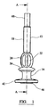
図1〜図4を参照すると、本発明の実施形態としてのガイド10が示されている。ガイド10は、ベース14に旋回可能に連結された本体12を有している。
[Detailed explanation]
1 to 4, a
本体12は、直線ガイド軸線を定めるようガイドの長手方向軸線に沿って延びる円形断面のチャネル16を有している。本体12は、全体として円筒形の形を有し、この本体は、回転対称である。本体12は、上方部分18および下方部分20を有している。上方部分18は、全体として直円柱の形状のものであり、下方部分20は、湾曲した形状のものである。使用の際に、握りを使用者に提供するよう下方部分20の表面には凹状部分が設けられている。本体12の近位端部は、内壁24に設けられたねじ山付き部分を有し、このねじ山付き部分は、使用の際に、器具26のねじ山付き部分と噛み合うことができる。
The
本体12の内面の遠位部分は、ステム30のねじ山付き部分を、噛み合い関係をなして受け入れる別のねじ山付き部分28を有している。
The distal portion of the inner surface of the
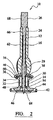
ベース14は、その長手方向軸線に関し全体として円形で対称の形状を有している。ベース14は、これにキャビティ32が設けられた全体として環状の構造を有する。ベース14の近位部分は、外壁36および内壁38により画定された実質的に環状のチャネル34を有している。ゴム製のOリング40が、チャネル34内に配置されている。
The
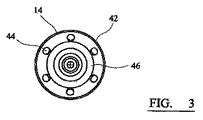
スカート42が、本体14から遠ざかって僅かに下方にベース14の遠位端部に向かって延びている。ガイド10を身体部分にしっかりと締結するよう取り付け具を受け入れる6つの等角度間隔を置いた複数の孔44が、スカート42に設けられている。
A
ベース14の最も遠位側の部分46は、ガイドを使用の際に身体部分に取り付けると、身体部分の表面に係合する継手となる。フーチング46は、ベースの長手方向中心軸線周りに延びる円形リムの形態をしている。フーチング46は、ベース14の長手方向軸線に垂直な平面を定める。ガイド軸線が旋回できる中心となる運動の中心は、以下により詳細に説明するように、その平面の中心のところに存在する。
The most
ベース14内に引っ込んだ状態で成形部48が設けられ、この成形部は、球の表面の一部に相当する外面を備えている。湾曲した成形部48は、ボールソケット形継手のソケット部となる。ガイド10は、ステム部30を更に有する。ステム30も又、全体として円筒形の形をしており、しかも全体として回転対称である。ねじ山付き部分50が、ステム30の近位端部のところに設けられている。断面が円形のチャネル52が、ステム30の長さに沿って延びている。成形部54が、ステム30の遠位端部のところに設けられている。成形部54は、全体として球の一部の形をした湾曲した外面を有している。図2に最も良く示されているように、ガイド10を組み立てると、ステム30は、湾曲成形部54がソケット48内に配置された状態で本体12に連結される。湾曲成形部54は、ボール部となり、したがって、成形部54,48は、本体12およびステム30が旋回できる中心となるボールソケット形継手を構成するようになっている。
A molded
要素56は、凹状ディスクの全体的形状を有し、この要素56の中には、中央開口部58が設けられている。要素56は、湾曲した下側支承面60を有している。支承面60は、球の一部の形を有し、中心が運動の中心に一致した曲率半径が、フーチング46の中心のところに位置している。内壁36、外壁38およびOリング40は、これらの間に、要素56が使用の際に動くことができるベース14の支承面を構成している。孔58周りの要素56の縁部は、ほぼ同じ形としてステム30の平坦な区分とねじ山付き部分50を有しており、要素56は、ステム30に対して回転することができないようになっている。
器具26は、長いシャフト62を備えた細長い器械の形状をしており、このシャフトは、その遠位端部のところに尖った先64を備えている。ねじ山付き部分66が、シャフト62の近位端部寄りに設けられている。ヘッド68が、器具26の遠位端部のところに設けられている。器具26は、本体12のチャネル16およびステム30のチャネル52内に受け入れ可能である。
The
ガイド10のコンポーネントは、チャネル16,52の中心に沿って通るガイド軸線がフーチング46の最も外側の平面の中心を通るように、しかも、ガイド軸線をその箇所回りに旋回させることができると共に、常時その箇所を通るように構成されている。支承面60の曲率により、本体12およびステム30の運動は、ガイド軸線がガイドの本体およびステムの旋回運動のための運動の中心であるこの箇所を常時通るように束縛される。それ故、空間中におけるガイド軸線の軌跡は、運動の中心のところに先端を備えた円錐である。
The components of the
使用にあたり、本体12をステム30から僅かにねじ戻すことにより、要素56を自由にし、ガイド軸線を要素56および成形部54,48により構成される部分ボールソケット形継手によって案内しながら運動の中心回りに旋回させることができる。ガイド軸線がベースに対して正確な向きにあるとき、本体12をステム30に対して回転させることにより、要素56は、外壁36、Oリング40および内壁38に押し付けられてベース14に対するガイド軸線の向きを固定する。
In use, the
器具26が、図1〜図3において、ガイドのガイドチャネル内に挿入された状態で示されているが、使用にあたり、器具26は、ガイド内に挿入される必要のないことは理解されよう。
Although the
次に、関節表面置換(“ASR”)手技におけるガイドの使用法につき図5、図6および図7を参照して説明する。しかしながら、理解されるように、ガイドの使用は、かかる外科手術手技には限定されず、身体部分に対するツール、器械または他の器具のガイド軸線またはガイド方向を定め、または求めるために任意の外科手術手技で使用できる。 Next, the use of the guide in the joint surface replacement (“ASR”) procedure will be described with reference to FIGS. 5, 6 and 7. However, as will be appreciated, the use of guides is not limited to such surgical procedures, and any surgical procedure for determining or determining the guide axis or direction of a tool, instrument or other instrument relative to a body part. Can be used in procedures.
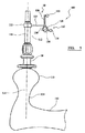
図5は、大腿骨112の大腿骨頭110に取り付けられたガイド10を示す略図100である。大腿骨頭110は、大腿骨頸部114により大腿骨112の近位部分に連結されている。大腿骨頸部は、図5の破線116によって示されているおおよその大腿骨頸部軸線を有している。破線118は、ガイド軸線を表している。
FIG. 5 is a schematic diagram 100 showing the
図5において、ガイド10は、マーカアレイ120(marker array 120)をこれに取り付けることによりコンピュータ支援外科手術(“CAS”)システムに用いられるよう構成されている。マーカアレイは、当該技術分野においてはスターとも呼ばれており、クランプ122および3本のアーム126,128,130を支持したステム124を有している。反射球132,134,136が、各アームの端っこ前の部分に取り付けられている。かかるマーカアレイは、反射された放射線、例えば赤外線を検出する追跡システム、例えば、独国のブレインラブ・ゲゼルシャフト・ミット・ベシュレンクテル・ハフツング(BrainLab GmbH)に提供されている、ベクトルビジョンシステム(vector vision system)に用いるのに適している。
In FIG. 5, guide 10 is configured for use in a computer assisted surgical ("CAS") system by attaching a
当業者には明らかな他の追跡技術を利用した他のマーカを利用することができ、例えば、超音波または他の音響マーカを用いることができる。さらに、既知の磁界分布を備えた磁界の変化を検出し、位置座標および角度の向きに関する情報を求めて、かかる情報を追跡システムに伝える磁気マーカを使用することができる。 Other markers utilizing other tracking techniques apparent to those skilled in the art can be utilized, for example, ultrasound or other acoustic markers can be used. In addition, magnetic markers can be used that detect magnetic field changes with known magnetic field distributions, determine information about position coordinates and angle orientation, and communicate such information to the tracking system.
用いられる追跡技術とは無関係に、追跡システムまたはCASシステムは、追跡対象のマーカを識別するのに十分な情報であらかじめプログラムされ、かかるシステムは、ガイドの長手方向軸線に対するマーカの位置および運動の中心からのガイドの位置を求める基礎となるデータを更に有する。それ故、使用にあたり、追跡システムは、マーカの現在の位置を監視し、この位置および向きに関する情報から、CASシステムは、追跡システムの基準系においてガイド軸線118の現在の位置を求めることができる。
Regardless of the tracking technique used, the tracking system or CAS system is pre-programmed with sufficient information to identify the marker to be tracked, such that the position of the marker relative to the longitudinal axis of the guide and the center of motion. Further comprising data on which to determine the position of the guide from Thus, in use, the tracking system monitors the current position of the marker, and from this position and orientation information, the CAS system can determine the current position of the
図6は、ガイド10を用いることができるCAS手技200の高レベル外観を提供するフローチャートである。ステップ202において、外科医は、手術部位にアクセスできるよう種々の切開部を作る。
FIG. 6 is a flow chart providing a high level appearance of a CAS procedure 200 that can use the
ステップ204において、患者の種々の身体部をCASシステムに登録して、追跡システムの基準系内における患者の骨の位置が分かるようにする。骨をCASシステムに登録する種々の技術を用いることができ、かかる技術は、一般に、当該技術分野において知られている。かかる一方法では、CASシステムは、骨の多くの包括的な仮想モデルを記憶装置に格納している。次に、外科医は、追跡可能なポインタを用いて幾つかの主要な解剖学的ランドマークを突き止めて、骨の全体的形状および寸法を求めることができるようにする。次に、システムは、かかるモデルのデータベースから、患者の実際の骨の寸法形状に1番良くマッチした包括的モデルのうちの1つを選択する。次に、外科医は、患者の実際の骨の相当広い表面領域にわたり広がる点から成る網、またはメッシュを集める。次に、追跡システムに由来するこの形状情報を用いて、包括的な骨モデルを変形させる(be morphed)と、患者の実際の骨の形状をより正確に表すことができる。このようにして、骨をCASシステムに登録する。変形実施形態では、ステップ202における手術部位の開放の前に、非侵襲的に登録手順を用いても良い。 In step 204, the various body parts of the patient are registered with the CAS system so that the position of the patient's bone in the reference system of the tracking system is known. Various techniques for registering bone with the CAS system can be used, and such techniques are generally known in the art. In one such method, the CAS system stores many comprehensive virtual models of bone in storage. The surgeon then uses a traceable pointer to locate several key anatomical landmarks so that the overall shape and dimensions of the bone can be determined. The system then selects from the database of such models one of the comprehensive models that best matches the patient's actual bone dimensions. The surgeon then collects a mesh, or mesh, of points that extend over a substantial surface area of the patient's actual bone. This shape information from the tracking system can then be used to more accurately represent the patient's actual bone shape when the comprehensive bone model is be morphed. In this way, the bone is registered with the CAS system. In an alternative embodiment, the registration procedure may be used non-invasively prior to opening the surgical site in step 202.
ステップ206において、外科医は、実施されるべき外科手術手技を計画するために計画立案ソフトウェアを用いても良い。この関節面置換例では、外科医の作業の流れにおけるステップのうちの1つは、穴を実施的に大腿骨頸部軸線に沿って開けることであり、この穴は、整形外科用大腿骨頭インプラントのステムを受け入れる。大腿骨頭インプラントの正確な配置は、置換用股関節の正確な機能発揮を保証するための、更に又、置換用股関節の摩耗を最小限に抑えると共に減少させるのを助けるために、重要である。計画立案ソフトウェアを用いて、ステップ206において、外科医は、大腿骨頭および寛骨臼カップインプラントの適正なサイズを選択し、更に、患者の大腿骨および骨盤に対するインプラントの適正な位置および向きを求めることができる。代表的には、かかる計画立案ソフトウェアは、例えばCT走査またはX線走査から先に捕捉された患者の骨盤および大腿骨の画像を用いて外科医が患者の骨の正確な表示を用いてインプラントの意図した位置および向きを計画できるようにする。計画立案は、図6では、術内ステップ206として示されているが、本発明の変形実施形態では、計画立案は、手術部位を開く前に、術前に実施することができる。計画立案は又、解剖学的データをどのようにして集めるかに応じて、患者を登録する前に実施できる。 In step 206, the surgeon may use planning software to plan the surgical procedure to be performed. In this articulating surface replacement example, one of the steps in the surgeon's workflow is to drill a hole along the femoral neck axis, which is the hole in the orthopedic femoral head implant. Accept the stem. Accurate placement of the femoral head implant is important to ensure the correct functioning of the replacement hip joint, and also to help minimize and reduce the wear of the replacement hip joint. Using the planning software, at step 206, the surgeon may select the proper size of the femoral head and acetabular cup implants and further determine the proper position and orientation of the implant relative to the patient's femur and pelvis. it can. Typically, such planning software can be used by the surgeon to use the patient's pelvis and femur images previously captured from a CT or X-ray scan to provide implant intent using an accurate representation of the patient's bone. To plan the position and orientation. Although planning is shown in FIG. 6 as intraoperative step 206, in an alternative embodiment of the present invention, planning can be performed preoperatively before opening the surgical site. Planning can also be performed before patient registration, depending on how the anatomical data is collected.
上述のことから理解されるように、図6に示すステップを実施する特定の順序は、必ずしも重要ではなく、種々のステップの順序は、様々であって良い。しかしながら、一般的に、外科医がCASを用いてガイドを配置することができる前に、外科医は、解剖学的データ、登録変換マトリックス(これは、患者の実際の位置と追跡システムの基準系との間の変換を数学的に定める)、軌道がどこにあるかの計画、軌道と大腿骨頭との間の計算された表面交点(これは、入口箇所を与える)にアクセスする必要がある。 As will be appreciated from the foregoing, the specific order in which the steps shown in FIG. 6 are performed is not necessarily important, and the order of the various steps may vary. In general, however, before the surgeon can place a guide using CAS, the surgeon will need to know the anatomical data, the registration transformation matrix (which is the actual location of the patient and the reference system of the tracking system). Need to access the plan of where the trajectory is, the calculated surface intersection between the trajectory and the femoral head (which gives the entry point).
次に、ステップ208において、種々の行為が外科医によって実施されて股関節置換術が実施されるようにする。CASシステムを用いて、この手技に用いられるインプラント、器械、ツールおよび他の器具が、これに取り付けられた追跡システムによって追跡可能なマーカを有することができ、したがって、インプラント、器械、ツールおよび器具の位置を、ディスプレイスクリーンを用いて、外科医により操縦されることができ、このディスプレイスクリーンは、患者の身体部分に対するインプラント、器械、ツールおよび器具の実際の現在の位置ならびに計画された位置および/または向きの視覚表示を提供することにより、外科医を案内する。 Next, in step 208, various actions are performed by the surgeon so that hip replacement is performed. With the CAS system, the implants, instruments, tools and other instruments used in this procedure can have markers that can be tracked by the tracking system attached to them, and thus the implants, instruments, tools and instruments The position can be steered by a surgeon using a display screen, which is the actual current position and the planned position and / or orientation of the implants, instruments, tools and instruments relative to the patient's body part. Guide the surgeon by providing a visual display of
股関節置換術については、本発明を不明瞭にしないように、本明細書では説明しない。しかしながら、本発明のガイド100を用いて実施できる種々のステップについて説明する。
Hip replacement is not described herein so as not to obscure the present invention. However, the various steps that can be performed using the
図7は、画像誘導外科手術(“IGS”)手技を容易にするディスプレイを提供するよう、CASシステムのデータ処理部により実施されるプロセス220を示すフローチャートである。ステップ222において、CASシステムは、外科医が穴を開けるようあらかじめ計画された計画軸線116を定める。ステップ224において、CASシステムは、計画立案ソフトウェアからこの情報にアクセスし、骨の現在の位置を追跡して外科医に意図した軸線116のリアルタイム表示を提供する。
FIG. 7 is a flowchart illustrating a process 220 performed by the data processing portion of the CAS system to provide a display that facilitates an image guided surgery (“IGS”) procedure. In step 222, the CAS system defines a
ガイド10の角度位置だけを変化させることができるので、ガイド10のベース14を、大腿骨頭の表面上に正確に配置して、その回転中心が骨の表面上の入口箇所と一致するようにすることが重要である。
Since only the angular position of the
ステップ226において、追跡システムは、マーカ120の位置を検出してこれを追跡し、CASシステムは、ガイド軸線118の位置の図形表示を生じさせ、これをディスプレイ上で外科医にリアルタイムで表示する。それ故、外科医は、ガイド軸線の視覚的表示および入口箇所の視覚的表示を骨中に用いて、大腿骨頭110の表面上におけるベース14の正確な配置を案内することができる。ガイドを大腿骨頭上にいったん正確に配置すると、スクリューまたは他の取り付け具を孔44内に導入して、ガイドベースを大腿骨頭にしっかりと固定してガイドベースが動かないようにする。外科医は、器具26をねじ戻し、次に、鋭利なタップを器具26のヘッド68に適用して、大腿骨頭110の表面に初期ガイドポールまたは刻み目を付けることにより、器具26を解除することができる。
In step 226, the tracking system detects and tracks the position of the
次に、外科医は、本体12を僅かにねじ戻して本体がベース14から僅かに弛んだ状態になるようにし、次に、外科医は、本体12を旋回させて、ガイド軸線118をIGSシステムのディスプレイユニットにより案内された意図した身体部分軸線116に整列させることができる。決定ボックス228およびプロセスフロー戻り線230で示されているように、CASシステムは、ガイド軸線118の位置を常時追跡し、その視覚的表示を表示し、この間、外科医は、ガイドを操作してこれを身体軸線に整列させる。ガイド軸線118と意図した身体部分軸線116が整列したことに外科医が満足すると、外科医は、本体12を回すことによりガイドを単に締め付ける。本体12を回転させることにより、ステム30が本体12内に引き込まれ、それにより、ステム30がベース14内に保持されると、圧縮力を要素56に及ぼす。それ故、本体12を回転させることにより、ガイドは、ベース14に対する固定された角度的向きで、本体12とロック関係をなす。次に、外科医は、ガイド10を用いて、ガイドチャネル16,52を介するパイロット穴の穿孔および人工大腿骨のステムを受け入れる別の穴の穿孔を案内することができる。
The surgeon then unscrews the
次に、図6に戻ると、ステップ210において、ガイドを取り外し、次に、外科手術手技を終了させる。次に、ステップ212において、外科医は、置換用股関節の性能に対する点検を行い、そして最終的に手術部位を閉じることができる。 Returning now to FIG. 6, at step 210, the guide is removed and the surgical procedure is then terminated. Next, at step 212, the surgeon can check for replacement hip performance and finally close the surgical site.
それ故、上述のガイドは、簡単な構造を有し、かかるガイドは、ガイドチャネルをベースに対して旋回させることしかできないので使用が容易であり、それにより、操作が容易になると共にコンポーネント部品の数および複雑さが減少する。 Therefore, the above-mentioned guide has a simple structure, and such a guide is easy to use because it can only pivot the guide channel relative to the base, thereby facilitating operation and component parts. Number and complexity are reduced.
ガイド10の部分を代表的には外科用ツールまたは器械の製造に用いられる任意の材料、例えばステンレス鋼または他の耐腐食合金から作られていても良い。一実施形態では、ガイドは、プラスチックで作られても良く、この場合、ガイドは、使い捨て器械として提供できる。
The portion of
〔実施の態様〕
(1)器具をガイド軸線に沿って案内するように、身体部分に取り付け可能な外科用のガイドにおいて、
前記ガイド軸線を定めていて、使用の際に前記器具を受け入れるチャネルを、有する本体と、
ベースであって、使用の際に前記身体部分に取り付けられると、前記身体部分の表面に係合し、前記ガイド軸線が前記身体部分に関する入口箇所を通っている状態で、前記身体部分に関する前記入口箇所上に前記本体を支持する、ベースと、
前記本体を前記ベースに取り付ける旋回機構体と、
を具備し、
前記本体は、旋回することによってのみ、かつ少なくとも2つの旋回自由度で、前記ベースに対して動くことができ、
前記ガイドは、前記入口箇所が前記本体の旋回の中心である運動の中心であるように構成されている、ガイド。
(2)実施態様(1)記載のガイドにおいて、
前記ガイドは、前記ベースに対する前記本体の前記角度位置を固定するように動作できるロックを更に備える、ガイド。
(3)実施態様(1)記載のガイドにおいて、
前記旋回機構体は、回転部分および静止部分により構成されるボールソケット形継手を含む、ガイド。
(4)実施態様(1)記載のガイドにおいて、
前記回転部分および前記静止部分は、前記回転部分と前記静止部分との間に、球の少なくとも一部である支承面、および前記支承面が動くことができる別の支承構造体を提供する、ガイド。
(5)実施態様(1)記載のガイドにおいて、
前記旋回機構体は、
球の表面の一部である第1の支承面を有する要素と、
前記第1の支承面が動くことができる第2の支承面と、
を含む、
前記第1の支承面の曲率半径は、前記第1の支承面と前記入口箇所との間に延びている、ガイド。
(6)実施態様(1)記載のガイドにおいて、
前記ベースは、前記ガイドを前記身体部分に固定するための複数個の取り付け箇所を有する、ガイド。
(7)実施態様(1)記載のガイドにおいて、
前記ガイドは、ステムを含み、
前記ステムは、前記本体に取り付けられると共に、前記ベース内に延びており、
前記ステムは、前記チャネルの延長部であって前記ガイド軸線と同一直線上に位置する、別のチャネルを含んでいる、ガイド。
(8)実施態様(2)記載のガイドにおいて、
前記ガイドは、ステムを含み、
前記ステムは、前記本体に取り付けられると共に、前記ベースによって保持された状態で、前記ベース内へ延びており、
前記本体および前記ステムは、前記ロックを構成するように協働する、ガイド。
(9)実施態様1ないし8のうちいずれか一に記載のガイドにおいて、
前記ガイドは、前記本体に取り付けられたマーカを更に含み、
前記マーカは、追跡システムによって追跡可能であり、これにより、前記追跡システムの座標系における前記ガイド軸線の位置を求めることができる、ガイド。
(10)実施態様(1)記載のガイドにおいて、
前記ガイドの各部分は、その長手方向軸線に関して回転対称である、ガイド。
Embodiment
(1) In a surgical guide attachable to a body part so as to guide the instrument along a guide axis,
A body defining a guide axis and having a channel for receiving the instrument in use;
The base, when attached to the body part in use, engages the surface of the body part and the entrance for the body part with the guide axis passing through the entrance location for the body part A base supporting the body on a location;
A turning mechanism for attaching the main body to the base;
Comprising
The body can move relative to the base only by pivoting and with at least two pivotal degrees of freedom;
The guide is configured such that the entrance location is the center of motion that is the center of rotation of the body.
(2) In the guide described in the embodiment (1),
The guide further comprises a lock operable to lock the angular position of the body relative to the base.
(3) In the guide described in the embodiment (1),
The swivel mechanism includes a ball and socket joint including a rotating part and a stationary part.
(4) In the guide described in the embodiment (1),
The rotating part and the stationary part provide a bearing surface that is at least part of a sphere between the rotating part and the stationary part, and another bearing structure on which the bearing surface can move. .
(5) In the guide described in the embodiment (1),
The swivel mechanism is
An element having a first bearing surface that is part of the surface of the sphere;
A second bearing surface on which the first bearing surface is movable;
including,
A guide, wherein a radius of curvature of the first bearing surface extends between the first bearing surface and the entrance location.
(6) In the guide described in the embodiment (1),
The base has a plurality of attachment points for fixing the guide to the body part.
(7) In the guide described in the embodiment (1),
The guide includes a stem;
The stem is attached to the body and extends into the base;
The stem includes another channel that is an extension of the channel and collinear with the guide axis.
(8) In the guide described in the embodiment (2),
The guide includes a stem;
The stem is attached to the main body and extends into the base while being held by the base.
The guide, wherein the body and the stem cooperate to form the lock.
(9) In the guide according to any one of
The guide further includes a marker attached to the body,
The guide is traceable by a tracking system, whereby the position of the guide axis in the coordinate system of the tracking system can be determined.
(10) In the guide described in the embodiment (1),
Each part of the guide is rotationally symmetric with respect to its longitudinal axis.
(11)差し向け軸線を求める方法であって、この差し向け軸線に沿って器具が身体部分の方へ差し向けられるようになっている、方法において、
ガイド器具を、前記身体部分の表面上の入口箇所上で前記身体部分に取り付けることであって、前記ガイドが、ベース、および前記器具をガイド軸線に沿って受け入れるチャネルを有する本体を有し、前記本体が、旋回によってのみ前記ベースに対して動くことができる、取り付けることと、
前記ガイドの前記本体を旋回させるだけで、前記ガイド軸線が前記差し向け軸線と実質的に一致するまで、前記ガイド軸線の向きを、前記入口箇所を通ったままの状態で変化させることと、
を含む、方法。
(11) A method for determining an orientation axis, wherein the instrument is directed toward the body part along the orientation axis,
Attaching a guide instrument to the body part on an entry point on a surface of the body part, the guide having a base and a body having a channel for receiving the instrument along a guide axis; Mounting the body can move relative to the base only by swiveling;
Merely turning the body of the guide, changing the orientation of the guide axis while passing through the entrance location until the guide axis substantially coincides with the pointing axis;
Including a method.
(12)差し向け軸線を求めるCAS方法であって、この差し向け軸線に沿って器具が身体部分の方へ差し向けられるようになっている、方法において、
前記差し向け軸線の向き、および、追跡システムの座標系における前記差し向け軸線を身体部分の表面上に通す入口箇所、を求めることと、
前記座標系においてガイドの位置を追跡することであって、前記ガイドが、ベース、および前記器具をガイド軸線に沿って受け入れるチャネルを有する本体を有し、前記本体が、旋回によってのみ前記ベースに対して動くことができる、追跡することと、
前記差し向け軸線に対する前記ガイド軸線の位置および/または前記入口箇所に対する前記ガイド軸線の位置を、図形で表示することと、
を含む、方法。
(12) A CAS method for determining a pointing axis, wherein an instrument is directed toward a body part along the pointing axis,
Determining the orientation of the pointing axis and the entry point through which the pointing axis in the coordinate system of the tracking system passes over the surface of the body part;
Tracking the position of a guide in the coordinate system, the guide having a base and a body having a channel for receiving the instrument along a guide axis, the body being relative to the base only by pivoting; Tracking,
Displaying the position of the guide axis with respect to the pointing axis and / or the position of the guide axis with respect to the entrance location in a graphic form;
Including a method.
(13)コンピュータプログラムコードにおいて、
実施態様(12)記載の方法を行うように、データ処理装置により実行可能である、コンピュータプログラムコード。
(13) In computer program code,
Computer program code executable by a data processing device to perform the method of embodiment (12).
(14)コンピュータプログラム製品において、
実施態様(13)記載のコンピュータプログラムコードが書き込まれた、コンピュータにより読み取り可能な媒体、
を具備する、コンピュータプログラム製品。
(14) In a computer program product,
A computer-readable medium in which the computer program code according to the embodiment (13) is written,
A computer program product comprising:
(15)外科用ガイドにおいて、
身体部分上に取り付け可能であり、本明細書に実質的に記述されたように器具をガイド軸線に沿って案内することができる、外科用ガイド。
(15) In the surgical guide,
A surgical guide that can be mounted on a body part and that can guide an instrument along a guide axis substantially as described herein.
(16)コンピュータにより実行される方法において、
本明細書に実質的に記述されたように器具を案内する、方法。
(16) In a method executed by a computer,
A method of guiding an instrument substantially as described herein.
Claims (16)
前記ガイド軸線を定めていて、使用の際に前記器具を受け入れるチャネルを、有する本体と、
ベースであって、使用の際に前記身体部分に取り付けられると、前記身体部分の表面に係合し、前記ガイド軸線が前記身体部分に関する入口箇所を通っている状態で、前記身体部分に関する前記入口箇所上に前記本体を支持する、ベースと、
前記本体を前記ベースに取り付ける旋回機構体と、
を具備し、
前記本体は、旋回することによってのみ、かつ少なくとも2つの旋回自由度で、前記ベースに対して動くことができ、
前記ガイドは、前記入口箇所が前記本体の旋回の中心である運動の中心であるように構成されている、ガイド。 In a surgical guide attachable to a body part so as to guide the instrument along a guide axis,
A body defining a guide axis and having a channel for receiving the instrument in use;
The base, when attached to the body part in use, engages the surface of the body part and the entrance for the body part with the guide axis passing through the entrance location for the body part A base supporting the body on a location;
A turning mechanism for attaching the main body to the base;
Comprising
The body can move relative to the base only by pivoting and with at least two pivotal degrees of freedom;
The guide is configured such that the entrance location is the center of motion that is the center of rotation of the body.
前記ガイドは、前記ベースに対する前記本体の前記角度位置を固定するように動作できるロックを更に備える、ガイド。 The guide of claim 1, wherein
The guide further comprises a lock operable to lock the angular position of the body relative to the base.
前記旋回機構体は、回転部分および静止部分により構成されるボールソケット形継手を含む、ガイド。 The guide of claim 1, wherein
The swivel mechanism includes a ball and socket joint including a rotating part and a stationary part.
前記回転部分および前記静止部分は、前記回転部分と前記静止部分との間に、球の少なくとも一部である支承面、および前記支承面が動くことができる別の支承構造体を提供する、ガイド。 The guide of claim 1, wherein
The rotating part and the stationary part provide a bearing surface that is at least part of a sphere between the rotating part and the stationary part, and another bearing structure on which the bearing surface can move. .
前記旋回機構体は、
球の表面の一部である第1の支承面を有する要素と、
前記第1の支承面が動くことができる第2の支承面と、
を含み、
前記第1の支承面の曲率半径は、前記第1の支承面と前記入口箇所との間に延びている、ガイド。 The guide of claim 1, wherein
The swivel mechanism is
An element having a first bearing surface that is part of the surface of the sphere;
A second bearing surface on which the first bearing surface is movable;
Including
A guide, wherein a radius of curvature of the first bearing surface extends between the first bearing surface and the entrance location.
前記ベースは、前記ガイドを前記身体部分に固定するための複数個の取り付け箇所を有する、ガイド。 The guide of claim 1, wherein
The base has a plurality of attachment points for fixing the guide to the body part.
前記ガイドは、ステムを含み、
前記ステムは、前記本体に取り付けられると共に、前記ベース内に延びており、
前記ステムは、前記チャネルの延長部であって前記ガイド軸線と同一直線上に位置する、別のチャネルを含んでいる、ガイド。 The guide of claim 1, wherein
The guide includes a stem;
The stem is attached to the body and extends into the base;
The stem includes another channel that is an extension of the channel and collinear with the guide axis.
前記ガイドは、ステムを含み、
前記ステムは、前記本体に取り付けられると共に、前記ベースによって保持された状態で、前記ベース内へ延びており、
前記本体および前記ステムは、前記ロックを構成するように協働する、ガイド。 The guide according to claim 2,
The guide includes a stem;
The stem is attached to the main body and extends into the base while being held by the base.
The guide, wherein the body and the stem cooperate to form the lock.
前記ガイドは、前記本体に取り付けられたマーカを更に含み、
前記マーカは、追跡システムによって追跡可能であり、これにより、前記追跡システムの座標系における前記ガイド軸線の位置を求めることができる、ガイド。 The guide according to any one of claims 1 to 8,
The guide further includes a marker attached to the body,
The guide is traceable by a tracking system, whereby the position of the guide axis in the coordinate system of the tracking system can be determined.
前記ガイドの各部分は、その長手方向軸線に関して回転対称である、ガイド。 The guide of claim 1, wherein
Each part of the guide is rotationally symmetric with respect to its longitudinal axis.
ガイド器具を、前記身体部分の表面上の入口箇所上で前記身体部分に取り付けることであって、前記ガイドが、ベース、および前記器具をガイド軸線に沿って受け入れるチャネルを有する本体を有し、前記本体が、旋回によってのみ前記ベースに対して動くことができる、取り付けることと、
前記ガイドの前記本体を旋回させるだけで、前記ガイド軸線が前記差し向け軸線と実質的に一致するまで、前記ガイド軸線の向きを、前記入口箇所を通ったままの状態で変化させることと、
を含む、方法。 A method for determining an orientation axis, wherein the device is directed toward a body part along the orientation axis,
Attaching a guide instrument to the body part on an entry point on a surface of the body part, the guide having a base and a body having a channel for receiving the instrument along a guide axis; Mounting the body can move relative to the base only by swiveling;
Merely turning the body of the guide, changing the orientation of the guide axis while passing through the entrance location until the guide axis substantially coincides with the pointing axis;
Including a method.
前記差し向け軸線の向き、および、追跡システムの座標系における前記差し向け軸線を身体部分の表面上に通す入口箇所、を求めることと、
前記座標系においてガイドの位置を追跡することであって、前記ガイドが、ベース、および前記器具をガイド軸線に沿って受け入れるチャネルを有する本体を有し、前記本体が、旋回によってのみ前記ベースに対して動くことができる、追跡することと、
前記差し向け軸線に対する前記ガイド軸線の位置および/または前記入口箇所に対する前記ガイド軸線の位置を、図形で表示することと、
を含む、方法。 A CAS method for determining an orientation axis, wherein an instrument is directed toward a body part along the orientation axis.
Determining the orientation of the pointing axis and the entry point through which the pointing axis in the coordinate system of the tracking system passes over the surface of the body part;
Tracking the position of a guide in the coordinate system, the guide having a base and a body having a channel for receiving the instrument along a guide axis, the body being relative to the base only by pivoting; Tracking,
Displaying the position of the guide axis with respect to the pointing axis and / or the position of the guide axis with respect to the entrance location in a graphic form;
Including a method.
請求項12記載の方法を行うように、データ処理装置により実行可能である、コンピュータプログラムコード。 In computer program code,
Computer program code executable by a data processing device to perform the method of claim 12.
請求項13記載のコンピュータプログラムコードが書き込まれた、コンピュータにより読み取り可能な媒体、
を具備する、コンピュータプログラム製品。 In computer program products,
A computer readable medium having the computer program code of claim 13 written thereon,
A computer program product comprising:
身体部分上に取り付け可能であり、特許請求の範囲に実質的に記述されたように器具をガイド軸線に沿って案内することができる、外科用ガイド。 In the surgical guide,
A surgical guide that is mountable on a body part and that can guide an instrument along a guide axis as substantially described in the claims.
特許請求の範囲に実質的に記述されたように器具を案内する、方法。 In a method executed by a computer,
A method of guiding an instrument substantially as described in the claims.
Applications Claiming Priority (2)
| Application Number | Priority Date | Filing Date | Title |
|---|---|---|---|
| GBGB0505782.3A GB0505782D0 (en) | 2005-03-22 | 2005-03-22 | Surgical guide |
| PCT/GB2006/001006 WO2006100458A2 (en) | 2005-03-22 | 2006-03-21 | Surgical guide |
Publications (2)
| Publication Number | Publication Date |
|---|---|
| JP2008534040A true JP2008534040A (en) | 2008-08-28 |
| JP2008534040A5 JP2008534040A5 (en) | 2009-05-07 |
Family
ID=34531604
Family Applications (1)
| Application Number | Title | Priority Date | Filing Date |
|---|---|---|---|
| JP2008502461A Pending JP2008534040A (en) | 2005-03-22 | 2006-03-21 | Surgical guide |
Country Status (5)
| Country | Link |
|---|---|
| US (1) | US20080228188A1 (en) |
| EP (1) | EP1879511A2 (en) |
| JP (1) | JP2008534040A (en) |
| GB (1) | GB0505782D0 (en) |
| WO (1) | WO2006100458A2 (en) |
Cited By (2)
| Publication number | Priority date | Publication date | Assignee | Title |
|---|---|---|---|---|
| WO2012169642A1 (en) * | 2011-06-06 | 2012-12-13 | 株式会社大野興業 | Method for manufacturing registration template |
| JP2017530842A (en) * | 2014-09-09 | 2017-10-19 | デピュイ・シンセス・プロダクツ・インコーポレイテッド | Securing the proximal end of the minimally invasive working channel |
Families Citing this family (14)
| Publication number | Priority date | Publication date | Assignee | Title |
|---|---|---|---|---|
| US20080109085A1 (en) * | 2006-11-03 | 2008-05-08 | Howmedica Osteonics Corp. | Method and apparatus for hip femoral resurfacing tooling |
| DE102008052680A1 (en) | 2008-10-22 | 2010-04-29 | Surgitaix Ag | Device for the controlled adjustment of a surgical positioning unit |
| WO2010063117A1 (en) * | 2008-12-02 | 2010-06-10 | Andre Novomir Hladio | Method and system for aligning a prosthesis during surgery using active sensors |
| US8366719B2 (en) | 2009-03-18 | 2013-02-05 | Integrated Spinal Concepts, Inc. | Image-guided minimal-step placement of screw into bone |
| US9168106B2 (en) * | 2009-05-05 | 2015-10-27 | Blue Ortho | Device and method for instrument adjustment in computer assisted surgery |
| ATE537749T1 (en) * | 2009-06-03 | 2012-01-15 | Brainlab Ag | EXPRESS REGISTRATION OF BODY REGIONS |
| EP2258283B1 (en) * | 2009-06-05 | 2013-08-28 | BrainLAB AG | Tool attachment for medical applications |
| EP2632382B1 (en) * | 2010-10-28 | 2017-09-20 | Fiagon AG Medical Technologies | Navigating attachment for optical devices in medicine, and method |
| US20120123252A1 (en) * | 2010-11-16 | 2012-05-17 | Zebris Medical Gmbh | Imaging apparatus for large area imaging of a body portion |
| EP2651344A4 (en) | 2010-12-17 | 2015-08-19 | Intellijoint Surgical Inc | Method and system for aligning a prosthesis during surgery |
| US9314188B2 (en) | 2012-04-12 | 2016-04-19 | Intellijoint Surgical Inc. | Computer-assisted joint replacement surgery and navigation systems |
| US9247998B2 (en) | 2013-03-15 | 2016-02-02 | Intellijoint Surgical Inc. | System and method for intra-operative leg position measurement |
| DE102013222230A1 (en) | 2013-10-31 | 2015-04-30 | Fiagon Gmbh | Surgical instrument |
| EP3719749A1 (en) | 2019-04-03 | 2020-10-07 | Fiagon AG Medical Technologies | Registration method and setup |
Citations (3)
| Publication number | Priority date | Publication date | Assignee | Title |
|---|---|---|---|---|
| JP2001517530A (en) * | 1997-09-16 | 2001-10-09 | エレクタ・イ・ジェ・エス・ソシエテ・アノニム | Apparatus and method for setting stereotactically and endoscopically positioned appliances |
| JP2002502276A (en) * | 1997-05-15 | 2002-01-22 | リージェンツ オブ ザ ユニバーシティ オブ ミネソタ | Trajectory guide for surgical instruments |
| WO2004021898A1 (en) * | 2002-09-05 | 2004-03-18 | Radi Medical Systems Ab | Guide for a medical device |
Family Cites Families (40)
| Publication number | Priority date | Publication date | Assignee | Title |
|---|---|---|---|---|
| US86016A (en) * | 1869-01-19 | Silas j | ||
| US1717061A (en) * | 1927-11-14 | 1929-06-11 | Nunes Roland | Newspaper-clipping cutter |
| US2181746A (en) * | 1939-02-04 | 1939-11-28 | John R Siebrandt | Combination bone clamp and adjustable drill guide |
| US2416228A (en) * | 1944-08-15 | 1947-02-18 | Gudel & Sheppard Co | Cutting tool |
| US3627334A (en) * | 1969-03-13 | 1971-12-14 | Robert R Reddy | Fluid-sealing washer and joint assembly |
| DE2834295B2 (en) * | 1978-08-04 | 1980-05-29 | Orthoplant Orthopaedische Implantate Gmbh & Co Kg, 2800 Bremen | Device for producing a lateral surface that tapers conically from the frontal end section of a bone |
| JPS5954192U (en) * | 1982-08-25 | 1984-04-09 | 久保 徹志 | Holder for welding pipes, etc. |
| US4522201A (en) * | 1983-04-14 | 1985-06-11 | Tongue John R | Orthopedic surgery drill guide apparatus |
| US4752296A (en) * | 1983-05-06 | 1988-06-21 | Buechel Frederick F | Prosthesis with interlocking fixation and providing reduction of stress shielding |
| US4896663A (en) * | 1988-10-14 | 1990-01-30 | Boehringer Mannheim Corporation | Self centering femoral drill jig |
| US4976740A (en) * | 1989-07-14 | 1990-12-11 | Kleiner Jeffrey B | Anchored femoral dome |
| US5019039A (en) * | 1989-11-15 | 1991-05-28 | Anderson Ronald W | Fluid drainage needle method of use |
| US5312409A (en) * | 1992-06-01 | 1994-05-17 | Mclaughlin Robert E | Drill alignment guide |
| US5597379A (en) * | 1994-09-02 | 1997-01-28 | Hudson Surgical Design, Inc. | Method and apparatus for femoral resection alignment |
| SE9501829D0 (en) * | 1995-05-17 | 1995-05-17 | Astra Ab | Drill guide |
| US5569262A (en) * | 1995-05-19 | 1996-10-29 | Carney; William P. | Guide tool for surgical devices |
| NL1005234C2 (en) * | 1997-02-10 | 1998-08-11 | Novarticulate Bv | Hip replacement and a method of placing such a hip replacement. |
| US6022357A (en) * | 1997-03-03 | 2000-02-08 | Aesculap Ag & Co. Kg | Surgical instrument |
| US5830215A (en) * | 1997-06-06 | 1998-11-03 | Incavo; Stephen J. | Removal apparatus and method |
| US6036696A (en) * | 1997-12-19 | 2000-03-14 | Stryker Technologies Corporation | Guide-pin placement device and method of use |
| US5997582A (en) * | 1998-05-01 | 1999-12-07 | Weiss; James M. | Hip replacement methods and apparatus |
| US6156069A (en) * | 1999-02-04 | 2000-12-05 | Amstutz; Harlan C. | Precision hip joint replacement method |
| US6258097B1 (en) * | 2000-06-02 | 2001-07-10 | Bristol-Myers Squibb Co | Head center instrument and method of using the same |
| DE10029737B4 (en) * | 2000-06-23 | 2006-01-19 | Mri Devices Daum Gmbh | Navigation of a medical instrument |
| US6893447B2 (en) * | 2000-09-24 | 2005-05-17 | Medtronic, Inc. | Surgical reference frame fixation device with cannulated post and method of use |
| DE50110247D1 (en) * | 2001-04-27 | 2006-08-03 | Zimmer Gmbh | Drill lower for fixing the axis of a femoral head prosthesis |
| US20030055436A1 (en) * | 2001-09-14 | 2003-03-20 | Wolfgang Daum | Navigation of a medical instrument |
| US7527631B2 (en) * | 2003-03-31 | 2009-05-05 | Depuy Products, Inc. | Arthroplasty sizing gauge |
| GB2401550B (en) * | 2003-05-12 | 2005-04-20 | Corin Ltd | Head centering jig for femoral resurfacing |
| GB0313445D0 (en) * | 2003-06-11 | 2003-07-16 | Midland Medical Technologies L | Hip resurfacing |
| GB0322084D0 (en) * | 2003-09-22 | 2003-10-22 | Depuy Int Ltd | A drill guide assembly |
| BRPI0416213B8 (en) * | 2003-11-20 | 2021-06-22 | Microport Orthopedics Holdings Inc | guide loop for guiding the placement of the guidewire in the femur |
| AU2004296595B2 (en) * | 2003-12-12 | 2010-07-08 | Chana, Gursharan Singh | Improved targeting device |
| US7879042B2 (en) * | 2004-03-05 | 2011-02-01 | Depuy Products, Inc. | Surface replacement extractor device and associated method |
| ATE371410T1 (en) * | 2004-04-20 | 2007-09-15 | Finsbury Dev Ltd | ALIGNMENT GUIDANCE |
| GB0420347D0 (en) * | 2004-09-13 | 2004-10-13 | Finsbury Dev Ltd | Tool |
| GB0601803D0 (en) * | 2006-01-30 | 2006-03-08 | Finsbury Dev Ltd | Tool |
| EP2049867A1 (en) * | 2006-08-03 | 2009-04-22 | Orthosoft, Inc. | Computer-assisted surgery tools and system |
| GB0703691D0 (en) * | 2007-02-26 | 2007-04-04 | Benoist Girard Sas | Apparatus for Preparing A Prosthetic Stem Cavity in A Femur |
| JP5523308B2 (en) * | 2007-05-14 | 2014-06-18 | クィーンズ ユニバーシティー アット キングストン | Patient-specific surgical guidance tools and methods of use |
-
2005
- 2005-03-22 GB GBGB0505782.3A patent/GB0505782D0/en not_active Ceased
-
2006
- 2006-03-21 JP JP2008502461A patent/JP2008534040A/en active Pending
- 2006-03-21 WO PCT/GB2006/001006 patent/WO2006100458A2/en not_active Application Discontinuation
- 2006-03-21 EP EP06726442A patent/EP1879511A2/en not_active Withdrawn
-
2007
- 2007-09-21 US US11/859,489 patent/US20080228188A1/en not_active Abandoned
Patent Citations (3)
| Publication number | Priority date | Publication date | Assignee | Title |
|---|---|---|---|---|
| JP2002502276A (en) * | 1997-05-15 | 2002-01-22 | リージェンツ オブ ザ ユニバーシティ オブ ミネソタ | Trajectory guide for surgical instruments |
| JP2001517530A (en) * | 1997-09-16 | 2001-10-09 | エレクタ・イ・ジェ・エス・ソシエテ・アノニム | Apparatus and method for setting stereotactically and endoscopically positioned appliances |
| WO2004021898A1 (en) * | 2002-09-05 | 2004-03-18 | Radi Medical Systems Ab | Guide for a medical device |
Cited By (3)
| Publication number | Priority date | Publication date | Assignee | Title |
|---|---|---|---|---|
| WO2012169642A1 (en) * | 2011-06-06 | 2012-12-13 | 株式会社大野興業 | Method for manufacturing registration template |
| JPWO2012169642A1 (en) * | 2011-06-06 | 2015-02-23 | 希 松本 | Registration template manufacturing method |
| JP2017530842A (en) * | 2014-09-09 | 2017-10-19 | デピュイ・シンセス・プロダクツ・インコーポレイテッド | Securing the proximal end of the minimally invasive working channel |
Also Published As
| Publication number | Publication date |
|---|---|
| WO2006100458A3 (en) | 2007-01-25 |
| EP1879511A2 (en) | 2008-01-23 |
| GB0505782D0 (en) | 2005-04-27 |
| WO2006100458A2 (en) | 2006-09-28 |
| US20080228188A1 (en) | 2008-09-18 |
Similar Documents
| Publication | Publication Date | Title |
|---|---|---|
| JP2008534040A (en) | Surgical guide | |
| US5984930A (en) | Biopsy guide | |
| US8206405B2 (en) | Acetabular cup positioning | |
| US8123754B2 (en) | Surgical jig | |
| US8709016B2 (en) | Surgical guide system using an active robot arm | |
| EP1430841B1 (en) | Surgical instrument | |
| USRE42226E1 (en) | Percutaneous registration apparatus and method for use in computer-assisted surgical navigation | |
| US7452357B2 (en) | System and method for planning treatment of tissue | |
| AU2003270992B2 (en) | Surgical instrument and positioning method | |
| JP6093371B2 (en) | Methods and devices for computer-assisted surgery | |
| US7833221B2 (en) | System and method for treatment of tissue using the tissue as a fiducial | |
| JP4398732B2 (en) | Non-imaging computer-aided navigation system for hip replacement surgery | |
| EP1649818B1 (en) | Surgical device guide for use with an imaging system | |
| JP2005246059A (en) | Surgical instrument for use in computer assisted navigation system | |
| JP2004237092A (en) | Surgical instrument | |
| EP2249748B1 (en) | Acetabular alignment guide | |
| CA3016785C (en) | Tracked suction tool | |
| US20230087163A1 (en) | Technique For Providing User Guidance In Surgical Navigation | |
| WO2006030637A1 (en) | Bone tracing device securing member | |
| Zheng et al. | Technical principles of computer assisted orthopaedic surgery |
Legal Events
| Date | Code | Title | Description |
|---|---|---|---|
| RD04 | Notification of resignation of power of attorney |
Free format text: JAPANESE INTERMEDIATE CODE: A7424 Effective date: 20081110 |
|
| A521 | Written amendment |
Free format text: JAPANESE INTERMEDIATE CODE: A523 Effective date: 20090317 |
|
| A621 | Written request for application examination |
Free format text: JAPANESE INTERMEDIATE CODE: A621 Effective date: 20090317 |
|
| A977 | Report on retrieval |
Free format text: JAPANESE INTERMEDIATE CODE: A971007 Effective date: 20110715 |
|
| A131 | Notification of reasons for refusal |
Free format text: JAPANESE INTERMEDIATE CODE: A131 Effective date: 20110802 |
|
| A601 | Written request for extension of time |
Free format text: JAPANESE INTERMEDIATE CODE: A601 Effective date: 20111102 |
|
| A602 | Written permission of extension of time |
Free format text: JAPANESE INTERMEDIATE CODE: A602 Effective date: 20111110 |
|
| A521 | Written amendment |
Free format text: JAPANESE INTERMEDIATE CODE: A523 Effective date: 20111124 |
|
| A02 | Decision of refusal |
Free format text: JAPANESE INTERMEDIATE CODE: A02 Effective date: 20120110 |