JP2008529410A - System and method for performing wireless routing - Google Patents
System and method for performing wireless routing Download PDFInfo
- Publication number
- JP2008529410A JP2008529410A JP2007553108A JP2007553108A JP2008529410A JP 2008529410 A JP2008529410 A JP 2008529410A JP 2007553108 A JP2007553108 A JP 2007553108A JP 2007553108 A JP2007553108 A JP 2007553108A JP 2008529410 A JP2008529410 A JP 2008529410A
- Authority
- JP
- Japan
- Prior art keywords
- communication
- base station
- node
- actual
- quality metric
- Prior art date
- Legal status (The legal status is an assumption and is not a legal conclusion. Google has not performed a legal analysis and makes no representation as to the accuracy of the status listed.)
- Pending
Links
Images


Classifications
-
- H—ELECTRICITY
- H04—ELECTRIC COMMUNICATION TECHNIQUE
- H04W—WIRELESS COMMUNICATION NETWORKS
- H04W40/00—Communication routing or communication path finding
- H04W40/24—Connectivity information management, e.g. connectivity discovery or connectivity update
- H04W40/248—Connectivity information update
-
- H—ELECTRICITY
- H04—ELECTRIC COMMUNICATION TECHNIQUE
- H04L—TRANSMISSION OF DIGITAL INFORMATION, e.g. TELEGRAPHIC COMMUNICATION
- H04L45/00—Routing or path finding of packets in data switching networks
- H04L45/02—Topology update or discovery
- H04L45/028—Dynamic adaptation of the update intervals, e.g. event-triggered updates
-
- H—ELECTRICITY
- H04—ELECTRIC COMMUNICATION TECHNIQUE
- H04L—TRANSMISSION OF DIGITAL INFORMATION, e.g. TELEGRAPHIC COMMUNICATION
- H04L45/00—Routing or path finding of packets in data switching networks
- H04L45/12—Shortest path evaluation
- H04L45/124—Shortest path evaluation using a combination of metrics
Abstract
無線通信の方法およびシステム。無線システムの性能を測定するための測定基準が、生成され、本システムの理想化されたシミュレーションを用いて生成された測定基準と比較される。実際のシステム性能が所定のレベルより下にある場合、本システムは、そのような構成についての中央に集中され、または分散された方法を使用して性能を改善するように再構成することができる。 Wireless communication method and system. A metric for measuring the performance of the wireless system is generated and compared to the metric generated using an idealized simulation of the system. If the actual system performance is below a predetermined level, the system can be reconfigured to improve performance using a centralized or distributed method for such a configuration. .
Description
本発明は、無線通信の分野に関する。より詳細には、本発明は、無線デバイス間の通信経路を構成する方法に関する。 The present invention relates to the field of wireless communications. More particularly, the present invention relates to a method for configuring a communication path between wireless devices.
無線通信システムは、経路指定プロトコルを使用して、第1のデバイスから第2のデバイスに情報を移動させる。そのようなシステムでは、しばしば、無線通信システムを第2の通信システムに接続する1つまたは複数の基地局(ルートノードまたはゲートウェイを含めて様々な用語が使用される)が存在する。1つの例は、無線システムと有線システムとの間の仲介手段としての役割を果たすアクセスポイントである。無線システム中の他のデバイスは、どのようにしてデータを経路指定して、ベースノードに到達するかを決定する必要がある。 The wireless communication system moves information from the first device to the second device using a routing protocol. In such systems, there is often one or more base stations (a variety of terms are used including root nodes or gateways) that connect a wireless communication system to a second communication system. One example is an access point that serves as an intermediary between a wireless system and a wired system. Other devices in the wireless system need to determine how to route the data to reach the base node.
デバイスの信頼可能な伝送距離が、ベースノードを含んでいないこともあるので、経路指定を行う戦略は、多くの場合に、中間のデバイスを使用することになる。例えば、図1に示されるように、デバイスXは、通信距離RXを有し、デバイスYは、通信距離RYを有し、ベースデバイスBは、通信距離RBを有する。これらの3つのデバイスだけが無線ネットワーク中に含まれる場合には、ソリューションは単純である。すなわちXがBに対して送信するデータを有するときに、Xは、Yに対してそのデータを送信することになり、YはBに対してそのデータを送信することになる。しかし、より多くのデバイスが追加されるにつれて、経路指定を行うソリューションは、より複雑になる。 Since the device's reliable transmission distance may not include the base node, routing strategies often use intermediate devices. For example, as shown in FIG. 1, device X has a communication distance RX, device Y has a communication distance RY, and base device B has a communication distance RB. If only these three devices are included in the wireless network, the solution is simple. That is, when X has data to send to B, X will send that data to Y, and Y will send that data to B. However, as more devices are added, the routing solution becomes more complex.
例示の実施形態においては、本発明は、1つの基地局といくつかのノードデバイスとを含む無線通信システムの性能を解析する方法を含み、本方法は、システム中のデバイス対のリンク特性を観察するステップと、そのリンク特性を使用して、中央に集中された通信ソリューションを生成するステップと、中央に集中された通信ソリューションを使用して、第1の品質測定基準を計算するステップと、それらのノードデバイスについての実際の通信構成を観察し第2の品質測定基準を生成するステップと、第1の品質測定基準を第2の品質測定基準と比較するステップとを含む。 In an exemplary embodiment, the present invention includes a method for analyzing the performance of a wireless communication system that includes a base station and a number of node devices, the method observing link characteristics of device pairs in the system. Generating a centralized communication solution using the link characteristics; calculating a first quality metric using the centralized communication solution; and Observing an actual communication configuration for the first node device to generate a second quality metric, and comparing the first quality metric to the second quality metric.
別の実施形態においては、中央に集中された通信ソリューションは、ノードデバイスごとに基地局に対する第1および第2の(またはより多くの)オーバーラップしない通信経路が定義されることを特徴としている。別の例示の実施形態では、実際の通信構成はまた、ノードデバイスごとに基地局に対する第1および第2の(またはより多くの)オーバーラップしない通信経路を定義し、少なくとも一部の定義された通信経路は、ノードデバイスと基地局との間の中間ノードを含んでいる。第1および第2の品質測定基準は、少なくとも一部の定義された通信経路中の各中間ノードによって導入される待ち時間の和に関連する成分を含むことができる。 In another embodiment, the centralized communication solution is characterized in that first and second (or more) non-overlapping communication paths to the base station are defined for each node device. In another exemplary embodiment, the actual communication configuration also defines first and second (or more) non-overlapping communication paths to the base station for each node device, and at least some defined The communication path includes intermediate nodes between the node device and the base station. The first and second quality metrics may include a component related to a sum of latency introduced by each intermediate node in at least some defined communication paths.
さらに別の実施形態においては、第1および第2の品質測定基準は、第1のノードデバイスと基地局との間のホップ数に関連する成分を含んでいる。また、第1および第2の品質測定基準は、第1のノードデバイスと基地局との間で定義された経路中で使用されるリンクのリンク品質に関連する成分を含むことができる。別の例示の実施形態においては、中央に集中された通信ソリューションと実際の通信構成は、通信が第1のノードデバイスと基地局との間で通過する中間ノードを有する通信経路を定義し、ここで第1および第2の品質測定基準は、中間ノードで現れるオーバーラップする経路の数に関連する成分を含んでいる。本方法はまた、比較するステップが、あらかじめ定義されたレベルを超えるシステムの非効率性を示す場合、システムを再構成するステップを含むこともある。 In yet another embodiment, the first and second quality metrics include a component related to the number of hops between the first node device and the base station. The first and second quality metrics may also include components related to the link quality of the links used in the path defined between the first node device and the base station. In another exemplary embodiment, the centralized communication solution and the actual communication configuration define a communication path having intermediate nodes through which communication passes between the first node device and the base station, where The first and second quality metrics include components related to the number of overlapping paths that appear at intermediate nodes. The method may also include reconfiguring the system if the comparing step indicates system inefficiency beyond a predefined level.
別の例示の実施形態は、少なくとも1つの基地局と、互いに無線通信を行うように構成された、いくつかのノードデバイスとを備える無線通信システムを含み、本システム中の、あるいは本システムに通信を行うように結合された少なくとも1つの解析するデバイスは、本システム中で定義される実際の通信経路に関連するデータを収集し、システム通信ステータスの実際の品質測定基準を観察するように構成され、解析するデバイスは、さらに実際の品質測定基準と比較するための数学的に最適な品質測定基準を生成するように構成される。 Another exemplary embodiment includes a wireless communication system comprising at least one base station and a number of node devices configured to wirelessly communicate with each other, communicating in or to the system. The at least one analyzing device coupled to perform is configured to collect data relating to actual communication paths defined in the system and to observe actual quality metrics of system communication status. The analyzing device is further configured to generate a mathematically optimal quality metric for comparison with the actual quality metric.
別の実施形態においては、ノードデバイスごとに基地局に対する第1および第2のオーバーラップしない通信経路は、数学的に最適な品質測定基準が生成されるときに定義される。さらに別の実施形態においては、実際の通信構成は、ノードデバイスごとに基地局に対する第1および第2のオーバーラップしない通信経路を定義し、少なくとも一部の定義される通信経路は、ノードデバイスと基地局との間の中間ノードを含んでいる。また、実際の最適な品質測定基準は、少なくとも一部の定義される通信経路中の各中間ノードによって導入される待ち時間の和に関連する成分を含むことができる。 In another embodiment, the first and second non-overlapping communication paths for the base station for each node device are defined when a mathematically optimal quality metric is generated. In yet another embodiment, the actual communication configuration defines first and second non-overlapping communication paths for the base station for each node device, and at least some of the defined communication paths are between the node device and Includes intermediate nodes to and from the base station. Also, the actual optimal quality metric can include a component related to the sum of the latency introduced by each intermediate node in at least some defined communication paths.
別の実施形態においては、実際の最適な品質測定基準は、第1のノードデバイスと基地局との間のホップ数に関連する成分を含んでいる。さらに別の実施形態においては、実際の最適な品質測定基準は、第1のノードデバイスと基地局との間で定義される経路中で使用されるリンクのリンク品質に関連する成分を含んでいる。また、いくつかの最適な通信経路は、数学的に最適な測定基準が生成されるときに定義することができ、少なくとも1つの最適な通信経路は、第1のノードから基地局へとデータを搬送する中間ノードを有し、少なくとも1つの実際の通信経路は、中間ノードを含むことができ、実際の最適な品質測定基準は、中間ノードで現れるオーバーラップする経路の数に関連する成分を含むことができる。さらに別の実施形態においては、本システムは、本システムを介して基地局に対してデータを経路指定するための第1の経路指定プロトコルを有するように構成され、数学的に最適な測定基準の、実際の測定基準との比較が、所定のレベルを超えるシステムの非効率性を示す場合に、新しい経路指定プロトコルが、第1の経路指定プロトコルを置き換えるように生成される。 In another embodiment, the actual optimal quality metric includes a component related to the number of hops between the first node device and the base station. In yet another embodiment, the actual optimal quality metric includes a component related to the link quality of the link used in the path defined between the first node device and the base station. . Also, some optimal communication paths can be defined when a mathematically optimal metric is generated, and at least one optimal communication path transfers data from the first node to the base station. Having at least one intermediate communication node, at least one actual communication path can include an intermediate node, and an actual optimal quality metric includes a component related to the number of overlapping paths that appear at the intermediate node be able to. In yet another embodiment, the system is configured to have a first routing protocol for routing data through the system to a base station, with a mathematically optimal metric. A new routing protocol is generated to replace the first routing protocol if the comparison with the actual metric indicates system inefficiency above a predetermined level.
例示の一実施形態においては、本発明は、少なくとも1つの基地局と、互いに無線通信を行うように構成された、いくつかのインフラストラクチャノードデバイスと、インフラストラクチャノードデバイスと通信を行ういくつかのリーフデバイスとを備える無線通信システムを含み、本システム中の、または本システムに通信を行うように結合された少なくとも1つの解析するデバイスは、本システム中で定義される実際の通信経路に関連するデータを収集し、システム通信ステータスの実際の品質測定基準を観察するように構成され、解析するデバイスは、さらに実際の品質測定基準と比較するための数学的に最適な品質測定基準を生成するように構成される。 In an exemplary embodiment, the present invention provides a number of infrastructure node devices configured to communicate with each other wirelessly with at least one base station and a number of communicating with the infrastructure node devices. At least one analyzing device in or coupled to communicate with the system, including a wireless communication system comprising a leaf device, is associated with an actual communication path defined in the system The device that is configured to collect data and observe the actual quality metric of system communication status to generate a mathematically optimal quality metric for further comparison with the actual quality metric Configured.
さらに別の実施形態においては、リーフデバイスは、スリープモードとアクティブモードを有するセンサを備え、それらのセンサは、スケジュールされた時刻に覚醒し、インフラストラクチャノードデバイスに対してデータを送信するように適合され、各センサは、少なくとも2つのインフラストラクチャノードデバイスに関連している。別の例示の実施形態においては、本システムは、第1および第2のオーバーラップしない経路が、各リーフノードから基地局に対して定義されるように構成される。また、本システムは、本システムを介して基地局に対してデータを経路指定するための第1の経路指定プロトコルを有するように構成することができ、数学的に最適な測定基準の、実際の測定基準に対する比較が、所定のレベルを超えるシステムの非効率性を示す場合に、新しい経路指定プロトコルは、第1の経路指定プロトコルを置き換えるように生成することができる。 In yet another embodiment, the leaf device comprises sensors having a sleep mode and an active mode, which are adapted to wake up at a scheduled time and transmit data to the infrastructure node device. Each sensor is associated with at least two infrastructure node devices. In another exemplary embodiment, the system is configured such that first and second non-overlapping paths are defined from each leaf node to the base station. The system can also be configured to have a first routing protocol for routing data to the base station via the system, and provide a mathematically optimal metric of the actual A new routing protocol can be generated to replace the first routing protocol if the comparison to the metric indicates a system inefficiency that exceeds a predetermined level.
以下の詳細な説明は、図面を参照して読まれるべきである。それらの図面は、必ずしも原寸に比例しておらず、例示の実施形態を示しており、本発明の範囲を限定するものではない。 The following detailed description should be read with reference to the drawings. The drawings are not necessarily to scale, and illustrate exemplary embodiments and are not intended to limit the scope of the invention.
例示の一実施形態において、本発明は、いくつかのデバイスを有する無線ネットワークを対象としている。不十分なデータ経路指定は、そのようなネットワークの応答時間を増大させる可能性があり、ネットワークを、限られた数のデバイスに対して過度に依存しがちなものにする。例えば、データが1つまたは2つのノードを介して大量に経路指定される場合には、これらのノードは、ソースノードから基地局に対する情報の流れにとってのボトルネックを形成し、遅延をもたらす。さらに、これらの酷使されるノードの故障は、重大なデータ損失をもたらす可能性がある。 In one exemplary embodiment, the present invention is directed to a wireless network having several devices. Insufficient data routing can increase the response time of such networks, making the network overly dependent on a limited number of devices. For example, if the data is routed in large quantities through one or two nodes, these nodes form a bottleneck for the flow of information from the source node to the base station and introduce delays. In addition, failure of these overused nodes can result in significant data loss.
データ経路指定が、いくつかの静的な(移動しない)デバイスを有するネットワーク内で行われるときでさえ、そのようなネットワーク内のデータ経路指定の設計と選択は、それらの分散された性質に起因して複雑にされる。任意の所与の時刻に、ネットワークの一部分である1つまたは複数のデバイスが、何らかの理由で、残りのネットワークと通信しなくなることもある。例えば、突然のローカルノイズが、デバイスとの通信を遮断する可能性があり、あるいはデバイスは、定期的に低電力スリープモードに入ることもある。さらに、初期セットアップの後でデバイスを追加するためにネットワークを使用可能にすることが、しばしば望ましいこともある。 Even when data routing is done in networks with several static (non-moving) devices, the design and selection of data routing in such networks is due to their distributed nature And complicated. At any given time, one or more devices that are part of the network may not communicate with the rest of the network for any reason. For example, sudden local noise may block communication with the device, or the device may periodically enter a low power sleep mode. In addition, it may often be desirable to enable the network to add devices after initial setup.
これらの様々な難点の1つの結果は、データ経路指定の中央に集中された構成が、労力のかかるものになることである。例えば、中央に集中された構成は、デバイスが恒久的または一時的に追加され、または取り除かれるときにアップデートすることを必要とすることもある。中央に集中された構成をアップデートすることは、ネットワーク中の各デバイスに別々に連絡することを必要とする可能性がある。これらの難点は、分散された構成を、現在進行中のオペレーション中における望ましい特徴とする。しかし、分散された構成は、しばしば中央に集中された構成と同程度の最適な結果を生み出すことができないことが、シミュレーションにおいて見出されている。例示の一実施形態において、本発明は、動作構成の評価の際に支援することにより、無線通信システム構成を改善することを対象としている。 One consequence of these various difficulties is that a centralized configuration of data routing is labor intensive. For example, a centralized configuration may require updating as devices are added or removed permanently or temporarily. Updating a centralized configuration may require contacting each device in the network separately. These difficulties make a distributed configuration a desirable feature during ongoing operations. However, it has been found in simulations that a distributed configuration often cannot produce the same optimal results as a centralized configuration. In one exemplary embodiment, the present invention is directed to improving a wireless communication system configuration by assisting in the evaluation of the operational configuration.
図2は、無線ネットワーク中における冗長なオーバーラップしない経路の図である。基地局Bと、いくつかのノードI1...I6およびXを含むネットワークが示される。例示の実施形態において、目的は、XとBとの間の堅牢な通信を実現することである。オーバーラップしない冗長な経路を定義することは、そのような目標を達成する一方法である。第1の経路1は、奇数の番号が付けられたノードI5、I3、およびI1を経由して、XとGとの間で定義される。第2の経路2は、偶数の番号が付けられたノードI6、I4、およびI2を経由して、XとGとの間で定義される。2つの経路1、2は重なり合わず、それ故に冗長な、オーバーラップしない経路である。
FIG. 2 is a diagram of redundant non-overlapping paths in a wireless network. Base station B and several nodes I1. . . A network including I6 and X is shown. In the illustrated embodiment, the goal is to achieve robust communication between X and B. Defining redundant paths that do not overlap is one way to achieve such goals. A first path 1 is defined between X and G via odd numbered nodes I5, I3 and I1. The
ノードI5からGへの冗長度を生成する追加の経路も示される。第1の経路は、経路1に従い、経路3と示され、I5についての別の経路は、ノードI4とI2を介して経路4に従う。同様に、ノードI6については、経路5は、経路2の一部分に従い、経路6は、ノードI3とI1を通過する。理解することができるように、比較的少ないノードまたはデバイスを用いてさえ、経路数は、特にオーバーラップしない冗長な経路が望ましいときには、速やかに増大する。一部の実施形態においては、デバイスXは、他のノードデバイスI1...I6と同様に動作するデバイスである。他の実施形態においては、例えば図5において以下でさらに示されるように、デバイスXは、その代わりにそれらのノードデバイスとは異なるタイプのデバイスであってもよい。
An additional path for generating redundancy from node I5 to G is also shown. The first path follows path 1 and is designated
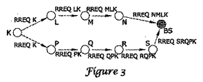
図3は、デバイスKについての経路の分散された構成を示す図である。例示の実施形態においては、Kは、他のデバイスL、M、N、P、Q、R、Sと、基地局BSをすでに有するシステムに対して新しく追加されたデバイスとすることができる。デバイスKは、その代わりに、それらのシステムの一部分であったが、例えば低電力スリープ期間後、または連絡を妨げる干渉(ノイズ)の期間後にそのシステムと連絡を再確立しているデバイスとすることもできる。デバイスKはまた、例えば他のデバイスがシステムに追加された後に、経路指定を再構成するコマンドを考慮に入れて、それ自体を再構成していてもよい。 FIG. 3 is a diagram illustrating a distributed configuration of paths for the device K. In the exemplary embodiment, K may be a newly added device to a system that already has other devices L, M, N, P, Q, R, S and a base station BS. Device K could instead be a device that was part of their system but has reestablished contact with the system, for example after a low power sleep period or after a period of interference (noise) that prevents contact. You can also. Device K may also reconfigure itself, taking into account commands to reconfigure routing, for example after other devices have been added to the system.
Kを追加する分散された構成は、以下のように行われてもよい。Kは、それ自体のアドレスKが続き、メッセージ「RREQK」を作成する、経路指定要求RREQを生成する。すぐ隣のデバイスL、Pが、Kからその経路指定要求を受信するときに、それぞれは、メッセージ中にそれ自体のアドレスを含めた後にメッセージを再送信することになる。他の情報、例えばRSSIデータ(受信信号強度インジケータ、他のリンク品質データ、またはノード待ち時間データ(例示の実施形態においては、ノード待ち時間は、ノードによってサービスされる経路数に比例する)を追加することもできる。ノード待ち時間データは、適切な任意の形式を取ることができる。別の例においては、ノード待ち時間データは、いくつかのノードまたは各ノードに、そのノードにおけるデータ(またはデータのパケット)の常駐時間上の統計を保持させることによって生成することができる。さらなる一例においては各ノードについての待ち時間値は、平均常駐時間、または待ち時間値としての常駐時間の組または分布に関連する統計値とすることができる。例えばデバイスが、必ずしも「ON」でない(すなわち、時々スリープモードに入る)場合に起こることもある間欠性の通信障害に対応するために、収集されたデータは、通信リンク障害のインジケータと、そのような障害の頻度を含むことができる。 A distributed configuration for adding K may be performed as follows. K generates a routing request RREQ, followed by its own address K, creating the message “RREQK”. When the immediately neighboring devices L, P receive their routing request from K, each will re-send the message after including its own address in the message. Add other information, eg RSSI data (received signal strength indicator, other link quality data, or node latency data (in the exemplary embodiment, node latency is proportional to the number of paths serviced by the node) Node latency data can take any suitable form, and in another example, node latency data can be sent to several nodes or each node with data (or data at that node). In a further example, the latency value for each node is a mean residence time, or a set or distribution of residence times as latency values. For example, the device is not necessarily “ON” In order to respond to intermittent communication failures that may occur if there is an occasional sleep mode), the collected data can include a communication link failure indicator and the frequency of such failures. .
次いでメッセージは、RREQが、宛先に、この場合には基地局BSに到達するまで反復される。図に示されるように、基地局は、Kから複数のRREQを受信することができる−この場合には、RREQNMLKは、それがKによって生成された後に、またそれがBSにおいて受信される前にノードL、M、およびNを通過する。同様に、RREQSRQPKは、それが生成された後に、またそれがBSにおいて受信される前にノードP、Q、R、およびSを通過する。次いで、基地局BSは、それらのメッセージを介してソートし、明らかに最良の経路を選択することになる。一般的に「最良の」経路は、最大のリンク強度と最小のホップ数を有する経路として決定される。基地局に最良の経路を選択させる際に考慮することができる他のファクタは、KとBSとの間の中間ノードのうちのいずれかの「負荷」を含む。例えば、高負荷の中間ノード(すでに多数の他の既存の経路の一部分を形成しているノード)を含む経路は、高負荷のノードにおけるデータ衝突を回避するために非選択状態にすることができる。 The message is then repeated until the RREQ reaches the destination, in this case the base station BS. As shown in the figure, the base station can receive multiple RREQs from K-in this case, RREQNMLK is after it is generated by K and before it is received at the BS. Pass through nodes L, M, and N. Similarly, RREQSRQPK passes through nodes P, Q, R, and S after it is generated and before it is received at the BS. The base station BS will then sort through those messages and obviously select the best route. In general, the “best” route is determined as the route with the maximum link strength and the minimum number of hops. Other factors that can be considered when allowing the base station to select the best path include the “load” of any of the intermediate nodes between K and BS. For example, a path that includes a high load intermediate node (a node that already forms part of a number of other existing paths) can be deselected to avoid data collisions at the high load node. .
BSが、最適の経路(または一部の実施形態においては2つ以上の最良の最適経路)を選択した後に、メッセージが、BSによって生成され、Kに対してどの1つ(または複数)の経路が使用されるべきかを示すためにKに対してアドレス指定される。一部の実施形態においては、メッセージをBSによって直接Kに送信することができるように、基地局BSは、すべての他のノードに対してブロードキャストするように使用可能にされる。他の実施形態においては、BSは、中間のデバイスを使用して、そのメッセージをKに対して経路指定することができる。分散された構成は、一般的に、ネットワーク内の通信とあまり干渉することなく実施することができる。しかし、デバイスKなどのデバイスは、追加し、アクティブにし、再アクティブにし、あるいはそうでなければランダムな順序で構成することができるので、分散された構成ルーチンは、多くの場合に最適な可能な構成とは異なる結果を達成する。しかし、中央に集中された構成ルーチンを使用した反復される再構成は、複雑になり、それ故に、計算の必要性および構成をアップデートするためのダウンタイムを考慮するとコストがかかる可能性がある。したがって本発明は、実際の構成が最適なものからどれだけ離れているかを決定して、再構成または他の改善が望ましいかどうかを決定するためのベンチマークを提供する。 After the BS has selected the best path (or more than one best best path in some embodiments), a message is generated by the BS and any one (or more) paths for K Is addressed to K to indicate whether should be used. In some embodiments, the base station BS is enabled to broadcast to all other nodes so that messages can be sent directly to K by the BS. In other embodiments, the BS can route the message to K using an intermediate device. A distributed configuration can generally be implemented without much interference with communications in the network. However, since devices such as device K can be added, activated, reactivated, or otherwise configured in a random order, a distributed configuration routine is often the best possible Achieve different results from the configuration. However, iterative reconfiguration using a centralized configuration routine is complicated and therefore can be costly considering the computational needs and downtime to update the configuration. Thus, the present invention provides a benchmark for determining how far the actual configuration is from the optimal and determining if reconfiguration or other improvements are desirable.
図3において、2つのオーバーラップしない冗長な経路が、Kが基地局BSに到達するために定義されていることを理解することができる。一方の経路は、シリーズK−L−M−N−BSに従う。他方の経路は、シリーズK−P−Q−R−S−BSに従う。これらの経路は、多くの場合に異なるホップ数を有するものと説明される、異なる長さを有する。中間局(一方の例においてはL、M、およびN、また他方ではP、Q、R、およびS)のうちの任意の局によって搬送される最大負荷は、経路ごとに異なる可能性がある。経路中の各リンクは、異なる信号強度を有することができる。また経路中の各ノードは、そこを通過する経路数に関する限り、異なる負荷を搬送することができる。これらのファクタのそれぞれは、例えばデータがBSに到達するために必要とされる時間量を、あるいはある経路がシステム中で使用される他の経路にどのように影響を及ぼすかを変化させることにより、システム性能に影響を及ぼす可能性がある。 In FIG. 3, it can be seen that two non-overlapping redundant paths are defined for K to reach the base station BS. One path follows the series KLMN-BS. The other path follows the series K-PQR-S-BS. These paths have different lengths, often described as having different hop numbers. The maximum load carried by any of the intermediate stations (L, M, and N in one example, and P, Q, R, and S in the other) may be different for each path. Each link in the path can have a different signal strength. Each node in the route can carry a different load as far as the number of routes passing therethrough is concerned. Each of these factors can vary, for example, by changing the amount of time required for data to reach the BS or how one path affects other paths used in the system. May affect system performance.
図4は、例示の一実施形態についてのフローチャートである。本方法10は、20に示されるように既存の無線システム中におけるリンク間のリンク特性を観察することによって開始される。少なくとも一部のノードが追加され、分散されるように通信経路が設けられている既存のシステムは、例えばオンとすることができる。別のステップにおいては、22に示されるように最適なソリューションが生成される。
FIG. 4 is a flowchart for one exemplary embodiment. The
例示の一実施形態においては、最適なソリューションは、混合整数線形プログラムの方法によって生成される。第1に、2つの冗長なオーバーラップしない経路が、図2および3において以上で示されるように、ノードごとに定義される。次いで混合整数線形プログラムが、以下の和を最小化させるように実行される。 In one exemplary embodiment, the optimal solution is generated by a mixed integer linear program method. First, two redundant non-overlapping paths are defined for each node, as shown above in FIGS. A mixed integer linear program is then run to minimize the following sum:
+α1*{ベースまでの各ノードの2つの冗長な経路上のホップ数の和}
−α2*{ノードごとの2つの経路中のすべてのリンク上の各リンクのリンク品質の対数の和}
+α3*{ネットワーク中の任意のノードによってサービスされる最大負荷}
+α4*{経路中における、各ノードの2つの経路上で各中間ノードによって導入される待ち時間の和}
例示の実施形態では、中間ノードによって導入される待ち時間は、そのノードによってサービスされる経路数に比例することもある。ノード待ち時間は、特定のノードにおけるデータの常駐時間を含めて、追加の測定基準を使用して、例えば様々な時刻に特定のノードを通過するデータについてのいくつかの常駐時間に関連する平均常駐時間または統計値を計算することにより、計算することもできる。変数α1...α4は、識別されるファクタのうちのどれが最も重要と考えられるかに応じてユーザが設定することができる。必要に応じて、以上で指摘された4つの値ではなくて、他のシステム変数を使用することができる。例えば、ネットワーク中の任意のノードによって満たされる最大負荷を使用するのではなく、ノード負荷の統計的変数を使用することができる。同様に、ノードにおけるパケットの待機する遅延(または常駐時間)の分布の統計的平均は、待ち時間測定値のために使用することもできる。
+ Α1 * {the sum of the number of hops on two redundant paths for each node up to the base}
-Α2 * {Sum of the log quality of the link quality of each link on all links in the two paths per node}
+ Α3 * {maximum load serviced by any node in the network}
+ Α4 * {sum of latency introduced by each intermediate node on the two paths of each node in the path}
In the exemplary embodiment, the latency introduced by an intermediate node may be proportional to the number of paths serviced by that node. Node latency is the average residence time associated with several residence times for data passing through a particular node at various times, for example using additional metrics, including the residence time of the data at a particular node It can also be calculated by calculating time or statistics. Variable α1. . . α4 can be set by the user depending on which of the identified factors is considered the most important. If desired, other system variables can be used instead of the four values noted above. For example, instead of using the maximum load satisfied by any node in the network, a statistical variable of node load can be used. Similarly, a statistical average of the waiting delay (or resident time) distribution of packets at a node can be used for latency measurements.
例示の実施形態においては、次いでα変数を含めて以上のファクタの組を使用して、図4中のステップ24に示されるように第1の品質測定基準を生成する。この測定基準は、例えば数字とすることができる。次に26に示されるように、システムの実際の経路指定特性が観察される。同じ組のα変数を有する以上の式中で使用されるような経路指定特性を使用する第2の品質測定基準が、28に示されるように生成される。最後に、第1の品質測定基準と第2の品質測定基準が、ステップ30に示されるように、比較される。本システムでは、第1の品質測定基準と第2の品質測定基準の比較が、再構成についての必要性を示すときに、再構成を行うことができる。例えば、第1の品質測定基準が、第2の品質測定基準のあらかじめ選択されたパーセンテージ(例えば、75%、または他の任意の値)である場合に、再構成を実装するために必要とされる計算および通信の費用に見合うように、再構成の結果としての25%の改善が再構成から期待することができる。
In the exemplary embodiment, the above set of factors, including the α variable, is then used to generate a first quality metric as shown in
例示の一実施形態においては、インフラストラクチャノードに関連する物理情報は、相対的並列配置およびノード間のリンク強度を含めて、それらの物理特性で表して特徴付けられる。基地局を含めて頂点の集合が、すべてのノードの集合であるグラフG(V,E)が定義される。グラフの辺は、頂点の間の通信接続を示す有向辺である。例えば、頂点Aと頂点Bとの間の有向辺が存在する場合、次いでAからBへの可能な通信が存在する。次いで、基地局に対する、2つまたは(より多くの)最良のオーバーラップしない経路が選択される。以上で指摘されたファクタを考慮に入れたグラフ解析を使用することにより、最適なソリューションに近づけることができる。 In one exemplary embodiment, physical information associated with infrastructure nodes is characterized and expressed in terms of their physical characteristics, including relative parallel placement and link strength between nodes. A graph G (V, E) in which a set of vertices including a base station is a set of all nodes is defined. The edges of the graph are directed edges that indicate communication connections between vertices. For example, if there is a directed edge between vertex A and vertex B, then there is a possible communication from A to B. The two or (more) best non-overlapping paths for the base station are then selected. By using a graph analysis that takes into account the factors pointed out above, we can approach an optimal solution.
一部の実施形態においては、以上で指摘されたファクタのすべてよりも少ないファクタが最小化プロセスのために考慮される。代わりに、1つまたは複数のファクタが取り除かれるように、α1...α4のうちの1つまたは複数をゼロに設定することができる。 In some embodiments, fewer than all of the factors noted above are considered for the minimization process. Instead, α1... So that one or more factors are removed. . . One or more of α4 can be set to zero.
以上の式および無線ネットワークシミュレータを使用して、様々な試行が実施された。分散されたアプローチは、無線ネットワークシミュレータ中で使用されたとき、グローバルシステムを設計することに対する中央に集中されたアプローチを使用するアプローチほど良好でないことが見出された。例えば、第1のファクタ(ホップ数)だけを考慮に入れると、中央に集中されたアプローチは、一般的に分散されたアプローチよりも7〜10%良好な(すなわち、7〜10%ホップの少ない)範囲にある。しかし、以上で指摘されるように、中央に集中されたアプローチに完全に依存することは、その実用性を限定する他の難点を引き起こす可能性がある。 Various trials were conducted using the above equations and a wireless network simulator. The distributed approach has been found to be not as good as an approach that uses a centralized approach to designing global systems when used in a wireless network simulator. For example, taking into account only the first factor (number of hops), a centralized approach is typically 7-10% better (ie, 7-10% fewer hops) than a distributed approach ) Is in range. However, as pointed out above, full reliance on a centralized approach can cause other difficulties that limit its utility.
本発明の状況においては、経路指定することに対する中央に集中されたアプローチを、最適化されたアプローチと考えることができる。「最適な」アプローチを生み出す際に必要とされるいくつかのファクタが存在するので、実際には、単一の「最適な」経路指定アプローチが存在することはまれであることを理解されたい。その代わりに、通信品質を決定する1つまたは複数のファクタの観点から最適化することができる最適化された通信ソリューションが存在する。中央に集中されたソリューションは、最適化されたソリューションの1つのカテゴリである。中央に集中されたソリューションの組のうちには、様々なファクタについて最適化されたソリューションが存在する。本明細書中において例示の実施形態は、使用される通信ホップ数、システム待ち時間、および/またはシステム中の任意のノードによって満たされ、かつ/またはネットワーク内のリンク品質を最大にする最大負荷を低減させるように最適化された中央に集中されたソリューションとすることができる最適化された通信ソリューションを含む例を提供する。 In the context of the present invention, a centralized approach to routing can be considered an optimized approach. It should be understood that in practice there is rarely a single “optimal” routing approach, as there are several factors that are required in creating an “optimal” approach. Instead, there are optimized communication solutions that can be optimized in terms of one or more factors that determine communication quality. Centralized solutions are one category of optimized solutions. Within the centralized set of solutions, there are solutions that are optimized for various factors. The exemplary embodiments herein provide a maximum load that is satisfied by the number of communication hops used, system latency, and / or any node in the system and / or maximizes link quality in the network. An example is provided that includes an optimized communication solution that can be a centralized solution that is optimized to reduce.
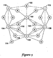
図5は、一例の無線センサネットワークを示している。そのネットワークは、ゲートウェイノードまたはベースノード100と、いくつかのインフラストラクチャノード102、104、106、108、110、112と、センサSとして示されるいくつかのリーフノードを含んでいる。どの1つのインフラストラクチャノードの障害も、完全にはセンサをネットワークから切り離すことにならないように、各センサは、それ自体を2つのインフラストラクチャノードに関連付ける。一部の実施形態においては、ネットワークは、その開示が参照により本明細書に組み込まれている2004年6月17日に出願の「チャネルホッピングと冗長な接続を伴う無線通信システム(WIRESS COMMUNICATION SYSTEM WITH CHANNEL HOPPING AND REDUNDANT CONNECTIVITY(チャンネルホッピングおよび冗長接続を備えた無線通信システム)」という名称の同時係属の米国特許出願第10/870,295号に説明されるような形式を取る。
FIG. 5 illustrates an example wireless sensor network. The network includes a gateway node or
一実施形態においては、少なくとも一部のセンサは、低電力モードで動作する。例えば、所与のセンサは、アクティブモードと低電力スリープモードを有することができ、ここで、センサは、定期的に低電力スリープモードから覚醒し、アクティブモードを使用してデータを送信する。低電力スリープ中にある間、センサは、通信のためには使用不可能である。スケジュールされた時刻に、センサは覚醒することができ、どのようなデータをセンサが送信するために収集しているとしても関連するインフラストラクチャノードに対して送信する。次に、インフラストラクチャノードは、そのセンサデータを基地局に対して送信する。 In one embodiment, at least some sensors operate in a low power mode. For example, a given sensor can have an active mode and a low power sleep mode, where the sensor periodically wakes up from the low power sleep mode and transmits data using the active mode. While in low power sleep, the sensor is not available for communication. At the scheduled time, the sensor can wake up and transmit whatever data the sensor is collecting to transmit to the associated infrastructure node. Next, the infrastructure node transmits the sensor data to the base station.
冗長性の目的のために、センサは、2つのインフラストラクチャノードに対して送信することができる。例えば、いくつかのセンサ114、116、118は、インフラストラクチャノード104、106のそれぞれに関連付けて示されている。一部の実施形態においては、インフラストラクチャノード104、106を通過するこれらのセンサ114、116、118からの信号についての経路が、オーバーラップしないように、本システムは構成される。例えば、第1のセンサ114からの信号は、インフラストラクチャノード104および110へと、次いでベースノード100へと、またインフラストラクチャノード106へも、次いでまたベースノード100へと経路指定することができる。その間に、第2のセンサ116からの信号は、同じ経路対を有することができる。ノード102は、いくつかのセンサ伝送のために使用される可能性が高いことが、図示されるシステムから理解することができる。システムの全体的待ち時間を低減させるために、ノード102を介して経路指定することができるあるデータは、ノード2の周囲で経路指定して、データ衝突の可能性を低減させることができる。したがって、センサ118などのセンサからのデータは、インフラストラクチャノード104および110へと、次いでベースノード100へと、ならびにベースノード100へと進む前にノード106、108、および112へと渡すことによりノード102の周囲で経路指定することができる。
For redundancy purposes, the sensor can transmit to two infrastructure nodes. For example,
経路指定することに対する分散されたアプローチと共に生じ得る難点のうちの1つを強調するために、センサ120が本システムに追加されるものと仮定する。図から分かるように、センサ120は、ノード102および108への関連付けが望ましいように配置される。センサ120は、同様にノード106と通信を行うために十分に近くすることもできるが、明らかにノード102により近い。しかし、センサ120が本システムに追加された最新のセンサである場合、次いでノード102は、すでに本システムの最も重い経路指定負荷を搬送していることもある。ノード102が、すでに負荷を経路指定するためのその最大限度(そのような容量は、本システムではあらかじめ定義することができる)にある場合、次いでノード102は、センサ120からの信号を経路指定するためには使用できないはずである。これは、センサ120がノード106および108に関連することを必要とするはずであり、センサ120からノード106へと通過する信号が、ベースノード100に到達する前にノード104および110へと再送信されるように強制するはずである。結果は、非効率的である。しかし、新しいセンサが追加されるたびに、センサが取り除かれるたびに、センサがその関連するインフラストラクチャノードとの通信を失うたびに、通信を失っているセンサが通信を回復するたびに、また同様にインフラストラクチャノードが追加され、取り除かれ、または通信を失い回復する他のときに、全体の経路指定テーブルを再構成することは、構成信号を経路指定することの不協和音を生成する可能性が高いはずである。それ故に、本発明を用いて、最適な性能に対する実際の性能を比較し、測定することができる。
Assume that a
実際の性能が、望ましいしきい値より下に下がるときに、次いで本システムは、中央に集中されるように、または分散されるように再構成することができる。例えば、測定基準が図4を参照して以上で説明されるように生成される場合、また実際のシステム測定基準が所定の比率による理想化されたスコアよりも高いスコアを示す場合には、次いで本システムを再構成することができる。例えば、実際のシステム測定基準に対する理想化された測定基準の比率が75%よりも下に下がる場合には、次いで本システムを再構成することができる。他の比率を使用することもでき、より高い比率は、再構成がより頻繁に起こることを許すが、より高い効率をも確実にする可能性が高い。 When the actual performance falls below a desired threshold, the system can then be reconfigured to be centralized or distributed. For example, if a metric is generated as described above with reference to FIG. 4 and if the actual system metric shows a higher score than the idealized score by a predetermined ratio, then The system can be reconfigured. For example, if the ratio of idealized metric to actual system metric falls below 75%, the system can then be reconfigured. Other ratios can be used, and a higher ratio will allow reconfiguration to occur more frequently, but will likely also ensure higher efficiency.
本システム中の任意のデバイスは、本発明に関連する解析を実施するようにプログラムすることができる。代わりに、そのような解析を実施するために、別個のデバイスを本システムに通信を行うように結合することができる。必要に応じて、基地局は、システム性能データを収集し、そのデータを本システムの一部分でない別のデバイス(例えば、基地局によってアクセス可能な有線ネットワークを使用してアクセス可能なデバイス)に送信することができる。最適化されたソリューションは、余分なコンピューティング能力を必要とすることもあるので、性能データを送信することができることは、本システムが動作している間でさえ、システム解析を行うことを可能にする上で助けとなる可能性がある。 Any device in the system can be programmed to perform the analysis associated with the present invention. Alternatively, a separate device can be communicatively coupled to the system to perform such analysis. If necessary, the base station collects system performance data and transmits the data to another device that is not part of the system (eg, a device accessible using a wired network accessible by the base station). be able to. Optimized solutions may require extra computing power, so the ability to transmit performance data allows system analysis to be performed even while the system is operating May help you.
当業者なら、本発明は、本明細書中で説明され、企図される特定の実施形態以外の様々な形態で明らかに示すことができることを理解されよう。したがって、形態および詳細における逸脱は、添付の特許請求の範囲において説明されるように、本発明の範囲および趣旨を逸脱することなしに、行うことができる。 Those skilled in the art will appreciate that the present invention can be clearly shown in various forms other than the specific embodiments described and contemplated herein. Accordingly, departures in form and detail may be made without departing from the scope and spirit of the invention as set forth in the appended claims.
Claims (23)
前記システム中のデバイス対のリンク特性を観察するステップと、
前記リンク特性を使用して、最適化された通信ソリューションを生成するステップと、
前記最適化された通信ソリューションを使用して第1の品質測定基準を計算するステップと、
前記ノードデバイスについての前記実際の通信構成を観察し、第2の品質測定基準を生成するステップと、
前記第1の品質測定基準を前記第2の品質測定基準と比較するステップと、
を含む方法。 A method of analyzing the performance of a wireless communication system, comprising a base station and several node devices, operating in an actual communication configuration using a communication link between device pairs in the system,
Observing link characteristics of device pairs in the system;
Using the link characteristics to generate an optimized communication solution;
Calculating a first quality metric using the optimized communication solution;
Observing the actual communication configuration for the node device and generating a second quality metric;
Comparing the first quality metric with the second quality metric;
Including methods.
前記実際の通信構成もまた、ノードデバイスごとに、前記基地局に対する第1および第2のオーバーラップしない通信経路を定義し、少なくとも一部の定義された通信経路が、前記ノードデバイスと前記基地局との間の中間ノードを含み、
前記第1および第2の品質測定基準は、少なくとも一部の定義された通信経路中の各中間ノードによって導入される待ち時間の和に関連する成分を含み、
前記第1および第2の品質測定基準は、少なくとも1つのノードデバイスと前記基地局との間のホップ数に関連する成分を含み、
前記第1および第2の品質測定基準は、少なくとも1つのノードデバイスと前記基地局との間で定義される経路中で使用されるリンクのリンク品質に関連する成分を含み、
前記第1および第2の品質測定基準は、中間ノードで現れるオーバーラップする経路の数に関連する成分を含む、請求項1に記載の方法。 The optimized communication solution is characterized in that for each node device, first and second non-overlapping communication paths to the base station are defined;
The actual communication configuration also defines first and second non-overlapping communication paths for the base station for each node device, and at least some of the defined communication paths are defined between the node device and the base station. Including intermediate nodes between
The first and second quality metrics include a component related to a sum of latency introduced by each intermediate node in at least some defined communication paths;
The first and second quality metrics include a component related to the number of hops between at least one node device and the base station;
The first and second quality metrics include components related to link quality of links used in a path defined between at least one node device and the base station;
The method of claim 1, wherein the first and second quality metrics include components related to the number of overlapping paths that appear at an intermediate node.
前記システム中における、または前記システムに対して通信を行うように結合された少なくとも1つの解析するデバイスが、前記システムにおいて定義される実際の通信経路に関連するデータを収集し、前記システムの通信ステータスの実際の品質測定基準を観察するように構成され、
前記解析するデバイスは、さらに前記実際の品質測定基準と比較するための、最適化された通信ソリューションに基づいた最適な品質測定基準を生成するように構成される、無線通信システム。 A wireless communication system comprising at least one base station and several node devices configured to wirelessly communicate with each other,
At least one analyzing device in or coupled to communicate with the system collects data relating to actual communication paths defined in the system, and the communication status of the system Configured to observe the actual quality metrics of
The wireless communication system, wherein the analyzing device is further configured to generate an optimal quality metric based on an optimized communication solution for comparison with the actual quality metric.
少なくとも1つの実際の通信経路は、中間ノードを含み、
前記実際の品質測定基準および最適な品質測定基準は、中間ノードで現れるオーバーラップする経路の数に関連する成分を含む、請求項11に記載のシステム。 Several optimal communication paths are defined when mathematically optimal metrics are generated, and at least one optimal communication path is an intermediate node that carries data from the first node to the base station Have
At least one actual communication path includes an intermediate node;
The system of claim 11, wherein the actual quality metric and the optimal quality metric include a component related to the number of overlapping paths that appear at an intermediate node.
実際の通信構成は、ノードデバイスごとに前記基地局に対する第1および第2のオーバーラップしない通信経路を定義し、少なくとも一部の定義された通信経路が、前記ノードデバイスと前記基地局との間の中間ノードを含み、
前記実際の品質測定基準および最適な品質測定基準は、少なくとも一部の定義された通信経路において各中間ノードによって導入される待ち時間の和に関連する成分を含み、
前記実際の品質測定基準および最適な品質測定基準は、第1のノードデバイスと前記基地局との間のホップ数に関連する成分を含み、
前記実際の品質測定基準および最適な品質測定基準は、第1のノードデバイスと前記基地局との間で定義される経路において使用されるリンクのリンク品質に関連する成分を含み、
前記実際の品質測定基準および最適な品質測定基準は、中間ノードで現れるオーバーラップする経路の数に関連する成分を含む、請求項11に記載のシステム。 For each node device, the first and second or more non-overlapping communication paths to the base station are defined when a mathematically optimal quality metric is generated,
The actual communication configuration defines first and second non-overlapping communication paths for the base station for each node device, and at least some defined communication paths are between the node device and the base station. Intermediate nodes,
The actual quality metric and the optimal quality metric include a component related to a sum of latency introduced by each intermediate node in at least some defined communication paths;
The actual quality metric and the optimal quality metric include a component related to the number of hops between a first node device and the base station;
The actual quality metric and the optimal quality metric include components related to link quality of links used in a path defined between a first node device and the base station;
The system of claim 11, wherein the actual quality metric and the optimal quality metric include a component related to the number of overlapping paths that appear at an intermediate node.
前記数学的に最適な測定基準の前記実際の測定基準との比較は、所定のレベルを超えるシステムの非効率性を示す場合に、新しい経路指定スキームが、前記第1の経路指定スキームを置き換えるように生成される、請求項11に記載のシステム。 The system is configured to have a first routing protocol for routing data to a base station via the system;
If the comparison of the mathematically optimal metric with the actual metric indicates a system inefficiency exceeding a predetermined level, a new routing scheme will replace the first routing scheme. The system of claim 11, wherein
前記システム中における、または前記システムに対して通信を行うように結合された少なくとも1つの解析するデバイスは、前記システムにおいて定義される実際の通信経路に関連するデータを収集し、前記システムの通信ステータスの実際の品質測定基準を観察するように構成され、
前記解析するデバイスは、さらに実際の通信経路に関連する前記データを使用して最適化された通信構成を構築することにより、最適な品質測定基準を生成するように構成される、無線通信システム。 A wireless communication system comprising at least one base station, a number of infrastructure node devices configured to wirelessly communicate with each other, and a number of leaf devices in communication with the infrastructure node devices,
At least one analyzing device in or coupled to communicate with the system collects data relating to an actual communication path defined in the system, and the communication status of the system Configured to observe the actual quality metrics of
The wireless communication system, wherein the analyzing device is further configured to generate an optimal quality metric by constructing an optimized communication configuration using the data associated with an actual communication path.
前記数学的に最適な測定基準の前記実際の測定基準との比較が、所定のレベルを超えるシステムの非効率性を示す場合に、新しい経路指定スキームが、前記第1の経路指定スキームを置き換えるように生成される、請求項20に記載のシステム。 The system is configured to have a first routing scheme for routing data to the base station via the system;
A new routing scheme replaces the first routing scheme when comparison of the mathematically optimal metric with the actual metric indicates a system inefficiency that exceeds a predetermined level 21. The system of claim 20, wherein the system is generated.
Applications Claiming Priority (2)
| Application Number | Priority Date | Filing Date | Title |
|---|---|---|---|
| US10/905,971 US7826373B2 (en) | 2005-01-28 | 2005-01-28 | Wireless routing systems and methods |
| PCT/US2006/000018 WO2006083461A1 (en) | 2005-01-28 | 2006-01-03 | Wireless routing systems and methods |
Publications (2)
| Publication Number | Publication Date |
|---|---|
| JP2008529410A true JP2008529410A (en) | 2008-07-31 |
| JP2008529410A5 JP2008529410A5 (en) | 2008-11-20 |
Family
ID=36216992
Family Applications (1)
| Application Number | Title | Priority Date | Filing Date |
|---|---|---|---|
| JP2007553108A Pending JP2008529410A (en) | 2005-01-28 | 2006-01-03 | System and method for performing wireless routing |
Country Status (5)
| Country | Link |
|---|---|
| US (1) | US7826373B2 (en) |
| EP (1) | EP1856858B1 (en) |
| JP (1) | JP2008529410A (en) |
| CN (1) | CN101151857A (en) |
| WO (1) | WO2006083461A1 (en) |
Families Citing this family (42)
| Publication number | Priority date | Publication date | Assignee | Title |
|---|---|---|---|---|
| US20060004714A1 (en) * | 2004-06-30 | 2006-01-05 | Ibm Corporation | Transposition search method for optimal topology construction |
| US7315533B2 (en) * | 2005-04-08 | 2008-01-01 | Cisco Technology, Inc. | Radio plan generator |
| US8285326B2 (en) * | 2005-12-30 | 2012-10-09 | Honeywell International Inc. | Multiprotocol wireless communication backbone |
| US9113362B2 (en) * | 2006-12-12 | 2015-08-18 | At&T Mobility Ii Llc | Method and apparatus to separate coverage limited and co-channel limited interferences |
| US8107511B2 (en) * | 2007-04-30 | 2012-01-31 | Honeywell International Inc. | Apparatus and method for intelligent frequency-hopping discovery and synchronization |
| US7933240B2 (en) * | 2007-07-19 | 2011-04-26 | Honeywell International Inc. | Apparatus and method for redundant connectivity and multi-channel operation of wireless devices |
| US7881253B2 (en) | 2007-07-31 | 2011-02-01 | Honeywell International Inc. | Apparatus and method supporting a redundancy-managing interface between wireless and wired networks |
| US8280057B2 (en) | 2007-09-04 | 2012-10-02 | Honeywell International Inc. | Method and apparatus for providing security in wireless communication networks |
| US8458778B2 (en) * | 2007-09-04 | 2013-06-04 | Honeywell International Inc. | System, method, and apparatus for on-demand limited security credentials in wireless and other communication networks |
| US8413227B2 (en) | 2007-09-28 | 2013-04-02 | Honeywell International Inc. | Apparatus and method supporting wireless access to multiple security layers in an industrial control and automation system or other system |
| US8681676B2 (en) | 2007-10-30 | 2014-03-25 | Honeywell International Inc. | System and method for providing simultaneous connectivity between devices in an industrial control and automation or other system |
| KR100970385B1 (en) * | 2008-06-09 | 2010-07-15 | 한국전자통신연구원 | Method and apparatus routing for wireless network |
| US8107390B2 (en) * | 2008-07-21 | 2012-01-31 | Honeywell International Inc. | Apparatus and method for deterministic latency-controlled communications in process control systems |
| US9500736B2 (en) * | 2008-07-31 | 2016-11-22 | Honeywell International Inc. | System and method for providing self-locating wireless sensors |
| US8633853B2 (en) | 2008-07-31 | 2014-01-21 | Honeywell International Inc. | Method and apparatus for location detection using GPS and WiFi/WiMAX |
| US8755814B2 (en) * | 2008-07-31 | 2014-06-17 | Honeywell International Inc. | Method and apparatus for intermittent location reporting |
| US8107989B2 (en) * | 2008-07-31 | 2012-01-31 | Honeywell International, Inc. | Apparatus and method for transmit power control in a wireless network |
| US8350666B2 (en) | 2008-10-15 | 2013-01-08 | Honeywell International Inc. | Apparatus and method for location-based access control in wireless networks |
| US8837354B2 (en) | 2009-04-24 | 2014-09-16 | Honeywell International Inc. | Apparatus and method for supporting wireless actuators and other devices in process control systems |
| US8325628B2 (en) * | 2009-07-09 | 2012-12-04 | International Business Machines Corporation | Determining placement of nodes within a wireless network |
| US8498201B2 (en) | 2010-08-26 | 2013-07-30 | Honeywell International Inc. | Apparatus and method for improving the reliability of industrial wireless networks that experience outages in backbone connectivity |
| US8924498B2 (en) | 2010-11-09 | 2014-12-30 | Honeywell International Inc. | Method and system for process control network migration |
| US8665890B2 (en) | 2011-05-20 | 2014-03-04 | The Regents Of The University Of California | Hybrid cross-layer routing protocol for MANETs |
| US8789001B1 (en) * | 2013-02-20 | 2014-07-22 | Tabula, Inc. | System and method for using fabric-graph flow to determine resource costs |
| US9110838B2 (en) | 2013-07-31 | 2015-08-18 | Honeywell International Inc. | Apparatus and method for synchronizing dynamic process data across redundant input/output modules |
| US9720404B2 (en) | 2014-05-05 | 2017-08-01 | Honeywell International Inc. | Gateway offering logical model mapped to independent underlying networks |
| US10042330B2 (en) | 2014-05-07 | 2018-08-07 | Honeywell International Inc. | Redundant process controllers for segregated supervisory and industrial control networks |
| US10405201B2 (en) * | 2014-05-08 | 2019-09-03 | Telefonaktiebolaget Lm Ericsson (Publ) | Re-configuration of RBS performance mode |
| US9609524B2 (en) | 2014-05-30 | 2017-03-28 | Honeywell International Inc. | Apparatus and method for planning and validating a wireless network |
| US10536526B2 (en) | 2014-06-25 | 2020-01-14 | Honeywell International Inc. | Apparatus and method for virtualizing a connection to a node in an industrial control and automation system |
| US9699022B2 (en) | 2014-08-01 | 2017-07-04 | Honeywell International Inc. | System and method for controller redundancy and controller network redundancy with ethernet/IP I/O |
| US10148485B2 (en) | 2014-09-03 | 2018-12-04 | Honeywell International Inc. | Apparatus and method for on-process migration of industrial control and automation system across disparate network types |
| US10212087B2 (en) * | 2014-09-17 | 2019-02-19 | Vivint, Inc. | Mesh network assessment and transmission |
| WO2016070947A1 (en) * | 2014-11-05 | 2016-05-12 | Telefonaktiebolaget L M Ericsson (Publ) | Transmitting residence time information in a network |
| US10162827B2 (en) | 2015-04-08 | 2018-12-25 | Honeywell International Inc. | Method and system for distributed control system (DCS) process data cloning and migration through secured file system |
| US10409270B2 (en) | 2015-04-09 | 2019-09-10 | Honeywell International Inc. | Methods for on-process migration from one type of process control device to different type of process control device |
| US10296482B2 (en) | 2017-03-07 | 2019-05-21 | Honeywell International Inc. | System and method for flexible connection of redundant input-output modules or other devices |
| US10749692B2 (en) | 2017-05-05 | 2020-08-18 | Honeywell International Inc. | Automated certificate enrollment for devices in industrial control systems or other systems |
| US10401816B2 (en) | 2017-07-20 | 2019-09-03 | Honeywell International Inc. | Legacy control functions in newgen controllers alongside newgen control functions |
| US10616085B2 (en) | 2017-08-31 | 2020-04-07 | Zte Corporation | Residence time measurement for optimizing network services |
| US11477100B2 (en) * | 2017-09-26 | 2022-10-18 | Zte Corporation | Residence time measurement for traffic engineered network |
| BR112022011628A2 (en) * | 2019-12-13 | 2022-08-30 | Quarter Inc | METHODS FOR TRANSMITTING INFORMATION |
Citations (4)
| Publication number | Priority date | Publication date | Assignee | Title |
|---|---|---|---|---|
| WO2002024547A1 (en) * | 2000-09-20 | 2002-03-28 | Mitsubishi Pencil Kabushiki Kaisha | Solid matter delivering container |
| WO2003000781A1 (en) * | 2001-06-25 | 2003-01-03 | Gaska Tape, Inc. | Low volatility cellular foam |
| WO2004015904A2 (en) * | 2002-08-08 | 2004-02-19 | Harris Corporation | Multiple path reactive routing in a mobile ad hoc network |
| JP2004282270A (en) * | 2003-03-13 | 2004-10-07 | Sony Corp | Radio ad hoc communication system, terminal, processing method therein, and program for making terminal to execute the method |
Family Cites Families (74)
| Publication number | Priority date | Publication date | Assignee | Title |
|---|---|---|---|---|
| US3643183A (en) | 1970-05-19 | 1972-02-15 | Westinghouse Electric Corp | Three-amplifier gyrator |
| NL7113893A (en) | 1971-10-09 | 1973-04-11 | ||
| US3715693A (en) | 1972-03-20 | 1973-02-06 | J Fletcher | Gyrator employing field effect transistors |
| US4264874A (en) | 1978-01-25 | 1981-04-28 | Harris Corporation | Low voltage CMOS amplifier |
| US4529947A (en) | 1979-03-13 | 1985-07-16 | Spectronics, Inc. | Apparatus for input amplifier stage |
| GB2186156B (en) | 1983-10-21 | 1988-01-06 | Philips Electronic Associated | A receiver for frequency hopped signals |
| US4614945A (en) | 1985-02-20 | 1986-09-30 | Diversified Energies, Inc. | Automatic/remote RF instrument reading method and apparatus |
| FR2602380B1 (en) | 1986-07-30 | 1988-10-21 | Labo Electronique Physique | GYRATOR CIRCUIT SIMULATING AN INDUCTANCE |
| CH673184A5 (en) | 1987-05-19 | 1990-02-15 | Bbc Brown Boveri & Cie | Mobile radio communication system - has each mobile station switched in synchronism with interrogation by central station |
| FI86124C (en) | 1990-11-15 | 1992-07-10 | Telenokia Oy | RADIOSAENDARMOTTAGARSYSTEM. |
| DE4243026C2 (en) | 1992-12-18 | 1994-10-13 | Grundig Emv | Radio alarm system with asynchronous transmission of messages via time channels of different periods |
| US5438329A (en) | 1993-06-04 | 1995-08-01 | M & Fc Holding Company, Inc. | Duplex bi-directional multi-mode remote instrument reading and telemetry system |
| US5467664A (en) * | 1993-07-26 | 1995-11-21 | Black River Manufacturing, Inc. | Noise abating vehicle transmission shift lever |
| US5392003A (en) | 1993-08-09 | 1995-02-21 | Motorola, Inc. | Wide tuning range operational transconductance amplifiers |
| US5451898A (en) | 1993-11-12 | 1995-09-19 | Rambus, Inc. | Bias circuit and differential amplifier having stabilized output swing |
| DE4344172C2 (en) | 1993-12-23 | 2001-02-22 | Grundig Ag | Method and arrangement for synchronizing the outdoor units of a radio alarm system with the central unit |
| US5481259A (en) | 1994-05-02 | 1996-01-02 | Motorola, Inc. | Method for reading a plurality of remote meters |
| US5430409A (en) | 1994-06-30 | 1995-07-04 | Delco Electronics Corporation | Amplifier clipping distortion indicator with adjustable supply dependence |
| US5477188A (en) | 1994-07-14 | 1995-12-19 | Eni | Linear RF power amplifier |
| US5428637A (en) | 1994-08-24 | 1995-06-27 | The United States Of America As Represented By The Secretary Of The Army | Method for reducing synchronizing overhead of frequency hopping communications systems |
| ES2153849T3 (en) | 1994-11-07 | 2001-03-16 | Cit Alcatel | TRANSMISSION MIXER WITH INPUT IN CURRENT MODE. |
| US5659303A (en) | 1995-04-20 | 1997-08-19 | Schlumberger Industries, Inc. | Method and apparatus for transmitting monitor data |
| US5809013A (en) | 1996-02-09 | 1998-09-15 | Interactive Technologies, Inc. | Message packet management in a wireless security system |
| US5987011A (en) * | 1996-08-30 | 1999-11-16 | Chai-Keong Toh | Routing method for Ad-Hoc mobile networks |
| US5767664A (en) | 1996-10-29 | 1998-06-16 | Unitrode Corporation | Bandgap voltage reference based temperature compensation circuit |
| AU730712B2 (en) * | 1996-11-07 | 2001-03-15 | Nec Corporation | Method for determining optimal parent terminal and ad hoc network for the same |
| US6091715A (en) | 1997-01-02 | 2000-07-18 | Dynamic Telecommunications, Inc. | Hybrid radio transceiver for wireless networks |
| US5963650A (en) | 1997-05-01 | 1999-10-05 | Simionescu; Dan | Method and apparatus for a customizable low power RF telemetry system with high performance reduced data rate |
| FR2765763B1 (en) | 1997-07-07 | 1999-09-24 | Alsthom Cge Alcatel | PROCESS FOR DETERMINING A TIME ADVANCE INFORMATION IN A CELLULAR RADIOCOMMUNICATION SYSTEM, CORRESPONDING INTERCELLULAR TRANSFER PROCESS AND LOCATION PROCESS |
| US6236642B1 (en) * | 1997-07-17 | 2001-05-22 | Siemens Information And Communication Networks, Inc. | Apparatus and method for network resource preservation |
| US5847623A (en) | 1997-09-08 | 1998-12-08 | Ericsson Inc. | Low noise Gilbert Multiplier Cells and quadrature modulators |
| US6058137A (en) | 1997-09-15 | 2000-05-02 | Partyka; Andrzej | Frequency hopping system for intermittent transmission |
| SE511823C2 (en) | 1997-11-07 | 1999-12-06 | Ericsson Telefon Ab L M | Data communication networks and method related thereto |
| US6175860B1 (en) | 1997-11-26 | 2001-01-16 | International Business Machines Corporation | Method and apparatus for an automatic multi-rate wireless/wired computer network |
| US6700939B1 (en) | 1997-12-12 | 2004-03-02 | Xtremespectrum, Inc. | Ultra wide bandwidth spread-spectrum communications system |
| US6529730B1 (en) * | 1998-05-15 | 2003-03-04 | Conexant Systems, Inc | System and method for adaptive multi-rate (AMR) vocoder rate adaption |
| US6414963B1 (en) | 1998-05-29 | 2002-07-02 | Conexant Systems, Inc. | Apparatus and method for proving multiple and simultaneous quality of service connects in a tunnel mode |
| AU1443400A (en) | 1998-10-06 | 2000-04-26 | Slc Technologies, Inc. | Wireless home fire and security alarm system |
| US6353846B1 (en) | 1998-11-02 | 2002-03-05 | Harris Corporation | Property based resource manager system |
| US6052600A (en) | 1998-11-23 | 2000-04-18 | Motorola, Inc. | Software programmable radio and method for configuring |
| US6366622B1 (en) | 1998-12-18 | 2002-04-02 | Silicon Wave, Inc. | Apparatus and method for wireless communications |
| US6414955B1 (en) * | 1999-03-23 | 2002-07-02 | Innovative Technology Licensing, Llc | Distributed topology learning method and apparatus for wireless networks |
| US6901066B1 (en) * | 1999-05-13 | 2005-05-31 | Honeywell International Inc. | Wireless control network with scheduled time slots |
| US20020011923A1 (en) | 2000-01-13 | 2002-01-31 | Thalia Products, Inc. | Appliance Communication And Control System And Appliance For Use In Same |
| US6795418B2 (en) * | 2000-03-31 | 2004-09-21 | Koninklijke Philips Electronics N.V. | Wireless MAC protocol based on a hybrid combination of slot allocation, token passing, and polling for isochronous traffic |
| US6768901B1 (en) | 2000-06-02 | 2004-07-27 | General Dynamics Decision Systems, Inc. | Dynamic hardware resource manager for software-defined communications system |
| EP1224742B1 (en) | 2000-07-07 | 2011-05-18 | Sony Corporation | Universal platform for software defined radio |
| US7002910B2 (en) | 2000-10-30 | 2006-02-21 | The Regents Of The University Of California | Receiver-initiated channel-hopping (RICH) method for wireless communication networks |
| US7433683B2 (en) | 2000-12-28 | 2008-10-07 | Northstar Acquisitions, Llc | System for fast macrodiversity switching in mobile wireless networks |
| AU2002306749A1 (en) | 2001-03-13 | 2002-09-24 | Shiv Balakrishnan | An architecture and protocol for a wireless communication network to provide scalable web services to mobile access devices |
| US6944121B1 (en) * | 2001-03-19 | 2005-09-13 | Cisco Systems Wireless Networking (Australia) Pty Limited | Wireless computer network including a mobile appliance containing a single chip transceiver |
| US7277414B2 (en) | 2001-08-03 | 2007-10-02 | Honeywell International Inc. | Energy aware network management |
| US7020501B1 (en) * | 2001-11-30 | 2006-03-28 | Bbnt Solutions Llc | Energy efficient forwarding in ad-hoc wireless networks |
| WO2003049470A2 (en) * | 2001-12-07 | 2003-06-12 | Research In Motion Limited | Access to a wireless network based on a link cost metric |
| US20030151513A1 (en) | 2002-01-10 | 2003-08-14 | Falk Herrmann | Self-organizing hierarchical wireless network for surveillance and control |
| US7072304B2 (en) * | 2002-02-27 | 2006-07-04 | Nortel Networks Limited | Network path selection based on bandwidth |
| EP1495588A4 (en) * | 2002-04-18 | 2005-05-25 | Sarnoff Corp | Methods and apparatus for providing ad-hoc networked sensors and protocols |
| US20030198280A1 (en) | 2002-04-22 | 2003-10-23 | Wang John Z. | Wireless local area network frequency hopping adaptation algorithm |
| US6836506B2 (en) | 2002-08-27 | 2004-12-28 | Qualcomm Incorporated | Synchronizing timing between multiple air link standard signals operating within a communications terminal |
| US7522537B2 (en) * | 2003-01-13 | 2009-04-21 | Meshnetworks, Inc. | System and method for providing connectivity between an intelligent access point and nodes in a wireless network |
| US7409716B2 (en) * | 2003-02-07 | 2008-08-05 | Lockheed Martin Corporation | System for intrusion detection |
| US7356561B2 (en) * | 2003-05-01 | 2008-04-08 | Lucent Technologies Inc. | Adaptive sleeping and awakening protocol for an energy-efficient adhoc network |
| KR100611125B1 (en) * | 2003-05-09 | 2006-08-10 | 삼성전자주식회사 | Apparatus and method for set up of optimum routing path using tree-topology |
| US7412265B2 (en) | 2003-06-12 | 2008-08-12 | Industrial Technology Research Institute | Method and system for power-saving in a wireless local area network |
| US7706282B2 (en) * | 2003-06-25 | 2010-04-27 | Leping Huang | Bluetooth personal area network routing protocol optimization using connectivity metric |
| KR100621369B1 (en) * | 2003-07-14 | 2006-09-08 | 삼성전자주식회사 | Apparatus and method for routing path setting in sensor network |
| US7480248B2 (en) * | 2003-08-22 | 2009-01-20 | Samsung Electronics Co., Ltd. | Apparatus and method for determining aggregated link costs in a mobile ad hoc network |
| US7142866B2 (en) * | 2003-09-09 | 2006-11-28 | Harris Corporation | Load leveling in mobile ad-hoc networks to support end-to-end delay reduction, QoS and energy leveling |
| US20050053007A1 (en) * | 2003-09-09 | 2005-03-10 | Harris Corporation | Route selection in mobile ad-hoc networks based on traffic state information |
| US7242294B2 (en) * | 2003-09-17 | 2007-07-10 | Agilent Technologies, Inc | System and method for using mobile collectors for accessing a wireless sensor network |
| KR100595025B1 (en) * | 2004-01-20 | 2006-06-30 | 삼성전자주식회사 | Wireless network system for routing path for using redundancy degree, and routing method thereof |
| US7620409B2 (en) | 2004-06-17 | 2009-11-17 | Honeywell International Inc. | Wireless communication system with channel hopping and redundant connectivity |
| US7512074B2 (en) * | 2004-11-12 | 2009-03-31 | Motorola, Inc. | System and method to scout for routes in a wireless network |
| US7769850B2 (en) * | 2004-12-23 | 2010-08-03 | International Business Machines Corporation | System and method for analysis of communications networks |
-
2005
- 2005-01-28 US US10/905,971 patent/US7826373B2/en active Active
-
2006
- 2006-01-03 CN CNA2006800103834A patent/CN101151857A/en active Pending
- 2006-01-03 WO PCT/US2006/000018 patent/WO2006083461A1/en active Application Filing
- 2006-01-03 JP JP2007553108A patent/JP2008529410A/en active Pending
- 2006-01-03 EP EP06717246A patent/EP1856858B1/en not_active Expired - Fee Related
Patent Citations (4)
| Publication number | Priority date | Publication date | Assignee | Title |
|---|---|---|---|---|
| WO2002024547A1 (en) * | 2000-09-20 | 2002-03-28 | Mitsubishi Pencil Kabushiki Kaisha | Solid matter delivering container |
| WO2003000781A1 (en) * | 2001-06-25 | 2003-01-03 | Gaska Tape, Inc. | Low volatility cellular foam |
| WO2004015904A2 (en) * | 2002-08-08 | 2004-02-19 | Harris Corporation | Multiple path reactive routing in a mobile ad hoc network |
| JP2004282270A (en) * | 2003-03-13 | 2004-10-07 | Sony Corp | Radio ad hoc communication system, terminal, processing method therein, and program for making terminal to execute the method |
Also Published As
| Publication number | Publication date |
|---|---|
| CN101151857A (en) | 2008-03-26 |
| EP1856858A1 (en) | 2007-11-21 |
| US7826373B2 (en) | 2010-11-02 |
| EP1856858B1 (en) | 2011-11-30 |
| US20060171346A1 (en) | 2006-08-03 |
| WO2006083461A1 (en) | 2006-08-10 |
Similar Documents
| Publication | Publication Date | Title |
|---|---|---|
| JP2008529410A (en) | System and method for performing wireless routing | |
| JP4960353B2 (en) | Implementation of wireless routing | |
| JP5804504B2 (en) | Route control method for multi-hop wireless network | |
| Barolli et al. | Performance analysis of OLSR and BATMAN protocols considering link quality parameter | |
| Komali et al. | The price of ignorance: distributed topology control in cognitive networks | |
| CN101394356B (en) | Route establishing method and device for mobile Ad hoc network | |
| CN104584639A (en) | Content centric and load-balancing aware dynamic data aggregation | |
| US10904097B2 (en) | Concurrent network reformation for low-power and lossy networks | |
| Guo et al. | Fuzzy logic based multidimensional link quality estimation for multi-hop wireless sensor networks | |
| Bagula et al. | Ubiquitous sensor network management: The least interference beaconing model | |
| EP3425861A1 (en) | Improved routing in an heterogeneous iot network | |
| Guo et al. | Pangu: Towards a software-defined architecture for multi-function wireless sensor networks | |
| Johnson et al. | Comparison of MANET routing protocols using a scaled indoor wireless grid | |
| CN114650623A (en) | Optimization method and system for generating PathCost numerical value between adjacent nodes of ZigBee network | |
| Chehri et al. | An efficient clusterhead placement for hybrid sensor networks | |
| JP2014239402A (en) | Radio terminal, radio communications system, and radio communication method | |
| Künzel et al. | A reliable and low-latency graph-routing approach for iwsn using q-routing | |
| CN116249176B (en) | Route establishment method, node and system of variable channel bandwidth wireless ad hoc network | |
| Dick et al. | Multiple Sink Nodes to Improve Performance in WSN | |
| Pagnotta et al. | NARUN: noise adaptive routing for utility networks | |
| Kidston et al. | Cross-layer cluster-based data dissemination for failure detection in MANETs | |
| Chambon et al. | ConSerN: QoS-Aware programmable multitier architecture for dynamic IoT networks | |
| Conceição et al. | Smart and balanced clustering for MANETs | |
| Khan et al. | Improving Mobile Ad hoc Networks through an investigation of AODV, DSR, and MP-OLSR Routing Protocols | |
| Lohs et al. | Self-stabilization-A mechanism to make networked embedded systems more reliable? |
Legal Events
| Date | Code | Title | Description |
|---|---|---|---|
| A521 | Written amendment |
Free format text: JAPANESE INTERMEDIATE CODE: A523 Effective date: 20080917 |
|
| A621 | Written request for application examination |
Free format text: JAPANESE INTERMEDIATE CODE: A621 Effective date: 20080917 |
|
| A131 | Notification of reasons for refusal |
Free format text: JAPANESE INTERMEDIATE CODE: A131 Effective date: 20101022 |
|
| A02 | Decision of refusal |
Free format text: JAPANESE INTERMEDIATE CODE: A02 Effective date: 20110317 |