JP2008528170A - In vivo analysis device, apparatus and method - Google Patents
In vivo analysis device, apparatus and method Download PDFInfo
- Publication number
- JP2008528170A JP2008528170A JP2007552809A JP2007552809A JP2008528170A JP 2008528170 A JP2008528170 A JP 2008528170A JP 2007552809 A JP2007552809 A JP 2007552809A JP 2007552809 A JP2007552809 A JP 2007552809A JP 2008528170 A JP2008528170 A JP 2008528170A
- Authority
- JP
- Japan
- Prior art keywords
- reaction chamber
- chamber
- vivo
- analysis kit
- vitro analysis
- Prior art date
- Legal status (The legal status is an assumption and is not a legal conclusion. Google has not performed a legal analysis and makes no representation as to the accuracy of the status listed.)
- Pending
Links
Images


Classifications
-
- A—HUMAN NECESSITIES
- A61—MEDICAL OR VETERINARY SCIENCE; HYGIENE
- A61B—DIAGNOSIS; SURGERY; IDENTIFICATION
- A61B1/00—Instruments for performing medical examinations of the interior of cavities or tubes of the body by visual or photographical inspection, e.g. endoscopes; Illuminating arrangements therefor
- A61B1/04—Instruments for performing medical examinations of the interior of cavities or tubes of the body by visual or photographical inspection, e.g. endoscopes; Illuminating arrangements therefor combined with photographic or television appliances
- A61B1/042—Instruments for performing medical examinations of the interior of cavities or tubes of the body by visual or photographical inspection, e.g. endoscopes; Illuminating arrangements therefor combined with photographic or television appliances characterised by a proximal camera, e.g. a CCD camera
-
- A—HUMAN NECESSITIES
- A61—MEDICAL OR VETERINARY SCIENCE; HYGIENE
- A61B—DIAGNOSIS; SURGERY; IDENTIFICATION
- A61B1/00—Instruments for performing medical examinations of the interior of cavities or tubes of the body by visual or photographical inspection, e.g. endoscopes; Illuminating arrangements therefor
- A61B1/04—Instruments for performing medical examinations of the interior of cavities or tubes of the body by visual or photographical inspection, e.g. endoscopes; Illuminating arrangements therefor combined with photographic or television appliances
- A61B1/041—Capsule endoscopes for imaging
-
- G—PHYSICS
- G01—MEASURING; TESTING
- G01N—INVESTIGATING OR ANALYSING MATERIALS BY DETERMINING THEIR CHEMICAL OR PHYSICAL PROPERTIES
- G01N21/00—Investigating or analysing materials by the use of optical means, i.e. using sub-millimetre waves, infrared, visible or ultraviolet light
- G01N21/62—Systems in which the material investigated is excited whereby it emits light or causes a change in wavelength of the incident light
- G01N21/63—Systems in which the material investigated is excited whereby it emits light or causes a change in wavelength of the incident light optically excited
- G01N21/64—Fluorescence; Phosphorescence
- G01N21/6428—Measuring fluorescence of fluorescent products of reactions or of fluorochrome labelled reactive substances, e.g. measuring quenching effects, using measuring "optrodes"
-
- G—PHYSICS
- G01—MEASURING; TESTING
- G01N—INVESTIGATING OR ANALYSING MATERIALS BY DETERMINING THEIR CHEMICAL OR PHYSICAL PROPERTIES
- G01N21/00—Investigating or analysing materials by the use of optical means, i.e. using sub-millimetre waves, infrared, visible or ultraviolet light
- G01N21/75—Systems in which material is subjected to a chemical reaction, the progress or the result of the reaction being investigated
-
- A—HUMAN NECESSITIES
- A61—MEDICAL OR VETERINARY SCIENCE; HYGIENE
- A61B—DIAGNOSIS; SURGERY; IDENTIFICATION
- A61B1/00—Instruments for performing medical examinations of the interior of cavities or tubes of the body by visual or photographical inspection, e.g. endoscopes; Illuminating arrangements therefor
- A61B1/06—Instruments for performing medical examinations of the interior of cavities or tubes of the body by visual or photographical inspection, e.g. endoscopes; Illuminating arrangements therefor with illuminating arrangements
- A61B1/0661—Endoscope light sources
-
- A—HUMAN NECESSITIES
- A61—MEDICAL OR VETERINARY SCIENCE; HYGIENE
- A61B—DIAGNOSIS; SURGERY; IDENTIFICATION
- A61B10/00—Other methods or instruments for diagnosis, e.g. instruments for taking a cell sample, for biopsy, for vaccination diagnosis; Sex determination; Ovulation-period determination; Throat striking implements
- A61B10/0045—Devices for taking samples of body liquids
- A61B2010/0061—Alimentary tract secretions, e.g. biliary, gastric, intestinal, pancreatic secretions
Abstract
Description
本発明は、概して生体内分析に、および具体的にはおそらく固体基板上の体液のマイクロ流体技術を利用する生体内分析に関する。 The present invention relates generally to in-vivo analysis, and in particular to in-vivo analysis, possibly utilizing microfluidic technology of body fluids on a solid substrate.
体液中または体管腔中の物質の非典型的な濃度または存在は、体の生物学的状態の指標となり得る。例えば、胃腸(GI)管中における高濃度の赤血球の存在は、GI管に沿う出血部位に応じた、種々の病態を示唆し得る。異常状態の早期の発見、同定および部位特定は、様々な病態を正確に診断および処置する際に決定的であり得る。 An atypical concentration or presence of a substance in a bodily fluid or body lumen can be indicative of the biological state of the body. For example, the presence of high concentrations of red blood cells in the gastrointestinal (GI) tract may suggest a variety of pathologies depending on the site of bleeding along the GI tract. Early detection, identification, and localization of abnormal conditions can be critical in accurately diagnosing and treating various pathologies.
ある場合、例えば癌などの疾患は、腫瘍特異的マーカー、例えば特異抗体について、血流を分析することにより検出され得る。この方法の難点の1つは、血流中の抗体の出現が通常、早期検出は不可能といえるほど、疾患の後期に生じ得ることである。 In some cases, diseases such as cancer can be detected by analyzing blood flow for tumor-specific markers, such as specific antibodies. One difficulty with this method is that the appearance of antibodies in the bloodstream can usually occur late in the disease so that early detection is impossible.
GI管中のある病態の検出は内視鏡を使用して実施され得るが、かかる検出は胃腸管の上部または下部に限られ得る。それゆえ、GI管の他の部分、例えば小腸などにおける病態は、内視鏡によって容易に検出されるとは限らない。 Although detection of certain pathologies in the GI tract can be performed using an endoscope, such detection can be limited to the upper or lower portion of the gastrointestinal tract. Therefore, pathologies in other parts of the GI tract, such as the small intestine, are not always easily detected by an endoscope.
疑わしい物質の存在についての体液試料のin vitro検査が実施され得る。例えば、イムノアッセイが、試料中のある物質、例えば、ペプチド、タンパク質、酵素、ホルモン、ビタミン、薬物、糖などの、定性的または定量的いずれかの測定に使用され得る。典型的なイムノアッセイにおいては、特に液状試料中の、目的の分析物またはマーカーの存在を検出する、もしくはその濃度を計測するために、該分析物は試料中の残りのタンパク質から分離される必要がある。これは典型的には、分析物を分析物用の結合成分に特異的に結合して、その後結合種を試料の残りから抽出する分離過程が続くことにより実施される。結合反応は緩徐であろうため、マーカー(分析物)用の試料および結合成分は通常、試料中に含まれるマーカーが結合成分と結合できるのに十分な時間インキュベートされる。かかる結合成分の典型例はマーカー特異的抗体、例えば当該マーカーに対する特異性を備えたモノクローナル抗体であり得る。しかしながら、他の種類の物質および構造もまた、結合成分として適格であり得る。 In vitro testing of body fluid samples for the presence of suspicious substances can be performed. For example, immunoassays can be used for either qualitative or quantitative measurements of certain substances in a sample, such as peptides, proteins, enzymes, hormones, vitamins, drugs, sugars, and the like. In a typical immunoassay, in order to detect the presence of an analyte or marker of interest, or measure its concentration, particularly in a liquid sample, the analyte needs to be separated from the remaining protein in the sample. is there. This is typically accomplished by following a separation process that specifically binds the analyte to the binding component for the analyte and then extracts the bound species from the rest of the sample. Since the binding reaction will be slow, the sample for the marker (analyte) and the binding component are typically incubated for a time sufficient for the marker contained in the sample to bind to the binding component. A typical example of such a binding component may be a marker specific antibody, eg, a monoclonal antibody with specificity for the marker. However, other types of materials and structures may also qualify as binding components.
典型的には、これらのin vitro検出方法は、研究室内で煩雑かつ複雑な機械を使用して行われる。複雑な機械が必要であり得るのは、例えば、多重反応および/または各反応により異なる条件、および典型的には反応間での洗浄に関連し得るかかる手順の複雑な要件のためである。さらには、これらの検出方法が、in vitroで行われるとき、異常発生物質の起源の局在化または同定を容易に可能にするとは限らない。 Typically, these in vitro detection methods are performed using laborious and complex machines in the laboratory. Complex machinery may be necessary, for example, due to the multiple reactions and / or the different conditions for each reaction, and the complex requirements of such procedures that may typically be associated with washing between reactions. Furthermore, these detection methods, when performed in vitro, do not always allow easy localization or identification of the source of the anomaly.
多くの例において、体管腔中の異常発生物質の部位特定は、病態の同定に多大に寄与し得るとともに、ひいては同定された病態の円滑な処置に寄与し得る。 In many instances, site identification of an abnormal agent in a body lumen can greatly contribute to the identification of the pathology and, in turn, can contribute to the smooth treatment of the identified pathology.
本発明のある実施形態は、例えば、例えば体液試料などの試料の分析を、典型的には内蔵型の、おそらくは使い捨ての検出装置を使用して、可能にし得る。 Certain embodiments of the invention may allow analysis of a sample, eg, a body fluid sample, typically using a self-contained, possibly disposable detection device.
本発明のある実施形態に従えば、検出装置は、体液試料を反応チャンバに輸送してもよく、もしくは試料、緩衝剤または反応物を、例えば貯蔵コンパートメントから反応チャンバまたはコンパートメントへ、移送してもよい。 According to certain embodiments of the invention, the detection device may transport a bodily fluid sample to the reaction chamber or transfer the sample, buffer or reactant, for example, from a storage compartment to the reaction chamber or compartment. Good.
本発明のある実施形態に従えば、検出装置は、例えば、装置内の光学的なまたは他の変化を検出する手段を含んでもよい。検出装置は、例えば、1つまたは複数の検出ユニットを含んでもよい。 According to an embodiment of the invention, the detection device may comprise means for detecting optical or other changes in the device, for example. The detection device may include, for example, one or more detection units.
本発明のある実施形態に従えば、検出ユニットは、流体連通される2つまたは複数のチャンバまたはコンパートメントを含んでもよく、これはそれらの間にバリアまたはゲートを有してもよく、該ゲートは一方のコンパートメントから他方への流体通過を計時および/または制御することができてもよい。 According to an embodiment of the invention, the detection unit may comprise two or more chambers or compartments in fluid communication, which may have a barrier or gate between them, the gate being It may be possible to time and / or control fluid passage from one compartment to the other.
本発明のある実施形態に従えば、チャンバ、例えば貯蔵チャンバなどは、第2のチャンバ、例えば廃棄チャンバなどに、通路、例えば典型的には制御可能なゲートを有する管を介して、接続されてもよい。流体は貯蔵チャンバから廃棄チャンバへ、例えばゲートが開門されているとき、移送されてもよい。廃棄チャンバは、例えば、例えば廃棄チャンバに移送される流体を受け取るとともに保持するための、吸収性材料を含んでもよい。ある実施形態において、例えば、検出ユニット内の圧力勾配によって流体試料または液体が、例えば他のチャンバへ、移されてもよい。 According to certain embodiments of the invention, a chamber, such as a storage chamber, is connected to a second chamber, such as a waste chamber, via a passage, typically a tube having a controllable gate. Also good. Fluid may be transferred from the storage chamber to the waste chamber, for example when the gate is opened. The waste chamber may include an absorbent material, for example, for receiving and holding fluid transferred to the waste chamber. In certain embodiments, a fluid sample or liquid may be transferred to other chambers, for example, by a pressure gradient within the detection unit, for example.
本発明のある実施形態は、例えば、検出ユニットまたは装置内に圧力勾配を有することに関連し得る試料採取および流体工学的方法を含んでもよい。典型的には、検出装置またはユニット内の液体の動きは、例えば廃棄チャンバに向かう、一方向である。 Certain embodiments of the invention may include, for example, sampling and fluidic methods that may be associated with having a pressure gradient within the detection unit or device. Typically, the movement of the liquid in the detection device or unit is unidirectional, eg towards the waste chamber.
本発明のある実施形態は、例えば固体支持体を伴い実行されてもよく、および/またはマイクロ流体技術を利用してもよい。ある実施形態は、他の支持体、例えばプラスチックまたはガラス支持体などの上で実行されてもよい。ある実施形態は、人体中、すなわち、生体内での使用向けに設計または設定されてもよいが、他の実施形態は生体外またはin vitroでの使用向けに設計または設定されてもよい。 Certain embodiments of the invention may be implemented, for example, with a solid support and / or may utilize microfluidic technology. Certain embodiments may be performed on other supports, such as plastic or glass supports. Some embodiments may be designed or configured for use in the human body, ie, in vivo, while other embodiments may be designed or configured for in vitro or in vitro use.
本発明のある実施形態に従うキットが「ポイントオブケア」として使用され、ケア供与者が体の試料または他の試料の分析を局部上で実施できるとともに、例えば特別な研究室のサービスを使用する必要性がなくなるといった結果を得ることができてもよい。実質的な自動分析が本発明のある実施形態に従い実施されてもよい。 Kits according to certain embodiments of the present invention are used as “point of care” to allow caregivers to perform body or other sample analysis locally and need to use special laboratory services, for example It may be possible to obtain a result that the sex is lost. Substantial automated analysis may be performed in accordance with certain embodiments of the present invention.
ある実施形態に従えば、生体内デバイス、例えば、摂取可能なカプセル(例えば、自律生体内デバイス)は、試料採取および分析または検出装置を有し、人の体管腔、例えば胃腸(GI)管に挿入(例えば、嚥下することにより)されてもよい。体管腔由来の試料は、生体内カプセルが人の体内にある間に、オンボードで採取および分析されてもよい。 According to certain embodiments, an in-vivo device, eg, an ingestible capsule (eg, an autonomous in-vivo device) has a sample collection and analysis or detection device and is a human body lumen, eg, a gastrointestinal (GI) tract. (Eg, by swallowing). Samples derived from body lumens may be collected and analyzed on board while the in vivo capsule is in a human body.
ある実施形態に従えば、摂取可能なデバイスは撮像デバイスを含んでもよい。一例において、試料採取箇所は撮像デバイスのイメージャにより撮像されてもよいとともに、イメージャからの画像データは人の体外に、おそらくは他の分析結果と共に、伝送および表示される。 According to certain embodiments, the ingestible device may include an imaging device. In one example, the sampling location may be imaged by the imager of the imaging device, and the image data from the imager is transmitted and displayed outside the human body, possibly with other analysis results.
ある実施形態に従えば、他の検出方法が用いられてもよいともに、画像データ以外のデータが人の体から伝送されてもよい。 According to an embodiment, other detection methods may be used, and data other than image data may be transmitted from the human body.
ある実施形態において、例えば、摂取可能なデバイスは生体内で採取される試料と反応することのできる検出試薬を貯蔵する反応チャンバ、生体内で採取される試料を貯蔵する試料採取チャンバ、試料を試料採取チャンバから反応チャンバへ移送する管、および管内の試料の通過を許可するゲートを含んでもよい。 In certain embodiments, for example, the ingestible device may be a reaction chamber that stores a detection reagent capable of reacting with a sample collected in vivo, a sampling chamber that stores a sample collected in vivo, and a sample sample. A tube that transfers from the collection chamber to the reaction chamber and a gate that allows the sample to pass through the tube may be included.
ある実施形態において、例えば、検出試薬は非標識であってもよく、試料採取チャンバは乾燥緩衝剤を含んでもよく、検出試薬は抗体を含んでもよく、および検出試薬は反応チャンバ内に固定化されてもよい。 In certain embodiments, for example, the detection reagent may be unlabeled, the sampling chamber may include a dry buffer, the detection reagent may include an antibody, and the detection reagent is immobilized within the reaction chamber. May be.
ある実施形態において、例えば、摂取可能なデバイスはさらに、検出試薬と試料との反応の結果として生じる化合物の少なくともある部分に結合することのできる標識された物質を貯蔵する標識物質チャンバを含んでもよい。標識された物質は、例えば、複合乾燥抗体および/または液状緩衝剤中の複合抗体を含んでもよい。抗体は光学的に検出可能な粒子、例えば金粒子、着色ポリマー粒子、蛍光特性を備えた粒子、着色粒子またはリポソームに抱合されてもよい。 In certain embodiments, for example, the ingestible device may further include a labeled substance chamber that stores a labeled substance that can bind to at least some portion of the compound that results from the reaction of the detection reagent with the sample. . The labeled substance may include, for example, a conjugated dry antibody and / or a conjugated antibody in a liquid buffer. The antibody may be conjugated to optically detectable particles such as gold particles, colored polymer particles, particles with fluorescent properties, colored particles or liposomes.
ある実施形態において、例えば、検出装置はさらに、過剰の試料を貯蔵する廃棄チャンバを含んでもよい。ある実施形態において、例えば、廃棄チャンバは真空梱包されてもよい。ある実施形態において、例えば、廃棄チャンバは過剰の試料を吸収する、および/または診断デバイス中の液体を流動させる吸収剤を含んでもよい。 In certain embodiments, for example, the detection device may further include a waste chamber that stores excess sample. In certain embodiments, for example, the waste chamber may be vacuum packed. In certain embodiments, for example, the waste chamber may include an absorbent that absorbs excess sample and / or causes fluid in the diagnostic device to flow.
ある実施形態において、例えば、検出装置デバイスはさらに、反応チャンバを洗浄する洗浄機構を含んでもよい。 In certain embodiments, for example, the detector device may further include a cleaning mechanism for cleaning the reaction chamber.
ある実施形態において、例えば、ゲートはpH感知ゲートおよび/または温度感知ゲートを含んでもよい。 In certain embodiments, for example, the gate may include a pH sensing gate and / or a temperature sensing gate.
ある実施形態において、例えば、検出装置はさらに、試料と検出試薬との混合を促進する、混合素子、例えば圧電素子を含んでもよい。 In certain embodiments, for example, the detection device may further include a mixing element, such as a piezoelectric element, that facilitates mixing of the sample and the detection reagent.
ある実施形態において、例えば、摂取可能なデバイスはさらに、結合結果の少なくとも一部分を感知する生体内センサを含んでもよい。 In certain embodiments, for example, the ingestible device may further include an in-vivo sensor that senses at least a portion of the combined result.
ある実施形態において、例えば、摂取可能なデバイスはさらに、結合結果の少なくとも一部分の画像を取得する生体内イメージャを含んでもよい。 In certain embodiments, for example, the ingestible device may further include an in-vivo imager that acquires an image of at least a portion of the combined result.
ある実施形態において、例えば、摂取可能なデバイスは自律的であってもよい。 In certain embodiments, for example, the ingestible device may be autonomous.
ある実施形態において、例えば、摂取可能なデバイスは嚥下可能なカプセルを含んでもよい。 In certain embodiments, for example, the ingestible device may include a swallowable capsule.
ある実施形態において、例えば摂取可能なデバイスは外部の受信機およびモニタに画像データを伝送する送信機を含んでもよい。 In certain embodiments, for example, an ingestible device may include an external receiver and a transmitter that transmits image data to a monitor.
ある実施形態において、例えば、方法は、生体内の液状試料を採取するステップ、採取された試料を検出試薬と生体内で反応させるステップ、標識された物質を検出試薬と試料との反応の結果として生じる化合物の少なくとも一部分に結合するステップ、および結合結果の少なくとも一部分を感知または撮像するステップ、を含んでもよい。 In certain embodiments, for example, the method includes collecting a liquid sample in vivo, reacting the collected sample with a detection reagent in vivo, and labeling a substance as a result of the reaction between the detection reagent and the sample. Binding to at least a portion of the resulting compound and sensing or imaging at least a portion of the binding result may be included.
本発明の実施形態は追加的なおよび/または他の利益および/または利点を提供し得る。 Embodiments of the invention may provide additional and / or other benefits and / or advantages.
本発明として見なされる主題は、本明細書の結論部分において特に指摘されるとともに明確に主張される。しかしながら、本発明は、操作の体系および方法の双方について、それらの目的、特徴、および利点と共に、以下の詳細な説明の参照により、添付図と共に読まれるとき、最良に理解され得る。 The subject matter regarded as the invention is particularly pointed out and distinctly claimed in the concluding portion of the specification. The present invention, however, can be best understood for both the operating scheme and method, together with their objects, features, and advantages, when read in conjunction with the accompanying drawings by reference to the following detailed description.
例示の簡潔さおよび明確さのため、図に示される要素が必ずしも正確な縮尺で描画されているわけではないことは理解されるであろう。例えば、要素の一部の寸法は、明確さのため他の要素に比べ誇張され得る。さらに、適切と考えられる場合、参照数字は、対応または類似する要素を指示するため、図の間で繰り返され得る。 It will be understood that for the sake of simplicity and clarity of illustration, elements shown in the figures are not necessarily drawn to scale. For example, some dimensions of an element may be exaggerated compared to other elements for clarity. Further, where considered appropriate, reference numerals may be repeated among the figures to indicate corresponding or analogous elements.
以下の詳細な説明において、本発明の徹底した理解を提供するため、数々の具体的な詳細が記載される。しかしながら、本発明がこれらの具体的な詳細なしに実施されてもよいことは、当業者により理解されるであろう。他の例において、周知の方法、手順、および構成要素は、本発明を不明瞭にしないよう、詳細には記載されない。 In the following detailed description, numerous specific details are set forth in order to provide a thorough understanding of the present invention. However, it will be understood by one skilled in the art that the present invention may be practiced without these specific details. In other instances, well-known methods, procedures, and components have not been described in detail so as not to obscure the present invention.
本発明のある実施形態は、in vitro分析キットとして使用され得る、典型的には1回限りの使用または部分的に使い捨ての検出デバイスに関する。本発明の他の実施形態は、典型的には生体内デバイス、例えば、ある実施形態において、自然の蠕動によって押され、胃腸(GI)管を通じ受動的または能動的に進む嚥下可能なデバイスに関する。ある実施形態は、他の体管腔、例えば血管、生殖管等を通過する生体内感知デバイスに関する。生体内デバイスは、例えば、感知デバイス、撮像デバイス、診断デバイス、治療デバイス、またはそれらの組合せであってもよい。ある実施形態において、生体内デバイスは画像センサまたはイメージャを含んでもよい。他のセンサとしては、例えば、pHセンサ、温度センサ、および圧力センサ、他の生体内パラメータまたは化合物のセンサなどが挙げられ得る。 Certain embodiments of the invention relate to detection devices that are typically used only once or partially disposable, which can be used as in vitro analysis kits. Other embodiments of the invention relate to in-vivo devices, typically swallowable devices that, in certain embodiments, are pushed by natural peristalsis and are passively or actively advanced through the gastrointestinal (GI) tract. Certain embodiments relate to in-vivo sensing devices that pass through other body lumens, such as blood vessels, genital tracts, and the like. The in-vivo device may be, for example, a sensing device, an imaging device, a diagnostic device, a treatment device, or a combination thereof. In certain embodiments, the in-vivo device may include an image sensor or imager. Other sensors may include, for example, pH sensors, temperature sensors, and pressure sensors, other in vivo parameters or compound sensors.
本発明の実施形態に従う、生体内感知デバイス、受信装置、および表示装置を含む、デバイスおよび方法は、それらの全てが参照により全体として本明細書により援用される、「In Vivo Video Camera System」と題される、イダン(Iddan)らに対する米国特許第5,604,531号明細書、および/または「A Device and System for In vivo Imaging」と題される、2001年3月8日に出願され、2001年11月1日に米国特許出願公開第2001/0035902号明細書として公開された、米国特許出願第09/800,470号明細書、および/または「System and Method for Wide Field Imaging of Body Lumens」と題される、2002年1月16日に出願され、2002年8月15日に米国特許出願公開第2002/0109774号明細書として公開された、米国特許出願第10/046,541号明細書、および/または「System and Method for Determining In Vivo Body Lumen Conditions」と題される、2002年1月16日に出願され、2002年8月15日に米国特許出願公開第2002/0111544号明細書として公開された、米国特許出願第10/046,540号明細書に記載される実施形態と同様であってもよい。本明細書に記載されるとおりのデバイスはコンポーネントの他の構成および設定を有してもよい。上記の公報に記載されるものなどの、例えばワークステーション内の、外部受信機/レコーダユニット、プロセッサおよびモニタが、本発明のある実施形態での使用に好適であり得る。本明細書に記載されるとおりのデバイスおよび装置は、コンポーネントの他の構成および/または他の設定を有してもよい。例えば、本発明は内視鏡、針、ステント、カテーテル等を使用して実施されてもよい。ある生体内デバイスはカプセル形をしていてもよく、もしくは他の形、例えばピーナッツ形またはチューブ、球、円錐、または他の好適な形を有してもよい。 Devices and methods, including in-vivo sensing devices, receivers, and displays, according to embodiments of the present invention, are referred to as “In Vivo Video Camera System”, all of which are hereby incorporated by reference in their entirety. Filed on Mar. 8, 2001, entitled U.S. Pat. No. 5,604,531 to Iddan et al. And / or “A Device and System for In vivo Imaging”, entitled “A Device and System for In vivo Imaging”; Published on Nov. 1, 2001 as U.S. Patent Application Publication No. 2001/0035902, and / or "System and Method for Wide Field of Image of Bod". US patent application Ser. No. 10 / 046,541, filed Jan. 16, 2002 and published as U.S. Patent Application Publication No. 2002/0109774 on Aug. 15, 2002, entitled “Lumens”. No. 2002/0111544, filed Jan. 16, 2002 and U.S. Patent Application Publication No. 2002/0111544 entitled “System and Methods for Determining In Vivo Body Lumen Conditions”. It may be similar to the embodiment described in US patent application Ser. No. 10 / 046,540, published as a document. A device as described herein may have other configurations and settings of components. An external receiver / recorder unit, processor and monitor, such as those described in the above publications, for example in a workstation, may be suitable for use in certain embodiments of the present invention. Devices and apparatus as described herein may have other configurations of components and / or other settings. For example, the present invention may be implemented using an endoscope, needle, stent, catheter, and the like. Some in-vivo devices may have a capsule shape or may have other shapes, such as a peanut shape or tube, sphere, cone, or other suitable shape.
本発明のある実施形態は、例えば、典型的には嚥下可能な生体内デバイスを含んでもよい。他の実施形態において、生体内デバイスは嚥下可能および/または自律的である必要はないとともに、他の形または構成を有してもよい。ある実施形態は様々な体管腔、例えばGI管、血管、尿路、生殖管などの中で使用されてもよい。ある実施形態において、生体内デバイスは場合によりセンサ、イメージャ、および/または他の好適なコンポーネントを含んでもよい。 Certain embodiments of the invention may include, for example, a typically swallowable in-vivo device. In other embodiments, the in-vivo device need not be swallowable and / or autonomous, and may have other shapes or configurations. Certain embodiments may be used in various body lumens, such as the GI tract, blood vessels, urinary tract, genital tract, and the like. In certain embodiments, the in-vivo device may optionally include sensors, imagers, and / or other suitable components.
生体内デバイスの実施形態は典型的には自律的であるとともに典型的には内蔵型である。例えば、生体内デバイスは、全てのコンポーネントが容器、ハウジングまたはシェル内に実質的に収容されるとともに、生体内デバイスが、例えば電力を受電する、もしくは情報を伝送するためのいかなるワイヤまたはケーブルも必要としない、カプセルまたは他のユニットであるか、もしくはそれを含む。生体内デバイスは外部の受信および表示装置と通信してデータの表示、制御または他の機能を提供してもよい。例えば、電力は内蔵バッテリまたは無線受電装置により提供されてもよい。他の実施形態が他の構成および能力を有してもよい。例えば、コンポーネントは複数の部位またはユニットにわたり分配されてもよい。制御情報は外部ソースから受信されてもよい。 In-vivo device embodiments are typically autonomous and typically self-contained. For example, an in-vivo device has all components substantially contained within a container, housing, or shell, and the in-vivo device requires any wire or cable, for example, to receive power or transmit information A capsule or other unit or not. The in-vivo device may communicate with an external receiving and display device to provide data display, control, or other functions. For example, power may be provided by a built-in battery or a wireless power receiving device. Other embodiments may have other configurations and capabilities. For example, components may be distributed across multiple sites or units. Control information may be received from an external source.
図1は本発明の実施形態に従う検出ユニットおよび/または検出装置の基本モジュールの概略図である。ある実施形態において、分析または検出ユニット200は、例えば、入口21、反応チャンバ22、廃棄チャンバ24および、例えば反応チャンバから廃棄チャンバへの、および入口21から反応チャンバ22への通路を制御するためのゲート25を含んでもよい。反応チャンバ22および廃棄チャンバ24は、例えばゲート25により差し込まれる管23により接続されてもよい。図1に示される例は反応チャンバ22および廃棄チャンバ24を図示しているが、他のチャンバ、例えば貯蔵チャンバなどが、ユニット200に含まれてもよい。管23は、例えば、毛管または任意の他の好適な接続通路であってもよい。ゲート25は温度変化により(例えば、デバイスが特定の温度、例えば体温に達すると融解するワックス)、電気的命令により、または他の制御可能な方法により、作動されてもよい。ある実施形態に従えば、ユニット200内の1つまたは複数のチャンバは貯蔵チャンバであってもよいとともに、例えば、緩衝剤および/または試薬を含んでもよい。ゲート25は、「Device,System and Method for In−Vivo Sampling」と題されるとともに、国際公開第2005/113374号パンフレットの下に2005年12月1日に公開され、参照により全体として本明細書により援用される、国際特許出願第PCT/IL2005/000524号明細書に記載され得るゲーティング機構と同様であってもよい。
FIG. 1 is a schematic diagram of a basic module of a detection unit and / or detection device according to an embodiment of the present invention. In certain embodiments, the analysis or
ある実施形態に従えば、1種または複数のタイプの反応が反応チャンバ22内で生じてもよい。例えば、基質の光学特性を変化させる能力を有する分子、例えばTMB(テトラメチルベンジジン)が標的分析物に装着されてもよい。抗体、または標的分析物用の他の結合分子は、該標的分析物が抗体に接着するとともに、試料を含有する分子−分析物が反応チャンバ22を通過するとき、該標的分析物に装着される分子が本質的に反応チャンバ22に固定化されるように、反応チャンバ22に対し固定化されてもよい。反応チャンバ22内の分子の集合により、例えば、反応チャンバ22内で光学変化が生じ得る。
According to certain embodiments, one or more types of reactions may occur in the
本明細書および特許請求の範囲を通じて使用される用語「抗体」は、抗体の可変末端または同様の機能性を備える任意の類似体(合成ペプチドを含む)を含む抗原結合性フラグメント(Fab)などの完全ポリペプチドまたはポリペプチドの機能部分を含んでもよいことは理解されるべきである。 The term “antibody” as used throughout the specification and claims refers to antigen-binding fragments (Fabs), including the variable terminus of an antibody or any analog (including synthetic peptides) with similar functionality. It should be understood that a complete polypeptide or a functional portion of a polypeptide may be included.
一実施形態において、反応チャンバ22は、例えば、標的分析物に対し特異的な反応物であり得る造影剤を運搬するための固定化されたナノ容器を含んでもよい。既知のナノ容器は、例えば、リポソーム、コロイドソームおよび/またはポリマーソームを含んでもよい。他の既知のナノ容器が使用されてもよい。本発明の一実施形態に従えば、リポソームはリン脂質の二重層を疎水性コアの周囲に含んでもよい。別の実施形態において、リポソームは二重層を上回る層からなってもよいとともに対面する多層の脂質層で構成されてもよい。
In one embodiment, the
本発明の一実施形態に従えば、複合ナノ容器、例えばリポソームは、例えば、試料および/または分析物のpHと異なるおよび/または反対のpHを有する低濃度緩衝剤中のpH感受性色で、充填されてもよい。標的分析物との反応の結果としてナノ容器の破裂が生じ得る。ナノ粒子の破裂および、例えばpH感受性色の試料への曝露により、例えば、光学的に検出可能および/または可視であり得る、色の変化が生じ得る。他の例において、ナノ容器、例えば、ポリマーソームは、基質の光学特性を変化させる能力を有する代替的または追加的分子(例えば、蛍光材料、蛍光特性を有する材料)で充填されてもよい。 According to one embodiment of the present invention, composite nanocontainers, such as liposomes, are filled with, for example, a pH sensitive color in a low concentration buffer having a pH that is different and / or opposite to the pH of the sample and / or analyte. May be. The rupture of the nanocontainer can occur as a result of reaction with the target analyte. Nanoparticle rupture and exposure to, for example, a pH-sensitive color sample can result in a color change that can be, for example, optically detectable and / or visible. In other examples, nanocontainers, such as polymersomes, may be filled with alternative or additional molecules (eg, fluorescent materials, materials with fluorescent properties) that have the ability to change the optical properties of the substrate.
一実施形態に従えば、抗標的薬剤(例えば抗体)を備えるナノ粒子は、ナノ粒子と分析物、例えば標的分子−分析物との間の反応が反応チャンバ22内で生じ得るよう、反応チャンバ22に対し固定化されてもよい。廃棄チャンバ24は真空梱包またはさもなければ反応チャンバ22の圧力より低くあり得る圧力で梱包されてもよいとともにゲート23は当初は閉じられていてもよい(例えば圧力勾配を促進する)。一実施形態において反応チャンバ22は当初は例えばナノ容器を保護し得るとともに長期間の貯蔵能力を提供し得る液体で充填されてもよい。反応チャンバ22は大気圧および/または試料採取される生体内液の圧力で包装されてもよい。検出ユニットを操作するため、ゲート25が開かれてもよいとともに、反応チャンバ22と廃棄チャンバ24(廃棄チャンバ24は真空梱包されてもよい)との間の圧力勾配が、貯蔵液を反応チャンバ22から毛管23を通じ廃棄チャンバ24へと、かつ分析される試料を反応チャンバ22へと入口21を通じ、流動させてもよい。分析物、例えば反応チャンバ22内の試料中に存在する標的分子の集合により、例えば、反応チャンバ22内でナノ粒子の破裂および/または光学変化が生じ得る。別の実施形態において、廃棄チャンバ24内の真空は、例えば、吸収剤および、例えば貯蔵液の吸収による廃棄チャンバ24からの過剰な空気を放出するための通気孔に置き換えられてもよい。他の例において、2つ以上の廃棄チャンバ24およびゲート25が単一の反応チャンバ22と連結され、例えば、複数の試料が反応チャンバ22に引き込まれ得るようにしてもよい。ゲート25の各々が別個に制御され、ゲートの各々が別個の時間に作動され得るようにしてもよい。あるいは2つ以上のゲート25が同時に作動され、より多量の試料を引き込んでもよい。反応チャンバ22、廃棄チャンバ24、ゲート25、および管23の他の構成が利用されてもよい。
According to one embodiment, a nanoparticle comprising an anti-target agent (eg, an antibody) is used in the
図2は本発明の実施形態に従う代替の検出ユニット201および/または代替の検出装置の基本モジュールである。本発明のこの実施形態に従えば、検出ユニット201は、2つ以上の廃棄チャンバ24およびゲート25、例えば対応するゲート25A、25B、25Cを備える廃棄チャンバ24A、24B、24Cを含んでもよく、これは例えば単一の反応チャンバ22と連結されてもよい。1本または複数の管23は、廃棄チャンバ24A〜Cの各々と反応チャンバ22との間の通過を促進する。追加的チャンバ、例えば、基質チャンバ26、洗浄溶液チャンバ27および/または他のチャンバもまた検出ユニット201に含まれてもよいとともに管23を介して反応チャンバ22と接続されてもよい。廃棄チャンバ24A〜Cの各々は入口21、またはその内容物の少なくとも一部を反応チャンバ22に配置するよう設計され得る1つまたは複数のチャンバ、例えば基質チャンバ26、洗浄溶液チャンバ27、または他のチャンバと連結されてもよい。複数の入口21が使用されてもよい。廃棄チャンバ24A〜Cはゲート25A〜Cと共に、反応チャンバ22への流入およびそこからの流出を開始するための流動および制御機構を提供してもよい。
FIG. 2 is a basic module of an
ある実施形態において、1つまたは複数の反応チャンバ22が検出ユニット201内に含まれてもよい。例えば、反応チャンバ22はその上に固定化された検出試薬、例えば、腫瘍特異的抗体を有してもよい。固定化された試薬は標的分析物(例えば、分析により測定されるべき、試料中の目的の物質)または、標識された分析物、例えば、例えば疾患を検出するための、分析物−色化合物に接合されるマーカーとして使用され得るタンパク質(例えば、腫瘍マーカー)の結合能を有してもよい。ある実施形態において、固定化された試薬は標識された分析物、例えば分析物−色化合物の結合能を有してもよい。ある実施形態において、反応が生じた後、例えば、少なくとも既定量の標識されたまたは標識されていない分析物が1つまたは複数の反応チャンバ22内の検出試薬と結合した後、試料が、これは、例えば、非結合成分を含有し得るが、管23のうちの1本を通じて1つまたは複数の廃棄チャンバ24A〜Cに移送されてもよい。
In certain embodiments, one or
本発明の一実施形態に従えば、試料中の酵素の存在が測定されてもよい。当初は抗体または他の結合分子は反応チャンバ22に対し固定化されてもよい。ゲート25Aを作動または開門することで生体内液および/または分泌物の試料、例えば酵素、例えば胃液中のペプシンを含み得る試料の引き込みを促進してもよい。酵素、例えば試料中に存在する標的ペプシンは固定化された抗体に接着してもよいとともに、標的酵素それ自体として反応チャンバ22に対し固定化されてもよい。次にチャンバ26内に貯蔵される標的酵素用の基質が、廃棄チャンバ24Bと連結されるゲート25Bおよび基質チャンバ26と連結されるゲート25Dを開門することにより反応チャンバ22を通過してもよい。基質チャンバ26から着色された基質を導入するとき、典型的には可視の酵素−基質相互作用が反応チャンバ22内で生じ得る。典型的には、反応が生じた後、光学変化が反応チャンバ22内で検出され得る。典型的には変化速度は固定化および/または結合された酵素の量に比例するであろう。試料は、これは、例えば、非結合成分を含有し得るが、洗浄溶液チャンバ27内に貯蔵される洗浄溶液をゲート25Eおよび25Cを通じて廃棄チャンバ24Cに輸送することにより洗い流されてもよい。非結合成分を洗い流すことにより、結合酵素の光学的な検出および計測が促進される。
According to one embodiment of the invention, the presence of the enzyme in the sample may be measured. Initially antibodies or other binding molecules may be immobilized to the
ある実施形態に従えば、1つまたは複数の廃棄チャンバ24A〜Cは、反応チャンバ22と真空梱包された廃棄チャンバ24A〜Cとの間のゲート25A〜Cのうちの1つが作動することにより試料が反応チャンバ22に入口21から移送されること、および、例えば少なくとも2つのチャンバ間の圧力勾配により、反応チャンバ22の内容物が対応する廃棄チャンバ24A〜Cに移送されることが促進され得るよう、真空梱包されてもよい。他の実施形態に従えば、1つまたは複数の廃棄チャンバ24A〜Cは、吸収性材料、例えば、セルロースまたは吸収パッドまたは他の多孔性材料を含んでもよく、これは試料を反応チャンバ22から移送するのを補助し得る。廃棄チャンバ24A〜Cは、例えば過剰な空気の放出を可能にして吸収を補助する小さい穴により、通気されてもよい。ある実施形態に従えば、管23は、例えば、管23の毛管特性および/または管23の適切なコーティング、例えば疎水性コーティングの適用により、試料の廃棄チャンバ24への移送を補助してもよい。
According to one embodiment, the one or
ある実施形態において、検出ユニット200および/または検出ユニット201を製造するのに好適な材料は、それを通過し得る溶液に対し安定であってもよい。
In certain embodiments, materials suitable for
ある実施形態に従えば、検出ユニット200および/または201は、例えば、検出試薬または検出試薬に対するリンカーを結合し得る又はそれらを結合すべく誘導体化されるコーティングといった、特別な特性と結合し得るおよび/または特別な特性でコートされる材料を含んでもよい。追加的または代替的に、ある実施形態において、材料は、実質的に標的マーカーまたは分析物に結合し得ないよう選択および/または改変されてもよい。ある好ましい材料は、例えば、本発明の実施形態に従うアッセイ方法においてその結合が「背景」信号を増加させる傾向を有し得る他の成分(例えば、色または他の標識)と、結合しなくてもよい、またはさもなければ相互作用しなくてもよい。シリコン、石英ガラスおよび真正プラスチック材料は、本発明のある実施形態に従う検出ユニット200および/または201またはそれらの部品の構築に使用され得る材料の例である。他の鉱物または材料、例えば、セラミック、金属、紙、半金属、半導体材料、セメントなどが使用されてもよい。追加的または代替的に、ゲル(例えば、ゼラチン)、リポ多糖類、ケイ酸、アガロースポリアクリルアミドおよびニトロセルロース由来のある物質がタンパク質のチャンバへの装着および/または固定化のために使用されてもよい。多種多様な有機および無機高分子が、天然および合成の双方とも、チャンバおよび/または管材料として用いられてもよい。高分子材料は、例えば意図される使用に応じて、剛体、半剛体、または非剛体の、不透明、半透明、または透明の構造を形成してもよい。例えば、光学的または可視的検出素子を含むユニットまたは装置は一般に、少なくともある部分は、かかる検出を可能にするか、もしくは少なくとも促進するため透明材料から製作され得る。
According to certain embodiments, the
ある実施形態に従えば、検出試薬は検出ユニット200および/または201の構造に、例えば反応チャンバ22の壁または床に、固定化されるか、もしくは付着されてもよい。ある実施形態において、反応チャンバ22の壁または床はその上に検出試薬を付着する能力を有するよう誘導体化されるか、さもなければ処理されてもよい。他の実施形態において、検出試薬は、特定の種類の分子を直接固定化できる、もしくはその上に結合分子の別の層が官能基を介して装着されていることで、露出した結合分子が特定の標的分子を結合することが可能な、例えば抗原−抗体結合事象が起こることが可能な官能基(例えば、アミノ基または酸性基)を有し得る材料のコーティングを介して反応チャンバ22の少なくとも部分上に付着されてもよい。
According to certain embodiments, the detection reagent may be immobilized or attached to the structure of the
ある実施形態に従えば、ゲート25は、例えば、1個または複数のポンプまたはスイッチ、例えばマイクロスイッチ、マイクロポンプ、マイクロ電気機械システム(MEMS)スイッチ、MEMSポンプ、NEMS(ナノ電気機械システム)などを含んでもよく、これは例えば内部ループまたはオンボード電子制御器を使用して、もしくは外部操作者により、自動的に制御され得る。
According to certain embodiments, the
ある実施形態に従えば、ゲート25は、可溶性または可融性材料、例えば、ワックス、ゲル、ヒューズ等を含んでもよい。例えば、ゲート25は、例えばゲート25の構築におけるpHまたは温度感受性材料の使用による、pH依存的様式または温度依存的様式で開門されてもよい。ある実施形態において、ゲート25は時間依存的様式で開門されてもよい;例えば、ゲート25は部分的にまたは実質上全体的に反応チャンバ22内の液状試料により、例えば既知のまたは計算された反応速度論に応じて、溶解されてもよい。ゲート25の実質的な溶解により、反応チャンバ22から廃棄チャンバ24への実質的に妨害のない試料の通過があり得る。
According to certain embodiments, the
ある実施形態に従えば、ゲート25は熱プラグ(thermal plug)を含んでもよい。例えば、例えば室温または周囲温度から体温までの、温度の変化によりゲートまたはプラグ材料(例えば、温度感受性ヒドロゲル)が膨張または収縮して、その場所から押し出されるか、もしくは押しやられ、それにより検出ユニット200内の2つのチャンバ間の通路が開閉してもよい。
According to certain embodiments, the
図3は本発明の実施形態に従う検出装置300の概略図である。検出装置300は、例えば、1個または複数の検出ユニット200および/または201を含んでもよい。検出装置300は追加の好適な検出ユニットおよび/またはコンポーネントを含んでもよい。
FIG. 3 is a schematic diagram of a
ある実施形態に応じ、ガラス、シリコンまたは他の好適な材料のチップまたはウエハ30が一組の反応および/または貯蔵チャンバおよび一組の対応する廃棄チャンバを含んでもよいとともに本明細書に記載され得る。反応および/または貯蔵チャンバおよび廃棄チャンバは本明細書に記載され得るとおり1本または複数の管および/または制御可能なゲートを通じ接続されてもよい。ゲートは制御可能な様式で、例えば、ゲート材料を通じ、または、試料材料を通じ電流を発生させることにより、ゲートを制御する化学的方法または他の方法(例えば、スイッチ)または通路を遮断するために好適な他の材料を使用することにより、pH感知ゲートを使用することにより、温度感知ゲートを使用することにより、または本明細書に記載され得るのと同様に、開門および/または閉門されてもよい。 Depending on certain embodiments, a glass, silicon or other suitable material chip or wafer 30 may include a set of reaction and / or storage chambers and a set of corresponding waste chambers and may be described herein. . The reaction and / or storage chamber and waste chamber may be connected through one or more tubes and / or controllable gates as may be described herein. The gate is suitable for blocking chemical or other methods (eg switches) or passages controlling the gate in a controllable manner, for example by generating a current through the gate material or through the sample material May be opened and / or closed by using other materials, by using pH sensing gates, by using temperature sensing gates, or as may be described herein. .
ある実施形態において、例えば、試料チャンバ301は乾燥緩衝剤、例えば、シグマアルドリッチ(Sigma−Aldrich)(www.SigmaAldrich.com)から入手可能な乾燥リン酸緩衝剤P3288を含んでもよい。入口311、および例えば入口ゲートが、試料チャンバ301を開いて試料が試料チャンバ301に入ることができるようにしてもよい。一例において、試料チャンバ301は真空梱包されて生体内環境からの試料の引き込みを促進してもよい。例えば、腔内試料が採取されてもよいとともに、試料チャンバ301内の乾燥緩衝剤を溶解してもよく、それにより結合反応に適切な溶液が得られる(例えば、所望のpH、塩濃度などが得られる)。次にゲート312または312Aが開門されることで、例えば、真空梱包された廃棄チャンバ32を露出させて緩衝試料を反応チャンバ302に通すよう流動させてもよい。反応チャンバ302は、例えば、反応チャンバ302の上または中に固定化される、検出試薬を含んでもよい。緩衝試料中の分析物および/または標的マーカーは検出試薬に結合してもよいとともに反応チャンバ302内に付着するようになってもよい。
In certain embodiments, for example, the
ある実施形態において、貯蔵チャンバ304からの適切な緩衝剤がゲート314を通過してもよいとともに真空梱包され得る貯蔵チャンバ303へと入ってもよい。貯蔵チャンバ303は、例えば、標識された検出粒子、例えば、複合抗体を含んでもよい。検出粒子は好適な標識、例えば、金粒子、着色粒子、着色高分子粒子、蛍光標識および/または蛍光特性を備えた粒子、リポソーム、蛍光材料を含有するリポソーム、着色材料を含有するリポソーム、着色標識、磁気標識、磁化可能な標識、放射性標識、酸化鉄粒子などと抱合される抗体であり得、複合体は凍結乾燥されるとともに乾燥貯蔵され診断キットのための長期保管期限を可能にする。
In certain embodiments, a suitable buffer from the
標識された粒子の緩衝剤への分散が貯蔵チャンバ303内で生じることが可能な規定の期間後、ゲート313およびゲート322が開門されて反応チャンバ302内の緩衝試料が標識された検出粒子を反応チャンバ302へと流動させ廃棄チャンバ305内に吸収されることを可能にしてもよい。標識された検出粒子は分析物または標的マーカーの結合能を有してもよい;従って、標識された粒子は反応チャンバ302内の固定化された検出試薬に結合され得るマーカー分子または化合物を結合してもよい。ある実施形態において、チャンバ303から反応チャンバ302への緩衝標識検出粒子の実質上の連続流を、例えば、反応チャンバ302を追加的な廃棄チャンバ33に接続するゲート312Bを開門することにより、確保してもよい。第2の結合反応、例えば標識された粒子の予め結合された分析物またはマーカーへの結合が、反応チャンバ302内で生じてもよい。
After a defined period of time in which the labeled particles can be dispersed in the buffering chamber 303, the
ある実施形態において、本明細書に記載される手順は結果として、例えば、マーカーまたは標的分析物が腔内試料中に存在した場合に限り反応チャンバ302内の検出可能な標識の結合をもたらし得る。反応チャンバ302は感知デバイス、例えば電荷結合素子(CCD)イメージャ、相補型金属酸化膜半導体(CMOS)イメージャ、光検出器、生体内イメージャなどの視野内にあってもよい。従って、可視的に検出可能な標識の濃度がイメージャにより撮像または検出されてもよい。一例において、イメージャ上に検出装置の少なくとも部分の画像の焦点を合わせるための、光学系、例えば、1個または複数のレンズ、フィルタ、プリズム等を含む光学系。ある実施形態において、反応チャンバ302の内容物の少なくとも一部分の画像が受信デバイス、例えば患者の体外の外部受信機/レコーダユニットに、伝送されてもよい。他の感知デバイスが本発明の実施形態に応じて使用されてもよい。例えば、非光学検出器またはセンサ、例えば、蛍光検出器、放射線検出器、電荷検出器、磁場変化検出器などが使用されてもよい。ある実施形態において、例えば、ホール効果または巨大磁気抵抗(GMR)検出器またはセンサが使用され、例えば、磁化粒子で標識される抗体の存在および/または濃度を検出してもよい。
In certain embodiments, the procedures described herein can result in binding of detectable label in
ある実施形態において、圧電素子またはユニットがデバイス内に装着または統合されて混合を改良してもよく、および/または結合反応時間を低減してもよい。 In certain embodiments, piezoelectric elements or units may be mounted or integrated into the device to improve mixing and / or reduce the binding reaction time.
ある実施形態において、検出装置300は好適な流体工学装置構築技術を使用して製造されてもよい。ある実施形態において、例えば装置300は、そのなかの圧力勾配が、例えば流体を装置300のチャンバ間で輸送するため利用され得るように構築されてもよい。例えば、本発明のある実施形態は、参照により全体として本明細書により援用される、「Apparatus and Method for Propelling Fluids」と題される、カプラン(Kaplan)らに対する米国特許第6,453,928号明細書に記載される1つまたは複数の実施形態、コンポーネント、デバイスおよび/または方法(例えば、流体的方法、流体輸送方法など)と併用されてもよい。ある実施形態において、例えば、流体は、クロマトグラフィ法、ウィッキング(wicking)、架橋(bridging)、または他の好適な方法を使用して、チャンバを通じ輸送されてもよい。
In certain embodiments, the
ある実施形態において、反応および/または流体通過は、例えば、反応チャンバを加熱することによる、反応チャンバを振動させることによる、または同様の、好適な技術を利用して促進されてもよい。加熱が、例えば、電気および/または化学ベースの加熱方法を利用して実施されてもよい。振動は、例えば、圧電結晶、圧電素子またはコンポーネント、および/または磁歪材料(例えば、ターフェノールD(Terfenol−D))を利用することにより、引き起こされてもよい。他の好適な加熱または振動方法が使用されてもよい。 In certain embodiments, the reaction and / or fluid passage may be facilitated using suitable techniques, for example, by heating the reaction chamber, by vibrating the reaction chamber, or the like. Heating may be performed utilizing, for example, electrical and / or chemical based heating methods. The vibration may be caused, for example, by utilizing a piezoelectric crystal, a piezoelectric element or component, and / or a magnetostrictive material (eg, Terphenol D). Other suitable heating or vibration methods may be used.
ある実施形態において、液体を一方のコンポーネントから他方のコンポーネントへ輸送するための推進力は、ゲートが開門および/または作動されると液体を吸引するであろう真空により促進されてもよい。他の実施形態において液体および/または流体は、ゲートが作動されると吸収により一方のチャンバから他方へ引き込まれてもよい。他の例において液体をチャンバ外へ追い出すための圧力が生成されてもよく(例えば、時宜に即した様式で)、例えばチャンバ内の電気分解反応を使用してそれによりチャンバ内の生成ガスはチャンバ内の圧力を上昇させ得るとともに、そうして、例えば液体をチャンバ外へ追い出してもよい。他の好適な方法が本発明の実施形態に従い使用されてもよい。 In certain embodiments, the driving force for transporting liquid from one component to the other may be facilitated by a vacuum that will aspirate liquid when the gate is opened and / or activated. In other embodiments, liquid and / or fluid may be drawn from one chamber to the other by absorption when the gate is activated. In other examples, pressure may be generated to expel liquid out of the chamber (eg, in a timely manner), such as by using an electrolysis reaction in the chamber whereby the product gas in the chamber is The pressure inside can be increased and thus, for example, liquid can be expelled out of the chamber. Other suitable methods may be used in accordance with embodiments of the present invention.
生体内感知デバイス、例えば摂取可能な生体内撮像デバイスについて、典型的な装置は1マイクロリットル未満から数百マイクロリットルまでの範囲をとり得る、典型的には1〜10マイクロリットルの範囲内のチャンバ寸法を伴う、薄層技術に基づいてもよい。他の好適な寸法およびサイズが使用されてもよい。 For in-vivo sensing devices, such as ingestible in-vivo imaging devices, a typical apparatus can range from less than 1 microliter to several hundred microliters, typically a chamber in the range of 1-10 microliters. It may be based on thin layer technology with dimensions. Other suitable dimensions and sizes may be used.
ここで前記薄層技術に基づくマイクロ流体検出装置の概略平面図および断面図を示す図4Aおよび4Bに参照がなされる。ある実施形態において、検出装置600は製造が比較的容易であってもよく、および/または検出装置600を通じ移送される試料用の最小限の通過空間を必要としてもよい。かかるマイクロ流体検出装置600は、おおよそおよび/または約0.5mmの典型的な厚さを伴うシリコンウエハまたはガラスのスラブまたはプラスチックのスラブまたは任意の他の好適な材料で作製される基板63を含んでもよいが限定はされなくともよい。他の寸法が使用されてもよい。カバー61またはスペーサ62は基板63に結合または接着されてもよいとともに本明細書に記載される1つまたは複数の材料、材料の組合せ、または当該技術分野において周知の任意の好適な材料で製造されてもよい。基板は多層基板であってもよい。ある実施形態において、チャンバおよび/または通路の寸法は、取り扱いの容易さおよび機械的安定性と合致して、アッセイに必要とされる試料の量を低減するよう、可能な限り小さくてもよい。寸法は、例えば、特性寸法の約10ミクロンから約1000ミクロンまでの範囲をとってもよい。例えば、約1マイクロリットルから約100マイクロリットルまでの、液体体積が本発明のある実施形態に従う装置を通じ移送されてもよい。他のサイズおよび体積が使用されてもよい。
Reference is now made to FIGS. 4A and 4B showing a schematic plan view and a cross-sectional view of a microfluidic detection device based on the thin layer technology. In certain embodiments, the
ある実施形態において、マイクロ流体検出装置600は様々なマーカーまたは標的薬剤を検出するため使用されてもよい。図4Aおよび4Bにおけるマイクロ流体検出装置600は、例えば、例えばプラスチックまたはガラスまたは任意の他の好適な透明材料から製作され得るカバー層61を含んでもよいとともにスペーサ62に膠着または結合されてもよい。カバー層61は、例えば、生体内デバイスが、例えば摂取可能な生体内デバイスにとって、所望の移送先に到達し得る時のみ開門され得るゲートを作り出すpH感受性または温度感受性材料で封止され得る、対応する開口601Aおよび601Bを有してもよく、カバーは、生体内で開き得るよう特定の温度、例えば体温またはセ氏36度の温度で溶解するパラフィン材料で作製されてもよい。別の例において、ゲートは、生体内デバイスが例えば酸性の胃に到達し得る時のみ溶解し得るゼラチンまたは同様のpH感受性材料により製作されてもよい。さらに別の例において、ゲートは、ゲートが加熱器(例えばコイルおよび/または加熱素子603Aまたは603Bがバッテリまたは帯電したコンデンサのように電源に操作可能に接続され得る熱伝導材料、例えばアルミニウム、およびコイル603Aおよび603Bを所望の時間または場所で操作し得る制御器で構築されてもよい)で加熱される時融解し得るワックスまたはポリ塩化ビニリデン(PVDC)のようなプラスチックで封止されてもよい。流路602および反応チャンバ672A〜Cは、例えば当該技術分野において周知の方法を使用して好適なスリットをスペーサ62内に切ることにより、形成されてもよい。スペーサ62を下の基板63および上のカバー61に結合または膠着することにより、流体連絡602および反応チャンバ672A〜Cの双方を作り出す、中空の流路が形成されてもよい。より多くのまたはより少ないチャンバが使用されてもよい。ある実施形態において試料をチャンバに流動させるための推進力は毛管力であってもよい。かかる場合において、空気は、例えば入口開口601Aと共に開かれ得る穴601Bを通じて、放出されなければならない。
In certain embodiments, the
ここで本発明の別の実施形態に従う前記薄層技術に基づくマイクロ流体検出装置600Aの断面図を示す図4Cに参照がなされる。図4Cにおいて、本明細書に記載され得たとおり生体内試料が穴601を通じて試料チャンバ612に入ることを促進するため使用され得る1つまたは複数のゲート621を備える1つまたは複数の真空梱包された廃棄チャンバ662の付随する1つまたは複数の貯蔵チャンバ612。あるいは、貯蔵チャンバ612は真空梱包されてもよいとともに生体内試料が開口601を通じて入ること、および1つまたは複数の試料チャンバ612内に貯留することを可能にするため開門され得るゲートを含んでもよい。
Reference is now made to FIG. 4C which shows a cross-sectional view of a
ある実施形態において、基板63は、標準的な酸化技術を使用して、片側または両側、例えば62Bと向かい合う面に成長させた酸化層パッドを備えたシリコンで作製されてもよく、標準的な低圧化学気相蒸着(LPCVD)技術を使用して酸化層上に窒化シリコン層が形成されてもよい。他の技術が使用されてもよい。チャンバおよび/または空洞、例えば廃棄チャンバ662および反応チャンバ672が、当該技術分野において周知の標準的なシリコンリソグラフィおよびエッチング方法を使用することにより形成されてもよい。約1ミクロンのアルミニウムの層または電気抵抗性材料の別の好適な層が適用されてもよい。当該技術分野において周知のリソグラフィ法を使用することにより、反応チャンバ672の直下に電熱器が形成されてもよい。廃棄チャンバ682への出口を備えたスペーサ62Bが標準的な薄層技術を使用して生産されてもよい。シリコンウエハ63を、真空化されたチャンバ内のスペーサ62Bおよびカバー61Bに膠着または結合することにより、無気の、または真空梱包された廃棄チャンバ682がゲート692と共に形成されてもよい。ゲート692の加熱器は脆弱な窒化シリコンに熱的に結合されてもよく、窒化薄層を加熱することで封止層を破壊するであろう機械的応力が作り出されるとともにゲートが開門され、例えば反応チャンバ672からの空気または試料が廃棄チャンバ682に動くことができてもよい。
In some embodiments, the
シリコンの上側に例えばカプトン(Kapton)(登録商標)またはPVDCのような高分子封止層または任意の他の好適な封止層が使用され得る。この封止層はまた、アルミニウムまたは上記に記載されるとおりの他の熱的加熱器でコーティングされるとともにスペーサ62Aに結合されてもよい。乾燥緩衝剤、凍結乾燥された複合リポソーム、または任意の他の抱合および/または固定化された抗原または標的薬剤のような様々な分析材料が反応チャンバ672および試料チャンバ612の双方に適用され得る。最終的なアセンブリはカバー61Aをスペーサ62Aに、およびカバーを備えたスペーサ62Aおよび封止層をシリコンウエハ63に、膠着または結合することにより作り出される。好ましい実施形態において、最終的な結合はまた、真空下で、貯蔵チャンバ612および反応チャンバ672を真空梱包されたチャンバに変えることで、作製される。別の実施形態において4セット以上のチャンバが平行して生産されてもよい。本発明の一実施形態に従えば、2つ以上の貯蔵チャンバ612が使用されてもよいとともに2つ以上の反応チャンバ672が試料中の異なる分析物を実質上同時に試験するため使用されてもよい。例えば、複数および/または行列状の貯蔵チャンバ612、反応チャンバ672、および廃棄チャンバ662および682が単一の検出ユニット601内に含まれてもよい。
A polymeric sealing layer such as Kapton® or PVDC or any other suitable sealing layer may be used on top of the silicon. This sealing layer may also be coated with aluminum or other thermal heater as described above and bonded to the
好ましい実施形態において1つまたは複数の貯蔵チャンバ612は乾燥または凍結乾燥された抗体複合体を備えた乾燥緩衝剤を含んでもよい。複合体は金粒子に基づいてもよい。検出物質(例えば、蛍光材料)で充填される他の着色粒子、リポソームまたはポリマーソームが使用されてもよい。他の実施形態において酸化鉄または他の常磁性粒子が使用されてもよい。各チャンバは異なる分析物または異なる疾患に反応する異なる抗体または標的薬剤を有してもよい。1つまたは複数の反応チャンバ672は、結合反応が前記試薬とチャンバ612から入る試料中に存在し得る集合分析物との間で生じ得るよう、反応チャンバ672のチャンバ壁に固定化される試薬を含んでもよい。
In a preferred embodiment, the one or
複数の貯蔵チャンバ612のうちの1つは参照または較正として作用してもよいとともに、例えば、標準的な抗体−抗原複合体を既定濃度で貯蔵612において参照として働くよう含んでもよい。
One of the plurality of
好ましい実施形態において検出装置600は生体内デバイス、例えば摂取可能な撮像デバイスの一部であり得る。摂取可能な撮像デバイスが嚥下されるとともに胃に進入すると、ゲート601Aおよび601Bを含んでなるゼラチンが胃液と接触し得るとともに溶解し得る。結果として胃液が開口601を通じ入り得るとともに1つまたは複数の試料チャンバ612に到達し得る。これらの試料チャンバ612内に貯蔵される緩衝剤が溶解され、試料中に存在し得る標的薬剤と複合体との間の反応を可能にしてもよい。既定時間で、1つまたは複数のゲート622における加熱素子603Aおよび603Bが作動されてもよいとともに1つまたは複数のゲート622を開門してもよい。検出粒子を含有する溶液(例えば、標的−抗体−色複合体)が1つまたは複数の試料チャンバ612から1つまたは複数の反応チャンバ672へ移送され、標的−抗体複合体の1つまたは複数の反応チャンバ672の固定化された試薬との反応を可能にしてもよい。反応が完遂されるまでの別の期間の後、ゲート692の開口により反応チャンバ672からの液体が1つまたは複数の廃棄チャンバ682に吸い込まれることが可能となってもよい。1つまたは複数の反応チャンバ672内で生じ得る反応は結果として試料中の分析物の存在および/または濃度の指標をもたらす。既定濃度で標準的な抗体−抗原複合体を含有したチャンバ612、例えば基準反応チャンバの下に位置する反応チャンバ672の壁の色の変化が既知の濃度の色の変化を表示してもよい。基準反応チャンバ672の色の変化の強度を他の反応チャンバ672における色の変化と比較することにより、定量データを得ることができる。
In a preferred embodiment, the
場合により、混合素子、例えば、圧電素子が検出デバイスに追加されて混合を促進してもよい。 In some cases, mixing elements, such as piezoelectric elements, may be added to the detection device to facilitate mixing.
ある実施形態において、1つまたは複数の反応チャンバ672、またはその一部分が、例えば、光学経路内または光検知器の視野内における、イメージャまたは撮像センサ、例えば、1つまたは複数の画像を取得し得る、生体内イメージャであってもよい。追加的または代替的に、1つまたは複数の反応チャンバ672またはその内容物、またはその一部分が非光学センサまたは検出器に曝露され、例えば、常磁性粒子が複合体内で使用されるときに磁場中で変化することにより、例えば分析物の存在を検出または感知してもよい。
In certain embodiments, one or
図5は本発明の実施形態に従う生体内感知装置400の概略図である。装置400の1つまたは複数のコンポーネントが、本明細書に記載されるデバイスおよび/またはコンポーネントまたは本発明の実施形態に応じた他の生体内デバイスと併用されるか、もしくは操作可能に連結されてもよい。
FIG. 5 is a schematic diagram of an in-
ある実施形態において、装置400は生体内デバイス、例えば、センサ、例えば、イメージャ146、1つまたは複数の照明光源142、電源145、および送信機141を有する摂取可能なデバイス140を含んでもよい。ある実施形態において送信機141はトランシーバに置き換えられてもよく、および/または受信機は摂取可能なデバイス140内に含まれて外部ソースからのコマンドを受信してもよい。ある実施形態において、摂取可能なデバイス140は嚥下可能なカプセルを使用して実装されてもよい。別の実施形態において摂取可能なデバイス140は最小侵襲的技術により挿入されるインプラントであってもよいが他の種類のデバイスまたは好適な実装が使用されてもよい。
In certain embodiments,
患者の体外には、例えば、外部受信機/レコーダ112があってもよく、これは1つまたは複数のアンテナ(またはアンテナ素子)を含んでもよいか、もしくはそれと連結されてもよく、場合によりアンテナアレイとして配置されてもよい。受信機/レコーダ112は摂取可能な生体内デバイス140により伝送される信号、例えば、画像データ、感知データ、制御データなどを伝える信号を受信してもよい。受信機/レコーダ112は、例えば、受信データをメモリユニットまたはストレージユニット内に保存してもよい。他の実施形態において受信機/レコーダ112は送信機ならびに情報を受信するとともに摂取可能なデバイス140に伝送する受信機および/またはトランシーバを含んでもよい。
Outside the patient's body, for example, there may be an external receiver /
追加的に、患者の体外には、例えば、ストレージユニット119、プロセッサ114、およびモニタ118があってもよい。ある実施形態において、例えば、プロセッサ114、ストレージユニット119および/またはモニタ118はワークステーション117、例えば、コンピュータまたはコンピューティングプラットフォームとして実装されてもよい。ワークステーション117は無線または有線リンクまたは接続を通じて受信機/レコーダ112に接続されてもよい。ワークステーション117は受信機/レコーダ112により受信および/または記録されるデータを受信機/レコーダ112から受信してもよい。ある実施形態において、ワークステーション117は、実質上リアルタイムで、および/または受信機/レコーダ112が摂取可能な生体内デバイス140からのデータを受信および/または記録し続けながら、受信機/レコーダ112からデータを受信してもよい。
Additionally, there may be, for example, a
送信機141は電波を使用して動作してもよいが、ある実施形態において、摂取可能なデバイス140が内視鏡内にあるか、もしくはそこに含まれる場合のものなど、送信機141は、例えば、ワイヤ、ケーブル、光ファイバーおよび/または他の好適な方法を介して、データを伝送/受信してもよい。他の既知の無線伝送方法が使用されてもよい。送信機141は、例えば、送信モジュールまたはサブユニットおよび受信モジュールまたはサブユニット、または統合トランシーバまたは送信機141および受信機196を含んでもよい。
The
摂取可能なデバイス140は典型的には自律的な嚥下可能カプセルであってもよく、もしくはそれを含んでもよいが、摂取可能なデバイス140は他の形を有してもよいとともに嚥下可能および/または自律的である必要はない。摂取可能なデバイス140の実施形態は典型的には自律的であるとともに、典型的には内蔵型である。例えば、摂取可能なデバイス140はカプセルまたはインプラント、もしくは全てのコンポーネントが実質的に容器またはシェル内に収容されるとともに、摂取可能なデバイス140が、例えば、電力を受電する、もしくは情報を伝送するために、いかなるワイヤまたはケーブルも必要としない、他のユニットであってもよい。ある実施形態において、摂取可能なデバイス140は自律的かつ遠隔制御不可であってもよい;別の実施形態において、摂取可能なデバイス140は部分的または全体的に遠隔制御可能であってもよい。
ある実施形態において、摂取可能なデバイス140は外部受信および表示装置(例えば、ワークステーション117またはモニタ118)と通信してデータの表示、制御または他の機能を提供してもよい。例えば、電力は内蔵バッテリ、帯電したコンデンサまたは任意の他の内部電源、または電力を受電できる無線装置を使用して摂取可能なデバイス140に提供されてもよい。他の実施形態が他の構成および能力を有してもよい。例えば、コンポーネントが複数の部位またはユニットにわたり分配されてもよいとともに、制御情報または他の情報が外部ソースから受信されてもよい。
In certain embodiments,
ある実施形態において、摂取可能なデバイス140は生体内ビデオカメラ、例えば、イメージャ146を含んでもよく、これは摂取可能なデバイス140がGI管腔を通過する間に例えばGI管の画像をキャプチャするとともに伝送し得る。他の管腔および/または体腔が摂取可能なデバイス140により撮像および/または感知されてもよい。ある実施形態において、イメージャ146は、例えば、電荷結合素子(CCD)カメラまたはイメージャ、相補型金属酸化膜半導体(CMOS)カメラまたはイメージャ、固体カメラまたはイメージャ、線形撮像センサ、線撮像センサ、フルフレーム撮像センサ、「オンチップカメラ」撮像センサ、デジタルカメラ、スチールカメラ、ビデオカメラ、または他の好適なイメージャ、カメラ、または画像取得コンポーネントを含んでもよい。
In certain embodiments,
ある実施形態において、摂取可能なデバイス140内のイメージャ146は送信機141に操作可能に接続されてもよい。送信機141は画像を、例えば、外部のトランシーバまたは受信機/レコーダ112に(例えば、1つまたは複数のアンテナを通じ)伝送してもよく、これはプロセッサ114および/またはストレージユニット119にデータを送り得る。送信機141はまた制御能力を含んでもよいが、制御能力は別個のコンポーネント、例えばプロセッサ147内に含まれてもよい。送信機141は、画像データ、他の感知されたデータ、および/または他のデータ(例えば、制御データ)を受信デバイスに伝送できる任意の好適な送信機を含んでもよい。送信機141はまた、例えば外部のトランシーバからの、信号/コマンドの受信能を有してもよい。例えば、ある実施形態において、送信機141は、おそらくチップスケールパッケージ(CSP)に提供される、超低出力無線周波数(RF)高帯域幅送信機を含んでもよい。
In certain embodiments, the
ある実施形態において、送信機141はアンテナ148を介して送信/受信してもよい。送信機141および/または摂取可能なデバイス140内の別のユニット、例えば制御器またはプロセッサ147は、制御能力、例えば、1つまたは複数の制御モジュール、処理モジュール、摂取可能なデバイス140の制御用、摂取可能なデバイス140の動作モードまたは設定の制御用、および/または摂取可能なデバイス140内での制御操作または処理操作の実施用の電気回路および/または機能性を含んでもよい。ある実施形態に従えば、送信機141は、例えば、アンテナ148を通じ、または異なるアンテナまたは受信素子を通じ、信号(例えば、患者の体外からの)を受信し得る受信機を含んでもよい。ある実施形態に従えば、信号またはデータは摂取可能なデバイス140内の別個の受信デバイスにより受信されてもよい。
In some embodiments, the
電源145は1個または複数のバッテリまたは電池を含んでもよい。例えば、電源145は酸化銀バッテリ、リチウムバッテリ、高密度エネルギーを有する他の好適な電気化学電池などを含んでもよい。他の好適な電源が使用されてもよい。例えば、電源145は外部電源(例えば、電磁場発生器)から電力またはエネルギーを受け取ってもよく、これは摂取可能な生体内デバイス140に電力またはエネルギーを伝送するため使用され得る。
The
ある実施形態において、電源145は摂取可能なデバイス140に対し内部にあってもよく、および/または、例えば、電力を受電するため、外部電源へ結合する必要がなくてもよい。電源145は電力を摂取可能なデバイス140の1つまたは複数のコンポーネントに連続的に、実質上連続的に、または非離散的様式またはタイミングで、または周期的様式、断続的様式、またはその他の非連続的様式で、提供してもよい。ある実施形態において、電源145は電力を摂取可能なデバイス140の1つまたは複数のコンポーネントに、例えば、必ずしもオンデマンドではなく、または必ずしもトリガ事象もしくは外部起動または外部刺激があってのことではなく、提供してもよい。
In certain embodiments, the
場合により、ある実施形態において、送信機141はプロセシングユニットまたはプロセッサまたは制御器を含み、例えば、イメージャ146により生成される信号および/またはデータを処理してもよい。別の実施形態において、プロセシングユニットは摂取可能なデバイス140内の別個のコンポーネント、例えば、制御器またはプロセッサ147を使用して実装されてもよく、もしくはイメージャ146、送信機141、または別のコンポーネントの統合部品として実装されてもよく、もしくは必要とされなくてもよい。プロセシングユニットは、例えば、中央演算処理装置(CPU)、デジタル信号プロセッサ(DSP)、マイクロプロセッサ、制御器、チップ、マイクロチップ、制御器、電気回路、集積回路(IC)、特定用途向け集積回路(ASIC)、または任意の他の好適な多目的または特異的プロセッサ、制御器、電気回路または回路を含んでもよい。ある実施形態において、例えば、プロセシングユニットまたは制御器は送信機141に埋設されるか、もしくはそれと統合されてもよいとともに、例えば、ASICを使用して実装されてもよい。
In some embodiments,
ある実施形態において、イメージャ146は生体内画像を、連続的に、実質上連続的に、または非離散的様式で、例えば、必ずしもオンデマンドではなく、または必ずしもトリガ事象もしくは外部起動または外部刺激があってのことではなく;または周期的様式、断続的様式、またはその他の非連続的様式で、取得してもよい。
In certain embodiments, the
ある実施形態において、送信機141は画像データを連続的に、または実質上連続的に、例えば、必ずしもオンデマンドではなく、または必ずしもトリガ事象もしくは外部起動または外部刺激があってのことではなく;または周期的様式、断続的様式、またはその他の非連続的様式で、伝送してもよい。
In certain embodiments, the
ある実施形態において、摂取可能なデバイス140は1つまたは複数の照明光源142、例えば1つまたは複数の発光ダイオード(LED)、「白色LED」、単色LED、有機LED(O−LED)、薄膜LED、電界発光層またはコンポーネント、有機電界発光(OEL)層またはコンポーネント、または他の好適な光源を含んでもよい。照明光源142は、例えば、撮像および/または感知されている体管腔または体腔を照らしてもよい。任意選択の光学系150が、例えば、1個または複数の光学素子、レンズ、複合レンズアセンブリ、拡大レンズ、光学フィルタ、プリズム、回折格子、平面鏡、曲面鏡、凹面鏡または素子、凸面鏡または素子、反射面、反射素子、光トンネル、迂回光素子、集光素子、または任意の他の好適な光学素子を含め、場合により摂取可能なデバイス140に含まれてもよい。光学系150は、例えば、反射光の焦点をイメージャ146上に合わせる、照明光の焦点を合わせる、および/または他の光の処理操作を実施するのを補助し得る。
In certain embodiments,
ある実施形態において、照明光源142は連続的に、または実質上連続的に、例えば、必ずしもオンデマンドではなく、または必ずしもトリガ事象もしくは外部起動または外部刺激があってのことではなく、照らしてもよい。ある実施形態において、例えば、照明光源142は、所定の1秒間当たりの回数(例えば、2または4回)を、実質上連続的に、例えば、2時間、4時間、8時間、または同様の時間の間;または周期的様式、断続的様式、またはその他の非連続的様式で、照らしてもよい。
In certain embodiments, the illuminating
ある実施形態において、摂取可能なデバイス140のコンポーネントは、例えば、カプセル形の、楕円形の、または他の好適な形を有する、ハウジングまたはシェル内に封入されてもよい。ハウジングまたはシェルは実質的に透明または半透明であってもよく、および/または実質的に透明または半透明であり得る1つまたは複数の部分、窓またはドーム(例えば、ドーム形窓)を含んでもよい。例えば、摂取可能なデバイス140内の1つまたは複数の照明光源142は透明または半透明部分、窓またはドームを通じて体管腔を照らしてもよい;かつ、体管腔から反射される光が摂取可能なデバイス140に、例えば、同一の透明または半透明部分、窓またはドームを通じて、または、場合により、別の透明または半透明部分、窓またはドームを通じて、進入してもよいとともに、光学系150および/またはイメージャ146により受光されてもよい。ある実施形態において、例えば、光学系150および/またはイメージャ146は、体管腔から反射される光を、それを通じて照明光源142が体管腔を照らすのと同一の窓またはドームを通じて、受光してもよい。
In certain embodiments, the components of the
データプロセッサ114は摂取可能なデバイス140から外部受信機/レコーダ112を介して受信されるデータを分析してもよいとともに、ストレージユニット119と通信して、例えば、フレームデータをストレージユニット119に、およびそこから、移送してもよい。データプロセッサ114が分析されたデータをモニタ118に提供してもよく、ここでユーザ(例えば、医師)はデータを閲覧またはさもなければ使用し得る。ある実施形態において、データプロセッサ114はリアルタイムプロセシング用および/または後に実施および/または閲覧するべきポストプロセシング用に構成されてもよい。制御能力(例えば、遅延、タイミング等)が摂取可能なデバイス140の外部である場合、好適な外部デバイス(例えば、データプロセッサ114もしくは送信機またはトランシーバを有する外部受信機/レコーダ112など)が1つまたは複数の制御信号を摂取可能なデバイス140に伝送してもよい。
The
モニタ118は、例えば、1つまたは複数のスクリーン、モニタ、または好適な表示ユニットを含んでもよい。モニタ118は、例えば、摂取可能なデバイス140によりキャプチャおよび/または伝送される1つまたは複数の画像または画像のストリーム、例えば、GI管または他の撮像された体管腔または体腔の画像を表示してもよい。追加的または代替的に、モニタ118は、例えば、制御データ、場所または位置データ(例えば、摂取可能なデバイス140の場所または相対的な場所を記述または指示するデータ)、方位データ、および様々な他の好適なデータを表示してもよい。ある実施形態において、例えば、画像およびその位置(例えば、撮像されている体管腔に対する)または場所がモニタ118を使用して表されてもよく、および/またはストレージユニット119を使用して保存されてもよい。採取された画像データおよび/または他のデータを保存および/または表示する他の装置および方法が使用されてもよい。
The
典型的には、摂取可能なデバイス140は個別部分における画像情報を伝送してもよい。各部分は典型的には画像またはフレームと対応してもよい;他の好適な伝送方法が使用されてもよい。例えば、ある実施形態において、摂取可能なデバイス140は半秒毎に1回画像をキャプチャおよび/または取得してもよいとともに、画像データを外部受信機/レコーダ112に伝送してもよい。他の一定および/または可変キャプチャ速度および/または伝送速度が使用されてもよい。
Typically,
典型的には、記録および伝送される画像データはデジタルカラー画像データを含んでもよい;代替の実施形態において、他の画像フォーマット(例えば、モノクロ画像データ)が使用されてもよい。ある実施形態において、画像データの各フレームは256行を含んでもよく、各行は256ピクセルを含んでもよいとともに、各ピクセルは既知の方法に従い色および明度についてのデータを含んでもよい。他の実施形態に従えば、320×320ピクセルイメージャが使用されてもよい。ピクセルサイズは5〜6ミクロンの間であってもよい;他の好適なサイズが使用されてもよい。ある実施形態に従えば、ピクセルには各々マイクロレンズが装填されてもよい。例えば、ベイヤ(Bayer)カラーフィルタが適用されてもよい。他の好適なデータフォーマットが使用されてもよいとともに、他の好適な数またはタイプの行、列、配列、ピクセル、サブピクセル、ボックス、スーパーピクセルおよび/または色が使用されてもよい。 Typically, the recorded and transmitted image data may include digital color image data; in alternative embodiments, other image formats (eg, monochrome image data) may be used. In some embodiments, each frame of image data may include 256 rows, each row may include 256 pixels, and each pixel may include color and lightness data according to known methods. According to other embodiments, a 320 × 320 pixel imager may be used. The pixel size may be between 5-6 microns; other suitable sizes may be used. According to an embodiment, each pixel may be loaded with a microlens. For example, a Bayer color filter may be applied. Other suitable data formats may be used, and other suitable numbers or types of rows, columns, arrays, pixels, subpixels, boxes, superpixels and / or colors may be used.
場合により、摂取可能なデバイス140は、イメージャ146などのセンサの代わりに、またはそれに加えて、1個または複数のセンサ143を含んでもよい。センサ143は、例えば、摂取可能なデバイス140の周囲の1個または複数の属性値または特性値を感知、検出、測定および/または計測してもよい。例えば、センサ143は、pHセンサ、温度センサ、電気伝導センサ、圧力センサ、または任意の他の既知の好適な生体内センサを含んでもよい。
In some cases,
ある実施形態において、摂取可能なデバイス140は、例えば、長楕円形、楕円形、または球形カプセルであってもよく、および/または嚥下可能および/または自律的であってもよい;他の寸法および/または形状が使用されてもよい。他の実施形態において、摂取可能なデバイス140は皮下埋め込み用に調整される多量の分析セットを備えた平坦なインプラントであってもよい。
In certain embodiments,
ある実施形態において、摂取可能なデバイス140は分析または検出装置110を含んでもよい。検出装置110は、ウエハまたはチップ、例えばシリコン、ガラスまたはプラスチックウエハの一部であってもよく、もしくはその上に構築されてもよい。検出装置110は、例えば、例えば腔内の液体または細胞または組織の、試料を採取することにより、生体内環境を試料採取してもよい。生体内試料、および/または試料が含まれ得る任意のマーカーは、検出装置110内に含まれ得る検出試薬と反応させてもよい。マーカーと検出試薬との間の反応は光学的に可視であってもよいとともに、例えば、イメージャ146により、撮像されてもよい。イメージャ146により取得される画像は検出装置110内の反応に関連するデータを含んでもよい。画像は送信機141により受信機/レコーダ12に伝送されてもよいとともに、例えば、ワークステーション117を使用して、処理および表示されてもよい。
In certain embodiments, the
ある実施形態において、検出装置110はイメージャ146の視野内の摂取可能な生体内デバイス140内に、例えば、摂取可能な生体内デバイス140の窓またはドームの下に、位置または定置されてもよい。ある実施形態において、例えば、イメージャ146は反応結果の少なくとも一部分の画像、または検出装置110の反応チャンバの少なくとも一部分の画像を取得できてもよい。他の実施形態において、例えば、イメージャ146は体管腔の画像を取得できてもよい。いまだ他の実施形態において、例えば、イメージャ146は体管腔の一部分および反応結果の一部分ならびに反応チャンバの一部分の双方を示す画像を取得できてもよい。
In certain embodiments, the
ある実施形態において、摂取可能なデバイス140は、例えば、本明細書に記載されるとおりの、他の好適な検出手段を含んでもよいとともに、画像データを伝える信号以外の信号が送信機141により伝送されてもよい。
In certain embodiments, the
ある実施形態において、摂取可能なデバイス140は場合により、外部送信機からの信号を受信できる、受信機196、例えば、有線または無線(例えば、RF)受信機を含んでもよい。受信信号は、例えば、制御信号またはコマンドを含み、例えば、検出装置110の1つまたは複数のゲート、管および/もしくはチャンバを開閉するか、検出110の混合素子を作動または作動解除するか、またはその他検出装置110を制御してもよい。
In certain embodiments, the
ある実施形態において、マーカーまたは標的分析物は抗原決定基、例えば、細胞、例えば癌性細胞、ウイルス、細菌、真菌、他の寄生虫を有する抗原;または体管腔中に存在する抗体、例えば、ウイルスまたは細菌の攻撃に応答して、または腫瘍または他の病態の存在に応答して産生される抗体を含んでもよい。ある実施形態において、マーカーはさらに、物質、例えば、検出試薬に対し親和性を有する、化学的または生物学的決定基を含んでもよい。検出試薬は、例えば、マーカーの結合能を有する分子または化合物であってもよい。例えば、検出試薬はタンパク質、例えば、抗体、核酸、または他の生体または合成高分子を含んでもよい。他の好適な物質または材料が使用されてもよい。 In certain embodiments, the marker or target analyte is an antigenic determinant, e.g., an antigen having cells, such as cancerous cells, viruses, bacteria, fungi, other parasites; or antibodies present in body lumens, such as It may include antibodies produced in response to viral or bacterial attack, or in response to the presence of a tumor or other condition. In certain embodiments, the marker may further comprise a chemical or biological determinant that has an affinity for the substance, eg, the detection reagent. The detection reagent may be, for example, a molecule or compound having a marker binding ability. For example, the detection reagent may comprise a protein, such as an antibody, nucleic acid, or other biological or synthetic polymer. Other suitable substances or materials may be used.
ある実施形態において、反応は検出装置110内で起こってもよく、これは試料中のマーカーに接着する第1の(例えば、典型的には着色された)検出試薬、および第2の(例えば、典型的には固定化された)検出試薬に接着するマーカー−色化合物を含み得る。他のタイプの反応が生じてもよい。ある実施形態において、マーカー−色化合物の第2の試薬への接着は可視的な(例えば、着色された、またはさもなければ光学的には見えない)マーキングを形成してもよい。ある実施形態において、可視的反応は、例えば、第2の固定化された検出試薬とのマーカー−色化合物反応を利用する妊娠検出キットと同様であってもよい。ある実施形態において、他の検出方法、例えば、凝集手順が使用されてもよい。
In certain embodiments, the reaction may occur within the
ある実施形態において、典型的には癌マーカー、例えば、癌胎児性抗原(CEA)またはCA−19.9または類似物がGI管液内で、例えば、標識された抗体を検出試薬として使用して、検出されてもよい。ある実施形態において、異なるタイプのペプシン、および異なるタイプのガストリンが胃内で検出されてもよい。例えば、ペプシン酵素により消費される着色された材料を使用して、または抗体/抗原反応を使用することによる。ある実施形態において、一酸化窒素(NO)が、例えば、呈色またはpH感知試薬を使用して、検出されてもよい。他の材料または物質が感知および/または使用されてもよい。 In certain embodiments, typically a cancer marker, such as carcinoembryonic antigen (CEA) or CA-19.9 or the like, is used in the GI tract fluid, eg, using a labeled antibody as a detection reagent. , May be detected. In certain embodiments, different types of pepsin, and different types of gastrin may be detected in the stomach. For example, by using colored material consumed by the pepsin enzyme or by using an antibody / antigen reaction. In certain embodiments, nitric oxide (NO) may be detected using, for example, a color or pH sensing reagent. Other materials or substances may be sensed and / or used.
ある実施形態において、例えば、ゲートは加熱されて収縮および/または膨張および/または融解し得る素子および/または材料を含み、それによりチャンバ間の通路または管を開通または閉塞するとともに当該通路または管を通じての流体の通過を可能および/または不可能にしてもよい。かかる素子または材料は、例えば、ヒューズ、リード、ワックス、酸化または窒化シリコン、気泡、電気分解により産生される泡、および/または他の好適な物質を含んでもよい。 In certain embodiments, for example, the gate includes elements and / or materials that can be heated to shrink and / or expand and / or melt, thereby opening or closing passages or tubes between the chambers and through the passages or tubes. The passage of fluid may be enabled and / or disabled. Such elements or materials may include, for example, fuses, leads, wax, oxide or silicon nitride, bubbles, bubbles produced by electrolysis, and / or other suitable materials.
ある実施形態において、ゲートの開門および/または閉門は、例えば、外部コマンドに応答して;および/または受動的な、例えば、特定の環境条件、例えば、温度、pH、湿度、圧力などに反応して、作動されてもよい。 In certain embodiments, the opening and / or closing of the gate is responsive to, for example, external commands; and / or passive, eg, specific environmental conditions such as temperature, pH, humidity, pressure, etc. May be activated.
本明細書に記載の部分は、例証的な目的から、ゲートに関するが、本発明の実施形態はこの点について限定されない;例えば、ゲートは、開かれ得る、および/または閉じられ得る管または通路、有効または無効になり得る管または通路、バリア、可溶性素子、半可溶性素子、導入または除去され得る遮断素子、導入または除去され得る停止または閉鎖素子、バルブ、一方向または両方向ゲートまたはバルブ、一方向または両方向管または通路などを含んでもよく、もしくはそれを使用して実装されてもよい。 Although the portions described herein relate to gates for illustrative purposes, embodiments of the present invention are not limited in this regard; for example, the gate may be opened and / or closed a tube or passageway, Tubes or passages that can be enabled or disabled, barriers, soluble elements, semi-soluble elements, blocking elements that can be introduced or removed, stop or closing elements that can be introduced or removed, valves, one-way or two-way gates or valves, one-way or Bi-directional tubes or passages may be included or implemented using it.
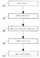
図6Aは本発明の実施形態に従う診断分析の方法を描くフローチャートである。ある実施形態において、生体内デバイスが使用される(例えば、自律的生体内デバイス、嚥下可能なカプセル、インプラントまたは同様のもの)。前記実施形態において方法の1つまたは一部または全ての操作が生体内で、および/または生体内デバイスが患者の体内にある間に実施されてもよい。ある実施形態において、例えば、1つまたは複数の操作が生体内で実施されてもよいとともに、1つまたは複数の操作がin vitroまたは生体外で実施されてもよい。 FIG. 6A is a flowchart depicting a method of diagnostic analysis according to an embodiment of the present invention. In certain embodiments, in-vivo devices are used (eg, autonomous in-vivo devices, swallowable capsules, implants or the like). In the above embodiments, one or some or all operations of the method may be performed in vivo and / or while the in vivo device is in the patient's body. In certain embodiments, for example, one or more operations may be performed in vivo, and one or more operations may be performed in vitro or in vitro.
ボックス502に示されるとおり、流体試料(例えば、GI管由来の試料)が生体内で収集または採取されてもよい。
As shown in
ボックス504に示されるとおり、生体内試料は第1の検出試薬と反応させて、例えば、試料中に存在すれば、マーカーの第1の検出試薬との結合を得てもよい。ある実施形態において、第1の検出試薬は標識されなくてもよいとともに、特定の場所、例えば、生体内感知または撮像デバイス内の反応チャンバに付着されてもよい。
As shown in
ボックス506に示されるとおり、典型的には標識された粒子は分析物および/またはマーカーと第1の検出試薬との化合物と反応させてもよい。これは、例えば、標識された粒子をマーカーと第1の検出試薬との典型的には固定化された化合物に結合することにより実施されてもよい。
As shown in
ボックス508に示されるとおり、標識された粒子のフラッシングまたは洗浄が洗浄溶液チャンバおよび廃棄チャンバのゲートを開門することにより実施されることで、過剰な非結合の標識された粒子が廃棄チャンバに流され得るようにしてもよい。
As shown in
ボックス510に示されるとおり、標識された粒子の固定化された化合物への結合が、例えば、標識を撮像またはさもなければ感知することにより検出され、それにより試料中のマーカーの存在および/または濃度が示されてもよい。
As shown in
ここで本発明の別の実施形態に従う分析方法を描くフローチャートを示す図6Bに参照がなされる。 Reference is now made to FIG. 6B which shows a flow chart depicting an analysis method according to another embodiment of the present invention.
ボックス602に示されるとおり、試料(例えば、GI管由来の試料)が生体内で収集または採取されてもよい。
As shown in
ボックス604に示されるとおり、試料は基質の光学特性を変化させる能力を有する分子と反応させてもよい。
As shown in
ボックス606に示されるとおり、抗体、または標的分析物用の他の結合分子が反応チャンバに固定化され得ることで、標的分析物は抗体に接着し得るとともにそれに装着される分子は分子−分析物含有試料が反応チャンバ22を通過するとき、本質的に反応チャンバに固定化されるであろう。
As shown in
ボックス608に示されるとおり、試料を伴う分子は反応チャンバへと流されてもよいとともに反応チャンバ22内の分子の集合が引き起こされてもよく、例えば、反応チャンバ内の光学的変化が、例えば、標識を撮像またはさもなければ感知することにより検出され、それにより試料中のマーカーの存在および/または濃度が示されてもよい。
As shown in
ボックス610に示されるとおり、光学的変化が、例えばイメージャによりキャプチャされる画像、光検出器の出力、または他の好適な手段により、検出されてもよい。in vitroの適用について光学的変化は人間の目により検出されてもよい。
As shown in
他の検出方法、例えば、磁場変化検出器を使用する磁性粒子の検出が使用されてもよい。他の好適な操作が使用されてもよい。 Other detection methods may be used, for example, detection of magnetic particles using a magnetic field change detector. Other suitable operations may be used.
図6Cは本発明の実施形態に従うin vitro分析方法を描くフローチャートである。ある実施形態において、方法の1つまたは一部または全ての操作がin vitro、生体外、患者の体外で、医師の診察室で、研究室で、または同様の場所で実施されてもよい。ある実施形態において、例えば、1つまたは複数の操作が生体内で実施されてもよいとともに、1つまたは複数の操作がin vitroまたは生体外で実施されてもよい。 FIG. 6C is a flowchart depicting an in vitro analysis method according to an embodiment of the present invention. In certain embodiments, one or some or all manipulations of the method may be performed in vitro, in vitro, outside the patient's body, in the doctor's office, in the laboratory, or in a similar location. In certain embodiments, for example, one or more operations may be performed in vivo, and one or more operations may be performed in vitro or in vitro.
ボックス712に示されるとおり、試料貯留器と試料採取チャンバとの間の第1のゲートが開門され、それにより試料が試料採取チャンバに引き込まれることが可能となってもよい。
As shown in
ボックス714に示されるとおり、試料採取チャンバと試料貯留器との間の第1のゲートが閉門され、それにより試料採取を停止する(例えば、試料の採取を終了する)とともに試料採取チャンバを試料貯留器から隔離してもよい。
As shown in
ボックス716に示されるとおり、試料採取チャンバと反応チャンバとの間の第2のゲートが開門され、例えば、試料が反応チャンバに移動することが可能になってもよい。
As shown in
他の実施形態において、記載され得たとおりの検出装置600Aおよび600および/または検出ユニット300、201、および200は、診断キット内に実装され、医師の診察研究室、緊急治療室向けに、または他の臨床適用において、in vitroで使用されてもよい。in vitro診断キットは典型的にはデータ、制御、および内部バッテリにより提供され得る電力の表示を提供する表示装置を含む机上用ハウジング型または携帯セットに収容されてもよい。
In other embodiments,
他の好適な操作または操作のセットが使用されてもよい。 Other suitable operations or sets of operations may be used.
本発明の特定の特徴が本明細書に説明および記載されてきたが、多くの変更、置換、変形、および均等物がここで当業者には考え付くであろう。それゆえ、添付の特許請求の範囲が本発明の真の趣旨の範囲内に入るように全てのかかる変更および変形を網羅することを意図していることは理解されるべきである。 While particular features of the invention have been illustrated and described herein, many modifications, substitutions, variations, and equivalents will now occur to those skilled in the art. Therefore, it is to be understood that the appended claims are intended to cover all such modifications and variations as fall within the true spirit of the invention.
Claims (97)
前記流体試料を生体内で取得するための入口、
検出試薬が前記流体試料中の前記分析物と反応する反応チャンバ、
廃棄チャンバ、
前記反応チャンバを前記廃棄チャンバに流体連通するゲート、
を含んでなる生体内デバイス。 An in vivo device for detecting the presence of an analyte in a fluid sample,
An inlet for obtaining the fluid sample in vivo;
A reaction chamber in which a detection reagent reacts with the analyte in the fluid sample;
Waste chamber,
A gate in fluid communication with the reaction chamber to the waste chamber;
An in vivo device comprising:
前記生体内流体試料を検出装置内に生体内で採取するステップであって、前記検出装置が、
前記流体試料を生体内で取得するための入口、
検出試薬が前記流体試料中の前記分析物と反応する反応チャンバ、
廃棄チャンバ、
前記反応チャンバを前記廃棄チャンバに流体連通するゲート、を含んでなるステップ、および
前記流体試料中の分析物と前記検出試薬との間の反応を検出するステップ、を含んでなる、方法。 A method for detecting the presence of an analyte in a biological fluid sample, the method comprising:
Collecting the in-vivo fluid sample in a detection apparatus in vivo, wherein the detection apparatus comprises:
An inlet for obtaining the fluid sample in vivo;
A reaction chamber in which a detection reagent reacts with the analyte in the fluid sample;
Waste chamber,
A gate comprising fluidly communicating the reaction chamber to the waste chamber, and detecting a reaction between an analyte in the fluid sample and the detection reagent.
流体試料を取得するための入口、
検出試薬が前記流体試料中の分析物と反応する反応チャンバ、
廃棄チャンバ、
前記反応チャンバを前記廃棄チャンバに流体連通するゲート、を含んでなるin vitro分析キット。 A disposable in vitro automated analysis kit,
An inlet for obtaining a fluid sample,
A reaction chamber in which a detection reagent reacts with an analyte in the fluid sample;
Waste chamber,
An in vitro analysis kit comprising a gate in fluid communication with the reaction chamber to the waste chamber.
背後に検出ユニット、イメージャおよび照明光源が配置される観察窓を含んでなり、前記検出ユニットが流体連通される反応チャンバおよび廃棄チャンバを含んでなる、カプセル。 An ingestible capsule,
A capsule comprising an observation window, behind which a detection unit, an imager and an illumination light source are arranged, the reaction unit comprising a reaction chamber and a waste chamber in fluid communication.
前記流体試料を生体内で取得するための入口、
検出試薬が前記流体試料中の前記分析物と反応する反応チャンバ、
廃棄チャンバ、
前記反応チャンバを前記廃棄チャンバに流体連通するゲート、
前記GI管および前記反応チャンバの一部分を撮像するためのイメージャ、および
画像データを伝送するための送信機、
を含んでなる、生体内カプセル、
外部受信機/記録デバイス、
ディスプレイユニットを備えた外部プロセッサ、を含んでなり、
前記外部プロセッサが前記GI管の画像および前記反応チャンバの前記部分の画像を表示するよう構成される、装置。 An apparatus for detecting the presence of an analyte in a fluid sample of a GI tract, comprising:
An inlet for obtaining the fluid sample in vivo;
A reaction chamber in which a detection reagent reacts with the analyte in the fluid sample;
Waste chamber,
A gate in fluid communication with the reaction chamber to the waste chamber;
An imager for imaging the GI tube and a portion of the reaction chamber; and a transmitter for transmitting image data;
An in vivo capsule comprising,
External receiver / recording device,
An external processor with a display unit,
The apparatus wherein the external processor is configured to display an image of the GI tract and an image of the portion of the reaction chamber.
Applications Claiming Priority (2)
| Application Number | Priority Date | Filing Date | Title |
|---|---|---|---|
| US64779005P | 2005-01-31 | 2005-01-31 | |
| PCT/IL2006/000127 WO2006080024A2 (en) | 2005-01-31 | 2006-01-31 | Device, system and method for in vivo analysis |
Publications (2)
| Publication Number | Publication Date |
|---|---|
| JP2008528170A true JP2008528170A (en) | 2008-07-31 |
| JP2008528170A5 JP2008528170A5 (en) | 2009-03-26 |
Family
ID=36740903
Family Applications (1)
| Application Number | Title | Priority Date | Filing Date |
|---|---|---|---|
| JP2007552809A Pending JP2008528170A (en) | 2005-01-31 | 2006-01-31 | In vivo analysis device, apparatus and method |
Country Status (5)
| Country | Link |
|---|---|
| US (1) | US8249681B2 (en) |
| EP (1) | EP1843697B1 (en) |
| JP (1) | JP2008528170A (en) |
| AT (1) | ATE538715T1 (en) |
| WO (1) | WO2006080024A2 (en) |
Cited By (7)
| Publication number | Priority date | Publication date | Assignee | Title |
|---|---|---|---|---|
| JP2013500466A (en) * | 2009-07-24 | 2013-01-07 | アコーニ バイオシステムズ | Flow cell device |
| JP2015021906A (en) * | 2013-07-22 | 2015-02-02 | 東亜ディーケーケー株式会社 | Measuring method, cartridge for measurement, and measuring device |
| JP2019023656A (en) * | 2013-03-11 | 2019-02-14 | キュー ヘルス インコーポレイテッド | System and method for detection and quantification of analyte |
| JP2020508436A (en) * | 2016-12-07 | 2020-03-19 | プロジェニティ, インコーポレイテッド | Gastrointestinal tract detection method, apparatus and system |
| USD909600S1 (en) | 2015-07-17 | 2021-02-02 | Cue Health Inc. | Sample collection device of an analyte detection system |
| US11237161B2 (en) | 2017-01-25 | 2022-02-01 | Cue Health Inc. | Systems and methods for enhanced detection and quantification of analytes |
| USD951789S1 (en) | 2014-05-12 | 2022-05-17 | Cue Health Inc. | Reader device for an analyte detection system |
Families Citing this family (24)
| Publication number | Priority date | Publication date | Assignee | Title |
|---|---|---|---|---|
| US8738106B2 (en) * | 2005-01-31 | 2014-05-27 | Given Imaging, Ltd | Device, system and method for in vivo analysis |
| EP1954197A2 (en) * | 2005-11-22 | 2008-08-13 | Stichting Top Institute Food and Nutrition | Sampling device for in vivo sampling of liquids from the gastrointestinal tract, process for the production thereof and mould or mask for use in the production process |
| EP2013795A2 (en) * | 2006-04-03 | 2009-01-14 | Given Imaging Ltd. | Device, system and method for in-vivo analysis |
| ATE531199T1 (en) * | 2006-04-03 | 2011-11-15 | Given Imaging Ltd | DEVICE, SYSTEM AND METHOD FOR IN VIVO ANALYSIS |
| CN101458249B (en) * | 2007-12-14 | 2013-09-11 | 东莞博识生物科技有限公司 | Microfluid example boat with solution storage chamber and pump structure |
| US8515507B2 (en) * | 2008-06-16 | 2013-08-20 | Given Imaging Ltd. | Device and method for detecting in-vivo pathology |
| EP2339951A1 (en) * | 2008-07-10 | 2011-07-06 | Given Imaging Ltd. | Device, method and kit for in vivo detection of a biomarker |
| AU2010209278B2 (en) | 2009-01-29 | 2014-10-23 | Given Imaging Ltd. | Device,system and method for detection of bleeding |
| US20100324365A1 (en) * | 2009-06-17 | 2010-12-23 | Daniel Victor Marquez | Diagnostic Capsule with Software that Triggers Imaging Equipment |
| JP5642373B2 (en) * | 2009-10-23 | 2014-12-17 | オリンパス株式会社 | Portable wireless terminal, wireless communication system, and wireless communication method for portable wireless terminal |
| KR101431368B1 (en) * | 2010-05-14 | 2014-08-19 | 사반치 유니버시티 | An apparatus for using hydrodynamic cavitation in medical treatment |
| EP2590558A4 (en) * | 2010-07-07 | 2013-11-27 | Therasyn Sensors Inc | A device and method for continuous chemical sensing |
| WO2012027048A2 (en) * | 2010-08-26 | 2012-03-01 | Jeanette Hill | Biological fluid sampling and storage apparatus for remote use |
| GB201018413D0 (en) | 2010-11-01 | 2010-12-15 | Univ Cardiff | In-vivo monitoring with microwaves |
| CN103827668B (en) * | 2011-08-04 | 2016-04-20 | 基文影像公司 | For device, the system and method for immunoassays in body |
| US20140323819A1 (en) * | 2013-04-29 | 2014-10-30 | Elwha LLC, a limited liability company of the State of Delaware | Multi-parameter test units for initial indication of medical symptoms |
| WO2015095853A1 (en) | 2013-12-20 | 2015-06-25 | Spot On Sciences, Inc. | Whole blood separation sampling apparatus |
| WO2016123616A1 (en) | 2015-01-30 | 2016-08-04 | Smiths Medical Asd, Inc. | Intravenous catheter assembly design |
| WO2016123620A1 (en) * | 2015-01-30 | 2016-08-04 | Smiths Medical Asd, Inc. | Needle assembly with diagnostic analysis provisions |
| CN105030183B (en) * | 2015-09-09 | 2016-11-16 | 京东方科技集团股份有限公司 | A kind of endoscope and medical detection system |
| US11931738B2 (en) | 2018-04-24 | 2024-03-19 | Hewlett-Packard Development Company, L.P. | Sequenced droplet ejection to deliver fluids |
| US11925932B2 (en) | 2018-04-24 | 2024-03-12 | Hewlett-Packard Development Company, L.P. | Microfluidic devices |
| WO2020018073A1 (en) | 2018-07-17 | 2020-01-23 | Hewlett-Packard Development Company, L.P. | Droplet ejectors with target media |
| WO2020018074A1 (en) | 2018-07-17 | 2020-01-23 | Hewlett-Packard Development Company, L.P. | Droplet ejectors to provide fluids to droplet ejectors |
Citations (11)
| Publication number | Priority date | Publication date | Assignee | Title |
|---|---|---|---|---|
| JPS5294681A (en) * | 1976-02-05 | 1977-08-09 | Seiko Instr & Electronics | Medical capsule |
| JPS57163309A (en) * | 1981-04-01 | 1982-10-07 | Olympus Optical Co Ltd | Capsule apparatus for medical use |
| JPS62240038A (en) * | 1986-04-14 | 1987-10-20 | 財団法人ライフテクノロジー研究所 | Medical capsule and its use |
| JPH04138128A (en) * | 1990-09-28 | 1992-05-12 | Shimadzu Corp | Gastric juice sampling device |
| JPH05200015A (en) * | 1991-03-14 | 1993-08-10 | Olympus Optical Co Ltd | Medical capsule device |
| JP2004523274A (en) * | 2001-01-16 | 2004-08-05 | ギブン・イメージング・リミテツド | Systems and methods for determining body cavity status in vivo |
| JP2004529733A (en) * | 2001-05-17 | 2004-09-30 | フェールグクレーマン・アクチボラゲット | Sampling device and method for obtaining a sample of a substance in the body and method for producing the sampling device |
| WO2004105946A2 (en) * | 2003-05-29 | 2004-12-09 | Bayer Healthcare Llc | Packaging of microfluidic devices |
| JP2004350512A (en) * | 2003-05-27 | 2004-12-16 | Tokai Univ | Sensing pump and sensor system using the same |
| WO2005003723A2 (en) * | 2003-06-27 | 2005-01-13 | Bayer Healthcare Llc | Method for uniform application of fluid into a reactive reagent area |
| WO2005084534A1 (en) * | 2003-09-03 | 2005-09-15 | Life Patch International, Inc. | Personal diagnostic devices and related methods |
Family Cites Families (7)
| Publication number | Priority date | Publication date | Assignee | Title |
|---|---|---|---|---|
| US5993378A (en) * | 1980-10-28 | 1999-11-30 | Lemelson; Jerome H. | Electro-optical instruments and methods for treating disease |
| US5856174A (en) | 1995-06-29 | 1999-01-05 | Affymetrix, Inc. | Integrated nucleic acid diagnostic device |
| JP4138128B2 (en) | 1999-01-26 | 2008-08-20 | 株式会社日立製作所 | Variable valve operating device for internal combustion engine |
| WO2001053792A2 (en) * | 2000-01-19 | 2001-07-26 | Given Imaging Ltd. | A system for detecting substances |
| US6766817B2 (en) | 2001-07-25 | 2004-07-27 | Tubarc Technologies, Llc | Fluid conduction utilizing a reversible unsaturated siphon with tubarc porosity action |
| WO2004014227A1 (en) | 2002-08-13 | 2004-02-19 | Given Imaging Ltd. | System for in vivo sampling and analysis |
| IL159113A (en) * | 2002-11-27 | 2008-11-26 | Given Imaging Ltd | Method and device of imaging with an imager having a fiber plate cover |
-
2006
- 2006-01-31 US US11/883,351 patent/US8249681B2/en active Active
- 2006-01-31 EP EP06701723A patent/EP1843697B1/en not_active Not-in-force
- 2006-01-31 JP JP2007552809A patent/JP2008528170A/en active Pending
- 2006-01-31 WO PCT/IL2006/000127 patent/WO2006080024A2/en active Application Filing
- 2006-01-31 AT AT06701723T patent/ATE538715T1/en active
Patent Citations (11)
| Publication number | Priority date | Publication date | Assignee | Title |
|---|---|---|---|---|
| JPS5294681A (en) * | 1976-02-05 | 1977-08-09 | Seiko Instr & Electronics | Medical capsule |
| JPS57163309A (en) * | 1981-04-01 | 1982-10-07 | Olympus Optical Co Ltd | Capsule apparatus for medical use |
| JPS62240038A (en) * | 1986-04-14 | 1987-10-20 | 財団法人ライフテクノロジー研究所 | Medical capsule and its use |
| JPH04138128A (en) * | 1990-09-28 | 1992-05-12 | Shimadzu Corp | Gastric juice sampling device |
| JPH05200015A (en) * | 1991-03-14 | 1993-08-10 | Olympus Optical Co Ltd | Medical capsule device |
| JP2004523274A (en) * | 2001-01-16 | 2004-08-05 | ギブン・イメージング・リミテツド | Systems and methods for determining body cavity status in vivo |
| JP2004529733A (en) * | 2001-05-17 | 2004-09-30 | フェールグクレーマン・アクチボラゲット | Sampling device and method for obtaining a sample of a substance in the body and method for producing the sampling device |
| JP2004350512A (en) * | 2003-05-27 | 2004-12-16 | Tokai Univ | Sensing pump and sensor system using the same |
| WO2004105946A2 (en) * | 2003-05-29 | 2004-12-09 | Bayer Healthcare Llc | Packaging of microfluidic devices |
| WO2005003723A2 (en) * | 2003-06-27 | 2005-01-13 | Bayer Healthcare Llc | Method for uniform application of fluid into a reactive reagent area |
| WO2005084534A1 (en) * | 2003-09-03 | 2005-09-15 | Life Patch International, Inc. | Personal diagnostic devices and related methods |
Cited By (13)
| Publication number | Priority date | Publication date | Assignee | Title |
|---|---|---|---|---|
| US8680026B2 (en) | 2008-05-09 | 2014-03-25 | Akonni Biosystems, Inc. | Flow cell device |
| JP2013500466A (en) * | 2009-07-24 | 2013-01-07 | アコーニ バイオシステムズ | Flow cell device |
| JP2019023656A (en) * | 2013-03-11 | 2019-02-14 | キュー ヘルス インコーポレイテッド | System and method for detection and quantification of analyte |
| US11845078B2 (en) | 2013-03-11 | 2023-12-19 | Cue Health Inc. | Systems and methods for detection and quantification of analytes |
| US11717822B2 (en) | 2013-03-11 | 2023-08-08 | Cue Health Inc. | System for portable and easy-to-use detection of analytes with mobile computing device |
| JP2015021906A (en) * | 2013-07-22 | 2015-02-02 | 東亜ディーケーケー株式会社 | Measuring method, cartridge for measurement, and measuring device |
| USD951789S1 (en) | 2014-05-12 | 2022-05-17 | Cue Health Inc. | Reader device for an analyte detection system |
| USD994516S1 (en) | 2014-05-12 | 2023-08-08 | Cue Health Inc. | Reader device for an analyte detection system |
| US11154866B2 (en) | 2015-07-17 | 2021-10-26 | Cue Health Inc. | Systems and methods for facilitating fluid flow during enhanced detection and quantification of analytes |
| US11059045B2 (en) | 2015-07-17 | 2021-07-13 | Cue Health Inc. | Cartridges, kits, and methods for enhanced detection and quantification of analytes |
| USD909600S1 (en) | 2015-07-17 | 2021-02-02 | Cue Health Inc. | Sample collection device of an analyte detection system |
| JP2020508436A (en) * | 2016-12-07 | 2020-03-19 | プロジェニティ, インコーポレイテッド | Gastrointestinal tract detection method, apparatus and system |
| US11237161B2 (en) | 2017-01-25 | 2022-02-01 | Cue Health Inc. | Systems and methods for enhanced detection and quantification of analytes |
Also Published As
| Publication number | Publication date |
|---|---|
| US20080114225A1 (en) | 2008-05-15 |
| WO2006080024A2 (en) | 2006-08-03 |
| US8249681B2 (en) | 2012-08-21 |
| EP1843697B1 (en) | 2011-12-28 |
| EP1843697A2 (en) | 2007-10-17 |
| ATE538715T1 (en) | 2012-01-15 |
| EP1843697A4 (en) | 2010-01-20 |
| WO2006080024A3 (en) | 2007-01-25 |
Similar Documents
| Publication | Publication Date | Title |
|---|---|---|
| US8249681B2 (en) | Device, system and method for in vivo analysis | |
| US8738106B2 (en) | Device, system and method for in vivo analysis | |
| CN103827668B (en) | For device, the system and method for immunoassays in body | |
| EP1534120B1 (en) | System for in vivo sampling and analysis | |
| US20090216082A1 (en) | Device, System and Method for In Vivo Magnetic Immunoassay Analysis | |
| JP4709836B2 (en) | Autonomous internal device | |
| US7938775B2 (en) | Device, system, and method for in-vivo analysis | |
| US10827953B2 (en) | Devices, systems and methods for in-vivo immunoassay | |
| US8663093B2 (en) | Device, system and method for in-vivo analysis | |
| US10794902B2 (en) | Digital control of on-chip magnetic particle assay | |
| CN100471447C (en) | Lesion detecting system | |
| US20130237774A1 (en) | Device and Method for Continuous Chemical Sensing | |
| JP5275217B2 (en) | Systems for in vivo analysis | |
| WO2009057120A2 (en) | Device, system and method for in-vivo analysis | |
| WO1999044066A1 (en) | Encapsulated diagnostics for alimentary analytes | |
| JP4481696B2 (en) | In-vivo information acquisition system | |
| IL194468A (en) | In-vivo imaging device | |
| IL205462A (en) | Device, system and method for in-vivo analysis |
Legal Events
| Date | Code | Title | Description |
|---|---|---|---|
| A521 | Request for written amendment filed |
Free format text: JAPANESE INTERMEDIATE CODE: A523 Effective date: 20090130 |
|
| A621 | Written request for application examination |
Free format text: JAPANESE INTERMEDIATE CODE: A621 Effective date: 20090130 |
|
| RD02 | Notification of acceptance of power of attorney |
Free format text: JAPANESE INTERMEDIATE CODE: A7422 Effective date: 20110404 |
|
| RD04 | Notification of resignation of power of attorney |
Free format text: JAPANESE INTERMEDIATE CODE: A7424 Effective date: 20110406 |
|
| A521 | Request for written amendment filed |
Free format text: JAPANESE INTERMEDIATE CODE: A821 Effective date: 20110404 |
|
| A977 | Report on retrieval |
Free format text: JAPANESE INTERMEDIATE CODE: A971007 Effective date: 20110518 |
|
| A521 | Request for written amendment filed |
Free format text: JAPANESE INTERMEDIATE CODE: A523 Effective date: 20110517 |
|
| A131 | Notification of reasons for refusal |
Free format text: JAPANESE INTERMEDIATE CODE: A131 Effective date: 20110621 |
|
| A601 | Written request for extension of time |
Free format text: JAPANESE INTERMEDIATE CODE: A601 Effective date: 20110916 |
|
| A602 | Written permission of extension of time |
Free format text: JAPANESE INTERMEDIATE CODE: A602 Effective date: 20110927 |
|
| A521 | Request for written amendment filed |
Free format text: JAPANESE INTERMEDIATE CODE: A523 Effective date: 20111220 |
|
| A02 | Decision of refusal |
Free format text: JAPANESE INTERMEDIATE CODE: A02 Effective date: 20120124 |
|
| A601 | Written request for extension of time |
Free format text: JAPANESE INTERMEDIATE CODE: A601 Effective date: 20130624 |
|
| A602 | Written permission of extension of time |
Free format text: JAPANESE INTERMEDIATE CODE: A602 Effective date: 20130627 |
|
| A521 | Request for written amendment filed |
Free format text: JAPANESE INTERMEDIATE CODE: A523 Effective date: 20130925 |