JP2008525108A - Inhalation device - Google Patents
Inhalation device Download PDFInfo
- Publication number
- JP2008525108A JP2008525108A JP2007548287A JP2007548287A JP2008525108A JP 2008525108 A JP2008525108 A JP 2008525108A JP 2007548287 A JP2007548287 A JP 2007548287A JP 2007548287 A JP2007548287 A JP 2007548287A JP 2008525108 A JP2008525108 A JP 2008525108A
- Authority
- JP
- Japan
- Prior art keywords
- container
- inhalation device
- active ingredient
- inhalation
- firing
- Prior art date
- Legal status (The legal status is an assumption and is not a legal conclusion. Google has not performed a legal analysis and makes no representation as to the accuracy of the status listed.)
- Pending
Links
Images


Classifications
-
- A—HUMAN NECESSITIES
- A61—MEDICAL OR VETERINARY SCIENCE; HYGIENE
- A61M—DEVICES FOR INTRODUCING MEDIA INTO, OR ONTO, THE BODY; DEVICES FOR TRANSDUCING BODY MEDIA OR FOR TAKING MEDIA FROM THE BODY; DEVICES FOR PRODUCING OR ENDING SLEEP OR STUPOR
- A61M15/00—Inhalators
- A61M15/0028—Inhalators using prepacked dosages, one for each application, e.g. capsules to be perforated or broken-up
- A61M15/0045—Inhalators using prepacked dosages, one for each application, e.g. capsules to be perforated or broken-up using multiple prepacked dosages on a same carrier, e.g. blisters
-
- A—HUMAN NECESSITIES
- A61—MEDICAL OR VETERINARY SCIENCE; HYGIENE
- A61M—DEVICES FOR INTRODUCING MEDIA INTO, OR ONTO, THE BODY; DEVICES FOR TRANSDUCING BODY MEDIA OR FOR TAKING MEDIA FROM THE BODY; DEVICES FOR PRODUCING OR ENDING SLEEP OR STUPOR
- A61M15/00—Inhalators
- A61M15/0001—Details of inhalators; Constructional features thereof
- A61M15/0003—Details of inhalators; Constructional features thereof with means for dispensing more than one drug
-
- A—HUMAN NECESSITIES
- A61—MEDICAL OR VETERINARY SCIENCE; HYGIENE
- A61M—DEVICES FOR INTRODUCING MEDIA INTO, OR ONTO, THE BODY; DEVICES FOR TRANSDUCING BODY MEDIA OR FOR TAKING MEDIA FROM THE BODY; DEVICES FOR PRODUCING OR ENDING SLEEP OR STUPOR
- A61M15/00—Inhalators
- A61M15/0001—Details of inhalators; Constructional features thereof
- A61M15/0021—Mouthpieces therefor
- A61M15/0025—Mouthpieces therefor with caps
- A61M15/0026—Hinged caps
-
- A—HUMAN NECESSITIES
- A61—MEDICAL OR VETERINARY SCIENCE; HYGIENE
- A61M—DEVICES FOR INTRODUCING MEDIA INTO, OR ONTO, THE BODY; DEVICES FOR TRANSDUCING BODY MEDIA OR FOR TAKING MEDIA FROM THE BODY; DEVICES FOR PRODUCING OR ENDING SLEEP OR STUPOR
- A61M15/00—Inhalators
- A61M15/0028—Inhalators using prepacked dosages, one for each application, e.g. capsules to be perforated or broken-up
- A61M15/003—Inhalators using prepacked dosages, one for each application, e.g. capsules to be perforated or broken-up using capsules, e.g. to be perforated or broken-up
- A61M15/0033—Details of the piercing or cutting means
-
- A—HUMAN NECESSITIES
- A61—MEDICAL OR VETERINARY SCIENCE; HYGIENE
- A61M—DEVICES FOR INTRODUCING MEDIA INTO, OR ONTO, THE BODY; DEVICES FOR TRANSDUCING BODY MEDIA OR FOR TAKING MEDIA FROM THE BODY; DEVICES FOR PRODUCING OR ENDING SLEEP OR STUPOR
- A61M15/00—Inhalators
- A61M15/0028—Inhalators using prepacked dosages, one for each application, e.g. capsules to be perforated or broken-up
- A61M15/0045—Inhalators using prepacked dosages, one for each application, e.g. capsules to be perforated or broken-up using multiple prepacked dosages on a same carrier, e.g. blisters
- A61M15/0046—Inhalators using prepacked dosages, one for each application, e.g. capsules to be perforated or broken-up using multiple prepacked dosages on a same carrier, e.g. blisters characterized by the type of carrier
- A61M15/005—Inhalators using prepacked dosages, one for each application, e.g. capsules to be perforated or broken-up using multiple prepacked dosages on a same carrier, e.g. blisters characterized by the type of carrier the dosages being arranged on a cylindrical surface
-
- A—HUMAN NECESSITIES
- A61—MEDICAL OR VETERINARY SCIENCE; HYGIENE
- A61M—DEVICES FOR INTRODUCING MEDIA INTO, OR ONTO, THE BODY; DEVICES FOR TRANSDUCING BODY MEDIA OR FOR TAKING MEDIA FROM THE BODY; DEVICES FOR PRODUCING OR ENDING SLEEP OR STUPOR
- A61M15/00—Inhalators
- A61M15/0028—Inhalators using prepacked dosages, one for each application, e.g. capsules to be perforated or broken-up
- A61M15/0045—Inhalators using prepacked dosages, one for each application, e.g. capsules to be perforated or broken-up using multiple prepacked dosages on a same carrier, e.g. blisters
- A61M15/0046—Inhalators using prepacked dosages, one for each application, e.g. capsules to be perforated or broken-up using multiple prepacked dosages on a same carrier, e.g. blisters characterized by the type of carrier
- A61M15/0051—Inhalators using prepacked dosages, one for each application, e.g. capsules to be perforated or broken-up using multiple prepacked dosages on a same carrier, e.g. blisters characterized by the type of carrier the dosages being arranged on a tape, e.g. strips
-
- A—HUMAN NECESSITIES
- A61—MEDICAL OR VETERINARY SCIENCE; HYGIENE
- A61M—DEVICES FOR INTRODUCING MEDIA INTO, OR ONTO, THE BODY; DEVICES FOR TRANSDUCING BODY MEDIA OR FOR TAKING MEDIA FROM THE BODY; DEVICES FOR PRODUCING OR ENDING SLEEP OR STUPOR
- A61M15/00—Inhalators
- A61M15/0065—Inhalators with dosage or measuring devices
- A61M15/0068—Indicating or counting the number of dispensed doses or of remaining doses
- A61M15/007—Mechanical counters
- A61M15/0071—Mechanical counters having a display or indicator
- A61M15/0075—Mechanical counters having a display or indicator on a disc
-
- A—HUMAN NECESSITIES
- A61—MEDICAL OR VETERINARY SCIENCE; HYGIENE
- A61M—DEVICES FOR INTRODUCING MEDIA INTO, OR ONTO, THE BODY; DEVICES FOR TRANSDUCING BODY MEDIA OR FOR TAKING MEDIA FROM THE BODY; DEVICES FOR PRODUCING OR ENDING SLEEP OR STUPOR
- A61M15/00—Inhalators
- A61M15/0091—Inhalators mechanically breath-triggered
- A61M15/0096—Hindering inhalation before activation of the dispenser
-
- A—HUMAN NECESSITIES
- A61—MEDICAL OR VETERINARY SCIENCE; HYGIENE
- A61M—DEVICES FOR INTRODUCING MEDIA INTO, OR ONTO, THE BODY; DEVICES FOR TRANSDUCING BODY MEDIA OR FOR TAKING MEDIA FROM THE BODY; DEVICES FOR PRODUCING OR ENDING SLEEP OR STUPOR
- A61M2205/00—General characteristics of the apparatus
- A61M2205/58—Means for facilitating use, e.g. by people with impaired vision
- A61M2205/581—Means for facilitating use, e.g. by people with impaired vision by audible feedback
-
- A—HUMAN NECESSITIES
- A61—MEDICAL OR VETERINARY SCIENCE; HYGIENE
- A61M—DEVICES FOR INTRODUCING MEDIA INTO, OR ONTO, THE BODY; DEVICES FOR TRANSDUCING BODY MEDIA OR FOR TAKING MEDIA FROM THE BODY; DEVICES FOR PRODUCING OR ENDING SLEEP OR STUPOR
- A61M2205/00—General characteristics of the apparatus
- A61M2205/58—Means for facilitating use, e.g. by people with impaired vision
- A61M2205/582—Means for facilitating use, e.g. by people with impaired vision by tactile feedback
-
- A—HUMAN NECESSITIES
- A61—MEDICAL OR VETERINARY SCIENCE; HYGIENE
- A61M—DEVICES FOR INTRODUCING MEDIA INTO, OR ONTO, THE BODY; DEVICES FOR TRANSDUCING BODY MEDIA OR FOR TAKING MEDIA FROM THE BODY; DEVICES FOR PRODUCING OR ENDING SLEEP OR STUPOR
- A61M2205/00—General characteristics of the apparatus
- A61M2205/82—Internal energy supply devices
- A61M2205/8218—Gas operated
Abstract
2つ以上の気密シール容器(39)を備える吸入デバイス(1)であって、各容器が、薬学的に有効な成分、および、HFA134a、HFA227、又はこれらの混合物からなる液化エーロゾル噴射剤を含む加圧製剤の1回用量を収容し、各容器の少なくとも一部(39a)が穿孔可能である吸入デバイス(1)。 An inhalation device (1) comprising two or more hermetically sealed containers (39), each container comprising a pharmaceutically active ingredient and a liquefied aerosol propellant comprising HFA 134a, HFA 227, or a mixture thereof An inhalation device (1) that contains a single dose of a pressurized formulation and at least a portion (39a) of each container is piercable.
Description
本発明は、全般に、それぞれが加圧液化噴射剤をベースにする製剤の予め計量された1回用量を保持する、2個以上の気密シール容器を備える吸入デバイスに関する。 The present invention relates generally to inhalation devices comprising two or more hermetically sealed containers, each holding a pre-metered single dose of a formulation based on a pressurized liquefied propellant.
加圧定量吸入器は、喘息および他の呼吸器症状の治療に40年以上の間使用されてきた。加圧定量吸入器は、噴射剤をベースにする製剤の多数回の用量が充填されている容器と共に、要求に応じて個々の計量された用量を分配するための計量弁を備える。慣用的な定量吸入器の欠点の1つは、幾つかの治療処方計画に適切な少数回(例えば、30未満)の用量を提供するのが困難なことである。更に、製剤の個々の用量を提供することがある乾燥粉末吸入デバイス又は液体経鼻的デバイスが市販されており、二酸化炭素、酸素又は窒素などのガスを含む1回用量吸入デバイスが提案されてきた(1979年に公開された米国特許第4,137,914号明細書を参照)が、今日まで、個々の予め計量された加圧用量を提供する商業的に実現可能な吸入デバイスは提案又は商業化されていない。 Pressurized metered dose inhalers have been used for over 40 years to treat asthma and other respiratory symptoms. Pressurized metered dose inhalers are equipped with a metering valve for dispensing individual metered doses as required, with containers filled with multiple doses of propellant-based formulations. One disadvantage of conventional metered dose inhalers is that it is difficult to provide a few (eg, less than 30) doses that are appropriate for some treatment regimens. In addition, dry powder inhalation devices or liquid nasal devices that may provide individual doses of the formulation are commercially available, and single dose inhalation devices containing gases such as carbon dioxide, oxygen or nitrogen have been proposed (See US Pat. No. 4,137,914 published in 1979), to date, commercially feasible inhalation devices that provide individual pre-metered pressurized doses have been proposed or commercialized. It has not been converted.
薬学的に有効な成分を肺に送達するのに好適な、個々の予め計量された加圧用量を具備する商業的に実現可能な吸入デバイスを提供する必要がある。 There is a need to provide a commercially viable inhalation device with individual pre-metered pressurized doses suitable for delivering pharmaceutically active ingredients to the lung.
それぞれが薬学的に有効な成分、および、1,1,1,2−テトラフルオロエタン(HFA134a)、1,1,1,2,3,3,3−ヘプタフルオロプロパン(HFA227)、又はこれらの混合物からなる液化エーロゾル噴射剤を(唯一の噴射剤成分として)含む加圧製剤の1回用量を収容する気密シール容器であって、容器の少なくとも一部が穿孔可能である(即ち、穿孔されることができる)気密シール容器を使用することにより、デバイスの作動時に、従って容器の穿孔時にエーロゾルが発生し、薬学的に有効な成分を肺に送達することを可能にする吸入デバイスが提供されることが分かった。更に、発生した吸入用のエーロゾルは、有利には、液化噴射剤と共に薬学的に有効な成分の微細な液滴を含み、有効成分を患者の肺に確実に送達し搬送することを可能にする。 Each pharmaceutically active ingredient and 1,1,1,2-tetrafluoroethane (HFA134a), 1,1,1,2,3,3,3-heptafluoropropane (HFA227), or these A hermetically sealed container containing a single dose of a pressurized formulation comprising a liquefied aerosol propellant comprising a mixture (as the sole propellant component), wherein at least a portion of the container is piercable (ie, pierced) The use of a hermetically sealed container can provide an inhalation device that can generate an aerosol upon operation of the device, and thus upon puncture of the container, to deliver a pharmaceutically active ingredient to the lung. I understood that. Further, the generated inhalation aerosol advantageously comprises fine droplets of the pharmaceutically active ingredient together with the liquefied propellant, allowing the active ingredient to be reliably delivered and delivered to the patient's lungs. .
従って、本発明は、それぞれが薬学的に有効な成分、および、HFA134a、HFA227、又はこれらの混合物からなる液化エーロゾル噴射剤を含む加圧製剤の1回用量を収容する2個以上の気密シール容器を備え、各容器の少なくとも一部が穿孔可能である吸入デバイスを提供する。 Accordingly, the present invention provides two or more hermetically sealed containers each containing a single dose of a pharmaceutically active ingredient and a pressurized formulation comprising a liquefied aerosol propellant comprising HFA 134a, HFA 227, or a mixture thereof. An inhalation device in which at least a portion of each container is pierceable.
例えば、二酸化炭素、酸素、又は窒素などの圧縮ガスを含む、以前提案された加圧1回用量デバイス(米国特許第4,137,914号明細書および米国特許第6,062,213号明細書を参照)では、前記システムの作動(又は始動)時に、ガスは直ぐに気化し、従って、有効成分だけを有する「ハード型の(hard)」エーロゾルが発生し、デバイスは薬剤の肺への、又はその適正な分量の送達に適していない。米国特許第4,137,914号明細書に提案されているデバイスでは、薬剤の多くは、単にマウスピースの内面に堆積する(閉塞前、実際にその用量が開示されている毛細管を通過できる場合)ことが分かった。米国特許第6,062,213号明細書に開示されているデバイスでは、始動時に前賦活(proactive)送達手段が完全に気化する(有効成分だけを有するハード型のエーロゾルを提供する)ように、デバイスに室温で十分に高い蒸気圧が提供され、米国特許第4,137,914号明細書に提案されているデバイスと同様に、薬剤の多くは、単にデバイスの表面に直ぐに堆積する、および/又はデバイス内に保持される。 For example, previously proposed pressurized single dose devices (eg, US Pat. No. 4,137,914 and US Pat. No. 6,062,213) containing compressed gases such as carbon dioxide, oxygen, or nitrogen. )), Upon operation (or start-up) of the system, the gas immediately evaporates, thus generating a “hard” aerosol with only the active ingredient, and the device enters the lungs of the drug, or It is not suitable for delivery of the proper amount. In the device proposed in U.S. Pat. No. 4,137,914, much of the drug is simply deposited on the inner surface of the mouthpiece (if the dose can actually pass through the capillaries disclosed). ) In the device disclosed in US Pat. No. 6,062,213, so that the proactive delivery means is completely vaporized at startup (providing a hard aerosol with only the active ingredient) The device is provided with a sufficiently high vapor pressure at room temperature, and like the device proposed in US Pat. No. 4,137,914, much of the drug simply deposits immediately on the surface of the device, and / or Or held in the device.
本明細書に記載されるデバイスの容器は、好ましくは、周囲温度(22℃)で容器内の内部圧力が比較的低い、例えば、高くとも絶対圧力で7気圧である。これは、容器の形状が回転楕円体(内部圧力が高い容器に典型的には必要な形態)である必要がないという点で、とりわけ費用効果および製造の容易さに関して有利である。また、容器の内容積は、望ましくは0.3ml未満である。加圧製剤の容積は、典型的には、厚くとも150μlである。 The container of the device described herein preferably has a relatively low internal pressure in the container at ambient temperature (22 ° C.), for example, at most 7 atm absolute pressure. This is particularly advantageous with respect to cost effectiveness and ease of manufacture in that the shape of the container need not be a spheroid (typically required for containers with high internal pressure). The inner volume of the container is desirably less than 0.3 ml. The volume of the pressurized formulation is typically at most 150 μl.
本発明によるデバイスは、好ましくは、容器を穿孔するための撃針、より好ましくは2つ以上の撃針を更に備え、ここで、各容器は撃針と連動している。換言すれば、好ましい実施形態では、デバイスは、各容器がそれ自体の連動する撃針と関連するように、容器の数に対応する数の撃針を具備する。このことは、各容器の穿孔に新しい撃針が使用され、従って、1本の撃針を繰り返し使用する時に起こり得る鈍化および/又は閉塞のあらゆる問題が回避され得るという点で有利である。また、1回使用の撃針の使用により、本明細書に記載されるデバイスを、より好ましい構成および材料選択を考慮することによって、より効率的且つ効果的に製造することができる。各撃針は、両端に開口部を有するチャネルを備え、より望ましくは、チャネルは撃針の内面によって画成される。また、好都合には、容器の少なくとも穿孔可能な部分は、容器の穿孔に使用される撃針の撓み又は滑りを回避することを助けるように、実質的に平面状の部分として設けられてもよい。穿孔中の望ましくないエーロゾルの漏れを回避するため又は最小限にするため、このような穿孔は、好ましくは迅速である。特に、容器を穿孔する確実で迅速な発射力(患者によって提供されるあらゆる力と無関係)を提供するため、デバイスの作動時に、発射される容器(receptacle to−be−fired)と撃針は、望ましくは、作動時に解放されて、場合によっては容器および/又は撃針に作用する起動機構の使用により相互に移動し、その結果、撃針が容器の前記少なくとも穿孔可能な部分を穿孔し、エーロゾル製剤が前記チャネルをチャネルの第1の端部から第2の端部まで通過して患者に到達する。「相互に移動」の用語は、容器が撃針の方に移動する、又は撃針が容器の方に移動する、又は容器と撃針の両方が互いの方に移動することを意味する。作動中の撃針の撓み又は撃針の滑りを回避するため、好ましくは作動時に撃針は固定保持されており、例えば、作動時に解放されて容器に作用し、それを撃針の方に移動させる機械的に又は空気力学的に負荷されるインパクタを具備する起動機構の使用により、発射される容器が撃針の方に移動し、その結果、撃針が容器の前記少なくとも穿孔可能な部分を穿孔する。撃針で容器の前記少なくとも穿孔可能な部分が穿孔される時、撃針のチャネルの第1の端部が加圧製剤の液体部分に入るように、デバイスが構成されていることが好ましい。一時的な封止を促進するため、および/又は穿孔時に撃針と容器の間の望ましくない漏れを最小限にするため、容器に入る撃針の部分(例えば、その先端)の外面の形状が円錐状であることが有利な場合がある。 The device according to the invention preferably further comprises a firing needle for piercing the container, more preferably two or more firing needles, wherein each container is associated with a firing needle. In other words, in a preferred embodiment, the device comprises a number of firing pins corresponding to the number of containers so that each container is associated with its own interlocking firing needle. This is advantageous in that a new firing needle is used to pierce each container, and thus any problems of blunting and / or blockage that can occur when using a single firing needle are repeated. Also, with the use of a single use firing pin, the devices described herein can be more efficiently and effectively manufactured by considering more preferred configurations and material selections. Each firing pin includes a channel having openings at both ends, and more desirably, the channel is defined by the inner surface of the firing pin. Also advantageously, at least the pierceable portion of the container may be provided as a substantially planar portion to help avoid deflection or slipping of the firing pin used to pierce the container. Such perforations are preferably rapid in order to avoid or minimize unwanted aerosol leakage during the perforations. In particular, to provide a reliable and rapid firing force (regardless of any force provided by the patient) that pierces the container, the receptacle to-be-fired and firing pin are desirable during device operation. Are released upon actuation and, in some cases, move relative to each other by use of an actuating mechanism acting on the container and / or the shooter, so that the shooter pierces the at least pierceable portion of the container and the aerosol formulation is The channel is passed from the first end of the channel to the second end to reach the patient. The term “move relative to” means that the container moves toward the firing needle, or the firing needle moves toward the container, or both the container and the firing needle move toward each other. To avoid deflection of the firing pin or sliding of the firing pin during operation, the firing pin is preferably held stationary during operation, for example, mechanically released during operation to act on the container and move it towards the firing pin. Alternatively, the use of an activation mechanism comprising an aerodynamically loaded impactor moves the fired container towards the firing pin so that the firing needle punctures the at least pierceable portion of the container. The device is preferably configured such that when the at least the pierceable portion of the container is pierced with a firing pin, the first end of the channel of the firing needle enters the liquid portion of the pressurized formulation. To facilitate temporary sealing and / or to minimize undesirable leakage between the firing pin and the container during drilling, the outer surface of the portion of the firing needle that enters the container (eg, its tip) is conical. May be advantageous.
撃針のチャネル内の閉塞を最小限にするため、チャネルは、好ましくは毛細管の形態に設けられない。前記撃針チャネルの内面は膨張チャンバ、即ち、穿孔された容器からエーロゾルが放出された後、スプレー微粒化(spray break−up)オリフィスなどのより制限された部位を後で通過する前に、膨張するエーロゾルが通過するチャンバを提供するように構成されてもよい。閉塞の可能性を更に最小限にするため、前記チャネルの内面は、有利には、第1の端部から第2の端部まで略円錐状になっていてもよい。望ましくは、撃針のチャネルは、概ね単軸に沿って延びる。典型的には、撃針の最外部表面(例えば、撃針の先端の最外部部分)に、容器の少なくとも穿孔可能な部分を穿孔できる穿刺器が設けられている。撃針の変形によって起こる望ましくないチャネルの閉塞、および/又は、穿孔時の望ましくないエーロゾルの漏れを回避するために又は最小限にするために、チャネルの入口を撃針の前記最外部表面から僅かに偏らせることが有利であると分かった。従って、好ましい実施形態では、撃針のチャネルの第1の端部は、前記最外部表面から後退し、前記穿刺器に隣接して位置決めされている。 In order to minimize blockage in the firing channel, the channel is preferably not provided in the form of a capillary. The inner surface of the firing channel expands after the aerosol is released from the expanded chamber, i.e., the pierced container, and then later passes through a more limited site such as a spray break-up orifice. It may be configured to provide a chamber through which the aerosol passes. In order to further minimize the possibility of blockage, the inner surface of the channel may advantageously be generally conical from the first end to the second end. Desirably, the firing channel extends generally along a single axis. Typically, a puncture device is provided on the outermost surface of the firing needle (eg, the outermost portion of the tip of the firing needle) that can pierce at least the pierceable portion of the container. To avoid or minimize undesired channel occlusion and / or undesired aerosol leakage during drilling, the channel inlet is slightly offset from the outermost surface of the firing pin. It turned out to be advantageous. Thus, in a preferred embodiment, the first end of the firing channel is retracted from the outermost surface and positioned adjacent to the puncture device.
本明細書に記載されるデバイスは、望ましくはキャリヤを更に備え、キャリヤに容器が取り付けられている。キャリヤは回転式コンベヤ(carousel)の形態であってもよく、容器は、各容器の少なくとも穿孔可能な部分が半径方向外向きに位置決めされるように回転式コンベヤに取り付けられている。好都合には、容器と連動する撃針を具備する実施形態では、撃針は、また、例えば、各個々の撃針のチャネルの第1の端部がその関連する容器の少なくとも穿孔可能な部分の方に位置決めされるように、キャリヤに取り付けられてもよい。デバイスに新しい容器(および、好ましい実施形態では、その関連する撃針)を再充填するため、キャリヤと取り付けられている容器(および、好ましい実施形態では、その関連する撃針)を備えるデバイスの一部は、有利には、デバイスから可逆的に取り外し可能であってもよい。この部分は、好適にはカセットの形態で提供されてもよい。好都合には、本明細書に記載されるデバイスは、本体部分、および、容器(および、好ましい実施形態では、その関連する撃針)を具備するカセット、および、任意に取り替え用のカセットとして1つ以上のこのようなカセットを備える部品のキットの形態で提供されてもよい。 The devices described herein desirably further comprise a carrier with a container attached to the carrier. The carrier may be in the form of a carousel, and the containers are attached to the carousel so that at least the pierceable portion of each container is positioned radially outward. Conveniently, in embodiments comprising a firing pin in conjunction with a container, the firing needle is also positioned, for example, with the first end of the channel of each individual firing needle towards at least the pierceable portion of its associated container. As may be attached to the carrier. To refill the device with a new container (and in its preferred embodiment, its associated firing needle), a portion of the device comprising the container (and its associated firing needle in the preferred embodiment) attached to the carrier is Advantageously, it may be reversibly removable from the device. This part may preferably be provided in the form of a cassette. Conveniently, the devices described herein may include one or more cassettes comprising a body portion and a container (and, in a preferred embodiment, its associated firing needle), and optionally a replacement cassette. May be provided in the form of a kit of parts comprising such a cassette.
本明細書に記載されるデバイスは、好適には、通路を有し、患者の口又は鼻(一方若しくは両方の鼻孔)に挿入されるように適合した患者側出口を更に備える。本明細書に記載されるデバイスは、望ましくは、前進機構、特に機械的前進機構を更に備え、ここで、前進機構は、デバイスの作動前に、発射される容器(および、好ましい実施形態では、その関連する撃針)が、作動に備えて患者側出口と整列した位置合わせの位置まで前進するように構成され、より望ましくは、前進機構は、前の前進した容器が作動される(即ち、発射される)まで、後の容器が位置合わせの位置に前進することを防止するように構成されている。有利には、デバイスは患者側出口カバーを更に備え、カバーの開放時に、発射される容器(および、好ましい実施形態では、その関連する撃針)が位置合わせの位置まで前進するように、前記カバーは前進機構に連結されており、より詳細には、出口カバーの開放時に位置合わせの位置まで前進した容器が作動されなかった(即ち、発射された)場合、出口カバーの閉鎖時に前記容器(および、該当する場合、その関連する撃針)が前進する前の位置に戻り、そのためカバーが後で開放されるとき前記容器が(該当する場合、その関連する撃針と共に)再び位置合わせの位置まで前進するように、このようなカバーは前進機構に連結されている。本明細書では、好ましくは撃針および本明細書に記載される起動機構を使用して容器を穿孔し、その結果、エーロゾル製剤が容器から出て患者に到達するようにすることを、全般に、省略して、容器の作動又は容器の発射と称する。 The devices described herein preferably further comprise a patient outlet having a passageway and adapted to be inserted into the patient's mouth or nose (one or both nostrils). The devices described herein desirably further comprise an advancement mechanism, particularly a mechanical advancement mechanism, wherein the advancement mechanism is a container that is fired (and in preferred embodiments, prior to operation of the device). The associated firing needle) is configured to advance to an alignment position aligned with the patient outlet for operation, and more preferably, the advancement mechanism activates the previously advanced container (ie, firing). Until the container is advanced to the alignment position. Advantageously, the device further comprises a patient outlet cover, said cover being advanced so that when the cover is opened, the fired container (and in its preferred embodiment its associated firing pin) is advanced to the alignment position. Connected to the advancing mechanism, and more particularly, if the container that has been advanced to the alignment position when the outlet cover is opened is not actuated (i.e., fired), the container (and When applicable, the container (with its associated firing pin) returns to the position before advancement, so that when the cover is later opened, the container (with the associated firing needle, if applicable) is advanced again to the alignment position. In addition, such a cover is connected to the advance mechanism. As used herein, preferably, using a firing pin and the activation mechanism described herein to pierce the container so that the aerosol formulation exits the container and reaches the patient. Omitted and referred to as container actuation or container firing.
本明細書に記載されるデバイスは、手動で(例えば、ボタン又はレバーを押すことによって)作動されても、又は吸入によって(即ち、呼吸作動によって)作動されてもよい。呼吸作動が好ましい。例えば、全身性の疾患の治療のために薬学的に有効な成分を送達するには、エーロゾルが肺深部(例えば、肺胞部位)に浸透することを必要とする傾向がある。これには、用量放出を患者の吸気操作の初期部分とよく協調させる必要がある。呼吸作動は、特に吸入器を初めて使用する患者について、又は、吸入器を稀にしか使用しない患者について、必ずこのように協調させる確実な方法を提供する。 The devices described herein may be actuated manually (eg, by pressing a button or lever) or by inhalation (ie, by breathing actuation). Respiratory actuation is preferred. For example, delivery of pharmaceutically active ingredients for the treatment of systemic diseases tends to require the aerosol to penetrate deep into the lung (eg, alveolar sites). This requires the dose release to be well coordinated with the initial part of the patient's inspiratory maneuver. Respiratory actuation always provides a reliable way of coordinating in this way, especially for patients who are using the inhaler for the first time or for patients who rarely use the inhaler.
従属請求項は、本発明の他の実施形態を定義する。 The dependent claims define other embodiments of the invention.
以下の図面又は図を参照し、本発明、その実施形態、および他の利点を以下に記載する。 The invention, its embodiments, and other advantages are described below with reference to the following drawings or figures.
図は全て同じ縮尺で記載されているわけではないことを理解されたい。 It should be understood that the figures are not all drawn to scale.
また、本発明は、本明細書に記載されている本発明の好適な、好都合な、特定の、望ましい、有利な、および好ましい態様の全ての組み合わせを包含することも理解されたい。 It is also to be understood that the invention encompasses all combinations of the preferred, convenient, specific, desirable, advantageous and preferred embodiments of the invention described herein.
図1〜図13は、本発明による第1の例示的実施形態を示す。この例示的実施形態は、再充填可能な呼吸作動デバイスである。 1 to 13 show a first exemplary embodiment according to the present invention. This exemplary embodiment is a refillable respiratory actuation device.
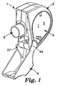
図1〜図3を参照すると、例示的デバイス(1)は再使用可能な本体部分(2)と、複数の容器(39)を収容する取り替え可能なカセット(5)とを備える。デバイスは、患者の口に挿入されるように適合した出口(3)を備える。或いは、出口は、患者の鼻腔に挿入されるように適合されてもよい(例えば、薬学的に有効な成分を鼻粘膜に送達するため)。以下、患者の口又は一方若しくは両方の鼻腔に挿入されるように適合した出口を、全般に、患者側出口の用語で称する。デバイスは、吸入器を使用していないとき、患者側出口(3)を被覆し、それによって埃や水分の侵入からデバイスを保護するために患者が使用できる蝶番式出口カバー(4)を具備してもよい。出口カバー(4)は、図1ではその開放位置で、図2および図3ではその閉鎖位置で示されている。例えば、出口カバー(4)に小さい点(pips)(図示せず)を、本体部分(2)に小さい圧痕(図示せず)を設け、これらが、患者が出口カバーを開放又は閉鎖するときに「クリック止め」相互作用をすることによって、デバイス又は出口が完全に開放している又は完全に閉鎖していることを表示する、患者のための触知可能なおよび/又は可聴のフィードバックをデバイスに提供してもよい。好適には、患者側出口(3)は、患者がそれを洗浄するために脱離され得るように、本体部分(2)に押込嵌めされる。 1-3, an exemplary device (1) comprises a reusable body portion (2) and a replaceable cassette (5) containing a plurality of containers (39). The device comprises an outlet (3) adapted to be inserted into the patient's mouth. Alternatively, the outlet may be adapted to be inserted into the patient's nasal cavity (eg, to deliver a pharmaceutically active ingredient to the nasal mucosa). Hereinafter, an outlet adapted to be inserted into a patient's mouth or one or both nasal cavities is generally referred to by the term patient-side outlet. The device comprises a hinged outlet cover (4) that can be used by the patient to cover the patient side outlet (3) and thereby protect the device from ingress of dust and moisture when the inhaler is not in use. May be. The outlet cover (4) is shown in its open position in FIG. 1 and in its closed position in FIGS. For example, the outlet cover (4) is provided with small pips (not shown) and the body part (2) is provided with a small indentation (not shown) when they open or close the outlet cover. Tactile and / or audible feedback for the patient indicating that the device or outlet is fully open or fully closed by “click-stop” interaction to the device May be provided. Preferably, the patient outlet (3) is a push fit on the body portion (2) so that the patient can be detached to clean it.
図2および図3は、例えば、新しいカセットと取り替えるため、例示的デバイス(1)の本体部分(2)から取り外された容器収容カセット(5)を示す。カセットの取り外しおよび取り替えは、典型的には単純な摺動を必要とし、カセットは、慣用的な「スナップ嵌め」特徴(図示せず)によって所定の位置に保持される。図3を参照すると、カセット(5)は、典型的には、取付穴(73)、カセット駆動開口部(53)およびカセット衝撃開口部(44)などの多数の開口部を具備する。カセット(5)を本体部分(4)に挿入するとき、カセットは、C形取付ポスト(10)、および、頭部(43)と中空のシャフト(54)(カム(55)を有する)とを有するインパクタ(13)などの本体部分内に配置されている構成要素(図2を参照)(これらの構成要素の機能を以下に説明する)をカセットの各開口部を通して受け入れることができる。カセットはまた、カセットが本体部分に挿入されるとき、患者側出口のスプレー入口(52)に面して患者側出口(3)の方に位置決めされる前開口部(51)(図3を参照)も具備する。図3では、容器を収容する回転式コンベア(50)が前開口部(51)を通して見えており、一方、別の容器(39)の底面がインパクタ開口部(44)を通して見えている。 2 and 3 show the container-housing cassette (5) removed from the body portion (2) of the exemplary device (1), for example to replace it with a new cassette. Removal and replacement of the cassette typically requires simple sliding, and the cassette is held in place by a conventional “snap fit” feature (not shown). Referring to FIG. 3, the cassette (5) typically comprises a number of openings such as mounting holes (73), cassette drive openings (53) and cassette impact openings (44). When inserting the cassette (5) into the body part (4), the cassette has a C-shaped mounting post (10) and a head (43) and a hollow shaft (54) (with a cam (55)). Components (see FIG. 2) disposed within the body portion, such as an impactor (13) having (see below the function of these components) can be received through each opening of the cassette. The cassette also has a front opening (51) positioned toward the patient outlet (3) facing the patient outlet spray inlet (52) when the cassette is inserted into the body portion (see FIG. 3). ). In FIG. 3, the rotary conveyor (50) containing the containers is visible through the front opening (51), while the bottom surface of another container (39) is visible through the impactor opening (44).
インパクタ(13)が、閉塞および可能な損傷を引き起こし得る位置(例えば、その発射位置)にないことを確実にするため、出口カバー(4)の輪郭(図1の4a)は、好適には、カバー(4)が閉鎖位置にある時だけ、従ってデバイスが静止位置(以下に、より詳細に説明する)にある時だけカセット(5)の取り外し又は取り替えができるように構成されている。また、インパクタ(13)がその発射位置にあるとき、インパクタの駆動シャフト(54)上のカム(55)が、カセット駆動開口部(53、図5を参照)を通過できない位置にあり、このようにして、カムは、インパクタがその発射位置にある時、カセット(5)を本体部分(2)内に保持することを容易にするのにも役立つ。 In order to ensure that the impactor (13) is not in a position that can cause occlusion and possible damage (eg its firing position), the contour of the outlet cover (4) (4a in FIG. 1) is preferably The cassette (5) can be removed or replaced only when the cover (4) is in the closed position and thus only when the device is in the rest position (described in more detail below). Also, when the impactor (13) is in its firing position, the cam (55) on the impactor drive shaft (54) is in a position where it cannot pass through the cassette drive opening (53, see FIG. 5). Thus, the cam also serves to facilitate holding the cassette (5) in the body portion (2) when the impactor is in its firing position.
例示的デバイス(1)のカセット(5)の組立分解図を示す図5を参照すると、カセットは外側(16)および内側(17)ケーシング半分を具備する。図5から分かるように、例示的デバイスは、それぞれが少なくとも穿孔可能な部分(39a)を備える12個の気密シール容器(39)を具備する。容器は細長いストリップ(19)上に設けられて、回転式コンベヤ(50)内に取り付けられ、それによって回転式コンベヤが2つのハウジング半分を(18、20)備えるようにしてもよい。 Referring to FIG. 5, which shows an exploded view of the cassette (5) of the exemplary device (1), the cassette comprises an outer (16) and an inner (17) casing half. As can be seen from FIG. 5, the exemplary device comprises twelve hermetic sealed containers (39), each comprising at least a pierceable portion (39a). The containers may be provided on an elongated strip (19) and mounted in a carousel (50) so that the carousel comprises two housing halves (18, 20).
各容器の穿孔可能な部分は、有利には箔の形態であってもよい(例えば、図5の構成要素39bを参照)。このような箔は、例えば、容器本体上に、(参照により本明細書に組み込まれる、本出願人らの同時係属中の出願であるGB0418738(2004年8月23日出願)に記載されるように)レーザー溶接されていてもよい(例えば、図5の構成要素39cを参照)。容器又はその構成要素のいずれか(例えば、箔又は容器本体)は、ステンレス鋼又はアルミニウムなどの金属で製造されていてもよい。容器の穿孔可能な部分は、撃針がその部分に接触する時、撃針の滑り又は撓みが最小限になるように、実質的に平面状の部分として設けられてもよい(後述)。容器の少なくとも穿孔可能な部分の厚さは、好適には厚くとも250μmである。容器の堅牢性のため、少なくとも穿孔可能な部分には少なくとも25μmの厚さが好都合である。高い堅牢性のため、少なくとも38μmの厚さが望ましく、より望ましくは少なくとも50μmである。例えば、穿刺による容器へのアクセスを更に容易にするため、厚くとも150μmの厚さが望ましく、より望ましくは厚くとも100μm、最も望ましくは厚くとも75μmである。図1〜図13に示されている例示的デバイスから分かるように、望ましいコンパクトなデバイスを提供するため、容器を、例えば、デバイス内の回転式コンベア上に、容器の少なくとも穿孔可能な部分が円の中心点から半径方向外側を向くようにして円形の全体形状に配置することが有利である。
The pierceable portion of each container may advantageously be in the form of a foil (see, for example,
各容器は、薬学的に有効な成分、および、HFA−134a、HFA−227又はこれらの混合物からなる液化エーロゾル噴射剤を含む加圧製剤の1回用量を収容する。本明細書に記載される吸入デバイスに使用される容器には、望ましくはエラストマーシールおよび隔膜および/又は分配弁がなく、これは、貯蔵中の漏れ、並びに外部環境からの空気又は水分の侵入、および/又は、シールおよび/又は隔膜材料との望ましくない相互作用を回避するのに有利である。容器は、望ましくは、HFA−134aおよび/又はHFA−227をベースにする医薬用製剤の1回用量を収容するのに適切な寸法に作られる(例えば、少量の又は最小限の量のヘッドスペースを有する)。このような薬学的に有効なエーロゾル製剤の1回用量を収容するため、容器の内容積は、望ましくは0.3ml未満、より望ましくは0.2ml以下、更により望ましくは0.15ml以下、最も望ましくは約0.15mlである。好適には、容器の内容積は、少なくとも0.1mlである。前述のように、加圧製剤の容積は、典型的には多くとも150μl、より望ましくは多くとも約100μl、最も望ましくは多くとも約80μlである。典型的には、加圧製剤の容積は、少なくとも約25μl、より望ましくは少なくとも約40μl、最も望ましくは少なくとも約50μlである。また、前述のように、容器内の内部圧力は、望ましくは、周囲温度のとき高くとも絶対圧力で7気圧、より望ましくは高くとも絶対圧力で約6.5気圧、更により望ましくは絶対圧力で約3〜約6.5気圧、最も望ましくは絶対圧力で約4〜約6.5気圧である。 Each container contains a single dose of a pharmaceutically active ingredient and a pressurized formulation comprising a liquefied aerosol propellant consisting of HFA-134a, HFA-227 or a mixture thereof. The containers used in the inhalation devices described herein desirably do not have elastomeric seals and diaphragms and / or dispensing valves, which may be leaks during storage, as well as air or moisture ingress from the outside environment, And / or to avoid undesirable interactions with the seal and / or diaphragm material. The container is desirably sized to accommodate a single dose of a pharmaceutical formulation based on HFA-134a and / or HFA-227 (eg, a small or minimal amount of headspace). Have). In order to accommodate a single dose of such pharmaceutically effective aerosol formulation, the internal volume of the container is desirably less than 0.3 ml, more desirably 0.2 ml or less, even more desirably 0.15 ml or less, most preferably Desirably about 0.15 ml. Suitably the internal volume of the container is at least 0.1 ml. As mentioned above, the volume of the pressurized formulation is typically at most 150 μl, more desirably at most about 100 μl, most desirably at most about 80 μl. Typically, the volume of the pressurized formulation is at least about 25 μl, more desirably at least about 40 μl, and most desirably at least about 50 μl. Also, as noted above, the internal pressure in the container is preferably at ambient temperature as high as 7 atm absolute pressure, more desirably at most about 6.5 atm absolute pressure, and even more desirably at absolute pressure. About 3 to about 6.5 atmospheres, most desirably about 4 to about 6.5 atmospheres in absolute pressure.
図1〜図13に示されている例示的実施形態に戻ると、各容器(39)は撃針(21)と連動している。このようにして例示的デバイスは、12の個々の撃針を備える。例示的実施形態から分かるように、各容器(39)の穿孔可能な部分(39a)がその関連する撃針(21)の方に、特に、穿孔可能な部分を穿孔できる、撃針の先端(21a)に設けられた穿刺器に面して位置決めされるように、撃針は、好適にはキャリヤに、例えば、回転式コンベア(50)に取り付けられてもよい。 Returning to the exemplary embodiment shown in FIGS. 1-13, each container (39) is associated with a firing pin (21). In this way, the exemplary device comprises 12 individual firing pins. As can be seen from the exemplary embodiment, the piercing tip (21a) of each container (39) can be pierced by its pierceable portion (39a), in particular towards its associated shooter (21). The firing pin may suitably be attached to the carrier, for example to the rotary conveyor (50), so that it is positioned facing the puncture device provided on the device.
各撃針は、望ましくは、チャネルを画成する内面を有し、ここで、チャネルは、少なくとも作動時に容器の方に位置決めされている第1の端部に1つの開口部を、少なくとも作動時に患者側出口の方に位置決めされている第2の端部に1つの開口部を有する。コンパクトなデバイスを提供するため、撃針のチャネルが実質的に単軸を画成し、出口通路がデバイスの作動時に実質的にその軸に沿って、又は、実質的にその軸に平行に延びることが望ましい。閉塞の可能性を更に最小限にするため、および/又は、好都合なエーロゾル特性を提供するため、チャネルは、有利には、第1の端部から第2の端部まで略円錐状であってもよい。 Each firing pin desirably has an inner surface that defines a channel, wherein the channel has at least one opening at a first end that is positioned toward the container upon actuation and at least the patient upon actuation. There is one opening at the second end that is positioned towards the side outlet. In order to provide a compact device, the firing channel defines a substantially single axis and the exit passage extends substantially along or substantially parallel to the axis when the device is activated. Is desirable. In order to further minimize the possibility of occlusion and / or to provide favorable aerosol properties, the channel is advantageously substantially conical from the first end to the second end. Also good.
撃針の最外部表面に、好適には、穿刺器、例えば、鋭利な先端部の形態の穿刺器が設けられている。望ましくは、少なくとも作動時に容器の方に位置決めされている撃針の先端の外面の形状は、円錐状である。撃針の先端(21a)の一部の拡大図を概略的に示す図26を参照すると、チャネル(60)の第1の端部(60a)は有利には撃針の最外部表面から僅かに後退し、前記穿刺器(21b)に隣接して位置決めされている。図27は、代替の先端(21a)の拡大図を示し、その中で、チャネル(60)を画成する内面は、膨張チャンバ(62)とスプレー微細化オリフィス(64)を提供するように構成されている。 A puncture device, for example in the form of a sharp tip, is preferably provided on the outermost surface of the firing pin. Desirably, the shape of the outer surface of the tip of the firing pin that is positioned toward the container at least in operation is conical. Referring to FIG. 26, which schematically shows an enlarged view of a portion of the tip (21a) of the firing pin, the first end (60a) of the channel (60) is advantageously slightly retracted from the outermost surface of the firing pin. , Positioned adjacent to the puncture device (21b). FIG. 27 shows an enlarged view of an alternative tip (21a) in which the inner surface defining the channel (60) is configured to provide an expansion chamber (62) and a spray micronization orifice (64). Has been.
撃針又はその先端は、好適には、容器の少なくとも穿孔可能な部分の穿孔を可能にする材料、例えば、金属又はポリマー材料を含む材料で製造される。驚くべきことに、前記部分が金属(例えば、ステンレス鋼又はアルミニウム)、例えば、金属箔(厚さ50μmのステンレス鋼箔など)から形成されているときでも、ポリブチレンテレフタレート、アセタール、および/又はポリカーボネートを含むものなどの射出成形されたポリマー撃針を使用して、気密シール容器の穿孔可能な部分を効果的に穿孔できることが分かった。傾斜切削されたステンレス鋼先端部などの代替の形態の穿刺器も好適である。 The firing pin or its tip is preferably made of a material that allows piercing of at least the pierceable portion of the container, such as a metal or polymeric material. Surprisingly, polybutylene terephthalate, acetal, and / or polycarbonate, even when the portion is formed from a metal (eg, stainless steel or aluminum), eg, a metal foil (such as a 50 μm thick stainless steel foil). It has been found that injection molded polymer shooters such as those containing can be used to effectively pierce the pierceable portion of the hermetically sealed container. Alternative forms of puncture devices such as slant cut stainless steel tips are also suitable.
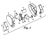
例示的実施形態および図5を再び参照すると、カセットはまた、歯車(22)、割出し(indexing)ヨーク(23)、割出しアーム(24)、および捩りばね(25)も備える。用量前進機構の一部を形成するこれらの構成要素の機能は、以下の説明で明らかになる。例示的実施形態の本体部分の構成要素の分解組立図を示す図4を参照すると、本体部分は、取り外し可能な患者側出口(3)、2つの構成要素(8、9)から形成される出口カバー(4)およびインパクタ(13)の他に、2つの外側ケーシング半分(6、7)からなるハウジング、ベーン(11)、ロッカー(12)、インパクタばね(14)、および駆動歯車(15)を具備する。インパクタ(13)とインパクタばね(14)は、ベーン(11)およびロッカー(12)と共に例示的デバイスの起動機構の一部を形成し、一方、駆動歯車(15)は用量前進機構の一部を形成する。これらの構成要素の機能を以下に説明する。 Referring again to the exemplary embodiment and FIG. 5, the cassette also includes a gear (22), an indexing yoke (23), an indexing arm (24), and a torsion spring (25). The function of these components forming part of the dose advancement mechanism will become apparent in the following description. Referring to FIG. 4, which shows an exploded view of the components of the body portion of the exemplary embodiment, the body portion is a removable patient-side outlet (3) and an outlet formed from two components (8, 9). In addition to the cover (4) and the impactor (13), a housing consisting of two outer casing halves (6, 7), a vane (11), a rocker (12), an impactor spring (14), and a drive gear (15) It has. The impactor (13) and impactor spring (14) together with the vane (11) and the rocker (12) form part of the activation mechanism of the exemplary device, while the drive gear (15) forms part of the dose advancement mechanism. Form. The function of these components will be described below.
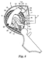
静止(および閉鎖)位置(図6)、準備位置(図7)、作動の中間位置(図8)および最終発射位置(図9)における、デバイスの内部の概略図を記載する図6〜図9を参照して例示的デバイスの作動又は起動を説明する。これらの図では、作動の様々な段階での容器と撃針の位置を見易いように、カセット(5)の内側ケーシング(17)並びに回転式コンベア(50)の内側ハウジング半分(20)を図から省略した。 FIGS. 6-9 describe schematic views of the interior of the device in the rest (and closed) position (FIG. 6), the ready position (FIG. 7), the intermediate position of operation (FIG. 8) and the final firing position (FIG. 9) The operation or activation of the exemplary device will be described with reference to FIG. In these figures, the inner casing (17) of the cassette (5) and the inner housing half (20) of the rotary conveyor (50) are omitted from the figure so that it is easy to see the position of the container and firing pin at various stages of operation. did.
図6から分かるように、静止および閉鎖位置では、出口カバーは閉鎖し、出口カバー(4)から延びるリセットアーム(27)はインパクタ(13)のアーム(28)に当接して静止し、それによってインパクタ(13)のアーム(28)の移動を防止する。インパクタ(13)の突起(29)は、ロッカー(12)の端部にある大フック(30)内に着座するが、突起(29)はフックと接触していない。 As can be seen from FIG. 6, in the rest and closed position, the outlet cover is closed and the reset arm (27) extending from the outlet cover (4) rests against the arm (28) of the impactor (13), thereby resting. The movement of the arm (28) of the impactor (13) is prevented. The protrusion (29) of the impactor (13) is seated in the large hook (30) at the end of the rocker (12), but the protrusion (29) is not in contact with the hook.
患者が、(図7に示すように)カバー(4)を開放するとき、リセットアーム(27)はインパクタ(13)のアーム(28)から引き離される。インパクタ(13)は、それによってインパクタばね(14:明確に分かるように図7〜図9から省略されているが、図6から認識できる)の影響で、インパクタ突起(29)がロッカー(12)の大フック(30)に当接して静止するまで、僅かに前方に(図7では左から右に、即ち、時計回りに)移動する。デバイスのこの準備位置では、ベーン(11)、ロッカー(12)、インパクタ(13)およびインパクタばね(14)を備えるデバイスの起動機構は、ロッカー(12)の転心(38)を中心としてインパクタばね(14)の力が僅かに「中心を越える(over centre)」方向に作用するため、安定である。しかし、ベーン(11)およびロッカー(12)の好ましい幾何学的形態によって提供される「機械的利点」のため、患者側出口(3)を通して吸入することによって起動機構を容易に解放することができる。 When the patient opens the cover (4) (as shown in FIG. 7), the reset arm (27) is pulled away from the arm (28) of the impactor (13). The impactor (13) is thereby affected by the impactor spring (14: omitted from FIGS. 7 to 9 as can be clearly seen, but can be recognized from FIG. 6). It moves slightly forward (from left to right in FIG. 7, ie, clockwise) until it comes into contact with the large hook (30) and stops. In this preparation position of the device, the activation mechanism of the device comprising the vane (11), the rocker (12), the impactor (13) and the impactor spring (14) is the impactor spring centered on the rolling center (38) of the rocker (12). Since the force of (14) acts slightly in the “over center” direction, it is stable. However, because of the “mechanical advantage” provided by the preferred geometry of the vane (11) and the rocker (12), the activation mechanism can be easily released by inhaling through the patient outlet (3). .
図8を参照すると、患者が患者側出口(3)を口に入れ、吸入するとき、空気は、空気入口(31)から引き込まれ、内部空気流チャネル(32)を通り、ベーン(11)を経て内部空気流開口部(33)を通り、空気入口(34)を通って患者側出口(3)に入る。このため、ベーン(11)がその回転軸(35)を中心に回転する時、ベーン(11)は(図8では反時計回りに)上り始める。全部の側の締り嵌め式の壁(図8を参照すると、例えば、本体部分(2)の外側ケーシング半分(6、7(6は見えていない))、カセット(5)の外側ケーシング半分(16、17(17は見えていない))、および本体部分内に設けられた壁(2aおよび2b))は、この段階で空気流がベーン(11)をあまり迂回しないことを確実にする。ベーン(11)が回転軸(35)を中心に回転する時、ベーン(11)の歯車の歯(11a)によってロッカー(12)の歯車の歯(37)が移動し、そのためロッカー(12)がそれ自体の回転軸(38)を中心に時計回りに回転する。ロッカーが回転する時、その大フック(30)はインパクタ(13)上の突起(29)から摺動して離れ始める。 Referring to FIG. 8, when the patient enters the patient side outlet (3) into the mouth and inhales, air is drawn from the air inlet (31), passes through the internal air flow channel (32), and passes through the vane (11). Through the internal air flow opening (33), through the air inlet (34) and into the patient outlet (3). For this reason, when the vane (11) rotates about its rotation axis (35), the vane (11) starts to rise (counterclockwise in FIG. 8). Close-fitting walls on all sides (see FIG. 8, for example, the outer casing half (6, 7 (6 is not visible)) of the body part (2), the outer casing half (16 of the cassette (5)) , 17 (17 is not visible)) and the walls (2a and 2b) provided in the body part ensure that the air flow does not divert too much around the vane (11) at this stage. When the vane (11) rotates about the rotation axis (35), the gear teeth (11a) of the vane (11) move the gear teeth (37) of the rocker (12), so that the rocker (12) It rotates clockwise about its own axis of rotation (38). As the rocker rotates, its large hook (30) begins to slide away from the protrusion (29) on the impactor (13).
患者が吸入し続ける時、(図9に示すように)ベーン(11)は更に(反時計回りに)回転し続け、次にロッカー(12)は大フック(30)がインパクタ(13)の突起(29)を解放するのに十分回転する。インパクタ(13)はインパクタばね(14)によって駆動され、インパクタ(13)が患者側出口(3)と整列した容器(39−1)を打つように高速で自由に(図9では時計回りに)回転する。特に、インパクタ(13)の頭部(43:図9では明瞭に見えていない)が容器(39−1)の基部を打つ時、容器はその関連する撃針の方に移動し(押され)、穿孔可能な部分を備える容器の上面がその関連する撃針(21a)に打ち当たり、その結果、後者が穿孔可能な部分に穴を開ける。容器に穴が開けられる時、撃針の外面(その先端)は蓋と一時的なシールを作り、その間、容器(39−1)内の医薬製剤の用量が撃針(21−1)のチャネルを通過し、入口(52)および患者側出口(3)の通路を通り出て患者に到達する。噴出するエーロゾルの周囲に環状の空気ジャケットを作り出すため、患者側出口は、空気入口(34)が設けられた内側スペーサ部分(40)(入口(図1の52)と患者側出口の略円筒状の外側部分(3a)の間)を具備してもよい。患者側入口の内側スペーサ部分(40)の内面は、望ましくは略円筒状である。デバイスの発射位置でインパクタ(13)のアーム(28)が特徴的位置にあるため、好適にはアーム(有利には明るい色に着色されていてもよい)をデバイスのウインドウ(図4の26)に現れる表示器として使用し、それによって、機構が起動されたこと(即ち、用量が放出されたこと)を患者に表示してもよい。 When the patient continues to inhale, the vane (11) continues to rotate further (counterclockwise) (as shown in FIG. 9), and then the rocker (12) has a large hook (30) protruding from the impactor (13). Rotate enough to release (29). The impactor (13) is driven by an impactor spring (14) and is freely at high speed (clockwise in FIG. 9) so that the impactor (13) strikes the container (39-1) aligned with the patient outlet (3). Rotate. In particular, when the head of the impactor (13) (43: not clearly visible in FIG. 9) strikes the base of the container (39-1), the container moves (pressed) towards its associated firing pin, The upper surface of the container with the pierceable part strikes its associated firing pin (21a), so that the latter punctures the pierceable part. When the container is punctured, the outer surface of the firing needle (its tip) creates a temporary seal with the lid, during which time the dosage of the pharmaceutical formulation in the container (39-1) passes through the channel of the firing needle (21-1) The patient passes through the passageway of the inlet (52) and the patient side outlet (3) to reach the patient. In order to create an annular air jacket around the jetting aerosol, the patient outlet is an inner spacer portion (40) provided with an air inlet (34) (the inlet (52 in FIG. 1)) and the substantially cylindrical shape of the patient outlet. Between the outer portions (3a). The inner surface of the inner spacer portion (40) of the patient side entrance is desirably substantially cylindrical. Since the arm (28) of the impactor (13) is in a characteristic position at the launch position of the device, preferably the arm (which may be advantageously colored brightly) is placed in the device window (26 in FIG. 4). May be used as an indicator that appears to indicate to the patient that the mechanism has been activated (ie, that a dose has been released).
発射位置における(即ち、図9の通り)反対側からの例示的デバイスの概略内部図を示す図10を参照すると、インパクタ(13)の前縁(41)は、カセットが当接して静止する内部前壁(42)の輪郭に合致する好適な形状であってもよい。これらの合致する輪郭のため、カセットが存在しないときに吸入器が起動されても、運動するインパクタ(13)のエネルギーは広い領域にわたって安全に消散される。しかし、患者側出口(3)の内側スペーサ部分(40)に空気入口(34)が存在するため、カセットがないことによって作り出される内側スペーサ部分を通る空気の漏れは実際、カセットが存在しない時、呼吸によって起動機構を解放できないような程度にベーン(11)を迂回する。しかし、準備されているが空の(即ち、カセットが装填されていない)デバイスを極端に荒く取り扱うと、起動機構が解放される可能性がある。 Referring to FIG. 10, which shows a schematic internal view of an exemplary device from the opposite side in the firing position (ie as in FIG. 9), the leading edge (41) of the impactor (13) is the interior where the cassette rests against. It may be a suitable shape that matches the contour of the front wall (42). Due to these matching contours, the energy of the moving impactor (13) is safely dissipated over a large area even if the inhaler is activated when no cassette is present. However, since there is an air inlet (34) in the inner spacer portion (40) of the patient outlet (3), air leakage through the inner spacer portion created by the absence of the cassette is actually when no cassette is present, Bypass the vane (11) to such an extent that the activation mechanism cannot be released by breathing. However, handling a prepared but empty device (i.e., no cassette loaded) in an extremely rough manner can release the activation mechanism.
デバイスの内部の概略図を記載する図11および図12を参照して、例示的デバイスの起動機構のリセットを説明するが、図11では出口カバーは部分的に閉鎖されており、図12では出口カバーはほとんど完全に閉鎖されている。明確に分かるように、インパクタばね(14)を省略した。図11および図12では(図6〜図9とは異なり)、カセット(5)の内側ケーシング半分(17)を省略しなかったため、容器と撃針は見えていない。患者が出口カバー(4)を閉鎖する時、カバーのリセットアーム(27)はインパクタ(13)のアーム(28)の方に移動し(図11)、次いでインパクタ(13)をそのばね(14:これも図11および図12から省略されている)の力に抗して押し戻す(図11および図12)。インパクタ(13)が(図6に示すように)その静止位置の方に戻る時、その突起(29)はロッカー(12)を当接支持し、それをその回転軸(38)を中心として僅かに反時計回りに回転させる。それが回転する時、ロッカーは、歯車の歯(37)とベーンの歯との相互作用により、ベーン(11)を引いて再び閉鎖させる(図12)。リセットアーム(27)の上面は、リセットプロセスの最終部分の間(図12に示されている位置から図6に示されている位置まで)、リセットアーム(27)とインパクタ(13)の相互作用によって力が「中心を越えて作用する(go over centre)」ように、好適な輪郭に形成されてもよい。換言すれば、インパクタばね(14)の力は、(図6に示されているように)インパクタ(13)と出口カバー(4)を僅かにそれぞれの「静止」位置の方に付勢する傾向がある。最後に、インパクタ(13)はロッカー(12)から僅かに離れ、このようにしてデバイスの静止位置でロッカー(12)とベーン(11)の機構から「負荷を取り除く」。 11 and 12, which describe schematic views of the interior of the device, will be described with reference to resetting the activation mechanism of the exemplary device, in which the outlet cover is partially closed and in FIG. The cover is almost completely closed. For clarity, the impactor spring (14) was omitted. 11 and 12 (unlike FIGS. 6 to 9), the inner casing half (17) of the cassette (5) was not omitted, so the container and firing pin are not visible. When the patient closes the outlet cover (4), the reset arm (27) of the cover moves toward the arm (28) of the impactor (13) (FIG. 11), and then the impactor (13) is moved to its spring (14: This is pushed back against the force (which is also omitted from FIGS. 11 and 12) (FIGS. 11 and 12). When the impactor (13) returns to its rest position (as shown in FIG. 6), its protrusion (29) bears against and supports the rocker (12), which is slightly centered about its rotational axis (38). Rotate counterclockwise to. As it rotates, the rocker pulls the vane (11) and closes again (FIG. 12) due to the interaction of the gear teeth (37) with the vane teeth. The upper surface of the reset arm (27) interacts with the reset arm (27) and the impactor (13) during the final part of the reset process (from the position shown in FIG. 12 to the position shown in FIG. 6). May be formed into a suitable profile such that the force “go over center”. In other words, the force of the impactor spring (14) tends to urge the impactor (13) and outlet cover (4) slightly towards their "rest" positions (as shown in FIG. 6). There is. Finally, the impactor (13) is slightly separated from the rocker (12), thus "unloading" the locker (12) and vane (11) mechanism in the rest position of the device.
まだ説明していないが、図1〜図13に示されている例示的実施形態では、出口カバー(4)の開閉時に、割出しヨーク(23)、割出しアーム(24)、捩りばね(25)、歯車(22)および駆動歯車(15)を具備する用量前進機構が、回転式コンベア(50)、および、従って発射される容器とその関連する撃針を適切に移動させることが分かる。第2の例示的実施形態は類似の用量前進機構を組み込むため、図14〜図25に示されている第2の例示的実施形態を参照して前記機構とその動作を説明する。 Although not yet described, in the exemplary embodiment shown in FIGS. 1-13, when the outlet cover (4) is opened and closed, the indexing yoke (23), the indexing arm (24), the torsion spring (25 ), A dose advancement mechanism comprising a gear (22) and a drive gear (15) is seen to properly move the rotary conveyor (50) and thus the containers to be fired and their associated firing needles. Since the second exemplary embodiment incorporates a similar dose advancement mechanism, the mechanism and its operation will be described with reference to the second exemplary embodiment shown in FIGS.
図13は、第1の例示的実施形態の他の特徴を示す。患者が吸入器本体部分(2)からカセット(5)を取り外すことができるため、およびその時歯車(22)が露出されるため、患者が回転式コンベヤを用量と用量の間に、即ち、容器(39)が患者側出口(3)との位置合わせから外れる位置に(特に入口(52)を患者側出口に)移動させないことを確実にするため、改ざん防止手段が設けられている。これらの改ざん防止手段は、カセット(5)が本体部分(2)の外にあるとき、割出しヨーク(23)の移動を防止する小さいクリップ(図示せず)の形態を取る。クリップは、カセットの外側ケース(16)の壁から片持ち梁のように飛び出ている一体ばね取付台(71)に取り付けられている。高ポスト(図5の70)もばね取付台(71)に取り付けられている。カセット(5)を本体部分(2)に押し込む時、本体部分(2)の別のC形の輪郭のポスト(図2の10)はアクセス穴(図3の73)を通ってカセット(5)に入り、高ポスト(70)と端部同士で接する。このため、高ポスト(70)を支持するばね取付台(71)は僅かに撓み、クリップ(図示せず)を割出しヨーク(23)から離れるように撓ませ、それによって、カセットが本体部分(2)の中に取り付けられるとき、(前進中、必要に応じて)ヨークの回転が可能になるが、カセットが本体部分(2)の外側にある(即ち、その中に取り付けられない)ときはこのようにならない。 FIG. 13 illustrates other features of the first exemplary embodiment. Because the patient can remove the cassette (5) from the inhaler body part (2) and then the gear (22) is exposed, the patient can move the rotary conveyor between doses, i.e. containers ( In order to ensure that 39) does not move out of alignment with the patient-side outlet (3) (especially the inlet (52) to the patient-side outlet), tamper-proof means are provided. These tamper prevention means take the form of small clips (not shown) that prevent the indexing yoke (23) from moving when the cassette (5) is outside the body portion (2). The clip is attached to an integral spring mounting base (71) protruding like a cantilever from the wall of the outer case (16) of the cassette. A high post (70 in FIG. 5) is also attached to the spring mount (71). When the cassette (5) is pushed into the main body part (2), another C-shaped profile post (10 in FIG. 2) of the main body part (2) passes through the access hole (73 in FIG. 3) through the cassette (5). And contacts the high post (70) at the ends. For this reason, the spring mount (71) that supports the high post (70) is slightly deflected, and the clip (not shown) is deflected away from the indexing yoke (23), so that the cassette is 2) When mounted in (when advancing, if necessary) the yoke can be rotated, but when the cassette is outside the body part (2) (ie not mounted in it) Not like this.
第1の例示的実施形態は、また、回転式コンベア(50)を調心する構成要素を具備する。特に、図13を参照すると、内側ケーシング(17)に、回転式コンベアの上面にある、各容器に対して1つの、一連の凹部又は窪み(45)(図5を参照)と相互作用する一体弾性フィンガー(72)が設けられている。用量前進時に弾性フィンガーと個々に協働するこれらの凹部(45)は、必要な程度の自動調心アラインメント又は回転式コンベアのパーキング位置の量子化を提供する。フィンガーと凹部の構成からの触知可能なおよび/又は可聴のフィードバックは、望ましくは、次の用量が成功裏に前進されたという表示を患者に提供し得る。 The first exemplary embodiment also comprises components that align the carousel (50). In particular, referring to FIG. 13, the inner casing (17) interacts with a series of recesses or depressions (45) (see FIG. 5), one for each container, on the top of the carousel. Elastic fingers (72) are provided. These recesses (45), which cooperate individually with the elastic fingers during dose advancement, provide the required degree of self-aligning alignment or quantization of the parking position of the carousel. Tactile and / or audible feedback from the finger and recess configuration may desirably provide an indication to the patient that the next dose has been successfully advanced.
図14〜図25は、本発明による第2の例示的実施形態を示す。この例示的実施形態は、再充填不可能な呼吸作動デバイスである。この例示的デバイスは図1〜図13に示されているデバイスに類似しており、主な違いは、デバイスが再充填不可能であり、従ってデバイスが、完全に密閉されている本体(2)を具備することである。 FIGS. 14-25 illustrate a second exemplary embodiment according to the present invention. This exemplary embodiment is a non-refillable respiratory actuation device. This exemplary device is similar to the device shown in FIGS. 1-13, the main difference being that the device is non-refillable and thus the device is fully sealed (2) It is to comprise.
図14を参照すると、デバイス(1)は、本体(2)、マウスピースの形態の患者側出口(3)、および、リセットアーム(27)が設けられた蝶番式の出口カバー(4)を備える。この実施形態では、出口と、中に容器および撃針が取り付けられている回転式コンベア(50、図14では見えていない)との良好な接触を容易にするため、明確な停止位置を有するねじ込み継手が患者側出口(3)に設けられている。例えば、患者の指が入ることを防止するため、前部空気入口(31)の幅のほとんどにわたって格子(65)が設けられてもよい。図14〜図25のどれにも示されていないが、この第2の例示的実施形態は、第1の例示的実施形態のように、呼吸作動によって作動され、第1の例示的実施形態について前述されたのと同様に構成され、操作される起動機構(インパクタ(13)(カム(55)が設けられた中空のインパクタシャフト(54)を有する)、インパクタばね(14)、ベーン(11)、およびロッカー(12)を備える)を具備する。第1の例示的実施形態の起動に関する完全な説明が第2の実施形態に当てはまることが分かる。 Referring to FIG. 14, the device (1) comprises a body (2), a patient outlet (3) in the form of a mouthpiece, and a hinged outlet cover (4) provided with a reset arm (27). . In this embodiment, a threaded joint with a well-defined stop position to facilitate good contact between the outlet and a rotary conveyor (50, not visible in FIG. 14) in which the containers and firing pins are mounted. Is provided at the patient side outlet (3). For example, a grid (65) may be provided over most of the width of the front air inlet (31) to prevent entry of the patient's fingers. Although not shown in any of FIGS. 14-25, this second exemplary embodiment, like the first exemplary embodiment, is actuated by breathing actuation, with respect to the first exemplary embodiment. An activation mechanism (impactor (13) (having a hollow impactor shaft (54) provided with a cam (55)), impactor spring (14), and vane (11) configured and operated in the same manner as described above. And a locker (12). It can be seen that the complete description for activation of the first exemplary embodiment applies to the second embodiment.
デバイスの一部の斜視図を記載する図15を参照すると、例示的デバイスの容器と撃針を収容する回転式コンベア(50)は保持クリップ(63)によって本体(2)の半分の1つの中に保持されている。回転式コンベア(50)上の小さい凹部(例えば、46)と協働する、突出するV形の点がクリップ(63)の下側に成形されているが、図15では見えず、1つの凹部が各容器(39)と関連し、各用量の前進後、回転式コンベア(50)、および従って各容器(39)の位置の調心が更に確実に行われる。また、点と凹部の構成からの触知可能なおよび/又は可聴のフィードバックは、望ましくは、次の容器が成功裏に前進され、従って作動される位置にあるという信号を患者に提供する。 Referring to FIG. 15, which describes a perspective view of a portion of the device, the carousel (50) containing the container and firing pin of the exemplary device is placed in one of the halves of the body (2) by a retaining clip (63). Is retained. A protruding V-shaped point, which cooperates with a small recess (eg 46) on the carousel (50), is molded under the clip (63), but is not visible in FIG. Is associated with each container (39), and after each dose advancement, alignment of the rotary conveyor (50), and thus the position of each container (39), is more reliably performed. Also, tactile and / or audible feedback from the point and recess configuration desirably provides the patient with a signal that the next container is in a position that has been successfully advanced and thus actuated.
用量前進の様々な段階におけるデバイスの内部の一部の概略図(図16〜図24)および用量前進機構のサブアセンブリの分解組立図(図25)を記載する図16〜図25を参照して例示的デバイスの用量前進又は割出し(indexing)を説明する。明確に分かるように、容器、撃針、および回転式コンベア構造のほとんど、並びに起動機構の一部を形成する構成要素のほとんどを図16〜図24では省略した。 Referring to FIGS. 16-25, which depict schematic views (FIGS. 16-24) of portions of the interior of the device at various stages of dose advancement and exploded views (FIG. 25) of the subassembly of the dose advancement mechanism (FIG. 25). Illustrates dose advancement or indexing of an exemplary device. As can be clearly seen, most of the container, firing pin, and rotary conveyor structure, as well as most of the components that form part of the activation mechanism, have been omitted in FIGS.
有利には、例示的デバイスの用量前進機構は、患者側出口カバーが開放されるとき、特に前の容器が衝撃を受けた、従って発射されたという条件で、回転式コンベアを前進させ、次に発射される容器を位置合わせの位置まで移動させ(即ち、患者側出口(およびその入口)と整列させ)、このようにして作動の準備を整える。 Advantageously, the dose advancement mechanism of the exemplary device advances the carousel when the patient exit cover is opened, especially on the condition that the previous container was impacted and thus fired, and then The fired container is moved to the alignment position (ie aligned with the patient outlet (and its inlet)) and thus ready for operation.
図16は、出口カバー(4)が閉鎖している、例示的デバイス(1)の静止位置における内部図を示す。容器と撃針を収容する回転式コンベア(50)がデバイスの中心ボス(66)上に留められ、保持クリップ(63)で所定の位置に保持されている。割出しヨーク(23)も中心ボス(66)上に取り付けられているが、回転式コンベア(50)に対して自由に回転し、その歯は歯車(22)の歯と係合する。割出しアーム(24)は、割出しヨーク(23)上に成形されているペグ(49)上に留められて着座する。割出しアーム(24)が外向きに付勢され、(即ち、図16のペグ(49)を中心として時計回りに回転し)、その割出し歯(57)が回転式コンベア(50)の縁の内側にある一連の回転式コンベア前進凹部(56)の1つに係合するように、捩りばね(25)は、割出しアーム(24)と割出しヨーク(23)上のばね止め(59)との間に保持される。このような凹部の1つ(例えば、56)は、回転式コンベア(50)の12個の用量収容容器のそれぞれに対応する。割出し歯(57)の形状と回転式コンベア前進凹部(56)の形状、およびそれらの相対的位置と角度は、捩りばね(25)がそれらをどちらかの回転方向で係合するように付勢された状態に保つ傾向を有するようになっている。湾曲した付勢連結具(67)は本体(2)の内面上の点(67a)、および割出しヨーク(23)上に設けられた延長部(23a)上の点(67b)に固定されてもよい。固定点(67a、67b)は、付勢連結具(67)の端部の幾らかの回転運動を可能にするが、付勢連結具が緩くないように離間されている。歯車(22)にはシャフト(22a)が設けられている。シャフト(22a)は、インパクタ(13、完全には示されていない)のカム(55)を有する中空のインパクタシャフト(54)に挿入されている。カム(55)は、ある一定の状況(以下に詳述する)では、割出しアーム(24)上に設けられた爪(36)と相互作用する。前述のように、歯車(22)の歯は、割出しヨーク(23)の歯と係合する。歯車(22)の歯は、また、駆動歯車(15)の歯とも係合する。次に駆動歯車は、出口カバー(4)の内面に設けられた正方形のペグ(58、見えていない(第1の例示的実施形態の正方形のペグを示す図4を参照))と係合する。 FIG. 16 shows an internal view in the rest position of the exemplary device (1) with the outlet cover (4) closed. A rotary conveyor (50) containing the container and firing pin is fastened on the central boss (66) of the device and held in place by a retaining clip (63). An indexing yoke (23) is also mounted on the central boss (66) but rotates freely with respect to the rotary conveyor (50) and its teeth engage with the teeth of the gear (22). The index arm (24) is seated on the peg (49) formed on the index yoke (23). The indexing arm (24) is urged outward (ie, rotates clockwise about the peg (49) in FIG. 16) and its indexing teeth (57) are the edges of the rotary conveyor (50) The torsion spring (25) is spring-loaded (59 on the indexing arm (24) and indexing yoke (23) so as to engage one of a series of rotary conveyor advancement recesses (56) inside the ) Is held between. One such recess (eg 56) corresponds to each of the twelve dose containers of the carousel (50). The shape of the index teeth (57) and the rotary conveyor advancement recess (56), and their relative position and angle are applied so that the torsion spring (25) engages them in either direction of rotation. It has a tendency to stay in a state of being struck. The curved biasing connector (67) is fixed to a point (67a) on the inner surface of the main body (2) and a point (67b) on the extension (23a) provided on the indexing yoke (23). Also good. The securing points (67a, 67b) allow some rotational movement of the end of the biasing coupler (67) but are spaced apart so that the biasing coupler is not loose. The gear (22) is provided with a shaft (22a). The shaft (22a) is inserted into a hollow impactor shaft (54) having a cam (55) of the impactor (13, not fully shown). The cam (55) interacts with the pawl (36) provided on the indexing arm (24) in certain situations (detailed below). As described above, the teeth of the gear (22) engage with the teeth of the indexing yoke (23). The teeth of the gear (22) also engage with the teeth of the drive gear (15). The drive gear then engages a square peg (58, not visible (see FIG. 4 showing the square peg of the first exemplary embodiment)) provided on the inner surface of the outlet cover (4). .
図17〜図19は、出口カバー(4)が部分的に(約65°で)開放されている時、ほとんど完全に(約120°で)開放している時、および完全に(約130°で)開放している時の、デバイスの内部の概略図を記載する。 17-19 show that when the outlet cover (4) is partially opened (at about 65 °), almost completely open (at about 120 °), and completely (about 130 °). Include a schematic diagram of the interior of the device when it is open.
図17を参照すると、出口カバー(4)が開放される時、その正方形のペグ(58、見えていない)は、駆動歯車(15)の対応する正方形のキー溝(15a、見えていない)を移動させ、両方の歯車(15、22)を回転させる。次に歯車(22)が割出しヨーク(23)を回転させる。それがこのようにする時、湾曲した付勢連結具(67)の2つの固定点間の距離は僅かに減少し、そのため付勢連結具(67)が曲がり、それによって出口カバーを開放する際に幾らかの抵抗が提供される。付勢連結具(67)の成形時の湾曲は、その両端が互いに近づく時、それが座屈する傾向がなく曲がることを確実にする。割出しヨーク(23)と割出しアーム(24)が回転する時、割出し歯(57)は回転式コンベア(50)を引いて回動させる。 Referring to FIG. 17, when the outlet cover (4) is opened, its square peg (58, not visible) will have a corresponding square keyway (15a, not visible) of the drive gear (15). Move and rotate both gears (15, 22). The gear (22) then rotates the indexing yoke (23). When it does this, the distance between the two fixed points of the curved biasing connection (67) is slightly reduced, so that the biasing connection (67) bends and thereby opens the outlet cover. Some resistance is provided. The bending of the biased connector (67) during molding ensures that when its ends approach each other, it does not tend to buckle and bends. When the indexing yoke (23) and the indexing arm (24) rotate, the indexing tooth (57) pulls and rotates the rotary conveyor (50).
図18を参照すると、出口カバー(4)を開放し続ける時、歯車(15、22)と割出しヨーク(23)が更に回転することにより、割出しアーム(24)上の割出し歯(57)は、ほぼ次の容器(図示せず)が患者側出口(3)と整列する位置まで、回転式コンベア(50)を引いて回動させる。その間、付勢連結具(67)はその元の湾曲に戻り、このようにして、出口カバーの開放を補助する幾らかの追加の力を提供する。付勢連結具(67)は出口カバー(4)をその完全に開放した位置又は完全に閉鎖した位置のどちらかに付勢する役割をするため、付勢連結具(67)は、このようにして有利な「確実な開放−確実な閉鎖」の特徴を提供し、それによって容器の完全な前進、および、それらとインパクタおよび患者側出口との正しい位置合わせを確実にすることに役立つ。この構成は、また、出口カバー(4)が正しく開放又は閉鎖されたという触知可能なフィードバックを患者に提供する。それはまた、完全に開放されたとき、出口カバー(4)がぐらぐら揺れ動くことを防止する。 Referring to FIG. 18, as the outlet cover (4) continues to be opened, the gears (15, 22) and the indexing yoke (23) further rotate, thereby causing the indexing teeth (57 on the indexing arm (24) to rotate. ) Pulls and rotates the rotary conveyor (50) until the next container (not shown) is aligned with the patient outlet (3). Meanwhile, biasing connector (67) returns to its original curvature, thus providing some additional force to assist in opening the outlet cover. Since the biasing connector (67) serves to bias the outlet cover (4) to either its fully open or fully closed position, the biasing connector (67) is thus Provide an advantageous “reliable open-reliable close” feature, thereby ensuring complete advancement of the containers and correct alignment of them with the impactor and patient outlet. This configuration also provides the patient with tactile feedback that the outlet cover (4) has been correctly opened or closed. It also prevents the outlet cover (4) from wobbling when fully opened.
図19を参照すると、出口カバーがその完全に開放された位置に開放する時、割出しヨーク(23)が更に回転することにより、割出しアーム(24)の鼻が本体の内面上に成形された止めペグ(68)と衝突し、それによって割出しアーム(24)が(図19に示すように)反時計回りに、捩りばね(25、図19には示されていない)の力に抗して回転する。割出しアーム(24)の回転により、割出し歯(57)は、それが移動させてきた回転式コンベア前進凹部(56−1)から係脱する。回転式コンベア(50)は、この時、吸入の準備が整った位置にあり、デバイスは患者による呼吸作動の準備が整っている。この構成によって、発射される容器は吸入開始前に穿孔の準備が整った状態に位置決めされ、それによって、容器前進が起動機構を遅れさせず、起動機構からのエネルギーを要しないことが確実になる。 Referring to FIG. 19, when the outlet cover is opened to its fully open position, the index yoke (23) is further rotated to form the nose of the index arm (24) on the inner surface of the body. The indexing arm (24) counter-clockwise (as shown in FIG. 19) and resists the force of the torsion spring (25, not shown in FIG. 19). Then rotate. The rotation of the index arm (24) causes the index tooth (57) to disengage from the rotary conveyor advance recess (56-1) that it has moved. The carousel (50) is now in a position ready for inhalation and the device is ready for breathing operation by the patient. This arrangement positions the fired container in a state ready for drilling before inhalation begins, thereby ensuring that container advance does not delay the activation mechanism and does not require energy from the activation mechanism. .
患者はこの時点で、デバイスを使用しないことを決定し、出口カバーを閉鎖してもよい。この場合、本明細書に記載されるデバイスは、有利には、前の容器が発射されるまで、次に発射される容器が前進しない前進機構を提供する。特に、前進機構は、出口カバーの開放時に前進した容器が作動されなかった(発射されなかった)場合、出口カバーの閉鎖時に前記容器が元の前進する前の位置に戻るように構成され、出口カバーに連結されている。 At this point, the patient may decide not to use the device and close the outlet cover. In this case, the devices described herein advantageously provide an advancement mechanism in which the next fired container does not advance until the previous container is fired. In particular, the advancement mechanism is configured to return the container to its original pre-advance position when the outlet cover is closed if the advanced container is not actuated (fired) when the outlet cover is opened. Connected to the cover.
特に、図20は、デバイスが使用されなかった(即ち、デバイスの呼吸作動がなく、従って容器が作動されなかった)が、患者が出口カバーを再閉鎖し始めた場合の、デバイスの内部を概略的に示す。(図20では、出口カバー(4)は約125°の位置まで閉鎖されている。)患者が出口カバー(4)を閉鎖し始める時、これによって歯車(15、22)の逆回転が起こる。次にこの反対回転によって割出しヨーク(23)の逆回転が起こり、それによって割出しアーム(24)が止めペグ(68)から離れることが可能になり、このようにして割出し歯(57)が、前に駆動させた同じ回転式コンベア前進凹部(56−1)と再係合し始めることが可能になる。次いで、出口カバー(4)を更に閉鎖すると、カバーの開放中に起こった事象の順番が逆転し、回転式コンベア(50)はこのようにしてその元の位置に戻る。付勢連結具(67)は、出口カバー(4)がその完全に閉鎖した位置に戻るのを確実にすることに役立つ。患者がデバイスを実際に使用することなく(即ち、カバーの開放中、前進した容器を作動させることなく)単に出口カバーを開閉するとき、前進の逆転を可能にする前進機構が設けられていると、容器が浪費されないことが確実になる。容器が高価な薬学的に活性な成分を収容するとき、これは特に重要である。 In particular, FIG. 20 schematically illustrates the interior of the device when the device was not used (ie, the device was not breathing and therefore the container was not activated), but the patient began to reclose the outlet cover. Indicate. (In FIG. 20, the outlet cover (4) is closed to a position of about 125 °.) When the patient begins to close the outlet cover (4), this causes a reverse rotation of the gears (15, 22). This counter rotation then causes a reverse rotation of the indexing yoke (23), thereby allowing the indexing arm (24) to move away from the stop peg (68), thus indexing teeth (57). Can begin to re-engage with the same rotary conveyor advancement recess (56-1) that was previously driven. If the outlet cover (4) is then further closed, the sequence of events that occurred during the opening of the cover is reversed and the carousel (50) is thus returned to its original position. The biasing connector (67) helps to ensure that the outlet cover (4) returns to its fully closed position. When an advancement mechanism is provided that allows reversal of advancement when the patient simply opens and closes the outlet cover without actually using the device (ie, without opening the advanced container while the cover is open) , Ensuring that the container is not wasted. This is particularly important when the container contains expensive pharmaceutically active ingredients.
患者がデバイスを使用した(例えば、呼吸作動によってデバイスを作動させ、このようにして前進した容器を発射させた)場合、前進機構は、出口カバーの閉鎖時に消費された容器が位置合わせの位置に留まり、次いで、出口カバーを逐次的に開放する時、次に発射される容器が位置合わせ位置に前進するように構成されている。 If the patient has used the device (eg, actuating the device by breathing and firing the thus advanced container), the advancement mechanism will ensure that the container consumed when the outlet cover is closed is in the aligned position. When it stays and then sequentially opens the outlet cover, the next fired container is configured to advance to the alignment position.
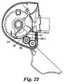
例示的実施形態を参照すると、これは、作動(容器の発射)前後の内部図を示す図19および図21と、デバイスの作動後に出口カバーを閉鎖する時の図を示す図22〜図24を比較することによって最もよく分かる。 Referring to the exemplary embodiment, this is shown in FIGS. 19 and 21 showing an internal view before and after actuation (container firing) and FIGS. 22-24 showing the view when closing the outlet cover after actuation of the device. It is best understood by comparing.
図19を参照すると、デバイスは作動の準備が整っており、割出しアーム(24)の割出し歯(57)が回転式コンベア前進凹部(56−1)から係脱している。また図19を参照すると、凹部(56−1)からの割出し歯(57)の係脱を引き起こす、捩りばねの力に抗した割出しアームの回転により、割出しアーム(24)の爪(36)もそれに対応してインパクタシャフトカム(55)から離れることが分かる。図21は、(第1の例示的実施形態に関連して詳述するように)穿孔するために、および従って用量を放出するために起動機構がデバイスを発射させることを可能にする、特に、インパクタが回転し、従って容器の基部を打ち、容器を撃針まで移動させることを可能にするデバイスの作動後の図を示す。作動前の状態(図19)と比較して、発射のためにインパクタ(13、完全には示されていない)を回転させると、カム(55)、特にカムの端部が割出しアームの爪(36)の復路を妨害する、および、従って割出し歯(57)と、割出し歯が前に移動させたのと同じ回転式コンベア前進凹部(56−1)との再係合を妨害する位置に、インパクタシャフトカム(55)も(図21に示されているように、時計回りに)回転することが分かる。ここで、図22を参照すると、患者が出口カバー(4)を閉鎖し始める時(図22ではカバーは125°の位置まで閉鎖されている)、割出しアームの爪(36)の端部がインパクタシャフトカム(55)を越え、このようにして捩りばね(図22には示されていない)の付勢力に抗して割出しアーム(24)が(図22では反時計回りの位置に)保持される。患者が出口カバー(4)を閉鎖し続ける時、(カバーがほとんど完全に閉鎖されている図24に示すように)割出し歯(57)が捩りばね(25)の作用で係合する次の回転式コンベア前進凹部(56−2)に割出し歯(57)が入るまで、割出しアームは回転式コンベア(50)に対して(図23と図24では反時計回りに)回動し続ける。出口カバーが再び開放されるとき、次の回転式コンベア前進凹部(56−2)、および、従って次に発射される容器が位置合わせの位置まで回動する。 Referring to FIG. 19, the device is ready for operation and the indexing teeth (57) of the indexing arm (24) are disengaged from the rotary conveyor advancement recess (56-1). Referring also to FIG. 19, the rotation of the index arm against the force of the torsion spring causing engagement / disengagement of the index tooth (57) from the recess (56-1) causes the claw ( 36) is also correspondingly separated from the impactor shaft cam (55). FIG. 21 allows an activation mechanism to fire the device to puncture and thus to release a dose (as detailed in connection with the first exemplary embodiment), in particular, FIG. 4 shows the post-actuation view of the device allowing the impactor to rotate and thus strike the base of the container and move the container to the firing pin. When the impactor (13, not fully shown) is rotated for firing as compared to the pre-actuated state (FIG. 19), the cam (55), in particular the end of the cam, is the index arm claw. Hinder the return path of (36) and therefore re-engage the indexing tooth (57) with the same rotary conveyor advancement recess (56-1) that the indexing tooth has moved forward. It can be seen that in position the impactor shaft cam (55) also rotates (clockwise as shown in FIG. 21). Referring now to FIG. 22, when the patient begins to close the outlet cover (4) (in FIG. 22, the cover is closed to a 125 ° position), the end of the index arm claw (36) is Over the impactor shaft cam (55) and thus the indexing arm (24) (in the counterclockwise position in FIG. 22) against the biasing force of the torsion spring (not shown in FIG. 22) Retained. When the patient continues to close the outlet cover (4), the index teeth (57) engage with the action of the torsion spring (25) (as shown in FIG. 24, the cover being almost completely closed) The indexing arm continues to rotate relative to the rotary conveyor (50) (counterclockwise in FIGS. 23 and 24) until the index teeth (57) enter the rotary conveyor advance recess (56-2). . When the outlet cover is opened again, the next rotary conveyor advancement recess (56-2), and hence the next fired container, will rotate to the alignment position.
図24では、最後の2つの回転式コンベア前進凹部が単一の長い凹部(56−11)として一緒に効果的に連結していることが分かる。この構成によって、回転式コンベア(50)が完全な1回転以上(即ち、前に使用された容器まで)回転することを防止でき、割出し歯(57)は、一度長い回転式コンベア前進凹部(56−11)に達すると、そこから離れることができない。しかし、このような特徴を設けると、アクセス可能な用量の数が、この実施形態では11に減少する。本体(2)内での回転式コンベア(50)の正しい向きが確実になるように、組み立て中、この長い凹部(56−11)を使用することができる。また、本体(2)の適切な窓(69)を通して患者に見えるように製造された適切な用量計数表示を回転式コンベアに設けてもよい。必要に応じて、窓を(例えば、透明な又は局部的に透明なラベルで)シールしてもよい。 In FIG. 24, it can be seen that the last two rotary conveyor advancement recesses are effectively connected together as a single long recess (56-11). This configuration can prevent the rotary conveyor (50) from rotating more than one complete revolution (ie, up to the previously used container), and the indexing teeth (57) can be provided with a long rotary conveyor forward recess ( Once we reach 56-11), we cannot leave. However, providing such a feature reduces the number of accessible doses to 11 in this embodiment. This long recess (56-11) can be used during assembly to ensure the correct orientation of the carousel (50) within the body (2). An appropriate dose counting display manufactured to be visible to the patient through an appropriate window (69) in the body (2) may also be provided on the carousel. If desired, the window may be sealed (eg, with a transparent or locally transparent label).
図25は、第2の実施形態に使用される割出しヨーク(23)、割出しアーム(24)、捩りばね(25)、および付勢連結具(67)の分解組立図を記載する。 FIG. 25 describes an exploded view of the indexing yoke (23), indexing arm (24), torsion spring (25), and biasing connector (67) used in the second embodiment.
当業者に分かるように、図1〜図13に示されている第1の例示的実施形態は、付勢連結具の存在を例外として、図14〜図25に示されている第2の例示的実施形態と同じ前進構成要素および構成を具備し、従って、第1の例示的実施形態の用量前進機構は、第2の例示的実施形態のものと同様に動作する。また、第2の実施形態に示されているものと類似の湾曲した付勢連結具(67)を第1の例示的実施形態に設けて、第3の実施形態を提供してもよい。図28aおよび図28bは、このような実施形態の前進機構(だけ)の内部図を示し、それぞれ出口カバー(4)が閉鎖しているときと開放しているときの機構の位置を示している。分かるように、付勢連結具(67)はカセット(5)の外側ハウジング(16)の内面上の点(67a)と、割出しヨーク(23)上に設けられた延長部(23a)上の点(67b)に固定されてもよい。この場合、前進機構は、第2の例示的実施形態について記載されているのと同様に動作する。第2の例示的実施形態の用量前進に関する説明は、それぞれ、第1および第3の例示的実施形態に適宜又は完全に当てはまることを理解されたい。また、図28aおよび図28bに示されているように、第3の実施形態(並びに第1の実施形態)は、また、患者が回転式コンベアおよび回転式コンベア上に設けられた適切な用量カウント表示を見ることを可能にする窓(69)をカセット(5)の外側ケーシング(16)に具備してもよい。 As will be appreciated by those skilled in the art, the first exemplary embodiment shown in FIGS. 1-13 is the second example shown in FIGS. 14-25, with the exception of the presence of the biasing coupler. Comprising the same advancement components and configurations as the exemplary embodiment, so the dose advancement mechanism of the first exemplary embodiment operates in the same manner as that of the second exemplary embodiment. A curved biasing coupler (67) similar to that shown in the second embodiment may also be provided in the first exemplary embodiment to provide a third embodiment. Figures 28a and 28b show an internal view of the advancement mechanism (only) of such an embodiment, showing the position of the mechanism when the outlet cover (4) is closed and open, respectively. . As can be seen, the biasing connector (67) is on the point (67a) on the inner surface of the outer housing (16) of the cassette (5) and on the extension (23a) provided on the indexing yoke (23). It may be fixed to the point (67b). In this case, the advance mechanism operates in the same manner as described for the second exemplary embodiment. It should be understood that the description of dose advancement in the second exemplary embodiment applies as appropriate or completely to the first and third exemplary embodiments, respectively. Also, as shown in FIGS. 28a and 28b, the third embodiment (and the first embodiment) also provides an appropriate dose count that the patient provided on the carousel and carousel. A window (69) may be provided on the outer casing (16) of the cassette (5) that allows viewing of the display.
前記説明は、吸入デバイスの実施形態の3つの実施例を提供する。本発明の代替の実施形態が想倒され得る。特定の例として、回転式コンベアの回転軸は、容器の衝撃の方向に垂直ではなく、それと平行であってもよく、および/又は、インパクタ頭部(貫通穴を有する円形の衝撃リングを備える)が、インパクタの再使用可能部分であってもよく又は個々の容器と関連していてもよい撃針を容器の前面(用量放出側)に打ち当て、それによってスプレーがインパクタ頭部の穴を通過するようにしてもよい。EP551 338(マコーギー(McAughey)およびプリチャード(Pritchard))に開示されているようなバッフル、又は、米国特許第5,115,803号明細書(スータス(Sioutas))に開示されているような大きいボウル構成を含む特徴を出口部位に設けることなど、代替のおよび/又は追加の特徴も想倒され得る。 The above description provides three examples of embodiments of the inhalation device. Alternative embodiments of the invention can be conceived. As a specific example, the axis of rotation of the carousel may be parallel to and / or parallel to the direction of impact of the container and / or impactor head (comprising a circular impact ring with a through hole) Strikes the front of the container (dose release side), which may be a reusable part of the impactor or may be associated with an individual container, so that the spray passes through a hole in the impactor head You may do it. Baffles as disclosed in EP 551 338 (McAuggy and Pritchard) or large as disclosed in US Pat. No. 5,115,803 (Siotas) Alternative and / or additional features may be envisioned, such as providing features including a bowl configuration at the exit site.
本明細書に記載される吸入デバイスは、2個以上の気密シール容器を備える。本明細書に記載されるデバイスは、特に3個以上、より詳細には4個以上、最も詳細には5個以上の気密シール容器を収容するのに好適である。デバイス内に提供される容器の総数は、一部はデバイスの目的とする特定の用途に、一部はサイズの考慮事項、例えば、各個々の容器の寸法および吸入デバイスの寸法に依存する。後者の考慮事項に関して、好ましくは吸入デバイスは手持ち式のデバイスである。本明細書に記載されるデバイスは、典型的には、多くとも30個の個々の容器を具備する。前者の考慮事項(目的とする用途)に関して、容器の総数は、特定の療法に対して適宜選択されてもよい。例えば、1日当たり1用量の薬剤を1週間、10日間、2週間又は3週間にわたって必要とする特定の療法では、デバイスはそれぞれ7、10、14又は21個の容器を適宜具備してもよい。 The inhalation device described herein comprises two or more hermetically sealed containers. The devices described herein are particularly suitable for housing three or more, more particularly four or more, and most particularly five or more hermetic sealing containers. The total number of containers provided in the device will depend in part on the specific application for which the device is intended and in part on size considerations, such as the dimensions of each individual container and the dimensions of the inhalation device. Regarding the latter consideration, preferably the inhalation device is a handheld device. The devices described herein typically comprise at most 30 individual containers. With regard to the former considerations (the intended use), the total number of containers may be selected as appropriate for a particular therapy. For example, for certain therapies that require one dose of drug per day for 1 week, 10 days, 2 weeks, or 3 weeks, the device may suitably comprise 7, 10, 14, or 21 containers, respectively.
デバイスは再充填可能であってもよい。例えば、デバイスはアクセスパネルを具備し、それによって患者又は薬剤師がデバイスに新しい容器(および、好ましい実施形態では、その関連する撃針)を再充填できるようになっていてもよい。より望ましくは、前述のように、デバイスは、本体部分、および、容器(および、好ましい実施形態では、その関連する撃針)を備えるカセット、および、任意に取り替え用のカセットとして1つ以上のこのようなカセットを具備する部品のキットとして提供されてもよい。本体部分は、望ましくは、患者側出口(好都合には、洗浄するために可逆的に脱離可能な出口)および/又は起動機構および/又は該当する場合、例えば本明細書に記載されるような出口カバーを具備する。このようなキットは、例えば、特定の療法に適切な数のカセット(および、従って容器)を具備してもよい。例えば、1日当たり2回の用量を有する3週間の療法では、キットは、14個の容器をそれぞれ有する3つのカセットを具備してもよい。或いは、例えば、長期の療法では、患者が再充填のため必要に応じて新しいカセットを、例えば、薬剤師を通して得られるように、このようなカセットは別々に提供されてもよい。 The device may be refillable. For example, the device may include an access panel that allows a patient or pharmacist to refill the device with a new container (and, in a preferred embodiment, its associated firing needle). More desirably, as described above, the device comprises one or more such cassettes as a cassette comprising a body portion and a container (and in its preferred embodiment its associated firing pin) and optionally a replacement cassette. It may be provided as a kit of parts comprising a simple cassette. The body portion desirably has a patient-side outlet (conveniently reversibly detachable outlet for cleaning) and / or an activation mechanism and / or where applicable, for example as described herein. An outlet cover is provided. Such a kit may comprise, for example, an appropriate number of cassettes (and thus containers) for a particular therapy. For example, for a three week therapy with two doses per day, the kit may comprise three cassettes each having 14 containers. Alternatively, for example, in long-term therapy, such cassettes may be provided separately so that the patient can obtain new cassettes as needed for refilling, eg, through a pharmacist.
各容器内に収容され、薬学的に有効な成分、および1,1,1,2−テトラフルオロエタン(HFA134a)、1,1,1,2,3,3,3−ヘプタフルオロプロパン(HFA227)、又はこれらの混合物からなる液化エーロゾル噴射剤を含む加圧製剤は、任意に、界面活性剤、防腐剤、香味料、酸化防止剤、抗凝集剤、および補助溶剤(例えば、エタノール)などの1種類以上の好適な薬学的非噴射添加剤および非ガス状添加剤を含んでもよい。本明細書で使用する時、「添加剤」の用語は、(使用される量では)薬理学的作用がほとんど又は全くないが、薬学的製剤又は吸入デバイスの性能を向上させ得る化学薬品を意味する。「非噴射添加剤」の用語では、添加剤が噴射剤ではないことを理解されたい。本明細書で使用される「噴射剤」の用語は、室温で高い蒸気圧を及ぼす約25℃〜−43℃の沸点を有する不活性液体、例えば、炭化水素(プロパン、ブタン、イソブタンなど)、クロロフルオロカーボン、又は水素化クロロフルオロカーボンを意味する。「非ガス状」添加剤の用語では、添加剤がガス(即ち、−43℃より低い沸点を有する物質、例えば、二酸化炭素、酸素、窒素)ではないことを理解されたい。 A pharmaceutically active ingredient contained in each container, and 1,1,1,2-tetrafluoroethane (HFA134a), 1,1,1,2,3,3,3-heptafluoropropane (HFA227) Or a pressurized formulation comprising a liquefied aerosol propellant consisting of a mixture thereof, optionally such as surfactants, preservatives, flavoring agents, antioxidants, anti-aggregating agents, and co-solvents (eg, ethanol) One or more suitable pharmaceutical non-propellant and non-gaseous additives may be included. As used herein, the term “additive” means a chemical that has little or no pharmacological action (in the amount used) but can improve the performance of a pharmaceutical formulation or inhalation device. To do. In the term “non-propellant additive” it should be understood that the additive is not a propellant. As used herein, the term “propellant” refers to an inert liquid having a boiling point of about 25 ° C. to −43 ° C. that exerts a high vapor pressure at room temperature, such as hydrocarbons (propane, butane, isobutane, etc.), It means chlorofluorocarbon or hydrogenated chlorofluorocarbon. In the term “non-gaseous” additive, it should be understood that the additive is not a gas (ie, a substance having a boiling point lower than −43 ° C., such as carbon dioxide, oxygen, nitrogen).
当業者には、本発明に使用される薬学的加圧製剤は、1種類の薬学的に有効な成分、又は2種類以上の他の薬学的に有効な成分の組み合わせを含有してもよいことが分かる。 For those skilled in the art, the pressurized pharmaceutical formulation used in the present invention may contain one pharmaceutically active ingredient or a combination of two or more other pharmaceutically active ingredients. I understand.
このような薬学的に有効な成分は、吸入療法に使用される任意の好適な薬剤から選択されてもよい。従って、適切な薬剤は、例えば、
鎮痛剤、例えば、コデイン、ジヒドロモルヒネ、エルゴタミン、フェンタニル又はモルヒネ、
狭心症製剤、例えば、ジルチアゼム、ニトログリセリン、
抗アレルギー剤、例えば、クロモグリケート、ケトチフェン、又はネドクロミル、
抗感染剤、例えば、セファロスポリン、ペニシリン、ストレプトマイシン、スルホンアミド、テトラサイクリン、およびペンタミジン、
抗ヒスタミン剤、例えば、メタピリレン、
抗炎症剤、例えば、ベクロメタゾン(例えば、ジプロピオン酸塩)、ベタメタゾン、フルニソリド、ブデソニド、シクレソニド、モメタゾン(例えば、フランカルボン酸)、フルチカゾン(例えば、プロピオン酸塩)、トリアムシノロンアセトニド、コルチゾン、デキサメタゾン、ヒドロコルチゾン、メチルプレドニゾロン、プレドニゾロン又はプレドニゾンなどのコルチコステロイド、
鎮咳剤、例えば、ノスカピン、
気管支拡張剤、例えば、サルブタモール、サルメテロール、エフェドリン、アドレナリン、フェノテロール、ホルモテロール、イソプレナリン、メタプロテレノール、フェニレフリン、フェニルプロパノールアミン、ピルブテロール、レプロテロール、リミテロール、テルブタリン、イソエタリン、ツロブテロール、オルシプレナリン、又は(−)−4−アミノ−3,5−ジクロロ−α−[[6−[2−(2−ピリジニル)エトキシ]ヘキシルアミノ]−メチル]ベンゼンメタノール、
利尿剤、例えば、アミロライド、
抗ムスカリン剤、例えば、イプラトロピウム、アトロピン、又はオキシトロピウムなどの抗コリン作用剤、
キサンチン、例えば、アミノフィリン、コリンテオフィリネート、リシンテオフィリネート、又はテオフィリン、
ホスホジエステラーゼ阻害剤、例えば、ロフルミラストなどのPDE−4阻害剤、および
ロイコトリエン修飾物質、例えば、モンテルカスト又はザフィルルカスト、
から選択されてもよい。薬剤は、適宜、遊離塩基として、又は生理学的に許容される形態で、例えば、塩の形態で(例えば、アルカリ金属又はアミンの塩として又は酸付加塩として)又はエステル(例えば、低級アルキルエステル)として又は溶媒和化合物(例えば、水和物)として使用されてもよいことが、当業者には明らかである。
Such pharmaceutically active ingredients may be selected from any suitable agent used for inhalation therapy. Thus, suitable drugs are, for example,
Analgesics such as codeine, dihydromorphine, ergotamine, fentanyl or morphine,
Angina preparations such as diltiazem, nitroglycerin,
Antiallergic agents such as cromoglycate, ketotifen, or nedocromil,
Anti-infectives such as cephalosporin, penicillin, streptomycin, sulfonamides, tetracyclines, and pentamidine,
Antihistamines such as metapyrylene,
Anti-inflammatory agents such as beclomethasone (eg dipropionate), betamethasone, flunisolide, budesonide, ciclesonide, mometasone (eg furancarboxylic acid), fluticasone (eg propionate), triamcinolone acetonide, cortisone, dexamethasone, Corticosteroids such as hydrocortisone, methylprednisolone, prednisolone or prednisone,
Antitussives such as noscapine,
Bronchodilators such as salbutamol, salmeterol, ephedrine, adrenaline, fenoterol, formoterol, isoprenaline, metaproterenol, phenylephrine, phenylpropanolamine, pyrbuterol, reproterol, limiterol, terbutaline, isoetarine, tubuterol, orciprenaline, or (-) -Amino-3,5-dichloro- [alpha]-[[6- [2- (2-pyridinyl) ethoxy] hexylamino] -methyl] benzenemethanol,
Diuretics such as amiloride,
An antimuscarinic agent, for example, an anticholinergic agent such as ipratropium, atropine, or oxitropium,
Xanthines, such as aminophylline, choline theophylline, lysine theophylline, or theophylline,
Phosphodiesterase inhibitors, eg PDE-4 inhibitors such as roflumilast, and leukotriene modifiers, eg montelukast or zafirlukast,
May be selected. Agents are suitably as free bases or in physiologically acceptable forms, eg in the form of salts (eg as alkali metal or amine salts or as acid addition salts) or esters (eg lower alkyl esters). It will be apparent to those skilled in the art that it may be used as or as a solvate (eg hydrate).
本発明による吸入デバイスは、非常に高価なおよび/又は非常に敏感な薬学的に有効な成分の1回用量を複数、費用効果を高く提供することに使用するのに、例えば、とりわけ高分子(例えば、蛋白質およびペプチド)又は他の生物学的製品を含む療法に有利である。従って、薬学的に有効な成分は、有利には、インスリン、グルカゴン、g−csf(顆粒球コロニー刺激因子)、エリスロポイエチン、成長ホルモン、α−インターフェロン、β−インターフェロン、カルシトニン、α−1−抗トリプシン、オキシトシン、ソマトスタチン、副甲状腺ホルモン、tnf(腫瘍壊死因子)−α、DNアーゼ(Dnase)、バソプレシン(例えば、アルギニンバソプレシン、およびオルニチンバソプレシン)、LHRH類似体、ウシIgG、フェリチン、遺伝子移入又は遺伝子治療用製剤(例えば、組換えベクター(ウイルス性又は非ウイルス性))、ウイルス、裸のプラスミド又は複合プラスミド、ウイルス産生細胞、生体外遺伝子操作細胞、又は核酸の一部(例えば、アンチセンス型療法用)、体細胞療法用製剤、rDNAに由来する分子、およびワクチンから選択されてもよい。 The inhalation device according to the invention can be used, for example, for macromolecules (among others), for example in providing multiple, cost-effective, single doses of a very expensive and / or very sensitive pharmaceutically active ingredient. For example, it is advantageous for therapies involving proteins and peptides) or other biological products. Accordingly, the pharmaceutically active ingredient is advantageously insulin, glucagon, g-csf (granulocyte colony stimulating factor), erythropoietin, growth hormone, α-interferon, β-interferon, calcitonin, α-1- Antitrypsin, oxytocin, somatostatin, parathyroid hormone, tnf (tumor necrosis factor) -α, DNase, vasopressin (eg, arginine vasopressin and ornithine vasopressin), LHRH analogs, bovine IgG, ferritin, gene transfer or Gene therapy formulations (eg, recombinant vectors (viral or non-viral)), viruses, naked or complex plasmids, virus producing cells, ex vivo genetically engineered cells, or portions of nucleic acids (eg, antisense type) Therapy), somatic cell therapy Agents, molecules derived from rDNA, and may be selected from the vaccine.
本明細書に記載されるデバイスは、各容器が異なる薬学的有効成分又は薬学的有効成分の組み合わせを収容してもよいという点で、特に有利である。例えば、単一の吸入デバイス(例えば、使い捨て吸入デバイス)を使用して一人の患者に逐次的に4つの異なるワクチンを投与し得るように、デバイスは、それぞれが異なるワクチン製剤を収容する4つの容器を具備してもよい。 The devices described herein are particularly advantageous in that each container may contain a different pharmaceutically active ingredient or combination of pharmaceutically active ingredients. For example, the device comprises four containers each containing a different vaccine formulation so that a single inhalation device (eg, a disposable inhalation device) can be used to sequentially administer four different vaccines to a patient. You may comprise.
本明細書に記載されているデバイスは、有利には、中に収容されている容器の逐次的作動を可能にするため、デバイスは、治療中に薬学的に有効な成分の用量が漸減される(例えば、抗感染剤/抗生物質)又は漸増される療法に特に有用な可能性がある。換言すれば、1つの容器内の薬学的に有効な成分の用量は、(所望に応じて又は必要に応じて)別の容器内の薬学的に有効な成分の用量より多くても又は少なくてもよい。3個以上(より好適には4個、最も好適には5個以上の容器)を備えるデバイスでは、容器は、処方された順番に提供されてもよく、ここで、前記処方された順番の前記容器内の薬学的に有効な成分の用量は、連続的に又は中間的に(intermediately)(例えば、段階的に)減少するか、又は一定の平坦域まで減少する。或いは、前記処方された順番の前記容器内の薬学的に有効な成分の用量は、連続的に又は中間的に(例えば、段階的に)増加しても、又は一定の平坦域まで増加してもよい。このようなデバイスにより所望の用量を、前記用量を適切に漸減又は漸増させて、患者に自動的に投与する。 The device described herein advantageously allows for sequential actuation of the containers contained therein, so that the device is gradually dosed with pharmaceutically active ingredients during treatment. It may be particularly useful for (eg anti-infective / antibiotics) or incremental therapy. In other words, the dose of the pharmaceutically active ingredient in one container may be greater or less than the dose of the pharmaceutically active ingredient in another container (as desired or required). Also good. In a device comprising 3 or more (more preferably 4 and most preferably 5 or more containers), the containers may be provided in a prescribed order, wherein the said order of said order. The dose of the pharmaceutically active ingredient in the container decreases continuously or intermediately (eg, stepwise) or to a constant plateau. Alternatively, the dose of the pharmaceutically active ingredient in the container in the prescribed order may be increased continuously or in the middle (eg stepwise) or to a certain plateau. Also good. With such a device, the desired dose is automatically administered to the patient, with the dose being reduced or increased appropriately.
本明細書に記載されるデバイスは、また、2種類以上の薬学的に有効な成分を逐次的に投与する療法に、例えば、1つの有効成分が望ましくは別の有効成分の前に投与される(例えば、抗炎症剤が肺の標的部位に到達することを確実にするため、抗炎症剤の直前に気管支拡張剤が投与される)場合、又は選択された有効成分を単一の製剤中に組み合わせることができない場合、特に有利である。例えば、2種類の有効成分を有するこのような逐次的組み合わせの療法では、デバイスは、有利には偶数(例えば、2n(nは1、2、3、4、5、6、7、8、9、10、11、12、13、14又は15である))個の容器を備え、ここで、順番中、奇数番目の容器(例えば、1番目〜(2n−1)番目の容器)はそれぞれ、第1の有効成分を含む第1の製剤を収容し、順番中、偶数番目の容器(例えば、2番目〜(2n)番目の容器)は、第2の有効成分を含む第2の製剤を収容する。1つの有効成分は、気管支拡張剤、キサンチン又はロイコトリエン修飾物質であってもよく、一方、もう1つの有効成分は抗炎症剤、特に、コルチコステロイドであってもよい。気管支拡張剤と抗炎症剤(特に、コルチコステロイド)、又は、キサンチンと抗炎症剤(特に、コルチコステロイド)の組み合わせでは、好ましくは抗炎症剤は第2の有効成分である(即ち、気管支拡張剤又はキサンチンの後に抗炎症剤が投与される)。ロイコトリエン修飾物質と抗炎症剤の組み合わせでは、抗炎症剤は第1の有効成分又は第2の有効成分のどちらであってもよい。第1のおよび/又は第2の製剤は、所望に応じて又は必要に応じて、追加の有効成分を含んでもよい。例えば、気管支拡張剤および抗炎症剤(特に、コルチコステロイド)並びにロイコトリエン修飾物質の3種類の薬剤を組み合わせた療法を提供することが有利な場合があり、ここで、ロイコトリエン修飾物質は、気管支拡張剤又は抗炎症剤のどちらかと、好ましくは抗炎症剤と配合され、より好ましくは気管支拡張剤が第1の有効成分である(即ち、抗炎症剤とロイコトリエン修飾物質の前に投与される)。或いは、3種類の薬剤(例えば、前述の気管支拡張剤、ロイコトリエン修飾物質および抗炎症剤)を別々に次々に投与することが好都合な場合がある。この場合、デバイスは3n(例えば、nは1以上の整数であり、特にnは1、2、3、4、5、6、7、8、9又は10である)個の容器を具備してもよく、ここで、各3個の順番のうち1番目の容器は第1の有効成分を収容し、各3個の順番のうち2番目の容器は第2の有効成分を収容し、各3個の順番のうち3番目の容器は第3の有効成分を収容する。気管支拡張剤、ロイコトリエン修飾物質、抗炎症剤の組み合わせについては、好ましくは気管支拡張剤が第1の有効成分である。 The devices described herein may also be used in a therapy that sequentially administers two or more pharmaceutically active ingredients, eg, one active ingredient is desirably administered before another active ingredient. (For example, a bronchodilator is administered immediately before the anti-inflammatory agent to ensure that the anti-inflammatory agent reaches the target site of the lung) or selected active ingredients in a single formulation It is particularly advantageous if it cannot be combined. For example, in such sequential combination therapy with two active ingredients, the device is advantageously even (eg 2n, where n is 1, 2, 3, 4, 5, 6, 7, 8, 9 10, 11, 12, 13, 14, or 15)) containers, where odd-numbered containers (eg, 1st to (2n-1) th containers) are The first preparation containing the first active ingredient is contained, and the even-numbered containers (for example, the second to (2n) -th containers) contain the second preparation containing the second active ingredient in the order. To do. One active ingredient may be a bronchodilator, xanthine or leukotriene modifier, while another active ingredient may be an anti-inflammatory agent, particularly a corticosteroid. In the combination of bronchodilator and anti-inflammatory agent (especially corticosteroid) or xanthine and anti-inflammatory agent (especially corticosteroid), preferably the anti-inflammatory agent is the second active ingredient (ie bronchial) An anti-inflammatory agent is administered after the dilator or xanthine). In the combination of a leukotriene modifier and an anti-inflammatory agent, the anti-inflammatory agent may be either the first active ingredient or the second active ingredient. The first and / or second formulation may contain additional active ingredients as desired or required. For example, it may be advantageous to provide a therapy that combines three drugs: a bronchodilator and an anti-inflammatory agent (particularly a corticosteroid) and a leukotriene modifier, where the leukotriene modifier is a bronchodilator Either an agent or an anti-inflammatory agent, preferably combined with an anti-inflammatory agent, more preferably a bronchodilator is the first active ingredient (ie, administered before the anti-inflammatory agent and leukotriene modifier). Alternatively, it may be advantageous to administer the three drugs separately (eg, the aforementioned bronchodilator, leukotriene modifier and anti-inflammatory agent) one after the other. In this case, the device comprises 3n containers (for example, n is an integer greater than or equal to 1, especially n is 1, 2, 3, 4, 5, 6, 7, 8, 9 or 10). Here, the first container in each of the three orders contains the first active ingredient, and the second container in each of the three orders contains the second active ingredient, each 3 The third container in the order contains the third active ingredient. For the combination of bronchodilator, leukotriene modifier, and anti-inflammatory agent, preferably the bronchodilator is the first active ingredient.
Claims (65)
Applications Claiming Priority (2)
| Application Number | Priority Date | Filing Date | Title |
|---|---|---|---|
| GBGB0428169.7A GB0428169D0 (en) | 2004-12-23 | 2004-12-23 | Pressurized inhalation devices |
| PCT/US2005/045021 WO2006071512A1 (en) | 2004-12-23 | 2005-12-12 | Inhalation devices |
Publications (2)
| Publication Number | Publication Date |
|---|---|
| JP2008525108A true JP2008525108A (en) | 2008-07-17 |
| JP2008525108A5 JP2008525108A5 (en) | 2009-02-05 |
Family
ID=34113118
Family Applications (1)
| Application Number | Title | Priority Date | Filing Date |
|---|---|---|---|
| JP2007548287A Pending JP2008525108A (en) | 2004-12-23 | 2005-12-12 | Inhalation device |
Country Status (5)
| Country | Link |
|---|---|
| US (1) | US20080202515A1 (en) |
| EP (1) | EP1835953A1 (en) |
| JP (1) | JP2008525108A (en) |
| GB (1) | GB0428169D0 (en) |
| WO (1) | WO2006071512A1 (en) |
Cited By (2)
| Publication number | Priority date | Publication date | Assignee | Title |
|---|---|---|---|---|
| JP2012505020A (en) * | 2008-10-08 | 2012-03-01 | アストラゼネカ・アクチエボラーグ | Inhaler with audible indicator means |
| JP2013529972A (en) * | 2010-06-24 | 2013-07-25 | ベーリンガー インゲルハイム インターナショナル ゲゼルシャフト ミット ベシュレンクテル ハフツング | Nebulizer |
Families Citing this family (30)
| Publication number | Priority date | Publication date | Assignee | Title |
|---|---|---|---|---|
| DE102006043637A1 (en) | 2006-05-18 | 2007-11-22 | Boehringer Ingelheim Pharma Gmbh & Co. Kg | atomizer |
| JP4898566B2 (en) * | 2006-07-13 | 2012-03-14 | キヤノン株式会社 | Drug discharge control method and drug discharge device |
| FR2904228B1 (en) * | 2006-07-25 | 2009-05-29 | Valois Sas | DEVICE FOR DISPENSING FLUID PRODUCT. |
| GB0625303D0 (en) * | 2006-12-19 | 2007-01-24 | Jagotec Ag | Improvements in and relating to metered dose inhalers |
| GB0704928D0 (en) * | 2007-03-14 | 2007-04-25 | Cambridge Consultants | Dry powder inhalers |
| US20100252032A1 (en) * | 2007-07-06 | 2010-10-07 | Boehringer Ingelheim International Gmbh | Inhaler |
| FR2924352B1 (en) * | 2007-12-03 | 2010-01-29 | Valois Sas | DEVICE FOR DISPENSING FLUID PRODUCT. |
| EP2534957B1 (en) | 2007-12-14 | 2015-05-27 | AeroDesigns, Inc | Delivering aerosolizable products |
| EP2082772A1 (en) * | 2008-01-24 | 2009-07-29 | Vectura Delivery Devices Limited | Inhaler |
| EP2082758A1 (en) * | 2008-01-24 | 2009-07-29 | Boehringer Ingelheim International GmbH | Inhaler |
| EP2082759A1 (en) | 2008-01-24 | 2009-07-29 | Boehringer Ingelheim International GmbH | Inhaler |
| KR20110074765A (en) | 2008-10-08 | 2011-07-01 | 아스트라제네카 아베 | A breath activated inhaler |
| NZ591853A (en) | 2008-10-08 | 2012-11-30 | Astrazeneca Ab | Dispenser with a number of sealed compartments where movement of an actuator presents a compartment to the outlet |
| GB201020130D0 (en) | 2010-11-26 | 2011-01-12 | Vectura Delivery Devices Ltd | Inhaler |
| WO2011073306A1 (en) * | 2009-12-17 | 2011-06-23 | Novartis Ag | Inhaler device |
| CA2811947C (en) * | 2010-09-30 | 2019-07-23 | Novartis Ag | Inhaler |
| PL2654864T3 (en) | 2010-12-22 | 2021-07-12 | Syqe Medical Ltd. | System for drug delivery |
| WO2012100014A1 (en) | 2011-01-21 | 2012-07-26 | The Gillette Company | Actuator for a dispensing apparatus |
| EP2665561B1 (en) | 2011-01-21 | 2022-01-19 | The Gillette Company LLC | Actuator for a dispensing apparatus |
| WO2015097662A1 (en) * | 2013-12-23 | 2015-07-02 | Glenmark Pharmaceuticals Ltd | A dry powder inhaler |
| CN105078982A (en) * | 2014-05-14 | 2015-11-25 | 四川旭升药业有限公司 | Method for preparing salbutamol compound inhalation aerosol |
| ES2736130T3 (en) * | 2014-06-30 | 2019-12-26 | Syqe Medical Ltd | Pharmacological dose cartridge for an inhaler device |
| US11298477B2 (en) | 2014-06-30 | 2022-04-12 | Syqe Medical Ltd. | Methods, devices and systems for pulmonary delivery of active agents |
| US9993602B2 (en) | 2014-06-30 | 2018-06-12 | Syqe Medical Ltd. | Flow regulating inhaler device |
| RU2690401C2 (en) | 2014-06-30 | 2019-06-03 | Сике Медикал Лтд. | Method and device for evaporation and inhalation of released substances |
| EP3851102A1 (en) | 2016-01-06 | 2021-07-21 | Syqe Medical Ltd. | Low dose therapeutic treatment |
| JP7185529B2 (en) | 2016-02-24 | 2022-12-07 | ベーリンガー インゲルハイム インターナショナル ゲゼルシャフト ミット ベシュレンクテル ハフツング | inhaler |
| USD869636S1 (en) * | 2016-12-15 | 2019-12-10 | Laboratorios Liconsa, S.A. | Inhaler |
| USD847973S1 (en) * | 2017-05-03 | 2019-05-07 | Rpc Formatec Gmbh | Inhaler |
| EP4284474A1 (en) * | 2021-01-28 | 2023-12-06 | Iconovo AB | Dry powder inhaler |
Citations (3)
| Publication number | Priority date | Publication date | Assignee | Title |
|---|---|---|---|---|
| WO2001026720A1 (en) * | 1999-10-12 | 2001-04-19 | Shl Medical Ab | Inhaler |
| US20030196661A1 (en) * | 2002-04-19 | 2003-10-23 | Miekka Richard George | Power inhaler employing unit doses of powders in pressurized packages |
| JP2004526540A (en) * | 2001-04-26 | 2004-09-02 | ニユー・イングランド・フアーマシユーテイカルズ・インコーポレイテツド | Metered dose devices for liquid and powdered drugs |
Family Cites Families (48)
| Publication number | Priority date | Publication date | Assignee | Title |
|---|---|---|---|---|
| US4081655A (en) * | 1975-08-22 | 1978-03-28 | Caterpillar Tractor Co. | Method of deburring intersecting drilled holes |
| GB1571795A (en) * | 1975-12-01 | 1980-07-16 | Manuf Belge D Aiguilles Sa | Smoothing the eyes of metal needles |
| SE395611B (en) * | 1975-12-12 | 1977-08-22 | Draco Ab | AEROSOL INHALATION DEVICE INTENDED FOR INHALATION THROUGH AN INHALATION MOUTH OF PHARMACOLOGICALLY ACTIVE SUBSTANCES |
| CH640448A5 (en) * | 1980-04-10 | 1984-01-13 | Lasag Ag | PROCESS FOR DEBURRING A MECHANICAL PART AND DEVICE FOR IMPLEMENTING THE PROCESS. |
| JP2764968B2 (en) * | 1988-02-10 | 1998-06-11 | 東ソー株式会社 | Method for producing alkyleneamines |
| US5011626A (en) * | 1988-06-13 | 1991-04-30 | Rolls-Royce Inc. | Barrier materials for laser drilling |
| US5166493A (en) * | 1989-01-10 | 1992-11-24 | Canon Kabushiki Kaisha | Apparatus and method of boring using laser |
| US5140127A (en) * | 1989-09-20 | 1992-08-18 | Rolls-Royce Plc | Laser barrier material |
| GB2243320B (en) * | 1990-04-26 | 1993-08-25 | Ae Turbine Components | Laser drilling |
| US5115803A (en) * | 1990-08-31 | 1992-05-26 | Minnesota Mining And Manufacturing Company | Aerosol actuator providing increased respirable fraction |
| US5194713A (en) * | 1991-10-17 | 1993-03-16 | International Business Machines Corporation | Removal of excimer laser debris using carbon dioxide laser |
| DE4211475A1 (en) * | 1991-12-14 | 1993-06-17 | Asta Medica Ag | POWDER INHALATOR |
| US5215079A (en) * | 1992-05-19 | 1993-06-01 | Armstrong Pharmaceuticals, Inc. | Single dose metered dose inhaler for delivery of vaccines and other drugs |
| US5785049A (en) * | 1994-09-21 | 1998-07-28 | Inhale Therapeutic Systems | Method and apparatus for dispersion of dry powder medicaments |
| US5896855A (en) * | 1992-12-24 | 1999-04-27 | Rhone-Poulenc Rorer Limited | Multi dose inhaler apparatus |
| US5345057A (en) * | 1993-03-25 | 1994-09-06 | Lasag Ag | Method of cutting an aperture in a device by means of a laser beam |
| US5497763A (en) * | 1993-05-21 | 1996-03-12 | Aradigm Corporation | Disposable package for intrapulmonary delivery of aerosolized formulations |
| GB9311892D0 (en) * | 1993-06-09 | 1993-07-28 | Glaxo Wellcome Australia Ltd | Device |
| US5349947A (en) * | 1993-07-15 | 1994-09-27 | Newhouse Michael T | Dry powder inhaler and process that explosively discharges a dose of powder and gas from a soft plastic pillow |
| US5388572A (en) * | 1993-10-26 | 1995-02-14 | Tenax Corporation (A Connecticut Corp.) | Dry powder medicament inhalator having an inhalation-activated piston to aerosolize dose and deliver same |
| US5415162A (en) * | 1994-01-18 | 1995-05-16 | Glaxo Inc. | Multi-dose dry powder inhalation device |
| US5539175A (en) * | 1994-03-21 | 1996-07-23 | Litel Instruments | Apparatus and process for optically ablated openings having designed profile |
| JPH08132242A (en) * | 1994-07-21 | 1996-05-28 | Fuji Heavy Ind Ltd | Plasma hole working equipment and cooling method |
| CA2301351C (en) * | 1994-11-28 | 2002-01-22 | Advanced Cardiovascular Systems, Inc. | Method and apparatus for direct laser cutting of metal stents |
| WO1996028367A2 (en) * | 1995-03-10 | 1996-09-19 | Minnesota Mining And Manufacturing Company | Aerosol valves |
| GB9514447D0 (en) * | 1995-07-14 | 1995-09-13 | Rolls Royce Plc | Laser barrier material and method |
| NL1002078C2 (en) * | 1996-01-12 | 1997-07-15 | Sumajow Holding B V | Dispenser for a therapeutic. |
| AUPN976496A0 (en) * | 1996-05-10 | 1996-05-30 | Glaxo Wellcome Australia Ltd | Unit dose dispensing device |
| US5844200A (en) * | 1996-05-16 | 1998-12-01 | Sendex Medical, Inc. | Method for drilling subminiature through holes in a sensor substrate with a laser |
| US5773790A (en) * | 1997-01-21 | 1998-06-30 | General Electric Company | Beam blocking material and method for beam drilling and inspecting cooling holes |
| DE19704849B4 (en) * | 1997-02-08 | 2011-02-17 | Ing. Erich Pfeiffer Gmbh | Discharge device for media |
| US5855564A (en) * | 1997-08-20 | 1999-01-05 | Aradigm Corporation | Aerosol extrusion mechanism |
| US5889255A (en) * | 1997-10-14 | 1999-03-30 | United States Surgical Corporation | Method of deburring eyelens needle blanks with a laser beam |
| US5994667A (en) * | 1997-10-15 | 1999-11-30 | Scimed Life Systems, Inc. | Method and apparatus for laser cutting hollow workpieces |
| US6062213A (en) * | 1998-06-16 | 2000-05-16 | Fuisz Technologies Ltd. | Single unit dose inhalation therapy device |
| JP3500071B2 (en) * | 1998-07-23 | 2004-02-23 | 株式会社日平トヤマ | Laser processing method and laser processing apparatus |
| JP4162772B2 (en) * | 1998-09-09 | 2008-10-08 | 日酸Tanaka株式会社 | Laser piercing method and laser cutting apparatus |
| US5928534A (en) * | 1998-09-29 | 1999-07-27 | United Technologies Corporation | Method for reducing void volumes in cavities for laser drilling |
| US6378518B1 (en) * | 1998-10-30 | 2002-04-30 | Richard George Miekka | Method for producing uniform small doses of finely divided substances |
| JP2002529212A (en) * | 1998-11-16 | 2002-09-10 | アラダイム コーポレーション | Method for producing porous membranes with unique pore structure for aerosolized delivery of drugs |
| US6606992B1 (en) * | 1999-06-30 | 2003-08-19 | Nektar Therapeutics | Systems and methods for aerosolizing pharmaceutical formulations |
| US6602213B1 (en) * | 2000-05-25 | 2003-08-05 | Sara N. Figley | Disposable splint with instant cold pack |
| US7080644B2 (en) * | 2000-06-28 | 2006-07-25 | Microdose Technologies, Inc. | Packaging and delivery of pharmaceuticals and drugs |
| AU2001286518A1 (en) * | 2000-08-15 | 2002-02-25 | University Of Kentucky Research Foundation | Programmable multi-dose intranasal drug delivery device |
| GB0026647D0 (en) * | 2000-10-31 | 2000-12-13 | Glaxo Group Ltd | Medicament dispenser |
| US6443152B1 (en) * | 2001-01-12 | 2002-09-03 | Becton Dickinson And Company | Medicament respiratory delivery device |
| EP1467790A1 (en) * | 2002-01-25 | 2004-10-20 | Glaxo Group Limited | Medicament dispenser |
| CA2477260C (en) * | 2002-03-12 | 2009-05-19 | Microdose Technologies, Inc. | Site specific delivery of co-administered drugs via inhalation |
-
2004
- 2004-12-23 GB GBGB0428169.7A patent/GB0428169D0/en not_active Ceased
-
2005
- 2005-12-12 EP EP05853847A patent/EP1835953A1/en not_active Withdrawn
- 2005-12-12 WO PCT/US2005/045021 patent/WO2006071512A1/en active Application Filing
- 2005-12-12 JP JP2007548287A patent/JP2008525108A/en active Pending
- 2005-12-12 US US11/721,991 patent/US20080202515A1/en not_active Abandoned
Patent Citations (3)
| Publication number | Priority date | Publication date | Assignee | Title |
|---|---|---|---|---|
| WO2001026720A1 (en) * | 1999-10-12 | 2001-04-19 | Shl Medical Ab | Inhaler |
| JP2004526540A (en) * | 2001-04-26 | 2004-09-02 | ニユー・イングランド・フアーマシユーテイカルズ・インコーポレイテツド | Metered dose devices for liquid and powdered drugs |
| US20030196661A1 (en) * | 2002-04-19 | 2003-10-23 | Miekka Richard George | Power inhaler employing unit doses of powders in pressurized packages |
Cited By (2)
| Publication number | Priority date | Publication date | Assignee | Title |
|---|---|---|---|---|
| JP2012505020A (en) * | 2008-10-08 | 2012-03-01 | アストラゼネカ・アクチエボラーグ | Inhaler with audible indicator means |
| JP2013529972A (en) * | 2010-06-24 | 2013-07-25 | ベーリンガー インゲルハイム インターナショナル ゲゼルシャフト ミット ベシュレンクテル ハフツング | Nebulizer |
Also Published As
| Publication number | Publication date |
|---|---|
| GB0428169D0 (en) | 2005-01-26 |
| EP1835953A1 (en) | 2007-09-26 |
| US20080202515A1 (en) | 2008-08-28 |
| WO2006071512A1 (en) | 2006-07-06 |
Similar Documents
| Publication | Publication Date | Title |
|---|---|---|
| JP2008525108A (en) | Inhalation device | |
| JP2008538294A (en) | Single dose inhaler | |
| US20190275269A1 (en) | Dry Powder Inhaler | |
| JP5809301B2 (en) | Dry powder inhaler with dual piercing members and associated apparatus and method | |
| AU779396B2 (en) | Delivery device | |
| JP4601627B2 (en) | Sublingual drug delivery device | |
| EP1159020B1 (en) | Medicament delivery system | |
| US8646446B2 (en) | Dry powder inhalers with rotating piercing mechanisms and related devices and methods | |
| US8887722B2 (en) | Inhaler mechanisms with radially biased piercers and related methods | |
| EP3582839B1 (en) | Inhaler | |
| JP2001514940A (en) | Aerosol extrusion mechanism | |
| JP2006511297A (en) | Dosing system with bent mouthpiece | |
| WO2002000279A1 (en) | Delivery device | |
| US9934461B2 (en) | Dose counter and dispensing apparatus | |
| JP2011505219A (en) | Fluid dispenser device |
Legal Events
| Date | Code | Title | Description |
|---|---|---|---|
| A521 | Request for written amendment filed |
Free format text: JAPANESE INTERMEDIATE CODE: A523 Effective date: 20081205 |
|
| A621 | Written request for application examination |
Free format text: JAPANESE INTERMEDIATE CODE: A621 Effective date: 20081205 |
|
| A131 | Notification of reasons for refusal |
Free format text: JAPANESE INTERMEDIATE CODE: A131 Effective date: 20110301 |
|
| A977 | Report on retrieval |
Free format text: JAPANESE INTERMEDIATE CODE: A971007 Effective date: 20110303 |
|
| A601 | Written request for extension of time |
Free format text: JAPANESE INTERMEDIATE CODE: A601 Effective date: 20110531 |
|
| A602 | Written permission of extension of time |
Free format text: JAPANESE INTERMEDIATE CODE: A602 Effective date: 20110607 |
|
| A02 | Decision of refusal |
Free format text: JAPANESE INTERMEDIATE CODE: A02 Effective date: 20111101 |