JP2008519645A - Continuous needle - Google Patents
Continuous needle Download PDFInfo
- Publication number
- JP2008519645A JP2008519645A JP2007541115A JP2007541115A JP2008519645A JP 2008519645 A JP2008519645 A JP 2008519645A JP 2007541115 A JP2007541115 A JP 2007541115A JP 2007541115 A JP2007541115 A JP 2007541115A JP 2008519645 A JP2008519645 A JP 2008519645A
- Authority
- JP
- Japan
- Prior art keywords
- needle
- cartridge
- striking
- continuous
- puncture device
- Prior art date
- Legal status (The legal status is an assumption and is not a legal conclusion. Google has not performed a legal analysis and makes no representation as to the accuracy of the status listed.)
- Granted
Links
- 238000010304 firing Methods 0.000 claims description 16
- 230000006835 compression Effects 0.000 claims description 8
- 238000007906 compression Methods 0.000 claims description 8
- 238000001514 detection method Methods 0.000 claims description 4
- 238000007599 discharging Methods 0.000 claims description 4
- 239000003814 drug Substances 0.000 description 5
- 238000000034 method Methods 0.000 description 5
- 230000000694 effects Effects 0.000 description 3
- 238000001467 acupuncture Methods 0.000 description 2
- 238000003780 insertion Methods 0.000 description 2
- 230000037431 insertion Effects 0.000 description 2
- 230000007246 mechanism Effects 0.000 description 2
- 206010016275 Fear Diseases 0.000 description 1
- 208000012266 Needlestick injury Diseases 0.000 description 1
- 238000007792 addition Methods 0.000 description 1
- 239000004020 conductor Substances 0.000 description 1
- 238000010586 diagram Methods 0.000 description 1
- 208000037265 diseases, disorders, signs and symptoms Diseases 0.000 description 1
- 208000035475 disorder Diseases 0.000 description 1
- 238000005516 engineering process Methods 0.000 description 1
- 230000003116 impacting effect Effects 0.000 description 1
- 238000012986 modification Methods 0.000 description 1
- 230000004048 modification Effects 0.000 description 1
- 230000008569 process Effects 0.000 description 1
- 230000009467 reduction Effects 0.000 description 1
- 230000004044 response Effects 0.000 description 1
- 238000001356 surgical procedure Methods 0.000 description 1
Images


Classifications
-
- A—HUMAN NECESSITIES
- A61—MEDICAL OR VETERINARY SCIENCE; HYGIENE
- A61H—PHYSICAL THERAPY APPARATUS, e.g. DEVICES FOR LOCATING OR STIMULATING REFLEX POINTS IN THE BODY; ARTIFICIAL RESPIRATION; MASSAGE; BATHING DEVICES FOR SPECIAL THERAPEUTIC OR HYGIENIC PURPOSES OR SPECIFIC PARTS OF THE BODY
- A61H39/00—Devices for locating or stimulating specific reflex points of the body for physical therapy, e.g. acupuncture
- A61H39/08—Devices for applying needles to such points, i.e. for acupuncture ; Acupuncture needles or accessories therefor
-
- A—HUMAN NECESSITIES
- A61—MEDICAL OR VETERINARY SCIENCE; HYGIENE
- A61H—PHYSICAL THERAPY APPARATUS, e.g. DEVICES FOR LOCATING OR STIMULATING REFLEX POINTS IN THE BODY; ARTIFICIAL RESPIRATION; MASSAGE; BATHING DEVICES FOR SPECIAL THERAPEUTIC OR HYGIENIC PURPOSES OR SPECIFIC PARTS OF THE BODY
- A61H2230/00—Measuring physical parameters of the user
- A61H2230/65—Impedance, e.g. skin conductivity; capacitance, e.g. galvanic skin response [GSR]
-
- A—HUMAN NECESSITIES
- A61—MEDICAL OR VETERINARY SCIENCE; HYGIENE
- A61H—PHYSICAL THERAPY APPARATUS, e.g. DEVICES FOR LOCATING OR STIMULATING REFLEX POINTS IN THE BODY; ARTIFICIAL RESPIRATION; MASSAGE; BATHING DEVICES FOR SPECIAL THERAPEUTIC OR HYGIENIC PURPOSES OR SPECIFIC PARTS OF THE BODY
- A61H39/00—Devices for locating or stimulating specific reflex points of the body for physical therapy, e.g. acupuncture
- A61H39/02—Devices for locating such points
Landscapes
- Health & Medical Sciences (AREA)
- Rehabilitation Therapy (AREA)
- Epidemiology (AREA)
- Pain & Pain Management (AREA)
- Physical Education & Sports Medicine (AREA)
- Life Sciences & Earth Sciences (AREA)
- Animal Behavior & Ethology (AREA)
- General Health & Medical Sciences (AREA)
- Public Health (AREA)
- Veterinary Medicine (AREA)
- Finger-Pressure Massage (AREA)
- Accommodation For Nursing Or Treatment Tables (AREA)
Abstract
身体の患部に針を連続的に刺針する連続式刺針器である。この連続式刺針器は、1本以上の針が投入されて貯蔵されるカートリッジと、前記カートリッジの一側に位置し、貯蔵された針を磁力により引き寄せて打撃位置に自動的に配置させるる第1磁石と、前記カートリッジの上側に位置し、打撃位置の針を患部に刺針するように打撃する打撃手段と、前記カートリッジの下側に位置し、打撃された針が排出されるホールが形成された排出部とを含む。1本以上の針をカートリッジに無秩序に貯蔵し、ボタンを押せば、貯蔵された針が順次1本ずつ刺針される。This is a continuous puncture device that continuously pierces the affected part of the body. The continuous puncture device is a cartridge in which one or more needles are inserted and stored, and is located on one side of the cartridge, and the stored needles are attracted by a magnetic force and automatically arranged at the striking position. One magnet, a striking means for striking the needle at the striking position so as to pierce the affected part, and a hole for ejecting the striking needle are formed below the cartridge. And a discharge section. If one or more needles are stored randomly in the cartridge and the button is pressed, the stored needles are sequentially inserted one by one.
Description
本発明は片手で把持して施術するのに便利なペンタイプの連続式刺針器に係り、より詳しくは1本以上の針を封筒から直接針貯蔵カートリッジに無作為に投入し、無秩序に針を貯蔵した状態で、片手でボタンを押して連続的に刺針を行うことにより、刺針時間を節減するのはもちろん、使用者が便利でかつ衛生的に施術できるようにし、患者には針が見えないので、施術前の恐れから脱することができ、刺針の際、瞬間的な打撃方式により痛症を軽減させることができる連続式刺針器に関するものである。 The present invention relates to a pen-type continuous puncture device that is convenient to hold and operate with one hand, and more specifically, randomly insert one or more needles directly from an envelope into a needle storage cartridge, and randomly place the needles. In the stored state, by pressing the button with one hand continuously, the needle is continuously saved, as well as the user's convenience and hygiene, and the patient cannot see the needle. The present invention relates to a continuous puncture device that can be relieved from fear before treatment and can reduce pain by an instantaneous striking method at the time of puncture.
従来、刺針器と関連する技術は、大韓民国特許登録第10−0497115号に開示された漢方用連続刺針器の外に、多数が出願および登録されている。
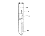
前記漢方用刺針器は、図1に示すように、多数の針が一列に並んで貯蔵され、貯蔵された多数の針を針突出部55の方向に押し出す針移動手段51と、針貯蔵部60に貯蔵された多数の針70のなかで一つを針突出部55の方向に押し出して施術部位に刺針する施術操作部80とを含むことを特徴とする。
しかし、このような従来の漢方用連続刺針器は、多数の針70を一列に貯蔵するから、そのサイズが大きくて使用者が片手で把持して使用するのに非常に不便であるという問題点があった。
また、前記従来の漢方用連続刺針器は、針の貯蔵の際、個々の針70を1本ずつ一列に配列して貯蔵しなければならないため、多くの努力と時間が必要となる問題点もあった。
そして、前記従来の漢方用連続刺針器は、既存の針管を使用するときのように、針70を徐々に患部に突き刺して施術するので、突き刺し速度が遅くて、刺針の際、痛症を誘発する問題点もあった。
As shown in FIG. 1, the traditional Chinese stabbing device stores a large number of needles in a line and stores a needle moving means 51 that pushes the stored many needles in the direction of the
However, since the conventional continuous needle acupuncture device for traditional Chinese medicine stores a large number of
In addition, since the conventional continuous needle acupuncture device for traditional Chinese medicine has to store the
The conventional continuous needle instrument for traditional Chinese medicine uses the
したがって、本発明は前記のような従来の問題点に鑑みてなされたもので、その目的は、片手で把持して施術するのに便利なペンタイプで、封筒に入れられた針を無作為にカートリッジに投入し、無秩序に貯蔵された針を使用者が片手の操作だけでボタンを押して刺針することになるので、使用が非常に便利で、刺針時間を節減することができる連続式刺針器を提供することにある。
本発明の他の目的は、患者には針が見えなくて、施術前の恐れから脱することができ、瞬間的な打撃で痛症なしに刺針するための連続式刺針器を提供することにある。
本発明のさらに他の目的は、連結された刺針点検出装置によって正確な刺針点の位置に施術することができる連続式刺針器を提供することにある。
Therefore, the present invention has been made in view of the above-described conventional problems, and the purpose thereof is a pen type that is convenient for grasping with one hand and performing treatment, and randomly placing a needle in an envelope. The needle inserted into the cartridge and stored randomly is pushed by the user with a single hand operation and the needle is inserted, so it is very convenient to use, and a continuous needle instrument that can save needle time It is to provide.
Another object of the present invention is to provide a continuous puncture device for puncturing needles without any pain by momentary striking, so that the patient can not see the needle and can get rid of fear before surgery. is there.
Still another object of the present invention is to provide a continuous puncture device capable of performing treatment at an accurate puncture point position by a connected puncture point detection device.
前記目的を達成するため、本発明の一観点によれば、身体の患部に針を連続的に刺針する連続式刺針器において、1本以上の針が投入されて貯蔵されるカートリッジと、前記カートリッジの一側に位置し、貯蔵された針を磁力により引き寄せて打撃位置に自動的に配置させる第1磁石と、前記カートリッジの上側に位置し、打撃位置の針を患部に刺針するように打撃する打撃手段と、前記カートリッジの下側に位置し、打撃された針が排出されるホールが形成された排出部と、を含んでなることを特徴とする、連続式刺針器を提供する。
本発明によれば、前記カートリッジの上側に位置し、貯蔵された針の尖端が底に触れないように浮上させる第2磁石をさらに含むことが望ましい。
本発明によれば、前記カートリッジには、針貯蔵空間の一側に針を1本ずつ導入するスロットが形成され、このスロットの端部には、打撃された針が円滑に排出されるようにする排出孔が形成されたことが望ましい。
本発明によれば、前記排出部に出没可能に結合され、突出長によって患部に刺し込まれる針の深さを調節するガイドをさらに含むことが望ましい。
本発明によれば、一側端子は前記排出部に形成され、他側端子は患者の身体一部に接触するように構成された刺針点検出装置をさらに含むことが望ましい。
本発明によれば、前記打撃手段は、カートリッジの上側に、復元スプリングによって上方に弾支されるように取り付けられたボタンと、前記ボタンの内部に、打撃スプリングによって下方に弾支されるように取り付けられた撃針と、前記撃針の一側に形成され、傾斜面を有する撃針鼻部と、前記撃針鼻部の下側にボタンを押すとき、前記撃針鼻部が掛かって一定位置まで打撃スプリングを圧縮させるように形成された圧縮突部と、前記撃針鼻部と接触するように形成され、前記打撃スプリングが一定長さ以上に圧縮されたとき、前記撃針鼻部の傾斜面を押して前記撃針鼻部を圧縮突部から離脱させる解除突部とを含むことが望ましい。
本発明によれば、前記打撃手段は、施術者によって操作されるスイッチと、前記スイッチの作動によって電源を受けて駆動されるアクチュエータと、前記アクチュエータによって昇降しながら針を患部に打撃する撃針とを含むことが望ましい。
To achieve the above object, according to one aspect of the present invention, in a continuous puncture device for continuously piercing a needle into an affected part of a body, a cartridge in which one or more needles are inserted and stored, and the cartridge A first magnet that is located on one side and that attracts the stored needle by a magnetic force and automatically places it in the striking position, and is located on the upper side of the cartridge and strikes the needle at the striking position so as to pierce the affected area There is provided a continuous puncture device comprising striking means and a discharge portion which is located on the lower side of the cartridge and in which a hole for discharging a hit needle is formed.
According to the present invention, it is preferable to further include a second magnet that is located above the cartridge and floats so that the tip of the stored needle does not touch the bottom.
According to the present invention, the cartridge is formed with a slot for introducing one needle at a time into one side of the needle storage space, and the struck needle is smoothly discharged at the end of the slot. It is desirable that a discharge hole is formed.
According to the present invention, it is preferable to further include a guide that is detachably coupled to the discharge portion and adjusts the depth of the needle inserted into the affected portion by the protruding length.
According to the present invention, it is preferable that the one-side terminal is formed on the discharge portion, and the other-side terminal further includes a puncture point detecting device configured to contact a part of the patient's body.
According to the present invention, the hitting means is mounted on the upper side of the cartridge so as to be elastically supported upward by the restoring spring, and inside the button so as to be elastically supported downward by the impact spring. When the button is pushed to the lower side of the shooter nose part, the shooter nose part formed on one side of the attached shooter needle, and having an inclined surface, the shooter nose part is hooked and the hitting spring is moved to a certain position. A compression projection formed to be compressed and formed so as to come into contact with the shooter nose, and when the impact spring is compressed over a certain length, the inclined surface of the shooter nose is pushed to press the shooter nose It is desirable to include a release protrusion that separates the part from the compression protrusion.
According to the present invention, the striking means includes a switch operated by a practitioner, an actuator driven by receiving power by actuation of the switch, and a striking needle for striking the affected part while moving up and down by the actuator. It is desirable to include.
本発明は、無秩序に針を貯蔵した状態で、片手でボタンを押して連続的に刺針を行うことにより、刺針時間を節減するのはもちろん、使用者が便利でかつ衛生的に施術できるようにし、患者には針が見えないので、施術前の恐れから脱することができ、刺針の際、瞬間的な打撃方式により痛症を軽減させることができる。 The present invention, in a state where the needles are stored in a disorderly manner, by pushing the button with one hand and continuously performing the piercing needle, as well as saving the needle time, allowing the user to perform the operation conveniently and hygienically, Since the patient cannot see the needle, he can escape from the fear before the operation, and the pain can be alleviated by a momentary striking method when the needle is inserted.
以下、添付図面に基づいて、本発明の好ましい実施例を説明する。 Hereinafter, preferred embodiments of the present invention will be described with reference to the accompanying drawings.
本発明の一実施例による連続式刺針器について、図2〜図7を参照して説明すれば次のようである。
この連続式刺針器は、使用者の便宜性と衛生を考慮して、針を滅菌封筒から直接無秩序な状態にカートリッジ10に投入しても、順次打撃位置に自動でローディングされるようにすることが技術の核心であり、その形態がペンタイプである場合に最も効果的である。
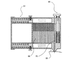
このための構成としては、無秩序な状態に貯蔵された針を1本ずつ打撃位置に自動でローディングさせるための第1磁石1と第2磁石2がカートリッジ10の一側と上側にそれぞれ配置され、このカートリッジ10の上部と下部には、ローディングされた一つの針を打撃する打撃手段と、打撃された針を円滑に排出する排出部30をそれぞれ備える。
A continuous needle instrument according to an embodiment of the present invention will be described with reference to FIGS.
In consideration of the convenience and hygiene of the user, this continuous puncture device is designed so that the needle is automatically loaded sequentially into the striking position even if the needle is directly placed in a disordered state from the sterilized envelope into the
As a configuration for this, the first magnet 1 and the
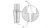
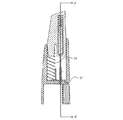
前記カートリッジ10は、図2〜図7に示すように、針貯蔵空間11の一側に、第1磁石1の磁力により針が1本ずつ引き寄せられるスロット14が形成され、このスロット14の端部には、打撃された針を円滑に排出するための排出孔17が形成される。
したがって、前記カートリッジ10は、滅菌された針を、針頭さえ摘まないで封筒から針貯蔵空間11に直接無作為に投入するように構成される。
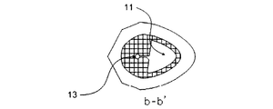
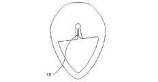
この際、前記スロット14のサイズは針のサイズより少し大きく形成され、その中央部には、1本ずつ引かれてくる針の針頭の下端が掛かる係止段15が形成されることにより、打撃される針が排出孔17を通じて排出されるとき、隣接した針が摩擦力によってともに引かれて排出されないようにする。
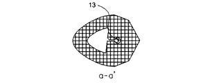
また、打撃された針が排出される排出孔17は、係止段15の下側の下側排出孔13を係止段15の上側の上側排出孔12より大きく形成することで、隣接した針との干渉を避けることが望ましく、下側排出孔13は、針の排出時、隣接した針との干渉を避けえる最小の大きさに形成するために、漏斗状に形成することが望ましい。
As shown in FIGS. 2 to 7, the
Accordingly, the
At this time, the size of the
Further, the
前記第1磁石1は、製品組立ての際、カートリッジ10のスロット14の外側に位置するように、打撃手段のハウジング21に取り付けられるもので、貯蔵された針が磁力により引き寄せられてカートリッジ10の打撃位置に自動でローディングされるようにするものである。
前記第2磁石2は、製品の組立ての際、カートリッジ10の上側に位置するように、打撃手段のハウジング21に取り付けられるもので、磁力によって針が上方に浮上して、針の尖端部が底に接触して損傷することを防止する役目をする。
The first magnet 1 is attached to the
The
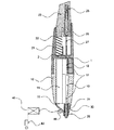
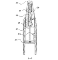
前記打撃手段はカートリッジ10の上側に位置するもので、打撃位置の針を患部に打撃して施術するものである。この際、図10および図11に示すようなスプリング方式の打撃手段は、カートリッジ10の上側に組み立てられるハウジング21と、このハウジング21の内部に、復元スプリング22によって上側に弾支されるように取り付けられたボタン23と、このボタン23の内部に、打撃スプリング25によって下側に弾支された撃針26とから構成される。この撃針26には、打撃位置の針に向かって作動幹27が長く伸びる。この際、前記撃針26は、その下端部一側に、上側に傾斜面が形成された撃針鼻部28が備えられ、これに対応するハウジング21の内部には、ボタン23を押すとき、撃針鼻部28が掛かって一定位置まで打撃スプリング25を圧縮させる圧縮突部21aが形成され、前記撃針鼻部28上側のボタン23の内側には、打撃スプリング25が一定長さ以上に圧縮されたとき、撃針鼻部28の傾斜面を押し付けて、撃針鼻部28を圧縮突部21aから離脱させる解除突部29が備えられる。
The striking means is located on the upper side of the
また、図12に示すようなアクチュエータ方式の打撃手段は、撃針56が駆動部50の動作により下降しながら針を打撃するもので、前記駆動部50としては、スイッチ52の操作によってバッテリー53から電源を受けて動作するように構成されたソレノイドまたはモーターなどの多様な駆動手段が利用可能である。
The actuator-type hitting means as shown in FIG. 12 hits the needle while the
前記排出部30はカートリッジ10の下側に位置するように組み立てられ、その内部には、打撃された針を排出させるホール31が垂直に貫設され、このホール31には、打撃された針が患部に刺し込まれる深さを調節するガイド35が組み立てられる。この際、ガイド35は排出部30のホール31に螺合されて、下側に突出する長さを調節することにより、針の刺し込み深さを調節するように構成される。
The
前記刺針点検出装置40は人体のインピーダンスを測定して患部の刺針点を感知するためのもので、一側端子43は患者の身体一部に接触され、他側端子45は導電性材質のガイド35に形成され、このガイド35を患部に沿って移しながら刺針点位置を易しく捜し出すようにするものである。
The puncture
以上の構成による好ましい実施例の作動メカニズムについて説明すれば次のようである。
前記連続式刺針器は、カートリッジ10に滅菌された針を無作為に投入し、その投入口18に排出部30を結合し、投入口18を閉めた後、前記カートリッジ10の上側に打撃手段を結合すれば、組立てが完了する。
この状態で、前記排出部30を患部に当て、図11のボタン23を押して一定長さ以上に下降させれば、ボタン23の内部の撃針鼻部28が圧縮突部21aに掛かって、撃針26を弾支する打撃スプリング25を圧縮させ、このボタン23を一定長さだけさらに下降させれば、撃針鼻部28の傾斜面が解除突部29によって押されて圧縮突部21aから解除され、打撃スプリング25の弾性力により撃針26を発射させて、打撃位置の1本の針を瞬間的に打撃することになる。このように、高速で瞬間的に打撃することにより、施術による痛症を減らすことができる。これは、既存の針管を利用して打撃する方式に比べ、打撃速度が速いから、刺針の際、優れた痛症減少の効果を提供する。
また、撃針26により打撃された針は、針頭の摩擦力により、隣接した針をともに引いて排出部30側に下がろうとするが、隣接した針は、スロット14の内側に形成された係止段15に針頭が掛かるため、ともに引き下げられない。
The operation mechanism of the preferred embodiment having the above configuration will be described as follows.
The continuous puncture device randomly inserts a sterilized needle into the
In this state, if the
Further, the needle hit by the impacting
打撃の後、連続式刺針器を患部から持ち上げれば、針は刺針器から排出されて患部に突き刺されたままで残ることになる。この際、前記カートリッジ10に形成された排出孔17は、下側排出孔13が上側排出孔12より大きく形成されて、隣接した針線との干渉を避ける構造になっているので、刺針器を持ち上げるとき、刺針された針が抜かれず、刺針された状態をそのままに維持することになる。
ついで、押されたボタン23を放すと、撃針26は復元スプリング22により元の状態に戻り、待機している他の1本の針が、第1磁石1の磁力により、打撃位置に自動で引き寄せられてローディングされるものである。
前述した過程を繰り返すことにより、1本以上の針を連続的に刺針することができることになる。
If the continuous puncture device is lifted from the affected area after the impact, the needle is ejected from the puncture device and remains stuck in the affected area. At this time, the
Next, when the pressed
By repeating the above-described process, one or more needles can be continuously inserted.
前記のような本発明によれば、1本以上の針をカートリッジの内部に便利で衛生的でかつ迅速に装填することができ、色々の針を使用者が短時間に順次連続的に刺針することができる効果がある。
そして、被施術者には、施術前に針が見えないので、漠然たる恐れから脱することができ、瞬間的な打撃により、痛症なしに施術することができる効果がある。
以上、本発明の好ましい実施例を例示的に説明したが、当業者であれば、特許請求範囲い開示された本発明の精神および範囲から逸脱せず、多様な変形、付加および代替が可能であろう。
According to the present invention as described above, one or more needles can be conveniently, hygienically and quickly loaded inside the cartridge, and the user sequentially and continuously inserts various needles in a short time. There is an effect that can.
In addition, since the needle is not visible to the patient before the operation, there is an effect that it is possible to escape from vague fears and to perform the operation without pain by instantaneous impact.
Although the preferred embodiments of the present invention have been described by way of example, those skilled in the art can make various modifications, additions and alternatives without departing from the spirit and scope of the present invention disclosed in the claims. I will.
1 第1磁石
2 第2磁石
10 カートリッジ
11 針貯蔵空間
14 スロット
17 排出孔
21 ハウジング
22 復元スプリング
23 ボタン
25 打撃スプリング
26 撃針
30 排出部
35 ガイド
40 刺針点検出装置
DESCRIPTION OF SYMBOLS 1
Claims (7)
1本以上の針が投入されて貯蔵されるカートリッジと、
前記カートリッジの一側に位置し、貯蔵された針を磁力により引き寄せて打撃位置に自動的に配置させるる第1磁石と、
前記カートリッジの上側に位置し、打撃位置の針を患部に刺針するように打撃する打撃手段と、
前記カートリッジの下側に位置し、打撃された針が排出されるホールが形成された排出部と、を含んでなることを特徴とする、連続式刺針器。 In a continuous puncture device that continuously pierces the affected part of the body,
A cartridge in which one or more needles are loaded and stored;
A first magnet located on one side of the cartridge for pulling the stored needles magnetically and automatically placing them in the striking position;
A striking means for striking the needle at the striking position so as to pierce the affected area, located above the cartridge;
A continuous puncture device comprising: a discharge portion which is located on a lower side of the cartridge and in which a hole for discharging a hit needle is formed.
カートリッジの上側に、復元スプリングによって上方に弾支されるように取り付けられたボタンと、
前記ボタンの内部に、打撃スプリングによって下方に弾支されるように取り付けられた撃針と、
前記撃針の一側に形成され、傾斜面を有する撃針鼻部と、
前記撃針鼻部の下側にボタンを押すとき、前記撃針鼻部が掛かって一定位置まで打撃スプリングを圧縮させるように形成された圧縮突部と、
前記撃針鼻部と接触するように形成され、前記打撃スプリングが一定長さ以上に圧縮されたとき、前記撃針鼻部の傾斜面を押して前記撃針鼻部を圧縮突部から離脱させる解除突部と、を含むことを特徴とする、請求項1に記載の連続式刺針器。 The hitting means is
A button attached to the upper side of the cartridge so as to be elastically supported upward by a restoring spring;
A firing needle attached to the inside of the button so as to be supported by a striking spring downward,
A shooter nose portion formed on one side of the shooter and having an inclined surface;
A compression projection formed to compress the striking spring to a certain position when the button is pressed on the lower side of the firing pin nose,
A release protrusion formed so as to come into contact with the firing needle nose, and when the impact spring is compressed to a predetermined length or longer, a release protrusion that pushes an inclined surface of the firing needle nose to release the firing needle nose from the compression protrusion; The continuous puncture device according to claim 1, comprising:
施術者によって操作されるスイッチと、
前記スイッチの作動によって電源を受けて駆動されるアクチュエータと、
前記アクチュエータによって昇降しながら針を患部に打撃する撃針とを含むことを特徴とする、請求項1に記載の連続式刺針器。 The hitting means is
A switch operated by the practitioner;
An actuator that is driven by receiving power by operating the switch;
The continuous needle puncture device according to claim 1, comprising a firing needle that strikes an affected part while moving up and down by the actuator.
Applications Claiming Priority (3)
| Application Number | Priority Date | Filing Date | Title |
|---|---|---|---|
| KR1020050019665A KR100553006B1 (en) | 2005-03-09 | 2005-03-09 | Automatic acupuncture device |
| KR1020050126146A KR100585844B1 (en) | 2005-12-20 | 2005-12-20 | Consecutive acupuncture device |
| PCT/KR2006/000520 WO2006095966A1 (en) | 2005-03-09 | 2006-02-14 | Consecutive acupuncture device |
Publications (2)
| Publication Number | Publication Date |
|---|---|
| JP2008519645A true JP2008519645A (en) | 2008-06-12 |
| JP4443610B2 JP4443610B2 (en) | 2010-03-31 |
Family
ID=36953536
Family Applications (1)
| Application Number | Title | Priority Date | Filing Date |
|---|---|---|---|
| JP2007541115A Active JP4443610B2 (en) | 2005-03-09 | 2006-02-14 | Continuous needle |
Country Status (6)
| Country | Link |
|---|---|
| US (1) | US8038695B2 (en) |
| EP (1) | EP1858473B1 (en) |
| JP (1) | JP4443610B2 (en) |
| CN (1) | CN101137342B (en) |
| BR (1) | BRPI0606230A2 (en) |
| WO (1) | WO2006095966A1 (en) |
Cited By (1)
| Publication number | Priority date | Publication date | Assignee | Title |
|---|---|---|---|---|
| JP2010533538A (en) * | 2007-07-18 | 2010-10-28 | ネオ ドクター インコーポレイテッド | Continuous acupuncture device and continuous acupuncture device cartridge |
Families Citing this family (9)
| Publication number | Priority date | Publication date | Assignee | Title |
|---|---|---|---|---|
| US8540645B2 (en) * | 2011-07-27 | 2013-09-24 | Suros Surgical Systems, Inc. | Needle biopsy device and related method |
| CN103751017B (en) * | 2013-12-29 | 2018-06-08 | 湖南中医药大学 | Acupuncture needle quick needle insertion pen |
| CN108785070A (en) * | 2017-05-04 | 2018-11-13 | 庆名医疗器材有限公司 | Acupuncture and moxibustion device |
| CN109248089B (en) * | 2018-11-23 | 2021-10-26 | 叶春生 | Pen type thumb push needle acupuncture needle inserting device |
| CN109552766B (en) * | 2019-01-13 | 2019-12-13 | 山东中医药大学 | medical acupuncture needle ejector |
| CN110037919B (en) * | 2019-05-16 | 2024-01-30 | 北京积水潭医院 | Acupuncture needle extractor |
| CN112120931B (en) * | 2020-09-29 | 2022-06-03 | 刁雅静 | Adjustable self-heating acupuncture needle |
| US11504299B2 (en) * | 2020-10-12 | 2022-11-22 | Wellness Allied Inc | Automatic acupuncture device, needle gadget and acupuncture method |
| CN114028223A (en) * | 2021-12-26 | 2022-02-11 | 安徽中医药大学 | Aseptically-packaged acupuncture needle box and acupuncture needle inserting device |
Family Cites Families (13)
| Publication number | Priority date | Publication date | Assignee | Title |
|---|---|---|---|---|
| US4580566A (en) * | 1982-04-22 | 1986-04-08 | Hsu John J | Acupuncture needle and needle guide assembly |
| FR2571251B1 (en) * | 1984-08-07 | 1989-12-15 | Scieller Jean Xavier | MODULAR DEVICE WITH DISPENSER FOR THE PAINLESS APPLICATION OF STERILE ACUPUNCTURE NEEDLES |
| KR950000061B1 (en) * | 1992-05-28 | 1995-01-09 | 재단법인 한국화학연구소 | Acupuncture |
| KR950010633B1 (en) * | 1992-07-13 | 1995-09-21 | 석풍장 | Tube with needle keeping vessel |
| US6113620A (en) * | 1996-07-12 | 2000-09-05 | Il Yang Pharm. Co., Ltd. | Magnetic needle for acupuncture |
| US5954738A (en) * | 1997-07-31 | 1999-09-21 | Bayer Corporation | Blood sampling device with lancet damping system |
| US6719765B2 (en) * | 2001-12-03 | 2004-04-13 | Bonutti 2003 Trust-A | Magnetic suturing system and method |
| KR100497115B1 (en) * | 2002-07-18 | 2005-06-28 | 추래흥 | The apparatus of continuous pricking needles for a herb doctor |
| US7240806B2 (en) * | 2003-09-25 | 2007-07-10 | Choi Jeung H | Acupuncture needle container and dispenser |
| US20050277973A1 (en) * | 2004-06-01 | 2005-12-15 | Joseph Huang | Ultrasonic pigment application device |
| US7470237B2 (en) * | 2005-01-10 | 2008-12-30 | Ethicon Endo-Surgery, Inc. | Biopsy instrument with improved needle penetration |
| US20060247671A1 (en) * | 2005-05-02 | 2006-11-02 | Levaughn Richard W | Compact, multi-use micro-sampling device |
| ES2326699T3 (en) * | 2007-03-14 | 2009-10-16 | F. Hoffmann-La Roche Ag | LANCETA DEVICE. |
-
2006
- 2006-02-14 CN CN2006800072501A patent/CN101137342B/en not_active Expired - Fee Related
- 2006-02-14 JP JP2007541115A patent/JP4443610B2/en active Active
- 2006-02-14 BR BRPI0606230-0A patent/BRPI0606230A2/en not_active IP Right Cessation
- 2006-02-14 EP EP06715971A patent/EP1858473B1/en not_active Not-in-force
- 2006-02-14 US US11/718,818 patent/US8038695B2/en active Active
- 2006-02-14 WO PCT/KR2006/000520 patent/WO2006095966A1/en active Application Filing
Cited By (1)
| Publication number | Priority date | Publication date | Assignee | Title |
|---|---|---|---|---|
| JP2010533538A (en) * | 2007-07-18 | 2010-10-28 | ネオ ドクター インコーポレイテッド | Continuous acupuncture device and continuous acupuncture device cartridge |
Also Published As
| Publication number | Publication date |
|---|---|
| WO2006095966A8 (en) | 2011-10-20 |
| JP4443610B2 (en) | 2010-03-31 |
| EP1858473A1 (en) | 2007-11-28 |
| CN101137342B (en) | 2011-08-24 |
| EP1858473B1 (en) | 2012-08-29 |
| EP1858473A4 (en) | 2011-08-10 |
| BRPI0606230A2 (en) | 2009-06-09 |
| US20080097505A1 (en) | 2008-04-24 |
| CN101137342A (en) | 2008-03-05 |
| WO2006095966A1 (en) | 2006-09-14 |
| US8038695B2 (en) | 2011-10-18 |
Similar Documents
| Publication | Publication Date | Title |
|---|---|---|
| JP4443610B2 (en) | Continuous needle | |
| CN216222323U (en) | Automatic acupuncture device and acupuncture set | |
| JP3647738B2 (en) | Electronic puncture device | |
| US7927345B2 (en) | Lancet cartridges and lancing devices | |
| US4416279A (en) | Capillary blood sampling device | |
| KR200315777Y1 (en) | Lancing device | |
| CN107072605B (en) | Bullet formula blood sampling pen structure of unloading | |
| KR101847548B1 (en) | Atomatic Acupuncture Apparatus | |
| KR102277465B1 (en) | Blood lancet | |
| US11284868B2 (en) | Multi-function dermatological biopsy instrument | |
| KR100585844B1 (en) | Consecutive acupuncture device | |
| TWM513008U (en) | High-speed lancing device with lancet ejection means | |
| CN107405119A (en) | A kind of safety type blood collecting needle construction | |
| CN203724457U (en) | Continuous quick acupuncture needle inserter | |
| JP2009505718A (en) | Device to pierce the patient's skin | |
| CN204636384U (en) | A kind of bullet unloads formula blood collecting pen structure | |
| KR200410109Y1 (en) | Consecutive acupuncture device | |
| KR200478011Y1 (en) | Elasticity insertion instrument for embedding thread | |
| CN107260185B (en) | Striker self-rebound mechanism for blood collection needle | |
| CN110464363A (en) | Reduce the blood collecting pen for puncturing pain | |
| EP3808394A1 (en) | Syringe device | |
| CN107334479B (en) | Ejection control mechanism for blood taking needle | |
| CN211187367U (en) | Nose bulking imbedding device | |
| KR20210091844A (en) | Tool of Depletion | |
| CN219071260U (en) | Floating needle inserting device capable of preventing floating needle from separating |
Legal Events
| Date | Code | Title | Description |
|---|---|---|---|
| A131 | Notification of reasons for refusal |
Free format text: JAPANESE INTERMEDIATE CODE: A131 Effective date: 20090810 |
|
| A521 | Request for written amendment filed |
Free format text: JAPANESE INTERMEDIATE CODE: A523 Effective date: 20091109 |
|
| TRDD | Decision of grant or rejection written | ||
| A01 | Written decision to grant a patent or to grant a registration (utility model) |
Free format text: JAPANESE INTERMEDIATE CODE: A01 Effective date: 20091215 |
|
| A01 | Written decision to grant a patent or to grant a registration (utility model) |
Free format text: JAPANESE INTERMEDIATE CODE: A01 |
|
| A61 | First payment of annual fees (during grant procedure) |
Free format text: JAPANESE INTERMEDIATE CODE: A61 Effective date: 20100112 |
|
| R150 | Certificate of patent or registration of utility model |
Ref document number: 4443610 Country of ref document: JP Free format text: JAPANESE INTERMEDIATE CODE: R150 |
|
| FPAY | Renewal fee payment (event date is renewal date of database) |
Free format text: PAYMENT UNTIL: 20130122 Year of fee payment: 3 |
|
| FPAY | Renewal fee payment (event date is renewal date of database) |
Free format text: PAYMENT UNTIL: 20140122 Year of fee payment: 4 |
|
| R250 | Receipt of annual fees |
Free format text: JAPANESE INTERMEDIATE CODE: R250 |
|
| R250 | Receipt of annual fees |
Free format text: JAPANESE INTERMEDIATE CODE: R250 |
|
| R250 | Receipt of annual fees |
Free format text: JAPANESE INTERMEDIATE CODE: R250 |
|
| R250 | Receipt of annual fees |
Free format text: JAPANESE INTERMEDIATE CODE: R250 |
|
| R250 | Receipt of annual fees |
Free format text: JAPANESE INTERMEDIATE CODE: R250 |
|
| R250 | Receipt of annual fees |
Free format text: JAPANESE INTERMEDIATE CODE: R250 |
|
| R250 | Receipt of annual fees |
Free format text: JAPANESE INTERMEDIATE CODE: R250 |
|
| R250 | Receipt of annual fees |
Free format text: JAPANESE INTERMEDIATE CODE: R250 |
|
| R250 | Receipt of annual fees |
Free format text: JAPANESE INTERMEDIATE CODE: R250 |
|
| R250 | Receipt of annual fees |
Free format text: JAPANESE INTERMEDIATE CODE: R250 |
|
| R250 | Receipt of annual fees |
Free format text: JAPANESE INTERMEDIATE CODE: R250 |
|
| R250 | Receipt of annual fees |
Free format text: JAPANESE INTERMEDIATE CODE: R250 |