JP2008510179A - Communication cable enclosure - Google Patents
Communication cable enclosure Download PDFInfo
- Publication number
- JP2008510179A JP2008510179A JP2007525612A JP2007525612A JP2008510179A JP 2008510179 A JP2008510179 A JP 2008510179A JP 2007525612 A JP2007525612 A JP 2007525612A JP 2007525612 A JP2007525612 A JP 2007525612A JP 2008510179 A JP2008510179 A JP 2008510179A
- Authority
- JP
- Japan
- Prior art keywords
- enclosure
- terminal
- housing
- closure
- port
- Prior art date
- Legal status (The legal status is an assumption and is not a legal conclusion. Google has not performed a legal analysis and makes no representation as to the accuracy of the status listed.)
- Pending
Links
- 238000004891 communication Methods 0.000 title claims abstract description 77
- 238000007789 sealing Methods 0.000 claims description 26
- 239000013307 optical fiber Substances 0.000 claims description 22
- 239000000835 fiber Substances 0.000 claims description 18
- 230000013011 mating Effects 0.000 claims description 14
- RYGMFSIKBFXOCR-UHFFFAOYSA-N Copper Chemical compound [Cu] RYGMFSIKBFXOCR-UHFFFAOYSA-N 0.000 claims description 7
- 230000003287 optical effect Effects 0.000 claims description 7
- 239000010949 copper Substances 0.000 claims description 6
- 229910052802 copper Inorganic materials 0.000 claims description 6
- 239000013013 elastic material Substances 0.000 claims 1
- 239000000428 dust Substances 0.000 description 7
- 239000002861 polymer material Substances 0.000 description 4
- 241000238631 Hexapoda Species 0.000 description 3
- 230000006835 compression Effects 0.000 description 3
- 238000007906 compression Methods 0.000 description 3
- 239000000463 material Substances 0.000 description 3
- 238000000034 method Methods 0.000 description 3
- 238000000465 moulding Methods 0.000 description 3
- 238000000926 separation method Methods 0.000 description 3
- 238000003860 storage Methods 0.000 description 3
- 239000004698 Polyethylene Substances 0.000 description 2
- 238000000071 blow moulding Methods 0.000 description 2
- 238000004140 cleaning Methods 0.000 description 2
- 239000004020 conductor Substances 0.000 description 2
- 239000000356 contaminant Substances 0.000 description 2
- 239000006185 dispersion Substances 0.000 description 2
- 238000009826 distribution Methods 0.000 description 2
- 238000001746 injection moulding Methods 0.000 description 2
- 238000003780 insertion Methods 0.000 description 2
- 238000005304 joining Methods 0.000 description 2
- 230000002093 peripheral effect Effects 0.000 description 2
- -1 polyethylene Polymers 0.000 description 2
- 229920000573 polyethylene Polymers 0.000 description 2
- 229920002725 thermoplastic elastomer Polymers 0.000 description 2
- 229920006342 thermoplastic vulcanizate Polymers 0.000 description 2
- XLYOFNOQVPJJNP-UHFFFAOYSA-N water Substances O XLYOFNOQVPJJNP-UHFFFAOYSA-N 0.000 description 2
- 238000003466 welding Methods 0.000 description 2
- 230000015556 catabolic process Effects 0.000 description 1
- 230000008878 coupling Effects 0.000 description 1
- 238000010168 coupling process Methods 0.000 description 1
- 238000005859 coupling reaction Methods 0.000 description 1
- 238000006731 degradation reaction Methods 0.000 description 1
- 229920001971 elastomer Polymers 0.000 description 1
- 238000001914 filtration Methods 0.000 description 1
- 230000037431 insertion Effects 0.000 description 1
- 238000009434 installation Methods 0.000 description 1
- 238000002955 isolation Methods 0.000 description 1
- WABPQHHGFIMREM-UHFFFAOYSA-N lead(0) Chemical compound [Pb] WABPQHHGFIMREM-UHFFFAOYSA-N 0.000 description 1
- 238000012986 modification Methods 0.000 description 1
- 230000004048 modification Effects 0.000 description 1
- 230000003252 repetitive effect Effects 0.000 description 1
- 239000012858 resilient material Substances 0.000 description 1
- 230000000717 retained effect Effects 0.000 description 1
- 230000035945 sensitivity Effects 0.000 description 1
Images


Classifications
-
- H—ELECTRICITY
- H01—ELECTRIC ELEMENTS
- H01L—SEMICONDUCTOR DEVICES NOT COVERED BY CLASS H10
- H01L29/00—Semiconductor devices specially adapted for rectifying, amplifying, oscillating or switching and having potential barriers; Capacitors or resistors having potential barriers, e.g. a PN-junction depletion layer or carrier concentration layer; Details of semiconductor bodies or of electrodes thereof ; Multistep manufacturing processes therefor
- H01L29/40—Electrodes ; Multistep manufacturing processes therefor
- H01L29/43—Electrodes ; Multistep manufacturing processes therefor characterised by the materials of which they are formed
- H01L29/49—Metal-insulator-semiconductor electrodes, e.g. gates of MOSFET
-
- G—PHYSICS
- G02—OPTICS
- G02B—OPTICAL ELEMENTS, SYSTEMS OR APPARATUS
- G02B6/00—Light guides; Structural details of arrangements comprising light guides and other optical elements, e.g. couplings
- G02B6/44—Mechanical structures for providing tensile strength and external protection for fibres, e.g. optical transmission cables
- G02B6/4439—Auxiliary devices
- G02B6/444—Systems or boxes with surplus lengths
- G02B6/44528—Patch-cords; Connector arrangements in the system or in the box
-
- H—ELECTRICITY
- H01—ELECTRIC ELEMENTS
- H01L—SEMICONDUCTOR DEVICES NOT COVERED BY CLASS H10
- H01L29/00—Semiconductor devices specially adapted for rectifying, amplifying, oscillating or switching and having potential barriers; Capacitors or resistors having potential barriers, e.g. a PN-junction depletion layer or carrier concentration layer; Details of semiconductor bodies or of electrodes thereof ; Multistep manufacturing processes therefor
- H01L29/40—Electrodes ; Multistep manufacturing processes therefor
- H01L29/43—Electrodes ; Multistep manufacturing processes therefor characterised by the materials of which they are formed
- H01L29/49—Metal-insulator-semiconductor electrodes, e.g. gates of MOSFET
- H01L29/51—Insulating materials associated therewith
-
- H—ELECTRICITY
- H02—GENERATION; CONVERSION OR DISTRIBUTION OF ELECTRIC POWER
- H02G—INSTALLATION OF ELECTRIC CABLES OR LINES, OR OF COMBINED OPTICAL AND ELECTRIC CABLES OR LINES
- H02G15/00—Cable fittings
- H02G15/08—Cable junctions
- H02G15/10—Cable junctions protected by boxes, e.g. by distribution, connection or junction boxes
- H02G15/117—Cable junctions protected by boxes, e.g. by distribution, connection or junction boxes for multiconductor cables
-
- G—PHYSICS
- G02—OPTICS
- G02B—OPTICAL ELEMENTS, SYSTEMS OR APPARATUS
- G02B6/00—Light guides; Structural details of arrangements comprising light guides and other optical elements, e.g. couplings
- G02B6/24—Coupling light guides
- G02B6/36—Mechanical coupling means
- G02B6/38—Mechanical coupling means having fibre to fibre mating means
- G02B6/3807—Dismountable connectors, i.e. comprising plugs
- G02B6/3897—Connectors fixed to housings, casing, frames or circuit boards
-
- G—PHYSICS
- G02—OPTICS
- G02B—OPTICAL ELEMENTS, SYSTEMS OR APPARATUS
- G02B6/00—Light guides; Structural details of arrangements comprising light guides and other optical elements, e.g. couplings
- G02B6/44—Mechanical structures for providing tensile strength and external protection for fibres, e.g. optical transmission cables
- G02B6/4439—Auxiliary devices
- G02B6/444—Systems or boxes with surplus lengths
- G02B6/4441—Boxes
- G02B6/445—Boxes with lateral pivoting cover
Landscapes
- Physics & Mathematics (AREA)
- General Physics & Mathematics (AREA)
- Engineering & Computer Science (AREA)
- Microelectronics & Electronic Packaging (AREA)
- Power Engineering (AREA)
- Optics & Photonics (AREA)
- Ceramic Engineering (AREA)
- Condensed Matter Physics & Semiconductors (AREA)
- Computer Hardware Design (AREA)
- Light Guides In General And Applications Therefor (AREA)
- Cable Accessories (AREA)
- Structure Of Telephone Exchanges (AREA)
Abstract
通信ケーブルと共に用いるためのエンクロージャは、スプライス接続された通信回線を保持するためのハウジングを含む。少なくとも1つの複数の接続素子は、ハウジングの中でスプライス接続された通信回線の1つに接続される。ハウジングにおける主要な入口は、ハウジングにおいて複数の接続素子のそれぞれへの同時アクセスを可能にする。ハウジングの壁に一体に形成されるアダプタにより、ハウジングの外部からハウジングの壁を通って複数の接続素子のうちの1つのアクセスおよび取り出しを可能にする。 An enclosure for use with a communication cable includes a housing for holding a spliced communication line. At least one of the plurality of connecting elements is connected to one of the communication lines spliced in the housing. The main inlet in the housing allows simultaneous access to each of the plurality of connecting elements in the housing. An adapter integrally formed on the housing wall allows access and removal of one of the plurality of connecting elements through the housing wall from the outside of the housing.
Description
本発明は一般に、通信ケーブル用のエンクロージャに関する。さらに詳細には、本発明は、エンクロージャの外部からエンクロージャの壁を通して接続素子の取り出しを可能にするように構成された通信エンクロージャに関する。 The present invention generally relates to an enclosure for communication cables. More particularly, the present invention relates to a communication enclosure configured to allow removal of connecting elements from the exterior of the enclosure through the enclosure wall.
通信ケーブルは、至る所に存在し、広大なネットワークにわたってあらゆる態様のデータを分散するために用いられる。通信ケーブルの大部分は、導電性ケーブル(一般に銅)であるが、ますます大量のデータが伝送されるにつれて、光ファイバケーブルの利用が急速に増大しつつある。通信ケーブルがネットワークにわたって経路指定されるとき、ケーブルおよびスプライスを定期的に開放するか、またはケーブルにタップ接続して、データがネットワークの「分岐」に分散されることができるようにすることが必要である。ネットワークが個々の家庭、会社、オフィスなどに達するまで、分岐をさらに分散することができる。分散線は、引込線または配電線と呼ばれることが多い。ケーブルが開放される各点では、ケーブルを保護するためのある種のエンクロージャを設けることが必要である。エンクロージャによりケーブルに容易かつ反復してアクセスすることができ、技術者が任意の必要なサービスを提供するためにケーブルに容易にアクセスしやすいようになっていることが好ましい。 Communication cables are ubiquitous and are used to distribute all aspects of data across a vast network. The majority of communication cables are conductive cables (typically copper), but the use of fiber optic cables is rapidly increasing as more and more data is transmitted. When communication cables are routed across the network, the cables and splices must be periodically opened or tapped into the cables to allow data to be distributed to the network “branches” It is. Branches can be further distributed until the network reaches individual homes, businesses, offices, etc. Dispersion lines are often referred to as service lines or distribution lines. At each point where the cable is opened, it is necessary to provide some type of enclosure to protect the cable. Preferably, the enclosure allows easy and repetitive access to the cable so that the technician can easily access the cable to provide any necessary service.
電気通信ケーブルおよび光通信ケーブルの両方用のエンクロージャが一般に周知である。1本以上のケーブルを収容し、ある形態のケーブル接続部(スプライス、コネクタまたは他の接続素子)および余分な長さのケーブルを含むエンクロージャが、周知である。そのようなエンクロージャはまた、未使用の導線または次の使用に待機している光ファイバを格納するための格納手段も含むことが多い。一部のエンクロージャでは、引込線などに次に接続することを意図しているケーブルおよび接続素子におけるスプライスは、エンクロージャの個別の領域で維持され、引込線などを接続するときのエンクロージャへの再挿入中にケーブルスプライスの損傷または破損の可能性を低減するようになっている。しかし、新しい引込線に接続するためにエンクロージャが開放されるとき、引込線接続および関連する光ファイバまたは導線はすべて露出される。 Enclosures for both telecommunications cables and optical communication cables are generally well known. Enclosures that contain one or more cables and contain some form of cable connection (splice, connector or other connection element) and extra length of cable are well known. Such enclosures also often include storage means for storing unused conductors or optical fibers waiting for subsequent use. In some enclosures, splices in cables and connecting elements that are intended to be connected next to service lines, etc. are maintained in separate areas of the enclosure and are reinserted into the enclosure when connecting service lines, etc. It is intended to reduce the possibility of damage or breakage of the cable splice. However, when the enclosure is opened to connect to a new service line, all service line connections and associated optical fibers or conductors are exposed.
従来技術のエンクロージャの大半は、導電性通信ケーブルと共に用いることを意図としており、導電性ケーブルに比べて、異なる構成および性能問題を有する光ファイバケーブルと共に用いることに一般に適していない。たとえば、光ファイバケーブルにおいて用いられる光ファイバは、最小曲げ半径を超えて曲げられる場合には、性能の劣化を生じることが多く、破損することもある。さらに、光ファイバおよびその接続部(スプライス、コネクタまたは他の接続素子)は、物理的な運搬および埃、湿気などのデブリの存在の影響を受けやすい。光ファイバおよびその接続部のこの敏感さのために、引込線などを接続するときのエンクロージャへの再挿入中などに、ファイバまたは接続素子の損傷の可能性が高くなる。 Most prior art enclosures are intended for use with conductive communication cables and are generally not suitable for use with fiber optic cables that have different configuration and performance issues compared to conductive cables. For example, optical fibers used in fiber optic cables often cause performance degradation and can be damaged if they are bent beyond a minimum bend radius. Furthermore, optical fibers and their connections (splices, connectors or other connecting elements) are susceptible to physical transport and the presence of debris such as dust and moisture. This sensitivity of the optical fiber and its connections increases the possibility of damage to the fiber or connecting element, such as during re-insertion into the enclosure when connecting lead wires or the like.
したがって、再挿入中のエンクロージャにおける1つまたは制限された数の光ファイバ接続素子にアクセスする選択肢を可能にし、エンクロージャ中のすべての光ファイバおよび接続素子の露出を必要としない通信ケーブルエンクロージャが、きわめて望ましい。 Thus, communication cable enclosures that allow access to one or a limited number of fiber optic connecting elements in the reinserting enclosure and that do not require exposure of all the optical fibers and connecting elements in the enclosure are extremely desirable.
本願明細書に記載される本発明は、通信ケーブルと共に用いるためのエンクロージャを提供する。本発明による一実施形態において、エンクロージャは、その中に通信ケーブルのスプライス接続された通信回線を保持するためのハウジングを備える。複数の接続素子のうちの少なくとも1つは、ハウジングの中でスプライス接続された通信回線の1つに接続され、ハウジングの外側に延在する通信回線を終端する嵌合接続素子に接続するように構成される。ハウジングにおいて複数の接続素子のそれぞれへの同時アクセスを可能にするハウジングにおける主要な入口およびハウジングの壁に一体に形成されるアダプタにより、ハウジングの外部からハウジングの壁を通って複数の接続素子のうちの1つのアクセスおよび取り出しを可能にする。 The invention described herein provides an enclosure for use with communication cables. In one embodiment according to the present invention, the enclosure comprises a housing for holding a splice-connected communication line of communication cables therein. At least one of the plurality of connection elements is connected to one of the spliced communication lines in the housing and connected to a mating connection element that terminates the communication line extending outside the housing. Composed. An adapter formed integrally with the main inlet and the housing wall in the housing that allows simultaneous access to each of the plurality of connecting elements in the housing, and from among the plurality of connecting elements through the housing wall from the outside of the housing One access and retrieval.
本発明による他の実施形態において、エンクロージャは、通信回線におけるスプライスを保持するためのスプライス区画と、スプライス区画に保持されるスプライスから離れて通信回線接続素子を保持するための端子区画と、を備える。少なくとも1つのポートは、端子区画に隣接するエンクロージャの壁を通って延在する。少なくとも1つのポートは、接続素子を収容して、エンクロージャの外側から壁を通って接続素子の取り出しを可能にするように構成される。 In another embodiment according to the invention, the enclosure comprises a splice section for holding a splice in the communication line and a terminal section for holding the communication line connection element away from the splice held in the splice section. . At least one port extends through the wall of the enclosure adjacent to the terminal compartment. At least one port is configured to receive the connecting element and allow removal of the connecting element through the wall from the outside of the enclosure.
本発明による他の実施形態において、通信ケーブル用の端子は、通信ケーブルのスプライス接続された通信回線を保持するためのスプライスクロージャと、スプライスクロージャに接合される端子クロージャと、を備える。端子クロージャは、スプライスクロージャにおいて対応する通信回線に接続される複数の接続素子を保持するように構成される。少なくとも1つの閉鎖可能なポートは、端子クロージャの外壁を通って延在し、ポートは、端子クロージャの外部からポートを介して接続素子を端子クロージャから引き抜くことが可能であるように構成される。 In another embodiment according to the present invention, a terminal for a communication cable includes a splice closure for holding a communication line spliced to the communication cable and a terminal closure joined to the splice closure. The terminal closure is configured to hold a plurality of connection elements connected to a corresponding communication line in the splice closure. At least one closable port extends through the outer wall of the terminal closure, and the port is configured to allow the connecting element to be pulled out of the terminal closure through the port from outside the terminal closure.
本発明の実施形態は、以下の図面を参照すればより理解される。図面の要素は、互いに対して必ずしも一定の縮尺である必要はない。同様の参照符号は、対応する類似の部分を表す。 Embodiments of the present invention will be better understood with reference to the following drawings. The elements of the drawings do not necessarily have to scale relative to each other. Like reference numerals represent corresponding similar parts.
好ましい実施形態の以下の詳細な説明では、添付図面を参照する。添付図面は、本願明細書の一部をなし、本発明を実施しうる特定の実施形態の実例として示される。たとえば、図1〜図5および関連する詳細な説明は、光ファイバケーブルと共に用いるための端子10を示す。図1〜図5の端子10は、本発明による通信ケーブルエンクロージャの単なる一例示的実施形態であり、本発明による通信ケーブルエンクロージャの実施形態のすべてを網羅することを意図していない。他の実施形態を利用し、本発明の範囲を逸脱することなく、構造的変更または論理的変更を行うことができることを理解されたい。したがって、以下の詳細な説明は限定的な意味で捉えるべきではなく、本発明の範囲は添付の特許請求の範囲によって規定される。
In the following detailed description of the preferred embodiments, reference is made to the accompanying drawings. The accompanying drawings constitute a part of this specification and are shown by way of illustration of specific embodiments in which the invention may be practiced. For example, FIGS. 1-5 and the associated detailed description show a
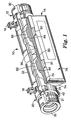
図1および図2を参照すると、端子10は、一体型のスプライスクロージャ12および端子クロージャ14を備える。図示されているように、端子10は、地上(すなわち地面から上)のエンクロージャであり、1対のハンガ16によって支持ケーブル(図示せず)から懸架されるようにさらに構成される。他の実施形態において、端子10は、地下(すなわち地面より下)のエンクロージャであってもよい。
With reference to FIGS. 1 and 2, the
スプライスクロージャ12は、埃、水、虫などがケーシング20の中に侵入するのを制限するためにラビリンス型シールを形成するために、嵌合するねじ山および溝を有する縁または開放シーム21に沿って開放することができるようなケーシング20を備える。一般に、ケーシング20は、蝶番線26に沿って互いに回転可能に接続される第1のケーシング部分22および第2のケーシング部分24を備える。本発明による一実施形態において、蝶番線26は、圧縮成形される蝶番28によって画定される。すなわち、蝶番28は、ケーシング部分22、24と一体である。ケーシング20は、ポリエチレンなどの適切なポリマー材料から成形されることが好ましい。このように、ケーシング20が成形されるとき、蝶番28はケーシング部分22、24と一体成形されてもよい。ケーシング20は、吹込成形、射出成形などの任意の従来の成形技術によって作製されうる。各部分22、24は、ケーシング20の約2分の1である。すなわち、部分22、24のそれぞれは、略半円筒形の構造である。
The
図1において分かるように、ケーシング20は、細長く、略円筒形状であり、第1および第2の対向する端部30、32を有する。端部シール34(図2において最もよく分かる)は、第1の端部30および第2の端部32でケーシング20に入るケーブル(図示せず)を収容し、その周囲を密閉するために、第1の端部30および第2の端部32に配置される。円筒形のケーシング20は、ラッチまたは固締素子40によって閉鎖状態を維持して固定される。固締素子40は、種々の従来の構成のいずれであってもよく、それによって部分22をシーム21に沿って部分24に選択的に固定することができる。図1〜図5に示される実施形態において、固締素子40は、アクチュエータハンドルおよびトグルラッチを形成する固定ラッチを含む。固締素子40のラッチ部分がボス56を部分24に嵌合することができるように、固締素子40は、ケーシング20の部分22に支持される。したがって、必要に応じて、ケーシング20の内部へのアクセスを提供するために、ケーシング20を容易に開閉することができる。
As can be seen in FIG. 1, the
図1および図4を調べれば明白であるように、ケーシング20内部の包囲されたスプライス領域へのアクセスは、第2のケーシング部分24(下部位置)に対する第1のケーシング部分22(上部位置)の回転位置によって容易になる。具体的に言えば、ケーシング20が開放されているとき、ケーシング20の内側のスプライス領域は実質的に妨げられることなく見えるように(図2参照)、ケーシング20の第1の部分22および第2の部分24が向けられる。これは、ハンガ16の位置に対する蝶番線26の好ましい位置決めによって実現される。一実施形態において、蝶番線26は、支持ケーブル(図示せず)に端子10を取付けるために、ハンガ16の取付け点から約125°〜145°、好ましくは約135°で位置決めされる。
As is apparent from an examination of FIGS. 1 and 4, access to the enclosed splice region within the
図2において、スプライスクロージャ12は、ケーシング20が開放位置にある状態を示している。端部シール34は、本願明細書の譲受人に譲渡され、本願明細書に参照によって援用されるものとする米国特許第4,857,672号明細書に基づいて形成されてもよく、部分22の第1の端部30および第2の端部32にある凹部に支持され、その中にケーブルを収容するときに、端部シール34が第1の端部30および第2の端部32にそれぞれ隣接して保持されるようになっている。部分22、24が閉鎖位置にあるときには、端部シール34は、部分24の第1の端部30および第2の端部32で凹部領域と協働することによって、嵌合して密閉される。
In FIG. 2, the
ケーシング20の部分24は任意に、ケーシング20の下部分にドレインを形成する開口部42を含む。開口部42は、スクリーンカバーされていてもよく、ケーシング20への埃、水、虫などの侵入を制限するために、ろ過手段を備えていてもよい。端子10が地下エンクロージャである実施形態において、開口部42は省略されることが好ましい。
The
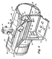
図4において最もよく分かるように、ケーシング20の部分24はまた、端子クロージャ14に接合してその上に端子クロージャ14を支持するための支持面50を含む。支持面50は、ケーシング20の内側および外側で略平坦である。支持面50には少なくとも1つの開口部52が形成され、それを通って、光ファイバまたは銅線などの通信回線がスプライスクロージャ12から端子クロージャ14へ通過することができる。支持面50は開放シーム21の下にケーシング20の側面に設置されるように位置決めされ、その上に支持される端子クロージャ14が端子10の側面または前面から容易にアクセス可能になっている。部分24は任意に、端子クロージャ14に入る引込線(図示せず)を支持する複数の引込線歪み緩和ブラケット60をその外面に支持する。
As best seen in FIG. 4, the
端子クロージャ14は、スプライスクロージャ12および端子クロージャ14を単一構造に形成するために、任意の適切な手段によって支持面50でケーシング20に接合される。スプライスクロージャ12および端子クロージャ14が最初は、個別のユニットとして形成される場合には、スプライスクロージャ12および端子クロージャ14を単一構造に形成するための適切な手段としては、たとえば、ポップリベット、小ねじ、ボルト、熱溶接、音波溶接などを用いて、スプライスクロージャ12および端子クロージャ14を接合することが挙げられる。スプライスクロージャ12および端子クロージャ14は別法として、クロージャ12、14を個別のユニットとして最初に形成するのではなく、単一構造として共に成形することによって、単一構造を形成するように接合されてもよい。
The
支持面50は、端子10が支持ケーブル(図示せず)から懸架されるときに、ケーシング20の側面に端子クロージャ14を配置するように位置決めされる。端子クロージャ14は、上壁70、下壁72、端壁74、75、後壁76および蓋78を備える。蓋78は、端子クロージャ14の上壁70に蝶着され、圧縮成形される蝶番80によって蝶着されることが好ましい。すなわち、蝶番80は、端子クロージャ14の上壁70および蓋78と一体である。端子クロージャ14は、ポリエチレンなどの適切なポリマー材料から成形されてもよい。このように、蝶番80は、成形されるときに、端子クロージャ14の壁および蓋と容易に一体形成することができる。端子クロージャ14は、吹込成形、射出成形などの任意の従来の成形技術によって形成されてもよい。
The
図4において最もよく分かるように、蓋78は、その外面に蝶番80に隣接して移動止め81を備え、ケーシング20の外壁は、凹部64を画定する凹状部分を備えた突出部62を備える。移動止め81はケーシング20における凹部64と協働し、蓋78がたとえば、端子クロージャ14の中身に作業するサービス技術者によって十分に持ち上げられるときに、開放して持ち上げられた位置に蓋78を維持する。スプライスクロージャ12および端子クロージャ14を形成するポリマー材料の可撓性は、移動止め81を凹部64に入れることによって持ち上げた開放位置に蓋78を固定することができるほど十分である。蓋78および下壁72は、協働するラッチ82、84を有し、蓋78を閉鎖位置に保持する。
As best seen in FIG. 4, the
使用中、端子10は、1ヶ所以上の位置に信号を分散するためにケーブルが「スプライス接続される」点で通信ケーブルを包囲するために用いられる。「スプライス接続される」という表現は、本願明細書で用いられるとき、通信ケーブルにおける信号が1ヶ所以上の位置に分散するために、ケーブルから経路指定される任意の通路を含むことを理解し、意図することに留意されたい。実際には、通信ケーブルをスプライス接続、分割、タップ接続、結合してもよい。たとえば、通信ケーブルは、複数のデータ線を含みうる。所定の点で、ケーブルはスプライス接続され、複数のデータ線のうちの1つ以上からの信号が主ケーブルから経路指定される。これは、一例として、電話ネットワークで生じると考えられ、1次または「中継線」通信ケーブルが領域を通って経路指定され、周期的に、1つ以上の個別のデータ線がネットワークの「分岐」に分散される。ネットワークが個別の家庭、会社、オフィスなどに達するまで、分岐をさらに分散してもよい。分散線は、引込線または配電線と呼ばれることが多い。 In use, terminal 10 is used to surround the communication cable in that the cable is “spliced” to distribute the signal to one or more locations. The expression “spliced” as used herein is understood to include any path routed from the cable to distribute the signal in the communication cable to one or more locations; Note that it is intended. In practice, communication cables may be spliced, split, tapped, or coupled. For example, a communication cable can include multiple data lines. At a given point, the cables are spliced and signals from one or more of the plurality of data lines are routed from the main cable. This is considered to occur, for example, in a telephone network, where a primary or “relay” communication cable is routed through an area, and periodically one or more individual data lines are “branched” in the network. To be distributed. Branches may be further distributed until the network reaches individual homes, businesses, offices, etc. Dispersion lines are often referred to as service lines or distribution lines.
光ファイバ通信ケーブルの例において、ケーブルは複数のバッファチューブを含んでもよく、各バッファチューブは複数の個別の光ファイバを含む。ケーブルに沿った種々の点で、光ファイバから1つ以上のバッファチューブに分岐することが望ましい場合があるが、ケーブルの光ファイバのすべてに当てはまる必要はない。バッファチューブの個別の光ファイバは、対応する引込線に直にスプライス接続されてもよく、または単独のファイバの信号が2つ以上の引込線に分散されるように、スプリッタまたはカプラなどを用いて個別の光ファイバを分割してもよい。現時点では、端子10は主に光ファイバ通信ケーブルと共に用いられるものとして本願明細書に記載されているが、端子10は一般に導電性(すなわち、銅)ケーブルをはじめとする通信ケーブルと共に用いられてもよく、端子10は光ファイバケーブルと共に用いることに限定されるわけではないことに留意されたい。通信ケーブルの各タイプは、対応する素子を有し、ケーブルから引込線に信号を経路指定するための方法を有し、それらの素子および方法のそれぞれは、「スプライス」および「スプライス接続」に関連して含められることを理解し、意図されたい。
In the example of a fiber optic communication cable, the cable may include a plurality of buffer tubes, each buffer tube including a plurality of individual optical fibers. Although it may be desirable to branch from the optical fiber to one or more buffer tubes at various points along the cable, it need not be true for all of the optical fibers in the cable. The individual optical fibers in the buffer tube may be spliced directly to the corresponding lead wires, or separate, such as with a splitter or coupler, so that the signal of a single fiber is distributed over two or more lead wires. The optical fiber may be divided. At this time,
図2において最もよく分かるように、フレーム90は、スプライスクロージャ12の中に取付けられる。フレーム90は、たとえば、ポップリベット、小ねじ、ボルトなどの適切な固締素子を用いて、スプライスエンクロージャ12の中に固定される。あるいは、スプライスクロージャ12の中にフレーム90を固定するために、他の固締素子を必要としないように、フレーム90は、スプライスクロージャ12によってオーバモールドされてもよい。取付け用ブラケット92は、通信ケーブル116(図6に示す)に取付けるために、スプライスクロージャ12の第1の端部30および第2の端部32に隣接して設けられる。一実施形態において、取付け用ブラケット92は、通信ケーブルの強度部材に取付けるための歪み緩和特徴部94を備える。図2および図6に示される実施形態において、歪み緩和特徴部94は、たとえば、通信ケーブルおよびその強度部材を固定するケーブルクランプまたはケーブルタイを嵌合するために、凹部領域96を含む。
As best seen in FIG. 2, the
上述したように、多くの用途では、通信ケーブルにおける複数のデータ線の一部のみが、スプライス接続されることになる。使い勝手の良さから、端子10を通過するだけのデータ線からスプライス接続されることになっているデータ線を分離することが望ましい。フレーム90は、スプライスクロージャ12の中で通信ケーブルのスプライス接続されたデータ線から通信ケーブルの非スプライス接続データ線を保持するための保持部材100を含む。特に、保持部材100は、フレーム90の第1の側面102に隣接するスプライス接続線および第1の側面102に対向するフレーム90の第2の側面104に隣接する非スプライス接続線を維持する。
As described above, in many applications, only a part of the plurality of data lines in the communication cable is spliced. For ease of use, it is desirable to separate the data line that is to be spliced from the data line that only passes through the terminal 10. The
非スプライス接続線からスプライス接続線を分離するために、フレーム90は、スプライス接続線をフレーム90の第1の側面102に向け、非スプライス接続線を第2の側面104に向けるための分離ポート110を含む。光ファイバケーブルと合わせた端子10の例示的な使用において、その中にスプライス接続またはタップ接続される光ファイバを有する1つ以上のバッファチューブは、分離ポート110を通してフレーム90の第1の側面102に経路指定されるのに対し、ケーブルの他のバッファチューブは、フレーム90の第2の側面104に隣接したままである。開口部114が、分離ポート110に隣接するフレーム90に設けられ、分離ポート110によって経路指定されるデータ線をケーブルクランプ、ケーブルタイなどによってフレーム90に固定してもよい。
In order to separate the splice connection line from the non-splice connection line, the
図6において、通信ケーブル116は、ケーブルクランプ118を用いてフレーム90に固定される(スプライスクロージャ12は、図示せず)。フレーム90は、その第1の側面102に、通信ケーブル116の分離されたデータ線123に接続するための通信回線122を有するスプライストレイ120を備えている。通信回線122は、たとえば、予め終端されたピグテールをスプライストレイ120で通信ケーブル116の分離されたデータ線123とスプライス接続するために、第1の端部124に用意してもよく、端子クロージャ14における開口部またはカットアウト182を通して1本以上の引込線(図示せず)との接続のために第2の端部126に用意してもよい。任意の適切な態様では、スプライストレイ120をフレーム90に固定してもよい。収納領域150において実際のスプライス接続を保持することに加えて、スプライストレイ120はまた、余分な長さの通信回線122またはデータ線123を保持するための収納領域152、154を提供することが好都合である。別の実施形態において、通信回線122を省略してもよく、分離されたデータ線123を終端して、端子クロージャ14における1本以上の引込線と直接接続してもよい。
In FIG. 6, the
ケーブル116の1本以上の分離されたデータ線123がスプライス接続された後で、通信回線122(あるいはデータ線123)は、1つ以上の開口部52によって端子クロージャ14の中に経路指定される(図2および図3)。説明を分かりやすくするために、端子クロージャ14の中の通信回線122およびデータ線123は一般に、データ線123と呼ぶが、通信回線122またはデータ線123のいずれかまたはその両方が端子クロージャ14に存在してもよいことを理解されたい。
After one or more
端子クロージャ14の中で、データ線123は、端子クロージャ14の外側に延在する1本以上の引込線(図示せず)との接続を確立するための接続素子140を備える。光ファイバケーブルと合わせた端子10の例示的な使用において、接続素子140は、ケーブル(通信回線122またはデータ線123のいずれか)の個別の光ファイバに終端されてもよい。当業者は、接続素子140が、スプライス、コネクタまたは他のタイプの接続素子のいずれであれ、種々の適切な素子のいずれであってもよいことを認識するであろう。さらに、接続素子140は、カプラ、レセプタクルおよびスプライス、コネクタまたは他のタイプの接続素子と共に用いられる他の位置合わせ素子と組み合わせて用いてもよい。たとえば、接続素子140は、SC型コネクタ、DC型コネクタ、SC−DC型コネクタ、ST型コネクタ、FC型コネクタ、LC型コネクタ、MTP型コネクタまたはMTRJ型コネクタなどのコネクタであってもよく、二、三の例を挙げると、たとえば、プラスコンタクト(PC)タイプまたは角度付き研磨コネクタ(APC)タイプのいずれのコネクタであってもよい。接続素子140は、米国ミネソタ州セントポール(Saint Paul,MN,U.S.A.)のスリーエム・カンパニー(3M Company)から入手可能な「ファイバロック(Fibrlok)TM」スプライスなどのスプライスであってもよい。さらに、接続素子140は、米国ノースカロライナ州ヒッコリー(Hickory,NC,U.S.A.)のコーニング・ケーブル・システムズ(Corning Cable Systems)から入手可能な「オプティタップ(OptiTap)TM」光ファイバレセプタクルなどの結合素子と組み合わせて用いてもよい。一部の実施形態において、2つ以上のタイプの接続素子140は、単独の端子クロージャ14の中に用いられてもよい。
Within the
所望であれば、端子クロージャ14の主要な開口部(すなわち、蓋78)を開放することによって、端子クロージャ14における接続素子140のすべてに同時にアクセスしてもよい。たとえば、端子10の取付け中およびケーブル116におけるデータ線123の最初のスプライス接続中に、接続素子140のすべてに同時にアクセスすることが所望であってもよく、または必要であってもよい。しかし、上述したように、光ファイバおよびそれらの接続素子は、物理的な運搬および埃、湿気などのデブリの存在の影響を受けやすい。したがって、端子クロージャ14が開放されるときに接続素子140およびファイバのすべてが露出されると、端子クロージャ14への再挿入中のファイバまたは接続素子140の損傷の可能性が増大する。したがって、端子エンクロージャ14においてすべての光ファイバおよび接続素子140を露出させることなく、端子エンクロージャ14における1つまたは制限された数の光ファイバ接続素子140にアクセスすることができれば、きわめて望ましい。
If desired, all of the
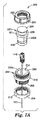
図7Aおよび図7Bを参照すると、端子クロージャ14の外部から接続素子140を端子クロージャ14からの引き出しまたは取り出しを可能にするためのアダプタ200が示されている。アダプタ200は、第1の端部206から第2の端部208まで中を延在する通路またはポート204を有する本体部分202を含む。ポート204は、その中に接続素子140に収容し、接続素子140をポート204の長さを自在に通過させることができるようなサイズである。フランジ210は、本体部分202から横方向の外側に延在する。本体部分202の第1の端部206およびフランジ210は、第1の端部206が端子ハウジング14の壁72にあるカットアウト182(図4)を通過するのに対し、フランジ210がカットアウト182を通過するのを阻止するような大きさである。端子クロージャ14(図示せず)の内側に位置しているリテーナナット212は、第1の端部206と嵌合し、カットアウト182の内部で本体部分202を固定する。図8Aおよび図8Bに示された他の実施形態において、本体部分202は、端子クロージャ14の壁72と一体に形成され、フランジ210およびリテーナナット212が不必要になっている。
Referring to FIGS. 7A and 7B, an
アダプタ200は、接続素子140を嵌合するために構成された接続素子レセプタクル220をさらに含む。レセプタクル220は、さまざまな接続素子タイプを嵌合するように構成されてもよく、または別法として1つの接続素子タイプのみを嵌合するように構成されてもよい。接続素子レセプタクル220は、レセプタクル220がポート204を完全に通過しないようにし、端子クロージャ14の外部からのみレセプタクルをポート204から取り外すことができるようにするためのフランジ221を含む。レセプタクル220は、本体部分202の第2の端部208に対してフランジ221を捕捉するリテーナナット222によって、ポート204の中で取外し可能に保持される。示された実施形態において、リテーナナット212、222はそれぞれ、第1および第2の端部206、208と螺合可能に嵌合され、その周縁面にリッジ、凹部または平坦部などの把持部分224を含み、工具または手によってリテーナナット212、222の回転を容易にする。しかし、スナップ嵌め、リテーナリング、リテーナピンなどの他の嵌合手段もまた用いることができる。
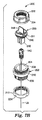
図7Aおよび図8Aにおいて、接続素子レセプタクル220は、引込線などのハウジングの外側に延在する通信回線を終端する嵌合接続素子(図示せず)と接続素子140の接続を容易にするためのカプラ230である。ポート204およびカプラ230は、嵌合平坦部232a、232bなどの楔止手段を任意に備え、ポート204の中でカプラ230の適切な向きを確保するか、または所定のタイプのカプラ230のみをポート204に挿入することが可能となるようになっている。接続素子140が嵌合接続素子に直に接続されない場合には、嵌合接続素子が形成されるまで、接続素子140は、カプラ230に着座されてもよい。嵌合コネクタが存在しない場合には、キャップ234が、カプラ230を閉鎖するように設けられ、それによって、アダプタ200および端子ハウジング14の中への湿気、埃および他の汚染物質の侵入を防止する。キャップ234は、周縁リッジ236または他の把持手段を備えて、ユーザがポート204からカプラ230および(着座される接続素子140)を取り出しするのを助けることが好ましい。
7A and 8A, the
図7Bおよび図8Bにおいて、接続素子レセプタクル220は、アダプタ200および端子ハウジング14の中への湿気、埃および他の汚染物質の侵入を防止するためのシーリング部材240である。シーリング部材240は、そのように所望であれば、接続素子140を着座するためのダミーレセプタクル242を備える。タブ246または他の把持手段は、ユーザがポート204からシーリング部材240(および着座した接続素子140)を取り出しするのを助けるために設けられる。シーリング部材240は、熱可塑性エラストマ(TPE)タイプまたは熱可塑性加硫物(TPV)タイプの材料をはじめとするゴムまたはポリマー材料などの任意の適切な可撓性かつ弾性の材料から構成される。シーリング部材240は、紫外安定性、化学的不活性、可撓性、耐引裂性および適度に耐圧縮永久歪み性である材料から構成されることが好ましい。別法の実施形態において、アダプタ本体部分202が端子ハウジング14と一体に形成されない場合には、シーリング部材240は、カットアウト182に直に適合し、シーリング部材材料の弾性的な性質によって、その中に固定されたままであるような大きさであってもよい。
7B and 8B, the connecting
接続素子レセプタクル220に着座される接続素子140がハウジングの外側で嵌合接続素子(図示せず)に接続されることになっている場合には、接続を完了するために、端子ハウジング14の蓋78(すなわち主要な開口部)を開放することは必要ではない。レセプタクル220がカプラ230である場合には、キャップ234は単に取り外されるだけであり、接続を完了するために嵌合接続素子がカプラ230の中に挿入される。接続を完了する前に接続素子140を洗浄または他の方法で前処理をすることが必要であるか、または望ましい場合には、リテーナナット222が取り外され、カプラ230が着座した接続素子140と共にポート204から取り出しされる。この場合も同様に、端子ハウジング14の蓋78を開放する必要はない。着座した接続素子140は、洗浄または他の前処理のために、カプラ230から取り外され、次に、前処理された接続素子がカプラ230に再挿入される。カプラ230は、この場合も同様にポート204の中に挿入され、リテーナナット222は、カプラ230を固定するために再取付けされ、次に、嵌合接続素子の挿入を可能にするために、キャップ234が取り外される。
If the
接続素子140がシーリング部材240に着座され、ハウジングの外側で嵌合接続素子に接続されることになっている場合には、この場合も同様に、接続を完了するために、端子ハウジング14の蓋78を開放する必要はない。最初に、リテーナナット222が取り外され、シーリング部材240が着座した接続素子140と共にポート204から取り出しされる。着座した接続素子140は、洗浄または他の前処理のために、シーリング部材240から取り外される。次に、前処理された接続素子140がカプラ230に挿入され、上述したように、嵌合接続素子への接続が続いて行われる。あるいは、前処理された接続素子140が、何か他の方法(スプライス接続によるなど)で嵌合接続素子に接続され、ポート204を通じて端子クロージャ14への湿気、埃、虫の侵入を防止する適切なシーリング手段を用いて、アダプタ200のポート204に再取付けされてもよい。
If the
アダプタ200の本体部分202は、図7A〜図8Bに示される実施形態以外の実施形態を有してもよい。たとえば、図9において、アダプタ300は、第1の端部306から第2の端部308まで中を延在する通路またはポート304を有する本体部分302を備える。ポート304は、その中に接続素子140に収容し、接続素子140をポート304の長さを自在に通過させることができるようなサイズである。本体部分302の第1の端部306は、スナップ嵌め態様で通信エンクロージャ312に開口部310を嵌合するように形成される。弾性Oリング314は、本体部分302の第1の端部306とエンクロージャ312との間の湿気シールを提供する。第1の端部306は任意に、データ線123を固定することができる歪み緩和特徴部316を備える。アダプタ300は、図7A〜図8Bに関して上述したように、カプラ230(図示せず)またはシーリング部材240およびリテーナナット222と共に用いられる。
The
図10Aおよび図10Bは、アダプタ200に実装されるカットアウト182のすべてを有する端子クロージャ14の部分を示している。アダプタ200の部分は、カプラ230で充填され、アダプタ200の他の部分は、シーリング部材240で充填される。図10Bにおいて最もよく分かるように、カプラ230およびシーリング部材240のそれぞれを用いて、端子クロージャ14の壁に隣接して接続素子140を着座してもよく、接続素子140がその主要な開口部を介してクロージャ14に入ることなく、壁を通って取り出しされるようになっていてもよい。接続素子140はすべて、単独の接続素子タイプであってもよく、または別法として2つ以上の異なる接続素子タイプを含んでもよい。接続素子140が異なるタイプである場合には、カプラおよびシーリング部材は、異なる接続素子タイプの1つのみに嵌合するように構成されてもよい。
FIGS. 10A and 10B show a portion of the
端子が個別のスプライスおよび端子クロージャを含む場合には、本発明のエンクロージャは、複数の光ファイバを有する光ファイバケーブルと共に用いるための空中端子に関して本願明細書に記載されている。本発明による他の実施形態において、エンクロージャは、任意の地上または地下のハウジングを備えることができ、光通信ケーブルまたは電気通信ケーブルと共に用いられてもよい。さらに、本発明によるエンクロージャの他の実施形態は、個別のスプライスおよび端子クロージャを有する必要はない。図示されているように、接続素子レセプタクル220は、単独の接続素子140と嵌合する。しかし、接続素子レセプタクル220はまた、2つ以上の接続素子140と嵌合するように構成されてもよく、他の方法で記載した態様で動作し続けてもよい。
Where the terminals include individual splices and terminal closures, the enclosure of the present invention is described herein with respect to aerial terminals for use with fiber optic cables having a plurality of optical fibers. In other embodiments according to the present invention, the enclosure may comprise any above-ground or underground housing and may be used with optical or telecommunications cables. Furthermore, other embodiments of the enclosure according to the present invention need not have separate splices and terminal closures. As shown, the
好ましい実施形態の説明のために、特定の実施形態が本願明細書に図示および記載されているが、種々の代替の実装例または等価な実装例は、本発明の範囲を逸脱することなく、図示および記載された特定の実施形態の代わりに行うことができることを当業者は十分に理解されたい。機械業界、光学業界および光学機械業界の当業者は、多種多様な実施形態において本発明を実装することができることを容易に理解されるであろう。本願明細書は、本願明細書で説明される実施形態の任意の変更または変形を網羅することを意図している。したがって、本発明は、特許請求の範囲およびその等価物によってのみ限定されることを明白に表している。 While specific embodiments have been illustrated and described herein for the purpose of illustrating the preferred embodiments, various alternative or equivalent implementations may be illustrated without departing from the scope of the invention. And those skilled in the art will appreciate that this can be done in place of the specific embodiments described. Those of skill in the mechanical, optical, and optical machine industries will readily appreciate that the present invention can be implemented in a wide variety of embodiments. This document is intended to cover any modifications or variations of the embodiments described herein. Therefore, it is manifestly intended that this invention be limited only by the claims and the equivalents thereof.
Claims (36)
その中に通信ケーブルのスプライス接続された通信回線を保持するためのハウジングと、
複数の接続素子であって、前記複数の接続素子の少なくとも1つは、前記ハウジングの中で前記スプライス接続された通信回線の1つに接続され、前記ハウジングの外側に延在する通信回線を終端する嵌合接続素子に接続するように構成される接続素子と、
前記ハウジングにおける前記複数の接続素子のそれぞれへの同時アクセスを可能にする前記ハウジングにおける主要な入口と、
前記ハウジングの壁に一体に形成され、前記ハウジングの外部から前記ハウジングの前記壁を通って前記複数の接続素子の1つのアクセスおよび取り出しを可能にするように構成されるアダプタと、を備えるエンクロージャ。 An enclosure for a communication cable having a plurality of communication lines,
A housing for holding a communication line spliced to the communication cable therein;
A plurality of connection elements, wherein at least one of the plurality of connection elements is connected to one of the splice-connected communication lines in the housing and terminates a communication line extending outside the housing A connecting element configured to connect to the mating connecting element to
A main inlet in the housing that allows simultaneous access to each of the plurality of connecting elements in the housing;
An enclosure formed integrally with the wall of the housing and configured to allow access and removal of one of the plurality of connecting elements from the exterior of the housing through the wall of the housing.
通信回線におけるスプライスを保持するためのスプライス区画と、
前記スプライス区画に保持されるスプライスから離れて通信回線接続素子を保持するための端子区画と、
前記端子区画に隣接する前記エンクロージャの壁を通って延在する少なくとも1つのポートと、を備え、前記少なくとも1つのポートは、接続素子を収容し、前記エンクロージャの外側から前記壁を通って前記接続素子の取り出しを可能にするように構成されるエンクロージャ。 An enclosure for a communication line,
A splice compartment to hold the splice in the communication line;
A terminal section for holding the communication line connection element away from the splice held in the splice section;
At least one port extending through the wall of the enclosure adjacent to the terminal compartment, wherein the at least one port accommodates a connection element and the connection through the wall from the outside of the enclosure An enclosure configured to allow device removal.
通信ケーブルのスプライス接続された通信回線を保持するためのスプライスクロージャと、
前記スプライスクロージャに接合される端子クロージャであって、前記スプライスクロージャにおける対応する前記通信回線に接続される複数の接続素子を保持するように構成される端子クロージャと、
前記端子クロージャの外壁を通って延在する少なくとも1つの閉鎖可能なポートと、を備え、前記少なくとも1つの閉鎖可能なポートは、前記端子クロージャの外部から前記ポートを通って前記端子クロージャから接続素子を引き出すことを可能にするように構成される通信ケーブル用の端子。 A terminal for a communication cable having a plurality of communication lines,
A splice closure for holding a spliced communication line of communication cables;
A terminal closure joined to the splice closure, the terminal closure configured to hold a plurality of connecting elements connected to the corresponding communication line in the splice closure;
At least one closable port extending through an outer wall of the terminal closure, the at least one closable port from the terminal closure through the port from the outside of the terminal closure A terminal for a communication cable that is configured to allow drawing out.
Applications Claiming Priority (2)
| Application Number | Priority Date | Filing Date | Title |
|---|---|---|---|
| US10/916,332 US7256349B2 (en) | 2004-08-11 | 2004-08-11 | Telecommunications cable enclosure |
| PCT/US2005/022760 WO2006023072A1 (en) | 2004-08-11 | 2005-06-23 | Telecommunications cable enclosure |
Publications (2)
| Publication Number | Publication Date |
|---|---|
| JP2008510179A true JP2008510179A (en) | 2008-04-03 |
| JP2008510179A5 JP2008510179A5 (en) | 2008-08-07 |
Family
ID=34973095
Family Applications (1)
| Application Number | Title | Priority Date | Filing Date |
|---|---|---|---|
| JP2007525612A Pending JP2008510179A (en) | 2004-08-11 | 2005-06-23 | Communication cable enclosure |
Country Status (8)
| Country | Link |
|---|---|
| US (2) | US7256349B2 (en) |
| EP (1) | EP1787153B1 (en) |
| JP (1) | JP2008510179A (en) |
| KR (1) | KR20070044449A (en) |
| AR (1) | AR050834A1 (en) |
| ES (1) | ES2797477T3 (en) |
| TW (1) | TW200628867A (en) |
| WO (1) | WO2006023072A1 (en) |
Families Citing this family (15)
| Publication number | Priority date | Publication date | Assignee | Title |
|---|---|---|---|---|
| US7333709B2 (en) * | 2004-09-24 | 2008-02-19 | 3M Innovative Properties Company | Splice holder device |
| US7469091B2 (en) * | 2004-12-22 | 2008-12-23 | Tyco Electronics Corporation | Optical fiber termination apparatus and methods for using the same |
| US7715678B2 (en) * | 2006-02-10 | 2010-05-11 | 3M Innovative Properties Company | Optical fiber loopback test system and method |
| US8023794B2 (en) * | 2009-08-10 | 2011-09-20 | The Boeing Company | Apparatus and method for establishing an optical path spanning a discontinuity in an optical channel |
| US8472773B2 (en) | 2010-08-06 | 2013-06-25 | Corning Cable Systems Llc | Fiber optic connector holder |
| AU2012225855B2 (en) * | 2011-03-07 | 2015-10-22 | Tyco Electronics Corporation | Cable strain relief clamping devices and methods for using the same |
| US9198308B2 (en) | 2013-03-14 | 2015-11-24 | Hubbell Incorporated | Metro cell aggregator enclosure |
| WO2015066185A1 (en) * | 2013-10-29 | 2015-05-07 | 3M Innovative Properties Company | Fiber optic splice closure |
| AU2015236259B2 (en) | 2014-03-24 | 2019-01-24 | Commscope Technologies Llc | Plate for cable connector attachments |
| ES2894250T3 (en) * | 2014-04-14 | 2022-02-14 | Commscope Connectivity Belgica Bvba | Fiber Optic Enclosure with Cable Management Drawer |
| US20160025260A1 (en) * | 2014-07-24 | 2016-01-28 | Emerson Network Power, Energy Systems, North America, Inc. | Hinged pedestal bases |
| WO2016109425A1 (en) * | 2014-12-29 | 2016-07-07 | Commscope Technologies Llc | Telecommunications enclosure with cable seal |
| MX2017010350A (en) | 2015-02-13 | 2018-01-23 | 3M Innovative Properties Co | Telecommunication enclosure having integrated termination tools. |
| US10359590B2 (en) | 2016-04-04 | 2019-07-23 | Opterna Technology Limited | Fiber optic cable deployment assemblies, systems, and methods |
| WO2019079425A1 (en) * | 2017-10-17 | 2019-04-25 | Corning Research & Development Corporation | Enclosure for splicing of optical fibers |
Citations (9)
| Publication number | Priority date | Publication date | Assignee | Title |
|---|---|---|---|---|
| US5042901A (en) * | 1990-07-31 | 1991-08-27 | Siecor Corporation | Preconnectorized optical splice closure |
| JPH05113509A (en) * | 1991-10-23 | 1993-05-07 | Sumitomo Electric Ind Ltd | Optical pull-down connecting box and pull-down method |
| JPH05215933A (en) * | 1992-02-05 | 1993-08-27 | Sumitomo Electric Ind Ltd | Optical pull-down connection box |
| US5247135A (en) * | 1992-02-07 | 1993-09-21 | Minnesota Mining And Manufacturing Company | Aerial terminal |
| US5778122A (en) * | 1996-12-24 | 1998-07-07 | Siecor Corporation | Fiber optic cable assembly for interconnecting optical fibers within a receptacle mounted within the wall of an enclosure |
| JPH11109178A (en) * | 1997-10-02 | 1999-04-23 | Oki Electric Ind Co Ltd | Optical fiber connector |
| JP2000241630A (en) * | 1999-02-19 | 2000-09-08 | Fujikura Ltd | Optical module |
| JP2003177254A (en) * | 2001-12-10 | 2003-06-27 | Furukawa Electric Co Ltd:The | Closure |
| WO2004061511A2 (en) * | 2002-12-30 | 2004-07-22 | 3M Innovative Properties Company | Unitary splice and drop wire closure |
Family Cites Families (25)
| Publication number | Priority date | Publication date | Assignee | Title |
|---|---|---|---|---|
| US3138657A (en) * | 1962-07-27 | 1964-06-23 | Fargo Mfg Co Inc | Splice insulating system |
| US3711815A (en) * | 1971-06-24 | 1973-01-16 | Gen Connector | Tight angle multi-contact electrical connector |
| GB8815894D0 (en) | 1988-07-04 | 1988-08-10 | Bicc Plc | Connecting device |
| US4958903A (en) * | 1988-12-09 | 1990-09-25 | At&T Bell Laboratories | Splice closure |
| GB8911889D0 (en) | 1989-05-23 | 1989-07-12 | Stockman Anthony J | A device for use in connecting optical fibre cables |
| CH683646A5 (en) | 1992-05-20 | 1994-04-15 | Diamond Sa | Plug connector for optical fibres - has socket releasably fixed in holder which can be drawn out of housing wall to allow detachment of connector |
| US5521998A (en) * | 1994-12-13 | 1996-05-28 | United Technologies Corporation | Strain relief backshell for fiber optic transmission lines |
| EP0805536A1 (en) | 1996-05-01 | 1997-11-05 | Bowthorpe Plc | Cable enclosure |
| US5745633A (en) * | 1996-12-24 | 1998-04-28 | Siecor Corporation | Fiber optic cable assembly for securing a fiber optic cable within an input port of a splice closure |
| US6067395A (en) * | 1997-05-15 | 2000-05-23 | Ocean Design, Inc. | Underwater bulkhead feedthrough assembly |
| US5923802A (en) * | 1997-06-06 | 1999-07-13 | Siecor Corporation | Flexible connector assembly having slack storage |
| US6175483B1 (en) * | 1998-01-07 | 2001-01-16 | Maspro Denkoh Company, Ltd. | Multi-tap distribution apparatus |
| FR2782172B1 (en) * | 1998-08-04 | 2001-11-30 | Pouyet Sa | OPTICAL FIBER CABLE INPUT DEVICE |
| FR2782171B1 (en) * | 1998-08-04 | 2001-11-30 | Pouyet Sa | FIBER OPTIC CABLES CONNECTION DEVICE |
| GB9909114D0 (en) | 1999-04-21 | 1999-06-16 | Raychem Sa Nv | Optical fibre organiser |
| US6385381B1 (en) * | 1999-09-21 | 2002-05-07 | Lucent Technologies Inc. | Fiber optic interconnection combination closure |
| US6648520B2 (en) * | 2001-09-28 | 2003-11-18 | Corning Cable Systems Llc | Fiber optic plug |
| US6467971B1 (en) | 2000-10-10 | 2002-10-22 | Neptec Optical Solutions, Inc. | Removable optical adapter and receptor |
| GB2368139A (en) | 2000-10-17 | 2002-04-24 | Spirent Plc | Optic fibre splice storage tray stack |
| GB0111793D0 (en) | 2001-05-15 | 2001-07-04 | Spirent Plc | Cable jointing enclosure |
| WO2003019243A2 (en) * | 2001-05-21 | 2003-03-06 | Wave7 Optics, Inc. | Cable splice enclosure and components |
| US6579014B2 (en) * | 2001-09-28 | 2003-06-17 | Corning Cable Systems Llc | Fiber optic receptacle |
| US6909833B2 (en) * | 2002-03-15 | 2005-06-21 | Fiber Optic Network Solutions, Inc. | Optical fiber enclosure system using integrated optical connector and coupler assembly |
| US6721484B1 (en) * | 2002-09-27 | 2004-04-13 | Corning Cable Systems Llc | Fiber optic network interface device |
| BR0314658A (en) | 2002-10-11 | 2005-08-02 | 3M Innovative Properties Co | Fiber Management System |
-
2004
- 2004-08-11 US US10/916,332 patent/US7256349B2/en not_active Expired - Lifetime
-
2005
- 2005-06-23 EP EP05764354.6A patent/EP1787153B1/en active Active
- 2005-06-23 ES ES05764354T patent/ES2797477T3/en active Active
- 2005-06-23 JP JP2007525612A patent/JP2008510179A/en active Pending
- 2005-06-23 WO PCT/US2005/022760 patent/WO2006023072A1/en active Application Filing
- 2005-06-23 KR KR1020077003183A patent/KR20070044449A/en not_active Application Discontinuation
- 2005-07-07 TW TW094123046A patent/TW200628867A/en unknown
- 2005-08-08 AR ARP050103303A patent/AR050834A1/en unknown
-
2007
- 2007-07-17 US US11/778,967 patent/US7598457B2/en not_active Expired - Lifetime
Patent Citations (10)
| Publication number | Priority date | Publication date | Assignee | Title |
|---|---|---|---|---|
| US5042901A (en) * | 1990-07-31 | 1991-08-27 | Siecor Corporation | Preconnectorized optical splice closure |
| JPH05113509A (en) * | 1991-10-23 | 1993-05-07 | Sumitomo Electric Ind Ltd | Optical pull-down connecting box and pull-down method |
| JPH05215933A (en) * | 1992-02-05 | 1993-08-27 | Sumitomo Electric Ind Ltd | Optical pull-down connection box |
| US5247135A (en) * | 1992-02-07 | 1993-09-21 | Minnesota Mining And Manufacturing Company | Aerial terminal |
| US5778122A (en) * | 1996-12-24 | 1998-07-07 | Siecor Corporation | Fiber optic cable assembly for interconnecting optical fibers within a receptacle mounted within the wall of an enclosure |
| JPH11109178A (en) * | 1997-10-02 | 1999-04-23 | Oki Electric Ind Co Ltd | Optical fiber connector |
| JP2000241630A (en) * | 1999-02-19 | 2000-09-08 | Fujikura Ltd | Optical module |
| JP2003177254A (en) * | 2001-12-10 | 2003-06-27 | Furukawa Electric Co Ltd:The | Closure |
| WO2004061511A2 (en) * | 2002-12-30 | 2004-07-22 | 3M Innovative Properties Company | Unitary splice and drop wire closure |
| JP2006512614A (en) * | 2002-12-30 | 2006-04-13 | スリーエム イノベイティブ プロパティズ カンパニー | Long-distance communication terminal |
Also Published As
| Publication number | Publication date |
|---|---|
| WO2006023072A1 (en) | 2006-03-02 |
| US7256349B2 (en) | 2007-08-14 |
| US20070256848A1 (en) | 2007-11-08 |
| EP1787153B1 (en) | 2020-03-25 |
| ES2797477T3 (en) | 2020-12-02 |
| TW200628867A (en) | 2006-08-16 |
| EP1787153A1 (en) | 2007-05-23 |
| US7598457B2 (en) | 2009-10-06 |
| KR20070044449A (en) | 2007-04-27 |
| US20060034578A1 (en) | 2006-02-16 |
| AR050834A1 (en) | 2006-11-29 |
Similar Documents
| Publication | Publication Date | Title |
|---|---|---|
| JP2008510179A (en) | Communication cable enclosure | |
| US8071879B2 (en) | Telecommunications cable enclosure | |
| US20210041652A1 (en) | Fiber optic closure | |
| US6721484B1 (en) | Fiber optic network interface device | |
| US8879883B2 (en) | Optical fiber cable inlet device and telecommunications enclosure system | |
| JP2009506749A (en) | Communication line and splice enclosure | |
| US8290329B2 (en) | Fiber access terminal including moisture barrier plate | |
| US5790739A (en) | Optical fiber interconnect and canister closure assembly | |
| US7715678B2 (en) | Optical fiber loopback test system and method | |
| CA2792885C (en) | High fiber count package inner module |
Legal Events
| Date | Code | Title | Description |
|---|---|---|---|
| A521 | Request for written amendment filed |
Free format text: JAPANESE INTERMEDIATE CODE: A523 Effective date: 20080620 |
|
| A621 | Written request for application examination |
Free format text: JAPANESE INTERMEDIATE CODE: A621 Effective date: 20080620 |
|
| RD04 | Notification of resignation of power of attorney |
Free format text: JAPANESE INTERMEDIATE CODE: A7424 Effective date: 20091228 |
|
| A977 | Report on retrieval |
Free format text: JAPANESE INTERMEDIATE CODE: A971007 Effective date: 20110124 |
|
| A131 | Notification of reasons for refusal |
Free format text: JAPANESE INTERMEDIATE CODE: A131 Effective date: 20110201 |
|
| A02 | Decision of refusal |
Free format text: JAPANESE INTERMEDIATE CODE: A02 Effective date: 20110705 |