JP2008509647A - Main components for electrical machines - Google Patents
Main components for electrical machines Download PDFInfo
- Publication number
- JP2008509647A JP2008509647A JP2007525273A JP2007525273A JP2008509647A JP 2008509647 A JP2008509647 A JP 2008509647A JP 2007525273 A JP2007525273 A JP 2007525273A JP 2007525273 A JP2007525273 A JP 2007525273A JP 2008509647 A JP2008509647 A JP 2008509647A
- Authority
- JP
- Japan
- Prior art keywords
- module
- modules
- tooth
- magnetic path
- main component
- Prior art date
- Legal status (The legal status is an assumption and is not a legal conclusion. Google has not performed a legal analysis and makes no representation as to the accuracy of the status listed.)
- Pending
Links
Images


Classifications
-
- H—ELECTRICITY
- H02—GENERATION; CONVERSION OR DISTRIBUTION OF ELECTRIC POWER
- H02K—DYNAMO-ELECTRIC MACHINES
- H02K1/00—Details of the magnetic circuit
- H02K1/06—Details of the magnetic circuit characterised by the shape, form or construction
- H02K1/12—Stationary parts of the magnetic circuit
- H02K1/14—Stator cores with salient poles
- H02K1/146—Stator cores with salient poles consisting of a generally annular yoke with salient poles
- H02K1/148—Sectional cores
-
- H—ELECTRICITY
- H02—GENERATION; CONVERSION OR DISTRIBUTION OF ELECTRIC POWER
- H02K—DYNAMO-ELECTRIC MACHINES
- H02K1/00—Details of the magnetic circuit
- H02K1/06—Details of the magnetic circuit characterised by the shape, form or construction
- H02K1/22—Rotating parts of the magnetic circuit
- H02K1/24—Rotor cores with salient poles ; Variable reluctance rotors
-
- H—ELECTRICITY
- H02—GENERATION; CONVERSION OR DISTRIBUTION OF ELECTRIC POWER
- H02K—DYNAMO-ELECTRIC MACHINES
- H02K1/00—Details of the magnetic circuit
- H02K1/02—Details of the magnetic circuit characterised by the magnetic material
Abstract
本発明は、電気機械、殊に小型直流モーターのための回転子若しくは固定子として使用される主要構成要素に関し、該主要構成要素は透磁性の本体(11)を備えており、該本体は磁路リング(12)及び該磁路リング(12)に一体に成形されて半径方向に突出する歯部(13)を有しており、該歯部は等角度間隔に分配して設けられている。軸線方向の寸法の大きな主要構成要素を、SMC−材料から要求される高い材料密度でプレス成形するために、SMC−本体(11)は、個別に成形されていてかつ軸線方向で互いに接合される複数のモジュール(14,15)に分割されており、該モジュールのうちの各2つのモジュール(14若しくは15)は同一に形成されていて、モジュールの接合に際して、モジュール軸線によって規定された1つの平面内で互いに180°にわたって反転させられている。個別にプレス成形される各モジュール(14,15)は、所望の密度を得るために大きな寸法比を有しており、複数のモジュール(14,15)のプレス成形のために、2つの成形型しか必要としない。 The present invention relates to a main component used as a rotor or stator for an electric machine, in particular a small DC motor, the main component comprising a permeable body (11), which is a magnetic body. The ring (12) and the magnetic path ring (12) are integrally formed with a tooth portion (13) projecting in the radial direction, and the tooth portions are provided at equiangular intervals. . In order to press the main components with large axial dimensions at the high material density required from the SMC-material, the SMC-body (11) is individually molded and joined together in the axial direction. It is divided into a plurality of modules (14, 15), and each of the two modules (14 or 15) is formed identically, and one plane defined by the module axis when the modules are joined together Are inverted over each other by 180 °. Each module (14, 15) that is individually press-molded has a large dimensional ratio to obtain the desired density, and two molds are used for press-molding a plurality of modules (14, 15). I only need it.
Description
本発明は、電気機械、殊に小型直流電動機若しくは小型直流モーターのための回転子若しくは固定子として使用される請求項1の上位概念に記載の形式の主要構成要素に関する。 The present invention relates to main components of the type defined in the superordinate concept of claim 1 used as a rotor or stator for an electric machine, in particular a small DC motor or a small DC motor.
電気機械の回転子(ローター)若しくは固定子(ステーター)の透磁性の本体(主要構成部分又は主要部)は、次第にSMC−材料(Soft Magnetic Powder Iron Composite)から製造されて、殊に小型直流電動機において、積層式の鉄心本体若しくは薄板セットと取って代わられるようになっており、それというのは前記材料は製造技術的にきわめて容易に製造可能であるからである。磁気特性を有する、つまり透磁性のSMC−材料は、薄板積層セットから成る固定子本体若しくは回転子本体に比べてさらなる利点を有し、つまり鉄損の減少、回転数の高い若しくは磁極数の大きなモーターにおける高い周波数、薄い歯部絶縁の使用により改善される熱特性を達成でき、それというのは歯部は、とがった縁及び鋭角の角隅を生ぜしめないようにプレス成形(圧縮成形)され、かつモーターの設計の自由度は高いからである。SMC−材料は一般的にプレス型(成形型又は金型)を用いて固定子若しくは回転子の所望の形にプレス成形され、次いで例えば500°までの比較的に低い温度で熱処理される。プレス成形に際して、材料の高い密度を達成しなければならず、このような高い密度は鉄では約7.8g/cm3になる。このような密度は、圧縮成形体(プレス成形体)の寸法比(aspect ratio[縦横比])をできるだけ大きくしてある場合に得られる。この場合に、寸法比の限界値は1:15である。寸法比は、プレス方向(縦方向)に対して横方向での圧縮成形体(パリソン又は予備成形物)の横断面の最小寸法とプレス方向での圧縮成形体の長さとの比を意味している。 The magnetically permeable body (main component or main part) of the rotor (rotor) or stator (stator) of an electric machine is gradually manufactured from SMC-material (Soft Magnetic Powder Iron Composite), especially a small DC motor However, it can be replaced with a laminated iron core body or a thin plate set, because the material can be manufactured very easily in terms of manufacturing technology. SMC-materials with magnetic properties, i.e. magnetically permeable, have further advantages over stator or rotor bodies consisting of thin laminated sets, i.e. reduced iron loss, high rotational speed or high number of magnetic poles. The use of high frequency, thin tooth insulation in the motor can achieve improved thermal properties because the teeth are pressed (compressed) to avoid sharp edges and sharp corners. This is because the degree of freedom in motor design is high. The SMC-material is typically pressed into the desired shape of the stator or rotor using a press mold (mold or mold) and then heat treated at a relatively low temperature, for example up to 500 °. During press forming, a high density of the material must be achieved, which is about 7.8 g / cm 3 for iron. Such a density is obtained when the dimension ratio (aspect ratio [aspect ratio]) of the compression molded body (press molded body) is made as large as possible. In this case, the limit value of the dimensional ratio is 1:15. The dimensional ratio means the ratio of the minimum dimension of the cross section of the compression molded body (parison or preform) in the transverse direction to the press direction (longitudinal direction) and the length of the compression molded body in the press direction. Yes.
高い寸法比を得るために、インナーローター型機械のためのSMC−材料製の多極式の公知の固定子(WO 99/50949)においては、外周側に位置する磁路リングは、磁路ヨーク若しくは継鉄とも呼ばれ、固定子歯部の歯部数(突極数)に相当する数の円弧片若しくはリングセグメントを周方向で組み合わせて、つまりつなぎ合わせて形成されている。磁路リングの各磁路円弧片は、1つの固定子歯部を一体に保持して、つまり一体成形された1つの固定子歯部を備えており、固定子歯部は歯頸部及び、該歯頸部の、磁路リングから離れた側の端部を画定する歯足部を有している。歯頸部及び歯足部を有する各磁路円弧片は、SMC−材料から圧縮及び熱処理によって製造されている。歯頸部は軸線方向の端部に丸みを付けられ、若しくは楕円形又は長円形の輪郭を有しており、とがった縁、つまりシャープなエッジを排除して薄い絶縁層を施してあり、該絶縁層上に環状コイルを巻成してある。固定子巻線の各個別の環状コイルは、直接に歯頸部に従来の機械による巻成技術によって巻き付けて形成されている。環状コイルの巻成の後に、個別の円弧片(セグメント片)は周方向で互いに接合され、かつ互いに堅く結合される。 In order to obtain a high dimensional ratio, in the SMC-material known multipole stator (WO 99/50949) for inner rotor type machines, the magnetic path ring located on the outer peripheral side is a magnetic path yoke. Alternatively, it is also called a yoke, and is formed by combining, in other words, connecting together arc pieces or ring segments corresponding to the number of teeth (number of salient poles) of the stator teeth in the circumferential direction. Each magnetic path arc piece of the magnetic path ring integrally holds one stator tooth portion, that is, includes one stator tooth portion integrally formed, and the stator tooth portion includes a tooth neck portion, The tooth neck has a tooth foot that defines an end of the tooth neck on the side away from the magnetic path ring. Each magnetic path arc segment having a tooth neck and a foot is manufactured from SMC-material by compression and heat treatment. The neck is rounded at the axial end, or has an oval or oval profile, and a thin insulating layer is applied to eliminate sharp edges, i.e. sharp edges, An annular coil is wound on the insulating layer. Each individual annular coil of the stator winding is formed by wrapping directly around the tooth neck using conventional mechanical winding techniques. After the winding of the annular coil, the individual arc pieces (segment pieces) are joined together in the circumferential direction and firmly joined together.
インナーローター型機械のためのSMC−材料製の同じく公知の固定子(WO 00/69047)においては、磁路リング(ヨーク)と歯頸部及び歯足部から成る固定子歯部とをそれぞれ別個にSMC−材料から所望の形に成形するようになっている。予め製造した環状コイルを歯頸部に被せ嵌めた後に、固定子歯部は歯頸部の、歯足部とは逆の側の端部でもって磁路リングの凹設部若しくは切欠部内に形状結合的に、つまり形状による束縛を伴って差し込まれて、磁路リングに固定されるようになっている。 In the same known stator made of SMC-material for inner rotor type machines (WO 00/69047), the magnetic path ring (yoke) and the stator tooth part consisting of the tooth neck part and the tooth foot part are separately provided. The SMC-material is formed into a desired shape. After fitting the pre-manufactured annular coil over the tooth neck part, the stator tooth part is shaped in the recessed part or notch part of the magnetic path ring with the end of the tooth neck part opposite to the tooth foot part. It is inserted in a coupled manner, that is, with a shape constraint, and is fixed to the magnetic path ring.
電気機械のための請求項1に記載の特徴と有する本発明に基づく主要構成要素においては、利点として、SMC−材料から成形された個別のモジュールは、一方では軸線方向若しくはプレス方向での大きな寸法比を有し、したがって高い材料密度で製造され、かつ他方では、わずかなモジュール、例えば2つのモジュールの接合によって主要構成要素の軸線方向の大きな寸法(長さ)を可能にしている。これによって、直径が小さくかつ高出力を得るために軸線方向の寸法が大きな電気機械、殊に自動車に使用される小型モーター、例えば座席調節用の直流モーター、窓用駆動部、若しくはガソリン直接噴射装置のためのブラシレスの直流モーター等を経済的に製造することができるようになっている。電気機械の極数若しくは歯部数に左右されることなく、軸線方向の寸法の大きな1つの回転子若しくは1つの固定子にとって、もっぱら2つのプレス型若しくは金型で4つのSMC−構成部分若しくは軟磁性鉄粉体製構成部分だけをプレス成形して、次いでこれを互いに接合するだけである。SMC−構成部分の前述の数は、前述の公知のSMC−固定子において完成した1つの固定子を得るためにプレス成形されて組み立てられるべきSMC−構成部分(SMC−構成エレメント)の数に比べて少ないものである。 In the main component according to the invention with the features of claim 1 for an electric machine, as an advantage, individual modules molded from SMC-materials, on the one hand, have large dimensions in the axial or pressing direction. Ratio and thus manufactured with a high material density, and on the other hand, a small number of modules, for example two modules, allow a large axial dimension (length) of the main components. In this way, small motors used in motors, in particular automobiles, for example small-diameters and large axial dimensions in order to obtain high output, for example direct current motors for seat adjustment, window drives or gasoline direct injection devices. It is possible to economically manufacture brushless direct current motors and the like. Regardless of the number of poles or teeth of an electric machine, for one rotor or one stator with a large axial dimension, there are only four SMC components or soft magnets in two press dies or molds. Only the iron powder components are press molded and then joined together. The aforementioned number of SMC-components is compared to the number of SMC-components (SMC-components) to be pressed and assembled to obtain a single stator completed in the aforementioned known SMC-stator. And few.
従属請求項に記載の手段によって、電気機械の請求項1に記載の主要構成要素若しくは主要構成部品の有利な改善を可能にしている。 By means of the dependent claims, an advantageous improvement of the main component or main component of claim 1 of an electric machine is possible.
本発明の有利な実施態様では、同一の2つのモジュールは外側モジュールとして本体の軸線方向で外側に位置しており、別の同一の2つのモジュールは中間モジュールとして前記外側モジュール間に配置されている。この場合に外側モジュールは、両方の中間モジュールを除くことに基づき、つまり使用しないことに基づき、該両方の外側モジュールが、一体成形された歯部を備えていて軸線方向の寸法の小さい1つの磁路リング若しくはヨークとして互いに接合されるように形成されている。このような手段によって利点として、構造形式の同じ電気機械を、出力要求に応じて、構造的及び製造技術的な変更なしに、軸線方向の大きな寸法で、つまり大きな出力で、或いは軸線方向の小さな寸法で、つまり小さな出力で形成することができるようになっている。すなわち、軸線方向の寸法の小さくかつ出力の小さい電気機械を得るためには、軸線方向の寸法の大きな電気機械、つまり長さの長い電気機械に必要なモジュールから、両方の中間モジュールを取り除くだけでよい。 In an advantageous embodiment of the invention, the same two modules are located outside in the axial direction of the body as outer modules, and the other two identical modules are arranged between the outer modules as intermediate modules. . In this case, the outer module is based on the removal of both intermediate modules, that is, not in use, so that both outer modules have a single axially dimensioned magnetic part with integrally formed teeth. It is formed to be joined together as a road ring or a yoke. As an advantage by such means, an electrical machine of the same structural type can be produced with a large axial dimension, i.e. with a large output, or with a small axial direction, without structural and manufacturing engineering changes, depending on the output requirements. It can be formed with dimensions, that is, with a small output. That is, in order to obtain an electric machine with a small axial dimension and a small output, it is only necessary to remove both intermediate modules from a module required for an electric machine with a large axial dimension, that is, a long electric machine. Good.
次に本発明を、図示の実施例に基づき詳細に説明する。図面において、
図1は、インナーローター型モーターのための軸線方向の寸法の大きなSMC−材料製のローターを巻線のない状態で示した斜視図であり、
図2は、巻線を備えた状態のローターの図1の矢印IIの方向から見た平面図であり、
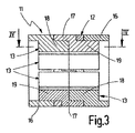
図3は、巻線を備えていない状態のローターの図2の線III−IIIに沿った断面図であり、
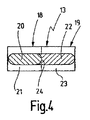
図4は、ローターの歯部の図3の線IV−IVに沿った断面図であり、
図5は、図1のローターを中央で分離して示す分解斜視図であり、この場合に各ローター半部はそれぞれ、異なる構造の2つのモジュールを含んでおり、
図6は、1つのローター半部を図5の矢印VIの方向で見た端面図であり、
図7は、図6の線VII−VIIに沿った断面図であり、
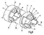
図8は、図5の1つのローター半部の分解斜視図であり、
図9は、図8の左側のモジュールの矢印IXの方向で見た端面図であり、
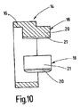
図10は、図9の線X−Xに沿った断面図であり、
図11は、図8の右側のモジュールの矢印XIの方向で見た端面図であり、
図12は、図11の線XII−XIIに沿った断面図であり、
図13は、軸線方向の構成寸法を短くされたローターを巻線のない状態で示した分解斜視図であり、
図14は、図13のローターの斜視図であり、
図15は、図14のローターの端面図であり、
図16は、図15の線XVI−XVIに沿った断面図であり、
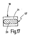
図17は、図16の線XVII−XVIIに沿った断面図である。
Next, the present invention will be described in detail based on illustrated embodiments. In the drawing
FIG. 1 is a perspective view showing a rotor made of SMC-material having a large axial dimension for an inner rotor type motor without winding.
FIG. 2 is a plan view of the rotor with windings as seen from the direction of arrow II in FIG.
FIG. 3 is a cross-sectional view of the rotor without windings, taken along line III-III in FIG.
4 is a cross-sectional view of the teeth of the rotor taken along line IV-IV in FIG.
FIG. 5 is an exploded perspective view showing the rotor of FIG. 1 separately in the center, in which each half of the rotor includes two modules of different structure,
6 is an end view of one rotor half as seen in the direction of arrow VI in FIG.
7 is a cross-sectional view taken along line VII-VII in FIG.
8 is an exploded perspective view of one rotor half of FIG.
FIG. 9 is an end view of the module on the left side of FIG. 8 viewed in the direction of arrow IX.
FIG. 10 is a cross-sectional view taken along line XX of FIG.
FIG. 11 is an end view of the module on the right side of FIG. 8 viewed in the direction of arrow XI.
12 is a cross-sectional view taken along line XII-XII in FIG.
FIG. 13 is an exploded perspective view showing a rotor having a shortened configuration dimension in the axial direction without windings;
14 is a perspective view of the rotor of FIG.
15 is an end view of the rotor of FIG.
FIG. 16 is a cross-sectional view taken along line XVI-XVI in FIG.
FIG. 17 is a cross-sectional view taken along line XVII-XVII in FIG.
図1乃至図3において、三相多極ブラシレス式、例えば三相4極ブラシレス式のインナーローター型直流モーターの固定子として用いられる主要構成要素(メインエレメント)は、電気機械若しくは電動機械の主要構成要素のための実施例として斜視図、端面図並びに断面図で示してある。固定子は磁束が通る、つまり透磁性のSMC−材料(Soft Magnetic Powder Iron Composite[軟磁性鉄粉体])から製造されたSMC−構成部分11を有しており、SMC−構成部分は磁路ヨーク若しくは磁路リング12、及び該磁路リング12と一体成形された内側へ突出する歯部13を備えており、該歯部(突極)は等角度間隔で全周に分配されていて、図2に概略的に示す固定子巻線10を保持しており、固定子巻線は個別の環状コイル101として歯部13に巻き付けられている。SMC−構成部分11は、個別に製造されかつ軸線方向で互いに合致して(整合して)互いに接合された全体で4つのモジュールから成っており、これらのうちのそれぞれ2つは互いに同一に形成されていて、モジュール軸線によって規定された平面内で互いに180°反転され、つまり互いに向かい合わせて接合されている。この場合に同一の2つのモジュールは外側モジュール14として外側に位置しており、別の同一の2つのモジュールは中間モジュール15として軸線方向で外側モジュール14間に配置されている。モジュール14,15の成形のために、SMC−鉄粉体は、外側モジュール14若しくは中間モジュール15の形のチャンバーを有する成形型若しくは金型内で圧縮され、この場合に圧縮はモジュール14,15の軸線方向で行われ、次いで熱処理を施される。モジュール14,15は約7.3g/cm3の密度若しくはそれよりも高い密度に圧縮される。熱処理は大気圧中において約500℃で約30分にわたって行われる。モジュール14,15の鉄粉体の所定の高い密度を得るために、各モジュール14,15は、寸法比(aspect ratio)が1:15の限界値を超えないように形成されている。寸法比は、プレス方向(縦方向)に対して横方向での圧縮成形体の最小寸法とプレス方向での圧縮成形体の寸法との比を意味している。モジュール14,15において鉄粉末の圧縮をモジュール14,15の軸線方向(縦方向)で行うので、個別のモジュール14,15の軸線方向の寸法は、寸法比がモジュールのどの箇所でも所定の最小比よりも小さくならないように選ばれている。
1 to 3, a main component (main element) used as a stator of a three-phase multipole brushless type, for example, a three-phase four-pole brushless type inner rotor type DC motor is a main configuration of an electric machine or an electric machine. An embodiment for the element is shown in perspective, end view and cross-sectional view. The stator has an SMC-
モジュール14,15はそれぞれ、1つの環状の磁路部材若しくは磁路片16,17及び該磁路片16,17内に等角度間隔に分配された同一数のモジュール歯部18,19を有している。各磁路片16,17は、磁路リング12の軸線方向の4つの区分のうちのそれぞれ1つの区分を形成しており、モジュール歯部18,19は、片側で所属の磁路片16,17を超えて突出していて、モジュール14,15の組み立てられた状態で構成部分11の歯部13を形成している。
Each of the
図8には、同一の両方の外側モジュール14及び同一の両方の中間モジュール15のそれぞれ1つを斜視図で示してある。図9及び図10は外側モジュール14を端面若しくは縦断面で示している。図11及び図12は中間モジュール15を端面若しくは縦断面で示している。
FIG. 8 shows a perspective view of each one of both identical
外側モジュール14はすでに前に述べてあるように、磁路片16の内周面に互いに所定の同一の角度間隔でずらして配置された、即ち等角度間隔に分配された3つのモジュール歯部18を備えており、該モジュール歯部は磁路片16と一体に成形されている。各モジュール歯部18は歯頸部若しくは歯シャフト20及び歯足部21を有しており、歯足部は歯シャフト20の、磁路片16と逆の側の端部に配置されていて、歯シャフト20の、軸線方向に延びる互いに相対する縦側(長手縁部)で、つまり周方向で歯シャフト20を越えて突出している。歯足部21は軸線方向で歯シャフト20と同じ長さを有している。
歯シャフト20は、図17に示してあるように端面側で丸みを付けられている。歯シャフト20及び歯足部21は片側で、軸線方向の一部分にわたって、実施例では軸線方向の長さの半分にわたって磁路片16を越えて突出している。モジュール歯部18の数はSMC−構成部分11の磁路リング12に設けられる歯部13の総数の半分の数である。
As already described, the
The
図11及び図12には、中間モジュール15の端面若しくは縦断面を示してある。磁路片17においても、3つの歯部19を磁路片17の内周面(内壁)に等角度間隔に分配して一体に成形してある。モジュール歯部19の数はSMC−構成部分11の磁路リング12に設けられる歯部13の総数の半分の数である。
外側モジュール14と同じ形式で、各モジュール歯部19は、磁路片16のモジュール歯部18の場合と同様に、歯頸部若しくは歯シャフト22及び歯足部23を有している。モジュール歯部19は、モジュール歯部18と同じ軸線方向長さを有していて、軸線方向の所定の長さにわたって磁路片17の端面を超えて突出しており、歯シャフト22から磁路片17への移行面は、外側モジュール14における移行面よりも小さくなっている。歯シャフト22の、磁路片17の外側に位置する端面部は、外側モジュールのモジュール歯部18の歯シャフト20と同様に丸みを付けられている。歯シャフト22の、磁路片17の内側に位置する端面部は、凹面状の湾曲部24を備えており、該湾曲部(凹状湾曲部)は歯シャフト22の逆の側、つまり前記外側の端面部の丸み部若しくは外側モジュール14の歯シャフト20の端面部の丸み部と同じ湾曲半径若しくは円弧半径を有している。歯足部23は、歯シャフト22の湾曲部24を備える端面部で歯シャフト22に対して短くされ、つまり後退していて、図12及び図4に示してあるように、湾曲部24のもっと深い箇所までしか達していない。
11 and 12 show an end surface or a longitudinal section of the
In the same form as the
図8及び図12に示してあるように、中間モジュール15の磁路片17は互いに等角度間隔に分配された3つの切欠部25を有しており、該切欠部は、磁路片17の、モジュール歯部19の設けられている箇所の端面から引っ込めて形成されている。切欠部25は軸線方向及び周方向で同一の寸法を有している。切欠部はモジュール歯部19間に配置されている。図5に示してあるように、切欠部25は、他方の中間モジュール15の磁路片17の、モジュール歯部19を備える領域を受容するようになっている。これによって、磁路片17とモジュール歯部19との間の十分に大きな結合面が得られ、かつ互いに接合される中間モジュール15間の相対回動不能な剛性的な若しくは確実な結合が達成されている。
As shown in FIGS. 8 and 12, the
SMC−粉体の軸線方向で圧縮してモジュール14,15を成形する場合に所定の寸法比をできるだけ大きく設定するために、磁路片16,17の半径方向の寸法若しくは厚さを6mmに選び、かつ磁路片16,17の長さを約25mmに選んであり、このことは寸法比を約1:4にしている。モジュール14,15の最も危険な箇所では、つまり約2mmの厚さの薄い歯足部21,23の箇所では、許容範囲内にある約1:12の寸法比である。
In order to set the predetermined dimensional ratio as large as possible when molding the
図1及び図3に示すSMC−構成部分11を成形するためには、すでに述べてあるように、外側モジュール14と中間モジュール15とは互いに軸線方向でつなぎ合わされる。このために図8に示してあるように、まず中間モジュール15を軸線方向で外側モジュール14に接合(装着)し、それもモジュール歯部18とモジュール歯部19とを互いに合致させて行う。矢印で暗示する接合過程若しくは接合運動の終端領域で、モジュール歯部18の丸み部をモジュール歯部19の凹面状の湾曲部24内に入り込ませて、歯足部21,23は磁路片16,17の互いに向き合わされた端面と同様に突き合わせて面接触させられる。歯シャフト20の丸み部を歯シャフト22の湾曲部24内に係合させる、つまり入り込ませることによって、両方のモジュール14,15の相対的な回動は防止され、このことはモジュール歯部18,19から構成された歯部13上への環状コイルの取り付けを容易にしている。この場合に鉄心若しくは構成部分11の各歯部13は、軸線方向で半部のモジュール歯部18及びモジュール歯部19に形成されている。次いで各歯部13に固定子巻線10の環状コイル101を、図2に概略的に示してあるように巻き付けて形成するようになっている。
In order to form the SMC-
SMC−構成部分11の、それぞれ1つの外側モジュール14と1つの中間モジュール15とを組み合わせて成形された2つの構成要素(構成ユニット)は、それぞれ、歯部13の総数の半数を有し、ひいては固定子巻線10の環状コイル101の総数の半数を有していて、互いに軸線方向で接合されて、固定子巻線10を備えたSMC−構成部分11を形成するようになっており、この場合に、外側モジュール14及び中間モジュール15から成る一方の構成要素は、接合の前に、モジュール軸線によって規定された1つの平面内で、外側モジュール14及び中間モジュール15から成る他方の構成要素に対して180°反転させられ、これによって両方の中間モジュール15は互いに向き合わされており、このことは図5の斜視図に示してある。一方の外側モジュール14及びこれに堅く結合された中間モジュール15は、さらに、他方の外側モジュール14及びこれに堅く結合された中間モジュール15に対して周方向に所定の角度にわたって回動させられ、これによって、SMC−構成部分11の一方の構成要素の歯部13は、該SMC−構成部分11の他方の構成要素の歯部13間の空間部に相対して位置している。回動角は、6つの歯部13を有する図示のSMC−構成部分11において60°である。つまり回動角は、SMC−構成部分11に設けられている歯部13の総数をNとすると、360°/Nである。SMC−構成部分11の両方の構成要素は、図5に示すように整合した位置で、矢印で示すように軸線方向で互いに押し合わされ、この場合に、一方の中間モジュール15の磁路片17のモジュール歯部18を保持する各領域若しくは区分は、他方の中間モジュール15の各切欠部25内に形状結合的に、つまり形状による束縛を伴って入り込むようになっている。該接合過程の終了時点では、固定子はまだ図1及び図3に示してあるように固定子巻線10を備えていない状態である。
The two components (component units) of the SMC-
SMC−構成部分11の前述の構成は、同一構造形式の電気機械若しくは電動機、特に直流モーターを、構成的及び製作技術的な変更なしに軸線方向の短い長さで実施することが可能であるという利点を有している。このために図13乃至図16に示してあるように、外側モジュール14間の両方の中間モジュール15は、省略されており、外側モジュール14は、図13に矢印によって暗示するように軸線方向で互いに直接に接合される。この場合に両方の外側モジュール14は、上述のように互いに相対的に位置決めされ、これによってモジュール歯部18を軸線方向に突出させる端面は、互いに向き合わされており、一方の外側モジュール14のモジュール歯部18は他方のモジュール歯部18間の空間部と相対して位置している。両方の外側モジュールを互いに接合する前に、固定子巻線の環状コイルは両方の外側モジュール14のモジュール歯部18上に巻き付け成形される。このようにして形成される軸線方向長さの短いSMC−構成部分11は図14に斜視図で、図15に端面図で、かつ図16に断面図で示してある。互いに接合されかつ互いに相対回動不能に結合された両方の外側モジュール14の磁路片16は、軸線方向で短くされた固定子の磁路リング11′を形成しており、両方の外側モジュール14の各モジュール歯部18は、軸線方向で短くされた固定子のそれぞれ1つの歯部13を形成している。図示の実施例で各外側モジュール14はそれぞれ3つのモジュール歯部18を保持しており、したがって軸線方向で短くされた固定子に総数6つの歯部13′を形成している。
The above-described configuration of the SMC-
本発明は、インナーローター型電動機のための図示の固定子に限定されるものではなく、同様にアウターローター型電動機のための固定子にも適合されるものである。さらに本発明に基づく構成は、電気機械若しくは電動機のための回転子にも、同じ利点を伴って用いられるものである。 The present invention is not limited to the illustrated stator for the inner rotor type electric motor, but is similarly adapted to a stator for the outer rotor type electric motor. Furthermore, the configuration according to the invention can be used with the same advantages in rotors for electric machines or motors.
10 固定子巻線、 11 SMC−構成部分11、 12 磁路リング、 13 歯部、 14 外側モジュール、 15 中間モジュール、 16,17 磁路片、 18,19 モジュール歯部、 20 歯シャフト、 21 歯足部、 24 湾曲部、 25 切欠部
10 Stator Winding, 11 SMC-
Claims (10)
Applications Claiming Priority (2)
| Application Number | Priority Date | Filing Date | Title |
|---|---|---|---|
| DE102004039180A DE102004039180A1 (en) | 2004-08-12 | 2004-08-12 | Main element for an electrical machine |
| PCT/EP2005/053099 WO2006018346A1 (en) | 2004-08-12 | 2005-06-30 | Electric machine main element |
Publications (1)
| Publication Number | Publication Date |
|---|---|
| JP2008509647A true JP2008509647A (en) | 2008-03-27 |
Family
ID=34982566
Family Applications (1)
| Application Number | Title | Priority Date | Filing Date |
|---|---|---|---|
| JP2007525273A Pending JP2008509647A (en) | 2004-08-12 | 2005-06-30 | Main components for electrical machines |
Country Status (5)
| Country | Link |
|---|---|
| US (1) | US7705511B2 (en) |
| EP (1) | EP1779493B1 (en) |
| JP (1) | JP2008509647A (en) |
| DE (2) | DE102004039180A1 (en) |
| WO (1) | WO2006018346A1 (en) |
Cited By (1)
| Publication number | Priority date | Publication date | Assignee | Title |
|---|---|---|---|---|
| WO2011034336A3 (en) * | 2009-09-18 | 2011-07-14 | Bang Deok Je | Direct-drive electric equipment |
Families Citing this family (6)
| Publication number | Priority date | Publication date | Assignee | Title |
|---|---|---|---|---|
| DE102006020435A1 (en) * | 2006-05-03 | 2007-11-08 | Bayerische Motoren Werke Ag | Electrical machine e.g. synchronous electrical machine, for converting electrical energy into mechanical energy, has coil forming coil end, and end of stator or rotor formed differently with respect to center of stator or rotor |
| TR201102178T1 (en) * | 2008-10-30 | 2011-08-22 | Arçeli̇k Anoni̇m Şi̇rketi̇ | Segmented stator. |
| DE202010015364U1 (en) * | 2010-11-11 | 2012-02-17 | Hans-Peter Wyremba | Brushless electric motor or generator in shell construction |
| US10097070B1 (en) * | 2012-03-23 | 2018-10-09 | Coleridge Design Associates Llc | DC induction motor with stator coil driven by a unidirectional field current |
| FR3018642B1 (en) * | 2014-03-12 | 2017-08-25 | Valeo Equip Electr Moteur | ROTATING ELECTRIC MACHINE |
| DE102015013028A1 (en) | 2015-10-09 | 2017-04-13 | Minebea Co., Ltd. | Stator body for an internal rotor |
Family Cites Families (6)
| Publication number | Priority date | Publication date | Assignee | Title |
|---|---|---|---|---|
| WO2002058210A1 (en) | 2001-01-18 | 2002-07-25 | Robert Bosch Gmbh | Component for the rotor or stator of an electrical machine |
| JP2002233085A (en) | 2001-02-02 | 2002-08-16 | Oriental Motor Co Ltd | Stator for motor and its assembling method |
| US6946771B2 (en) * | 2002-07-10 | 2005-09-20 | Quebec Metal Powders Limited | Polyphase claw pole structures for an electrical machine |
| JP2004120958A (en) * | 2002-09-27 | 2004-04-15 | Aisin Seiki Co Ltd | Stator of brushless motor and its manufacturing method |
| DE10319190A1 (en) | 2003-04-29 | 2004-11-18 | Robert Bosch Gmbh | Electrical machine |
| US7567010B1 (en) * | 2008-04-10 | 2009-07-28 | Burgess-Norton Mfg. Co., Inc | Modular electric motor with stackable stator poles |
-
2004
- 2004-08-12 DE DE102004039180A patent/DE102004039180A1/en not_active Withdrawn
-
2005
- 2005-06-30 US US11/659,838 patent/US7705511B2/en not_active Expired - Fee Related
- 2005-06-30 EP EP05763934A patent/EP1779493B1/en not_active Expired - Fee Related
- 2005-06-30 DE DE502005010808T patent/DE502005010808D1/de active Active
- 2005-06-30 JP JP2007525273A patent/JP2008509647A/en active Pending
- 2005-06-30 WO PCT/EP2005/053099 patent/WO2006018346A1/en active Application Filing
Cited By (3)
| Publication number | Priority date | Publication date | Assignee | Title |
|---|---|---|---|---|
| WO2011034336A3 (en) * | 2009-09-18 | 2011-07-14 | Bang Deok Je | Direct-drive electric equipment |
| JP2013505697A (en) * | 2009-09-18 | 2013-02-14 | コリア エレクトロテクノロジー リサーチ インスティチュート | Direct drive electrical equipment |
| US9157416B2 (en) | 2009-09-18 | 2015-10-13 | Korea Electrotechnology Research Institute | Direct-drive electric machine configured with a plural-module combination structure |
Also Published As
| Publication number | Publication date |
|---|---|
| EP1779493B1 (en) | 2011-01-05 |
| EP1779493A1 (en) | 2007-05-02 |
| WO2006018346A1 (en) | 2006-02-23 |
| DE502005010808D1 (en) | 2011-02-17 |
| US20080042511A1 (en) | 2008-02-21 |
| DE102004039180A1 (en) | 2006-02-23 |
| US7705511B2 (en) | 2010-04-27 |
Similar Documents
| Publication | Publication Date | Title |
|---|---|---|
| JP2008509647A (en) | Main components for electrical machines | |
| JP2006524978A (en) | Electric machine | |
| JP4887656B2 (en) | Rotating electric machine and car equipped with it | |
| JP2011019360A (en) | Stator and method of manufacturing the same | |
| WO2015052964A1 (en) | Rotary electric machine and production method therefor | |
| US20090243421A1 (en) | Electric motor stator and permanent magnet-type electric motor using the same | |
| JP2005237086A (en) | Axial motor and manufacturing method therefor | |
| JP2009100489A (en) | Slotless rotary electric machine | |
| JP2005261188A (en) | Core for rotating machine and rotating machine | |
| US20030151327A1 (en) | Process for forming the stack of metallic laminations for the stator of an eletric motor and the stack of metallic laminations | |
| JPH11178259A (en) | Motor stator and its manufacture | |
| JPH09322439A (en) | Stator for dynamo-electric machine and its manufacture | |
| KR20120090555A (en) | Amorphous stator, electric motor using the same, and producing method thereof | |
| JP6057777B2 (en) | Stator, hermetic compressor and rotary machine including the stator, and mold | |
| JP3657155B2 (en) | 2-axis synchronous motor | |
| JP2015171193A (en) | Armature core and armature | |
| JP2008043139A (en) | Electric motor | |
| JP5134935B2 (en) | Electric motor | |
| JP2008199795A (en) | Electric motor | |
| JPS5959057A (en) | Rotor for synchronous machine | |
| JP2004040948A (en) | Motor | |
| JP3621894B2 (en) | Stabilizer for internal motor | |
| KR100595729B1 (en) | Stator structure for inner rotor type electromotor and method threrof | |
| JP5286121B2 (en) | Toroidal winding motor | |
| US20200099262A1 (en) | Polyphase claw pole motor |
Legal Events
| Date | Code | Title | Description |
|---|---|---|---|
| A131 | Notification of reasons for refusal |
Free format text: JAPANESE INTERMEDIATE CODE: A131 Effective date: 20090918 |
|
| A02 | Decision of refusal |
Free format text: JAPANESE INTERMEDIATE CODE: A02 Effective date: 20100310 |