JP2008507301A - Leakage prevention enclosing means comprising a spring member - Google Patents
Leakage prevention enclosing means comprising a spring member Download PDFInfo
- Publication number
- JP2008507301A JP2008507301A JP2007519292A JP2007519292A JP2008507301A JP 2008507301 A JP2008507301 A JP 2008507301A JP 2007519292 A JP2007519292 A JP 2007519292A JP 2007519292 A JP2007519292 A JP 2007519292A JP 2008507301 A JP2008507301 A JP 2008507301A
- Authority
- JP
- Japan
- Prior art keywords
- container
- male
- female
- spring member
- web
- Prior art date
- Legal status (The legal status is an assumption and is not a legal conclusion. Google has not performed a legal analysis and makes no representation as to the accuracy of the status listed.)
- Pending
Links
Images


Classifications
-
- B—PERFORMING OPERATIONS; TRANSPORTING
- B65—CONVEYING; PACKING; STORING; HANDLING THIN OR FILAMENTARY MATERIAL
- B65D—CONTAINERS FOR STORAGE OR TRANSPORT OF ARTICLES OR MATERIALS, e.g. BAGS, BARRELS, BOTTLES, BOXES, CANS, CARTONS, CRATES, DRUMS, JARS, TANKS, HOPPERS, FORWARDING CONTAINERS; ACCESSORIES, CLOSURES, OR FITTINGS THEREFOR; PACKAGING ELEMENTS; PACKAGES
- B65D33/00—Details of, or accessories for, sacks or bags
- B65D33/16—End- or aperture-closing arrangements or devices
- B65D33/25—Riveting; Dovetailing; Screwing; using press buttons or slide fasteners
- B65D33/2508—Riveting; Dovetailing; Screwing; using press buttons or slide fasteners using slide fasteners with interlocking members having a substantially uniform section throughout the length of the fastener; Sliders therefor
- B65D33/2541—Riveting; Dovetailing; Screwing; using press buttons or slide fasteners using slide fasteners with interlocking members having a substantially uniform section throughout the length of the fastener; Sliders therefor characterised by the slide fastener, e.g. adapted to interlock with a sheet between the interlocking members having sections of particular shape
-
- B—PERFORMING OPERATIONS; TRANSPORTING
- B65—CONVEYING; PACKING; STORING; HANDLING THIN OR FILAMENTARY MATERIAL
- B65D—CONTAINERS FOR STORAGE OR TRANSPORT OF ARTICLES OR MATERIALS, e.g. BAGS, BARRELS, BOTTLES, BOXES, CANS, CARTONS, CRATES, DRUMS, JARS, TANKS, HOPPERS, FORWARDING CONTAINERS; ACCESSORIES, CLOSURES, OR FITTINGS THEREFOR; PACKAGING ELEMENTS; PACKAGES
- B65D33/00—Details of, or accessories for, sacks or bags
- B65D33/16—End- or aperture-closing arrangements or devices
- B65D33/24—End- or aperture-closing arrangements or devices using self-locking integral or attached closure elements, e.g. flaps
-
- B—PERFORMING OPERATIONS; TRANSPORTING
- B65—CONVEYING; PACKING; STORING; HANDLING THIN OR FILAMENTARY MATERIAL
- B65D—CONTAINERS FOR STORAGE OR TRANSPORT OF ARTICLES OR MATERIALS, e.g. BAGS, BARRELS, BOTTLES, BOXES, CANS, CARTONS, CRATES, DRUMS, JARS, TANKS, HOPPERS, FORWARDING CONTAINERS; ACCESSORIES, CLOSURES, OR FITTINGS THEREFOR; PACKAGING ELEMENTS; PACKAGES
- B65D33/00—Details of, or accessories for, sacks or bags
- B65D33/16—End- or aperture-closing arrangements or devices
- B65D33/25—Riveting; Dovetailing; Screwing; using press buttons or slide fasteners
-
- Y—GENERAL TAGGING OF NEW TECHNOLOGICAL DEVELOPMENTS; GENERAL TAGGING OF CROSS-SECTIONAL TECHNOLOGIES SPANNING OVER SEVERAL SECTIONS OF THE IPC; TECHNICAL SUBJECTS COVERED BY FORMER USPC CROSS-REFERENCE ART COLLECTIONS [XRACs] AND DIGESTS
- Y10—TECHNICAL SUBJECTS COVERED BY FORMER USPC
- Y10T—TECHNICAL SUBJECTS COVERED BY FORMER US CLASSIFICATION
- Y10T24/00—Buckles, buttons, clasps, etc.
- Y10T24/15—Bag fasteners
-
- Y—GENERAL TAGGING OF NEW TECHNOLOGICAL DEVELOPMENTS; GENERAL TAGGING OF CROSS-SECTIONAL TECHNOLOGIES SPANNING OVER SEVERAL SECTIONS OF THE IPC; TECHNICAL SUBJECTS COVERED BY FORMER USPC CROSS-REFERENCE ART COLLECTIONS [XRACs] AND DIGESTS
- Y10—TECHNICAL SUBJECTS COVERED BY FORMER USPC
- Y10T—TECHNICAL SUBJECTS COVERED BY FORMER US CLASSIFICATION
- Y10T24/00—Buckles, buttons, clasps, etc.
- Y10T24/26—Slit closing means including guides on opposite edges of slit and slidable bridging component
- Y10T24/262—Slit closing means including guides on opposite edges of slit and slidable bridging component with hand-actuated lever for shifting bridging component
-
- Y—GENERAL TAGGING OF NEW TECHNOLOGICAL DEVELOPMENTS; GENERAL TAGGING OF CROSS-SECTIONAL TECHNOLOGIES SPANNING OVER SEVERAL SECTIONS OF THE IPC; TECHNICAL SUBJECTS COVERED BY FORMER USPC CROSS-REFERENCE ART COLLECTIONS [XRACs] AND DIGESTS
- Y10—TECHNICAL SUBJECTS COVERED BY FORMER USPC
- Y10T—TECHNICAL SUBJECTS COVERED BY FORMER US CLASSIFICATION
- Y10T24/00—Buckles, buttons, clasps, etc.
- Y10T24/45—Separable-fastener or required component thereof [e.g., projection and cavity to complete interlock]
- Y10T24/45152—Each mating member having similarly shaped, sized, and operated interlocking or intermeshable face
- Y10T24/45157—Zipper-type [e.g., slider]
- Y10T24/45168—Zipper-type [e.g., slider] for container [e.g., bag]
Abstract
【解決手段】
封入手段は、封入手段のシール作用を高めるためのスプリング部材を含む。封入手段はフレキシブル容器での使用に特に適している。封入手段は、それぞれが雄および雌フック部分を含む雄および雌封入要素を含む。雄および雌フック部分は相互に係合して、フレキシブル容器の漏出防止シールとなる。スプリング部材は封入要素の一方に装着されて、他の封入要素のフック部分に作用して、封入手段のシール作用を高めるものである。
【選択図】図3[Solution]
The enclosing means includes a spring member for enhancing the sealing action of the enclosing means. The enclosing means is particularly suitable for use in a flexible container. The encapsulating means includes male and female encapsulating elements that each include male and female hook portions. The male and female hook portions engage each other to provide a leak-proof seal for the flexible container. The spring member is attached to one of the enclosure elements and acts on the hook portion of the other enclosure element to enhance the sealing action of the enclosure means.
[Selection] Figure 3
Description
本発明は概して封入手段、より詳しくはスプリング部材を備える再シール可能な漏出防止封入手段に関連する。本発明は、プラスチックバッグを含むフレキシブルな保管容器の締結に特に適している。 The present invention relates generally to a sealing means, and more particularly to a resealable leak-proof sealing means comprising a spring member. The invention is particularly suitable for fastening flexible storage containers including plastic bags.
プラスチックバッグを含む容器の封入のための封入手段の使用は、概ねよく知られている。封入手段と関連の容器は一般的に、熱可塑性材料で形成される。押出成形による封入手段の製造は、封入手段の技術の熟練者には概ね周知である。封入手段は概ね、押出成形されてから容器に装着されるか、容器と一体的に形成される。 The use of encapsulation means for the encapsulation of containers including plastic bags is generally well known. The container associated with the enclosing means is generally formed of a thermoplastic material. The manufacture of encapsulation means by extrusion is generally well known to those skilled in the art of encapsulation means. The sealing means is generally extruded and then attached to the container or formed integrally with the container.
これらの手段は再シール可能であって、容器の再使用を可能にする。概して、封入手段は容器内部からの開封に対しては比較的高い抵抗を持つのに対して、外部からは比較的容易に開封できる。しかし状況によっては、外部からの開封に対しても高い抵抗を付与することが封入手段にとって望ましいこともある。 These means are resealable and allow the container to be reused. In general, the sealing means has a relatively high resistance to opening from the inside of the container, but can be opened from the outside relatively easily. However, depending on the situation, it may be desirable for the sealing means to provide a high resistance to opening from the outside.
内部の中身と外部の環境の変化のため、容器の内部は比較的高圧または比較的低圧の状態にある。内部または外部からの開封に対して適切な抵抗を付与して容器を封入状態に保持するため、封入手段は一般的に係合フックの組合せを使用する。封入手段によっては、係合フックの間の接触面が容器の主要シールとなる。この設計の難点の一つは、外部からの開封とともに閉塞が容易な封入を維持しながら、確実な封入を行い、気密または漏出防止のシールとすることである。場合によっては、フックの若干の変形のため、または、図33に見られるように封入手段が使用される状態によってフックが相互に接触しないため、係合フックが相互に接触していないが閉塞状態にあるということも起こる。閉塞位置において係合フックが密着係合していない場合には、封入手段は適切な気密または漏出防止シールとはならない。 Due to changes in the internal contents and the external environment, the interior of the container is at a relatively high or relatively low pressure. Enclosure means typically use a combination of engagement hooks to provide adequate resistance to internal or external opening and hold the container in an enclosed state. Depending on the sealing means, the contact surface between the engagement hooks becomes the main seal of the container. One of the disadvantages of this design is that it is sealed tightly while maintaining sealing that is easy to close together with opening from the outside, to provide an airtight or leakproof seal. In some cases, the engagement hooks are not in contact with each other, but are closed because of some deformation of the hooks, or because the hooks do not contact each other due to the use of the encapsulation means as seen in FIG. It also happens to be. If the engagement hook is not in tight engagement in the closed position, the enclosing means will not be a proper hermetic or leak-proof seal.
以上を鑑みて、本発明はフレキシブル容器のための改良型封入手段を提供する。より詳しく述べると、本発明は、このような封入手段を含むフレキシブル容器のための封入動作を改良する封入手段と、封入手段を製造する方法とに関連する。 In view of the above, the present invention provides an improved encapsulation means for a flexible container. More particularly, the present invention relates to an encapsulating means for improving the enclosing operation for a flexible container including such an enclosing means and a method for manufacturing the enclosing means.
本発明によれば、封入手段は相互に係合するとともに所定の長さだけ延在する雄および雌封入要素を備える。一般的にこの長さは、封入手段が装着される予定のフレキシブル容器の幅である。雄および雌封入要素は、閉塞位置において封入手段の係合を容易にするフック部分を含む。さらに、封入要素の少なくとも一方は、封入手段のシール動作を容易にするスプリング部材を含む。スプリング部材は、係合フック部分の間の接触力を高めてフック部分を一層密着させることにより、封入手段のシールを強化する。また、容器の中身の漏出を阻止する付加的妨害物となる付加的接触面を設けることにより、シール作用を高める。 According to the invention, the enclosing means comprise male and female enclosing elements that engage with each other and extend a predetermined length. In general, this length is the width of the flexible container to which the sealing means is to be attached. The male and female encapsulation elements include hook portions that facilitate engagement of the encapsulation means in the closed position. Furthermore, at least one of the enclosing elements includes a spring member that facilitates the sealing action of the enclosing means. The spring member enhances the sealing of the enclosing means by increasing the contact force between the engaging hook portions and further bringing the hook portions into close contact. In addition, the sealing action is enhanced by providing an additional contact surface that provides an additional obstruction to prevent leakage of the contents of the container.
開示発明の別の実施例によれば、封入手段は多数のスプリング部材を含む。付加的スプリング部材は、雄と雌のいずれかの封入要素に装着される。付加的スプリング部材を設けることにより、封入要素はより確実に係合してより広い接触面が設けられ、バッグの中身の漏出を阻止する。 According to another embodiment of the disclosed invention, the enclosing means includes a number of spring members. The additional spring member is attached to either the male or female encapsulation element. By providing an additional spring member, the encapsulation element is more securely engaged and a wider contact surface is provided to prevent leakage of the bag contents.
以下の発明の説明を読み、添付図面を参考にすれば、本発明のこれらおよび他の特徴と長所は一層容易に明らかとなるだろう。 These and other features and advantages of the present invention will become more readily apparent upon reading the following description of the invention and referring to the accompanying drawings.
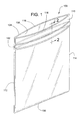
図1は、シール可能な長手方向延在封入手段102を含むプラスチックバッグ100の形の、本発明によるフレキシブル容器を示す。封入手段102は、ほぼバッグ100の幅にわたって延在する。バッグ100は、バッグ100の底部106がU字に畳まれた肉薄のプラスチックフィルム104から形成される。フィルム104は容器の側壁108,110を形成する。一般的に、側壁108,110は、垂直エッジ112,114で熱シールされることにより、容器を形成する。封入手段102の端部は熱シールされる。側壁108,110は封入手段102よりも延出して口部116,118となり、バッグ100、より詳しくは封入手段102の開封を簡単にする。封入手段102全体は一般的に、エッジ112からエッジ114のように、バッグの一方のエッジから始まりバッグの他方のエッジへ向かって操作することにより閉塞される。
FIG. 1 shows a flexible container according to the invention in the form of a
図2は、本発明の一実施例による、非閉塞状態で描かれた漏出防止封入手段102の断面図である。封入手段102は、所定の長さにわたって係合する雌および雄封入要素130,132を包含する。雌および雄封入要素103,132は押出成形されてから容器の側壁に装着される。
FIG. 2 is a cross-sectional view of the leak-proof encapsulation means 102 depicted in an unoccluded state, according to one embodiment of the present invention. The encapsulation means 102 includes female and
雌封入要素130は、ベース部分134と、離間して平行に配置された一対のウェブ136,138と、一対の雌フック部分140,142と、スプリング部材144とを含む。ウェブ136,138はベース部分134から延出して、それぞれ雌フック部分140,142を含み、これを終端とする。雌フック部分140,142は相互に近接延出している。雌フック部分140,142は、雌および雄封入要素130,132の閉塞中に雌封入要素130、より詳しくは雌フック部分140,142を案内する役割を果たすガイド面146,148を含む。スプリング部材144は、ベース部分134から延出する。一般的に、雌封入要素130のベース部分134とウェブ136,138とスプリング部材144とは、単体から一体的に形成される。
The
雌封入要素130と係合および当接するのに適した雄封入要素132は、ベース部分150と、離間して平行に配置された一対のウェブ152,154と、一対の雄フック部分156,158と、離間して平行に配置された一対のガイドウィング160,162とを含む。ウェブ152,154はベース部分150から延出し、それぞれ雄フック部分156,158を含み、これを終端とする。雄フック部分156,158は相互に離間延出し、それぞれ雌フック部分140,142と嵌合するのに適している。雄フック部分156,158は、雌および雄封入要素130,132の閉塞中に、雄封入要素132、より詳しくは雄フック部分156,158を案内する役割を果たすガイド面164,166を含む。ガイドウィング160,162はベース部分150から延出して、ウェブ152,154と平行に配置される。一般的に、雄封入要素132のベース部分150とウェブ136,138とガイドウィング160,162とは、単体に一体形成される。
A
図3は、図2の封入手段102を示すが、閉塞位置で描かれている。閉塞位置では、雌フック部分140,142は雄フック部分156,158と係合している。すなわち、概ね接触面168において雌フック部分140が雄フック部分156と嵌合し、概ね接触面170において雌フック部分142が雄フック部分158と嵌合しているのである。嵌合したフック部分の間の接触力は、容器の開封に抵抗する。さらに、フック部分が相互に嵌合する接触面168,170は封入手段102のシールとなる。
FIG. 3 shows the enclosing means 102 of FIG. 2, but depicted in the closed position. In the closed position,
閉塞位置において、封入手段102は容器の内部172と外部174とを画定する。この実施例では、スプリング部材144が容器の内部172に近接延出する。図のように、スプリング部材144は湾曲している。スプリング部材は他の形状を持ってもよいことに言及すべきである。例えば、非閉塞位置においてスプリング部材は略直線部材または「Z字形」部材であってもよい。雌封入要素130のベース部分134から延出するスプリング部材144は、容器の内部172に隣接する雄フック部分158に作用する。雄フック部分158に作用することにより、スプリング部材144は、雄フック部分158と嵌合する雌フック部分142に雄フック部分158を押圧する。そのうえ、雄フック部分158に作用することにより、スプリング部材144は雌フック部分142を雄フック部分158へ引き寄せる。これらの作用により、接触面170では雄フック部分158と雌フック部分142とのより密着した嵌合およびシールが生じる。スプリング部材144は、接触面170のシールを強化するばかりでなく、スプリング部材144が雄フック部分158に作用する接触面176に付加的シールを設ける。こうして、接触面170におけるシール作用を強化するとともに接触面176に付加的シールを設けることにより、スプリング部材144は封入手段102のシール作用をかなり強化する。以下で開示するように、本発明の他の実施例では、封入手段に付加的スプリング部材を追加してもよい。これらの付加的スプリング部材は、バッグの中身を制限するとともにその漏出を防止することによりシールとして作用する付加的接触面となる。スプリング部材はまた、封入要素の嵌合を向上させることにより、係合した雄および雌フック部分の間のシール作用を向上させる。
In the closed position, the closure means 102 defines an
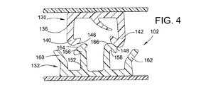
図4〜7は、本発明による封入手段102の概略閉塞手順を示す。図4は閉塞手順の開始を示し、雌フック部分140,142のガイド面146,148と雄フック部分156,158のガイド面164,166が接触を開始する。すなわち、雌フック部分140のガイド面146と雄フック部分156のガイド面164とが相互に接触し始める。雌フック部分142のガイド面148と雄フック部分158のガイド面166とが相互に接触し始める。雌および雄封入要素130,132がこの時点で正確に整合していない場合には、正確な閉塞のための封入手段130,132の整合をガイドウィング160,162が補助する。
4-7 show a schematic closing procedure for the enclosing means 102 according to the invention. FIG. 4 shows the start of the closing procedure, where the guide surfaces 146, 148 of the
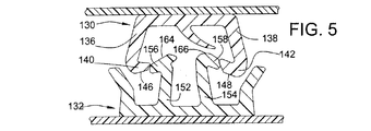
図5では、雌および雄封入要素130,132がともに押圧され始める。封入要素130,132が近接するにつれて、雌フック部分140,142のガイド面146,148のそれぞれは、雄フック部分156,158のガイド面164,166のそれぞれに対して摺動を開始する。雌封入要素130のウェブ136,138が相互から離間するように弾性撓曲を開始し、一方、雄封入要素132のウェブ152,154は相互へ近接するように弾性撓曲を開始する。
In FIG. 5, both the female and
図6では、雌および雄封入要素130,132は図5と比較して相互に近接した状態で押圧される。雌フック部分140,142のガイド面146,148はそれぞれ、雄フック部分156,158のガイド面164,166のそれぞれに対する摺動を続ける。雌封入要素130のウェブ136,138は相互に離間するようにさらに弾性撓曲する。雄封入要素132のウェブ152,154は、相互に近接するようにさらに弾性撓曲する。さらに、雄および雌封入要素130,132が相互に近接し続けると、スプリング部材144が雄フック部分158のガイド面166と接触面176において接触し始める。
In FIG. 6, the female and
図7に図示された閉塞位置では、雌および雄封入要素130,132は係合している。この位置では、雌フック部分140,142はそれぞれ雄フック部分156,158とほぼ嵌合している。さらに、雌封入要素130のウェブ136,138と雄封入要素132のウェブ152,154とは、図4の未撓曲状態とほぼ同様の略未撓曲状態に戻る。しかし、閉塞位置ではウェブの若干の撓曲が存在してもよい。
In the closed position illustrated in FIG. 7, the female and
この閉塞位置では、スプリング部材144は雌封入要素130のベース部分134へほぼ向かうように弾性撓曲している。スプリング部材144の弾性撓曲によってスプリング部材144は接触面176で雄フック部分158に作用し、雄フック部分158を雌フック部分142へ押圧することにより、接触面170におけるシール作用を強化する。スプリング部材144と雄フック部分158との間の接触面176も、付加的シールとなる。
In this closed position, the
雄封入要素132のガイドウィング160,164は、雌および雄封入要素130,132の閉塞を補助する。ガイドウィング160,164は、閉塞中に雌および雄封入要素130,132を相互に近接するように案内および誘導する外側整合部材として設けられている。
The
図8,9は、それぞれ非閉塞および閉塞位置におけるクレーム記載発明の別の実施例を示す。この開示実施例は図2,3の実施例と類似している。しかしこの実施例では、雌封入要素230のベース部分234から延出するスプリング部材244が、容器の外部274へ向かって延出している。図9で最も分かりやすいように、閉塞位置において容器の外部274に隣接する雄フック部分256に、スプリング部材244が作用する。すなわち、スプリング部材244は接触面276でガイド面264に作用するのである。
8 and 9 show another embodiment of the claimed invention in the non-closed and closed positions, respectively. This disclosed embodiment is similar to the embodiment of FIGS. However, in this embodiment, a
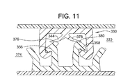
図10,11は、それぞれ非閉塞および閉塞位置における、本発明による封入手段の別の実施例を示す。この実施例は、図2,8の実施例に類似しており、その組合せである。この実施例では、二つのスプリング部材344,378が雌封入要素330のベース部分334から延出する。図11に最も分かりやすく図示されているように、スプリング部材344は、容器の外部374に隣接する雄フック部分356に接触面376で作用する。スプリング部材378は、容器の内部372に隣接する雄フック部分358に接触面380で作用する。
Figures 10 and 11 show another embodiment of the enclosing means according to the present invention in the unoccluded and occluded positions, respectively. This embodiment is similar to the embodiment of FIGS. 2 and 8 and is a combination thereof. In this embodiment, two
図12は、非閉塞位置におけるクレーム記載発明の別の実施例を示す。図12では、雌封入要素430はスプリング部材444を含み、図2に開示されたものと類似している。この実施例の雄封入要素432は、ベース部分450から延出するスプリング部材478を含む。スプリング部材478は、容器の外部474に隣接するウェブ452とガイドウィング460との間に配置され、これらとほぼ平行である。
FIG. 12 shows another embodiment of the claimed invention in the non-closed position. In FIG. 12, the
図13は閉塞位置における図12の実施例を示す。図のように、スプリング部材478は容器の内部472に向かって延出し、ベース部分450に一体的に装着されている。この実施例では、容器の外部474に隣接する雌フック部分440にスプリング部材478が作用する。
FIG. 13 shows the embodiment of FIG. 12 in the closed position. As shown, the
図14,15は、それぞれ非閉塞および閉塞位置で描かれたクレーム記載発明の別の実施例を示す。この実施例は、図12,13の実施例と類似している。この別の実施例も同様に、雌封入要素530のベース部分534から延出するスプリング部材544を含む。しかし、雄封入要素532のベース部分550から延出するスプリング部材578は、容器の外部574に向かって延出する。図13の実施例と同様に、この実施例のスプリング部材578は、容器の外部574に隣接する雌フック部分540に作用する。
Figures 14 and 15 show another embodiment of the claimed invention depicted in the non-closed and closed positions, respectively. This embodiment is similar to the embodiment of FIGS. This alternative embodiment similarly includes a
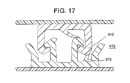
図16は、非閉塞位置で描かれたクレーム請求発明の封入手段の別の実施例を示す。この実施例は、スプリング部材678の配置を除いて、図12の実施例と類似している。この実施例も同様に、雌封入要素630のベース部分634から延出するスプリング部材644を含む。図16に見られるように、この実施例の雄封入要素632は、ベース部分650と、ベース部分650から延出するスプリング部材678とを含む。スプリング部材678は、容器の内部674に隣接するウェブ654とガイドウィング662との間に配置され、これらとほぼ平行である。スプリング部材678は容器の内部672に向かって延出し、ベース部分650に一体的に装着されている。図17は、閉塞位置におけるこの実施例の図である。この実施例では、容器の内部672に隣接する雌フック部分642にスプリング部材678が作用する。
FIG. 16 shows another embodiment of the enclosing means of the claimed invention drawn in the non-closed position. This embodiment is similar to the embodiment of FIG. 12 except for the arrangement of the
図18,19は、それぞれ非閉塞および閉塞位置で描かれたクレーム記載発明の別の実施例である。この実施例は、図16,17の実施例に類似している。この実施例も同様に、雌封入要素730のベース部分734から延出するスプリング部材744を含む。しかしこの実施例では、雄封入要素732のスプリング部材778は容器の外部774に向かって延出している。
18 and 19 are alternative embodiments of the claimed invention depicted in the non-closed and closed positions, respectively. This embodiment is similar to the embodiment of FIGS. This embodiment similarly includes a
図20は、非閉塞位置で描かれたクレーム請求発明の別の実施例を示す。この実施例は図12,18の実施例の組合せである。この実施例も同様に、雌封入要素830のベース部分834から延出して上で説明したように機能するスプリング部材844を含む。しかし、雄封入要素832は、ベース部分850と、相互に向かって延出するとともにベース部分850から延出する二つのスプリング部材878,882とを含む。第1スプリング部材878は、容器の外部874に隣接するウェブ852とガイドウィング860との間に配置されるとともに、これらにほぼ平行である。第2スプリング部材882は、容器の内部872に隣接するウェブ854とガイドウィング862との間に配置されるとともに、これらにほぼ平行である。
FIG. 20 illustrates another embodiment of the claimed invention depicted in a non-closed position. This embodiment is a combination of the embodiments of FIGS. This embodiment also includes a
図21は、閉塞位置で描かれた図20の実施例の追加図である。この実施例では、第1スプリング部材878は、容器の外部874に隣接する雌フック部分840に作用する。第2スプリング部材882は、容器の内部872に隣接する雌フック部分842に作用する。
FIG. 21 is an additional view of the embodiment of FIG. 20 depicted in the closed position. In this embodiment, the
図22,23は、それぞれ非閉塞および閉塞位置で描かれた開示発明の別の実施例を示す。この実施例は、図20,21の実施例と類似している。この実施例も同様に、雌封入要素930のベース部分934から延出するスプリング部材944を含む。しかし、雄封入要素932のベース部分950から延出するスプリング部材978,982は、相互に離間するように延出している。
22 and 23 show another embodiment of the disclosed invention depicted in the unoccluded and occluded positions, respectively. This embodiment is similar to the embodiment of FIGS. This embodiment similarly includes a
図24,25は、それぞれ非閉塞および閉塞位置で描かれた開示発明の別の実施例を示す。この実施例は、図10,22の実施例に類似しており、その組合せである。雌封入要素1030は、図10に開示された雌封入要素330と同じである。雌封入要素1030のベース部分1034から延出する二つのスプリング部材1044,1078を、雌封入要素1030は含む。スプリング部材1044,1078は相互に離間するように延出している。雄封入要素1032は、図22に開示された雄封入要素932と同じである。図22と同様に、この実施例の雄封入要素1032は、ベース部分1050から延出する二つのスプリング部材1082,1084を含む。スプリング部材1082,1084は相互に離間するように延出する。この実施例の別の構造では、雄封入要素1032のスプリング部材1082,1084が相互に近接するように延出するように変形されてもよい。この別の実施例は、図20,21に図示された雄封入要素832と類似する雄封入要素1032を持つ。
Figures 24 and 25 show another embodiment of the disclosed invention depicted in the unoccluded and occluded positions, respectively. This embodiment is similar to the embodiment of FIGS. 10 and 22 and is a combination thereof. The
図26は、非閉塞位置で描かれた本発明の別の実施例を示す。この実施例は、図2に開示された実施例と類似している。この実施例では、雌封入要素1130は図2に図示された雌封入要素130とほぼ同じである。雌封入要素1130は、ベース部分1134と、スプリング部材1144と、離間して平行に配置された一対のウェブ1136,1138とを含む。スプリング部材1144とウェブ1136,1138とはベース部分1134から延出する。
FIG. 26 illustrates another embodiment of the present invention depicted in an unoccluded position. This embodiment is similar to the embodiment disclosed in FIG. In this embodiment,
雄封入要素1132は、図2に開示された雄封入要素132と類似している。雄封入要素1132は、ベース部分1150と、離間して平行に配置された一対のガイドウィング1160,1162と、離間して平行に配置された一対のウェブ1152,1154とを含む。ガイドウィング1160,1162とウェブ1152,1154とはベース部分1150から延出する。
The
図27に最も分かりやすく図示されているように、この実施例と図2の実施例の相違は、この実施例では、ガイドウィング1160,1162が雌封入要素1130のウェブ1136,1138の一部と接触してここに作用するようにガイドウィング1160,1162とウェブ1136,1138が変形されていることである。容器の外部1174に隣接して配置されたガイドウィング1160は、接触面1186でウェブ1136に作用する。容器の内部1172に隣接して配置されたガイドウィング1162は、接触面1188でウェブ1138に作用する。その結果、雌封入要素1130のウェブ1136,1138は、それぞれ、雄封入要素1132のウェブ1152,1154に横方向に押圧される。
As best shown in FIG. 27, the difference between this embodiment and the embodiment of FIG. 2 is that in this embodiment the
閉塞位置では、ガイドウィング1160,1162をウェブ1136,1138に作用させることにより封入手段1102のシール作用が向上する。付加的接触面1186,1188は付加的シールとなる。そのうえ、係合するウェブ1136とウェブ1152との間のシールが、二つの部材の間の圧力の上昇のため向上する。同じ理由から、係合するウェブ1138とウェブ1154との間のシールが向上する。
In the closed position, the sealing action of the sealing means 1102 is improved by causing the
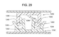
図28,29は、それぞれ非閉塞および閉塞位置で描かれた付加的実施例を示す。この実施例は、図26,27に開示された実施例とほぼ類似している。この実施例も同様に、雌封入要素1230のベース部分1234から延出するスプリング部材1244を含む。図29に最も分かりやすく図示されているように、二つの実施例の間の主な相違は、この実施例のガイドウィング1260,1262が主として雌封入要素1230の雌フック部分1240,1242に作用するように変形されていることである。雌フック部分1240,1242に作用することにより、雌フック部分は横方向以外の角度で雄フック部分1256,1258に押圧される。この特徴を実現するため、この実施例のガイドウィング1260,1262は、図26,27に開示された実施例のガイドウィング1160,1162と比較して、短いか、ウェブ1252,1254に近接するか、これらの組合せである。
Figures 28 and 29 show additional embodiments depicted in the unoccluded and occluded positions, respectively. This embodiment is substantially similar to the embodiment disclosed in FIGS. This embodiment also includes a
図30は概して、容器を画定するフィルム1304に対する雌および雄封入要素1330,1332の配置を示す。雌および雄封入要素1330,1332は、ベース部分1334,1350をそれぞれ含む。ベース部分1334,1350は、それぞれ雌および雄封入要素1330,1332をフィルム1304の同じ側へ装着する。これは、雌および雄封入要素1330,1332の一般的な構成である。この構成の結果、図1に図示された容器となる。本発明のある実施例では、図示された実施例と異なり、雌および雄封入要素1330,1332がフィルム1304に一体的に形成されることに言及すべきである。この構造では、フィルム1304と雌封入要素1330と雄封入要素1332とは一体的に単体を形成する。
FIG. 30 generally illustrates the placement of female and
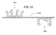
図31は、図30の構成の変形を示す。この実施例では、雌および雄封入要素1430,1432はフィルム1404の反対側に配置されている。この構造は、電線を電気絶縁するか電線の束を結束するのに使用できる。さらに、雌および雄封入要素1430,1432はシールされた封入部となるため、この構造はフレキシブルストローの形成にも使用できる。
FIG. 31 shows a modification of the configuration of FIG. In this embodiment, female and
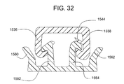
スプリング部材はウェブに設けられてもよい。図32を参照すると、スプリング部材1544はウェブ1538に設けられてウェブ1538から内側に延出している。この実施例では、スプリング部材1544はほぼ水平方向に、ウェブ1538に対してほぼ垂直に延在する。この実施例では、図32に見られるようにスプリング部材1544はフック部分1558と嵌合する。他の実施例では、スプリング部材はウェブに対して他の角度で延在し、ウェブから内側または外側に延出する。そのうえ、スプリング部材は、ウェブ1536,1552,1554などの他のウェブまたはガイドウィング1560,1562に設けられるか、これらの組合せであるか、ここに開示される他の実施例との組合せである。
The spring member may be provided on the web. Referring to FIG. 32, the
スプリング部材は、他の封入手段または締結ストリップに使用されてもよい。例えば、スプリング部材は、米国特許第3,806,998号に記載された「矢じりタイプ」または「リブ・溝」締結ストリップ、米国特許第5,664,299号に記載された「輪郭」締結ストリップ、米国特許第5,007,143号に記載された「ローリング動作」締結ストリップに使用されてもよい。 The spring member may be used for other enclosing means or fastening strips. For example, the spring member may be an “arrowhead type” or “rib-groove” fastening strip described in US Pat. No. 3,806,998, a “contour” fastening strip described in US Pat. No. 5,664,299. May be used in the “rolling motion” fastening strip described in US Pat. No. 5,007,143.
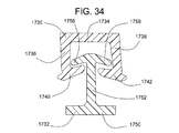
例えば、係合締結ストリップは、米国特許第3,806,998号および図34に図示された変形に記載された「矢じりタイプ」または「リブ・溝」締結ストリップを包含してもよい。図34を参照すると、雌締結ストリップ1736は、ベース1734とウェブ1736,1738とフック部分1740,1742とを含む。雄締結ストリップ1732は、ベース1750とウェブ1752とフック部分1756,1758とを含む。図34において、フック部分1740,1742,1756,1758が相互に接触しないように、締結ストリップ1732,1736は緩い。他の実施例では、締結ストリップは、米国特許第3,806,998号に記載された締結ストリップと一層類似した外観を持つ。
For example, the engagement fastening strip may include an “arrowhead type” or “rib-groove” fastening strip described in US Pat. No. 3,806,998 and the variations illustrated in FIG. Referring to FIG. 34,
図35を参照すると、締結ストリップはスプリング部材1844を含む。この実施例では、スプリング部材1844はベース1834に設けられてフック1858に作用する。スプリング部材1844によりフック部分は相互に接触して良好なシールとなる。他の実施例では、スプリング部材1844は、いずれかの締結ストリップか両方の締結ストリップに設けられる。また、他の実施例では、スプリング部材は、ウェブ1836,1838,1852またはベース1850など、他の箇所に設けられてもよい。
Referring to FIG. 35, the fastening strip includes a
封入手段は、使用目的に合わせて多様な形状で製造することができる。封入手段は、周知の方法のいずれかの使用により容器に接続される。例えば、熱電気手段が封入手段の雄および雌封入要素と接触状態でフィルムに形成されて、フィルムを介して熱を伝達し、フィルムと封入要素のベース部分との境界面に溶融を生じさせてもよい。適当な熱電気手段は、加熱回転ディスク、移動バンドヒータ、抵抗加熱スライドワイヤなどを含む。フィルムと雄および雌封入要素との間の接続を、ホットメルト接着剤、境界面への高温空気ジェット、超音波加熱、他の周知の方法の使用によって実現してもよい。フィルム材料への雄および雌封入要素の接合は、フィルムがU字形に畳まれてバッグを形成する前と後のいずれにおいて実施されてもよい。いずれにしても、このような接合は、従来の熱切断によるエッジにおけるバッグの側方シールに先立って行われる。雄および雌封入要素は通常、相互に対して略平行関係でフィルムに配置されるが、これは使用目的に左右される。 The sealing means can be manufactured in various shapes according to the purpose of use. The enclosing means is connected to the container by use of any known method. For example, thermoelectric means may be formed in the film in contact with the male and female encapsulation elements of the encapsulation means to transfer heat through the film and cause melting at the interface between the film and the base portion of the encapsulation element. Also good. Suitable thermoelectric means include heated rotating disks, moving band heaters, resistance heated slide wires, and the like. The connection between the film and the male and female encapsulation elements may be achieved by the use of hot melt adhesives, hot air jets to the interface, ultrasonic heating, or other well known methods. Joining of the male and female encapsulation elements to the film material may be performed either before or after the film is folded into a U shape to form a bag. In any case, such joining is performed prior to the side sealing of the bag at the edge by conventional thermal cutting. Male and female encapsulation elements are usually placed on the film in a substantially parallel relationship to each other, depending on the intended use.
図30,31に図示された構成が本発明の開示実施例すべてに適用されてもよいことに言及すべきである。 It should be noted that the configuration illustrated in FIGS. 30 and 31 may be applied to all disclosed embodiments of the present invention.
ここに引用された出版物と特許出願と特許とを含むすべての引例は、各引例が参考として取り入れられると個別かつ明確に指示され、その全体がここに提示されている場合と同じ程度、参考としてここに取り入れられる。 All references, including publications, patent applications and patents cited herein, are individually and clearly indicated as each reference is incorporated by reference, and to the same extent as if it were presented here in its entirety. As incorporated here.
本発明の記載内容(特に以下の請求項の内容)での“a”、“an”、“the”の語および同様の表記の使用は、他に指示されるか内容から明らかに矛盾しないかぎり、単数と複数の両方を含むものと解釈される。“comprising(包含する)”、“having(持つ)”、“including(含む)”、“containing(含有する)”の語は、他で指示されない限り、開放型の語(つまり“including, but not limited to(を含むがこれに限定されない)”として解釈される。ここでの数値の範囲の記載は、他に指示されない限り、範囲に含まれる各個別値を個々に言及する省略法であり、各個別値は、個別に記載されたかのように明細書に含まれるものとする。ここに記載されるすべての方法は、他に指示されないか、さもなければ内容から明らかに矛盾しないかぎり、適当な順序で実施することができる。ここに提示されるすべての例または例示的表現(例えば“such as(など)”)は、本発明をより明らかにするためのもので、他に主張されない限り本発明の範囲に限定を加えるものではない。明細書のいかなる表現も、本発明の実施に不可欠な非請求要素を示すものとして解釈されるべきである。 The use of the words “a”, “an”, “the” and similar notations in the context of the present invention, particularly the claims below, unless otherwise indicated or otherwise clearly contradicted by context. , As singular and plural. The terms “comprising”, “having”, “including”, “containing” are open words (ie, “including, but not” unless otherwise indicated). limited to "(including but not limited to). The recitation of numerical ranges herein is an abbreviation that individually refers to each individual value in the range, unless otherwise indicated, Each individual value shall be included in the specification as if it were individually listed, and all methods described herein are appropriate unless otherwise indicated or otherwise clearly contradicted by content. All examples or exemplary expressions presented here (eg “such as” etc.) are It is for the purpose of clarifying the invention and does not limit the scope of the invention unless otherwise claimed, and any representation in the specification indicates an unclaimed element essential to the practice of the invention. Should be interpreted as
本発明を実行するための発明者に周知の最適の態様を含めて、本発明の好適な実施例について記載した。これらの好適な実施例の変形は、以上の説明を読めば、当該技術の通常の技量を有するものには明らかになるだろう。発明者は、熟練技術者がこのような変形を適切なものとして採用すると予想し、発明者は明記された形以外で発明が実施されてもよいと考えている。したがって、適用法で認められているように、本発明は、添付の請求項に記載された主題の変形および均等物をすべて含む。さらに、他に指示されるか、さもなければ内容から明らかに矛盾しないかぎり、可能なあらゆる変形における上記要素の組合せは本発明に包含される。 Preferred embodiments of this invention have been described, including the best mode known to the inventors for carrying out the invention. Variations of these preferred embodiments will become apparent to those having ordinary skill in the art upon reading the foregoing description. The inventor expects skilled technicians to adopt such modifications as appropriate, and the inventor believes that the invention may be practiced in other ways than specified. Accordingly, as permitted by applicable law, the present invention includes all modifications and equivalents of the subject matter recited in the claims appended hereto. Moreover, any combination of the above-described elements in all possible variations thereof is encompassed by the invention unless otherwise indicated or otherwise clearly contradicted by content.
Claims (62)
長手方向に延在する雄封入要素であって、一部に延在する一対の雄フック部分を含み、該雄フック部分が反対向きである、雄封入要素と、
所定の長さにわたって雄封入要素と係合するのに適した、長手方向に延在する雌封入要素であって、一部に延在する一対の雌フック部分を含み、該雌フック部分が相互に近接するように延出し、該雌フック部分が、該封入手段が完全に閉塞された時に前記雄フック部分と嵌合および当接するのに適している、雌封入要素と、
前記封入要素の少なくとも一方に装着されて、前記封入手段が完全に閉塞された時に他の封入要素の前記フック部分の少なくとも一つへ荷重を印加するのに適している少なくとも一つのスプリング部材と、
を包含する封入手段。 A flexible resealable leak-proof container enclosing means defining an interior and an exterior,
A male enclosing element extending longitudinally, comprising a pair of male hook portions extending in part, the male hook portions being in opposite directions;
A longitudinally extending female encapsulation element suitable for engaging a male encapsulation element over a predetermined length, comprising a pair of female hook portions extending in part, the female hook portions being mutually A female encapsulation element that extends close to the female hook portion, the female hook portion being adapted to fit and abut against the male hook portion when the encapsulation means is fully occluded;
At least one spring member mounted on at least one of the encapsulation elements and adapted to apply a load to at least one of the hook portions of another encapsulation element when the encapsulation means is completely occluded;
Enclosing means.
第1および第2側壁を画定する肉薄フィルムと、
封入手段であって、さらに、所定の長さにわたって相互に係合するのに適した、長手方向に延在する雄および雌封入要素を包含する封入手段であり、該雄封入要素が、一部に延在する一対の雄フック部分を持ち、該雄フック部分が相互に反対向きであり、該雌封入要素が、一部に延在する一対の雌フック部分を持ち、該雌フック部分が相互に近接延出するとともに該封入手段が完全に閉塞された時に該雄フック部分と嵌合および当接することにより前記容器の内部と外部とを画定するのに適している、封入要素と、該封入手段が完全に閉塞された時に他の封入要素の該フック部分の少なくとも一つに荷重を印加するのに適した、いずれかの封入要素に装着される少なくとも一つのスプリング部材とを包含する封入手段と、
を包含する容器。 A flexible resealable leak-proof container defining an interior and an exterior,
A thin film defining first and second sidewalls;
An enclosure means, further comprising a longitudinally extending male and female enclosure element suitable for engaging with each other over a predetermined length, wherein the male enclosure element is partly A pair of male hook portions extending in the opposite directions, the male hook portions being opposite to each other, and the female enclosing element having a pair of female hook portions extending in part, the female hook portions being mutually An enclosing element suitable for defining an interior and an exterior of the container by fitting and abutting with the male hook portion when the enclosing means is fully closed An enclosing means comprising at least one spring member mounted on any enclosing element suitable for applying a load to at least one of the hook portions of the other enclosing element when the means is completely occluded When,
Containing container.
所定の長さにわたって雄封入要素と係合するのに適した、長手方向に延在する雌封入要素であって、一部に延在する一対の雌フック部分を含み、該雌フック部分が相互に近接延出する雌フック部分であって、該雌フック部分が、該封入手段が完全に閉塞された時に前記雄フック部分と嵌合および当接するのに適している、雌封入要素を設けることと、
前記封入要素の少なくとも一方に装着されて、前記封入手段が完全に閉塞された時に他の封入要素の前記フック部分の少なくとも一つへ荷重を印加するのに適している少なくとも一つのスプリング部材を設けることと、
を包含する、封入手段の製造方法。 Providing a male enclosing element extending in a longitudinal direction, the male enclosing element including a pair of male hook portions extending in part, the male hook portions being opposite to each other;
A longitudinally extending female encapsulation element suitable for engaging a male encapsulation element over a predetermined length, comprising a pair of female hook portions extending in part, the female hook portions being mutually A female hook portion extending proximate to the female hook portion, the female hook portion being adapted to fit and abut against the male hook portion when the sealing means is fully closed When,
At least one spring member is provided that is attached to at least one of the encapsulation elements and is suitable for applying a load to at least one of the hook portions of the other encapsulation element when the encapsulation means is completely occluded. And
A method of manufacturing the enclosing means.
長手方向に延在する雄封入要素であって、一部に延在する雄フック部分を含む雄封入要素と、
所定長さにわたって前記雄封入要素と係合するのに適した、長手方向に延在する雌封入要素であって、一部に延在する雌フック部分を含み、該雌フック部分が、前記封入手段が完全に閉塞された時に該雄フック部分と嵌合および当接するのに適した、雌封入要素と、
前記封入要素の少なくとも一方に装着されるとともに、前記封入手段が完全に閉塞された時に他の封入要素の前記フック部分に荷重を印加するのに適した少なくとも一つのスプリング部材と、
を包含する封入手段。 An enclosure means for a flexible resealable leak-proof container defining an interior and an exterior,
A male enclosing element extending longitudinally and including a male hook portion extending in part;
A longitudinally extending female encapsulation element suitable for engaging the male encapsulation element over a predetermined length, comprising a female hook portion extending in part, the female hook portion comprising the encapsulation A female enclosing element suitable for mating and abutting the male hook portion when the means is fully occluded;
At least one spring member attached to at least one of the enclosing elements and adapted to apply a load to the hook portion of another enclosing element when the enclosing means is completely occluded;
Enclosing means.
Applications Claiming Priority (2)
| Application Number | Priority Date | Filing Date | Title |
|---|---|---|---|
| US10/882,000 US7322747B2 (en) | 2004-06-29 | 2004-06-29 | Leak proof closure device with spring member |
| PCT/US2005/022310 WO2006012229A2 (en) | 2004-06-29 | 2005-06-23 | Leak proof closure device with spring member |
Publications (2)
| Publication Number | Publication Date |
|---|---|
| JP2008507301A true JP2008507301A (en) | 2008-03-13 |
| JP2008507301A5 JP2008507301A5 (en) | 2008-09-18 |
Family
ID=35505828
Family Applications (1)
| Application Number | Title | Priority Date | Filing Date |
|---|---|---|---|
| JP2007519292A Pending JP2008507301A (en) | 2004-06-29 | 2005-06-23 | Leakage prevention enclosing means comprising a spring member |
Country Status (14)
| Country | Link |
|---|---|
| US (1) | US7322747B2 (en) |
| EP (1) | EP1761438B1 (en) |
| JP (1) | JP2008507301A (en) |
| KR (1) | KR20070038983A (en) |
| CN (1) | CN101426690B (en) |
| AU (1) | AU2005267292B2 (en) |
| CA (1) | CA2571211A1 (en) |
| DE (1) | DE602005027069D1 (en) |
| ES (1) | ES2362283T3 (en) |
| HK (1) | HK1130232A1 (en) |
| MX (1) | MXPA06015078A (en) |
| NZ (1) | NZ552123A (en) |
| WO (1) | WO2006012229A2 (en) |
| ZA (1) | ZA200610499B (en) |
Cited By (1)
| Publication number | Priority date | Publication date | Assignee | Title |
|---|---|---|---|---|
| JP2013014354A (en) * | 2011-07-01 | 2013-01-24 | Kureha Corp | Zipper and zipper bag |
Families Citing this family (29)
| Publication number | Priority date | Publication date | Assignee | Title |
|---|---|---|---|---|
| US7159282B2 (en) * | 2002-03-01 | 2007-01-09 | Pactiv Corporation | Reclosable fasteners or zippers for use with polymeric bags |
| US7437805B2 (en) * | 2006-06-23 | 2008-10-21 | Edward Alan Berich | Reclosable storage bag closure with internal valving |
| US7857514B2 (en) | 2006-12-12 | 2010-12-28 | Reynolds Foil Inc. | Resealable closures, polymeric packages and systems and methods relating thereto |
| US7784160B2 (en) | 2007-03-16 | 2010-08-31 | S.C. Johnson & Son, Inc. | Pouch and airtight resealable closure mechanism therefor |
| US7886412B2 (en) | 2007-03-16 | 2011-02-15 | S.C. Johnson Home Storage, Inc. | Pouch and airtight resealable closure mechanism therefor |
| US7857515B2 (en) | 2007-06-15 | 2010-12-28 | S.C. Johnson Home Storage, Inc. | Airtight closure mechanism for a reclosable pouch |
| US7967509B2 (en) | 2007-06-15 | 2011-06-28 | S.C. Johnson & Son, Inc. | Pouch with a valve |
| US7887238B2 (en) | 2007-06-15 | 2011-02-15 | S.C. Johnson Home Storage, Inc. | Flow channels for a pouch |
| US7874731B2 (en) | 2007-06-15 | 2011-01-25 | S.C. Johnson Home Storage, Inc. | Valve for a recloseable container |
| US7946766B2 (en) | 2007-06-15 | 2011-05-24 | S.C. Johnson & Son, Inc. | Offset closure mechanism for a reclosable pouch |
| US8061898B2 (en) * | 2008-07-15 | 2011-11-22 | S.C. Johnson & Son, Inc. | Venting closure mechanism |
| US20100297323A1 (en) * | 2008-10-14 | 2010-11-25 | Solazyme, Inc. | Gluten-free Foods Containing Microalgae |
| US8215839B2 (en) * | 2009-06-02 | 2012-07-10 | The Glad Products Company | Multistep occluding zipper with sealing features |
| US8272107B2 (en) * | 2009-10-28 | 2012-09-25 | S.C. Johnson & Son, Inc. | Vacuum-actuated closure mechanism for a resealable pouch |
| US8550716B2 (en) | 2010-06-22 | 2013-10-08 | S.C. Johnson & Son, Inc. | Tactile enhancement mechanism for a closure mechanism |
| US8087826B1 (en) | 2010-06-25 | 2012-01-03 | Pactiv Corporation | Slider track with improved seal strength |
| US9327875B2 (en) | 2010-10-29 | 2016-05-03 | S.C. Johnson & Son, Inc. | Reclosable bag having a loud sound during closing |
| US8469593B2 (en) | 2011-02-22 | 2013-06-25 | S.C. Johnson & Son, Inc. | Reclosable bag having a press-to-vent zipper |
| US8568031B2 (en) | 2011-02-22 | 2013-10-29 | S.C. Johnson & Son, Inc. | Clicking closure device for a reclosable pouch |
| CN105966737B (en) | 2012-02-03 | 2023-09-08 | 凸版印刷株式会社 | Bag and bag sealed with contents |
| CN102602580B (en) * | 2012-03-01 | 2015-04-29 | 上海鸿研物流技术有限公司 | Connector and transfer container with same |
| FR2988701B1 (en) * | 2012-04-03 | 2014-04-11 | S2F Flexico | CLOSURE DEVICE FOR SACHETS OR EQUIVALENTS HAVING IMPROVED TOUCH AND SOUND EFFECT, SACHET THUS OBTAINED AND METHOD OF MAKING SAME |
| US20130287322A1 (en) * | 2012-04-27 | 2013-10-31 | Lifeng Gong | Leak-proof slider assembly |
| US20130299512A1 (en) * | 2012-05-14 | 2013-11-14 | Naira Gevorkian | Collapsible dispensing tube with internal press-to-close sealers to prevent reverse flow of the content towards the closed end |
| US9133598B2 (en) | 2013-01-17 | 2015-09-15 | Polymics, Ltd. | Sealed interconnected mat system |
| JP6379003B2 (en) * | 2014-10-09 | 2018-08-22 | 株式会社タキガワ・コーポレーション・ジャパン | Chuck with child resistance function and packaging bag with chuck |
| CN105625833B (en) * | 2014-10-27 | 2021-03-16 | 因特瓦产品有限责任公司 | Mechanical seal between actuator housing and cover and method of providing a seal between actuator housing and cover |
| US9790002B2 (en) | 2015-01-29 | 2017-10-17 | Inteplast Group Corporation | Bag with gripping panels |
| US9624003B1 (en) | 2015-11-24 | 2017-04-18 | Inteplast Group Corporation | Bag with gripping bands |
Citations (3)
| Publication number | Priority date | Publication date | Assignee | Title |
|---|---|---|---|---|
| JPS6423956A (en) * | 1987-06-22 | 1989-01-26 | First Brands Corp | Interlock sealing device |
| JPH04294747A (en) * | 1991-03-22 | 1992-10-19 | Seisan Nipponsha Kk | Synthetic resin-made fastener |
| JPH08324595A (en) * | 1995-05-30 | 1996-12-10 | Showa Highpolymer Co Ltd | Plastic fastener |
Family Cites Families (20)
| Publication number | Priority date | Publication date | Assignee | Title |
|---|---|---|---|---|
| FR2126060B1 (en) | 1971-02-22 | 1974-06-21 | Flexico France Sarl | |
| US4362198A (en) * | 1978-03-31 | 1982-12-07 | Union Carbide Corporation | Closure device |
| US4778282A (en) | 1985-09-11 | 1988-10-18 | First Brands Corporation | Trident interlocking closure profile configuration |
| US4710968A (en) | 1985-09-11 | 1987-12-01 | First Brands Corporation | Trident interlocking closure profile configuration |
| US4854017A (en) * | 1986-07-22 | 1989-08-08 | First Brands Corporation | Multiposition interlocking closure fastening device |
| US4907321A (en) * | 1987-06-22 | 1990-03-13 | First Brands Corporation | Enhanced color change interlocking closure strip |
| US5067822A (en) * | 1989-04-24 | 1991-11-26 | Reynolds Consumer Products, Inc. | Method of forming recloseable packages, profiles used therein, and packages produced thereby |
| US5007143A (en) | 1990-03-07 | 1991-04-16 | Mobil Oil Corp. | Rolling action zipper profile and slipper therefor |
| US5192135A (en) * | 1991-05-31 | 1993-03-09 | Dowbrands L.P. | Profile and adjacent rib-type closure element for reclosable thermoplastic bags |
| US5248201A (en) | 1992-02-24 | 1993-09-28 | Reynolds Consumer Products Inc. | Interlocking closure for plastic storage bags with confirming color strips |
| JPH0576310U (en) * | 1992-03-30 | 1993-10-19 | 吉田工業株式会社 | Airtight bite fastener |
| US5509734A (en) * | 1994-01-11 | 1996-04-23 | Minigrip, Inc. | Wedge activated zipper |
| US5664299A (en) | 1996-09-10 | 1997-09-09 | Dowbrands L.P. | Reclosable fastener assembly |
| US6045264A (en) * | 1998-01-29 | 2000-04-04 | Miniea; Stephen H. | Self-sealing, disposable storage bag |
| US6074096A (en) * | 1998-02-03 | 2000-06-13 | Reynolds Consumer Products, Inc. | Closure arrangement having improved thermal stability and methods thereof |
| FR2780037B1 (en) * | 1998-06-17 | 2000-09-08 | Flexico France Sarl | BAG COMPRISING ADDITIONAL CLOSING CLOSURE PROFILES |
| US6167597B1 (en) | 1998-07-13 | 2001-01-02 | Illinois Tool Works, Inc. | High compression zipper |
| US6009603A (en) * | 1998-10-29 | 2000-01-04 | Gallagher; Stephen F. | Closure fastener strips for resealable plastic film pouches |
| US7234865B2 (en) * | 2002-05-22 | 2007-06-26 | Illinois Tool Works Inc. | Closure for a reclosable package |
| US6854886B2 (en) * | 2002-06-28 | 2005-02-15 | Illinois Tool Works Inc. | Watertight closure for a reclosable package |
-
2004
- 2004-06-29 US US10/882,000 patent/US7322747B2/en not_active Expired - Fee Related
-
2005
- 2005-06-23 AU AU2005267292A patent/AU2005267292B2/en not_active Ceased
- 2005-06-23 NZ NZ552123A patent/NZ552123A/en not_active IP Right Cessation
- 2005-06-23 EP EP05763162A patent/EP1761438B1/en not_active Expired - Fee Related
- 2005-06-23 CN CN2005800218388A patent/CN101426690B/en not_active Expired - Fee Related
- 2005-06-23 KR KR1020067027623A patent/KR20070038983A/en not_active Application Discontinuation
- 2005-06-23 WO PCT/US2005/022310 patent/WO2006012229A2/en not_active Application Discontinuation
- 2005-06-23 MX MXPA06015078A patent/MXPA06015078A/en active IP Right Grant
- 2005-06-23 ES ES05763162T patent/ES2362283T3/en active Active
- 2005-06-23 JP JP2007519292A patent/JP2008507301A/en active Pending
- 2005-06-23 CA CA002571211A patent/CA2571211A1/en not_active Abandoned
- 2005-06-23 DE DE602005027069T patent/DE602005027069D1/en active Active
-
2006
- 2006-12-14 ZA ZA200610499A patent/ZA200610499B/en unknown
-
2009
- 2009-09-04 HK HK09108099.4A patent/HK1130232A1/en not_active IP Right Cessation
Patent Citations (3)
| Publication number | Priority date | Publication date | Assignee | Title |
|---|---|---|---|---|
| JPS6423956A (en) * | 1987-06-22 | 1989-01-26 | First Brands Corp | Interlock sealing device |
| JPH04294747A (en) * | 1991-03-22 | 1992-10-19 | Seisan Nipponsha Kk | Synthetic resin-made fastener |
| JPH08324595A (en) * | 1995-05-30 | 1996-12-10 | Showa Highpolymer Co Ltd | Plastic fastener |
Cited By (1)
| Publication number | Priority date | Publication date | Assignee | Title |
|---|---|---|---|---|
| JP2013014354A (en) * | 2011-07-01 | 2013-01-24 | Kureha Corp | Zipper and zipper bag |
Also Published As
| Publication number | Publication date |
|---|---|
| CA2571211A1 (en) | 2006-02-02 |
| ZA200610499B (en) | 2008-07-30 |
| EP1761438A4 (en) | 2009-05-06 |
| NZ552123A (en) | 2010-11-26 |
| US7322747B2 (en) | 2008-01-29 |
| ES2362283T3 (en) | 2011-06-30 |
| WO2006012229A3 (en) | 2009-02-05 |
| AU2005267292B2 (en) | 2011-09-15 |
| EP1761438B1 (en) | 2011-03-23 |
| US20050286813A1 (en) | 2005-12-29 |
| HK1130232A1 (en) | 2009-12-24 |
| EP1761438A2 (en) | 2007-03-14 |
| WO2006012229A2 (en) | 2006-02-02 |
| CN101426690A (en) | 2009-05-06 |
| MXPA06015078A (en) | 2007-03-01 |
| DE602005027069D1 (en) | 2011-05-05 |
| AU2005267292A1 (en) | 2006-02-02 |
| CN101426690B (en) | 2011-01-12 |
| KR20070038983A (en) | 2007-04-11 |
Similar Documents
| Publication | Publication Date | Title |
|---|---|---|
| JP2008507301A (en) | Leakage prevention enclosing means comprising a spring member | |
| US4212337A (en) | Closure fastening device | |
| JP3236301B2 (en) | Fasteners for bags | |
| JP5996172B2 (en) | Tamper-evident packaging bag | |
| JP4559615B2 (en) | Plastic chuck with slider for preventing unauthorized opening and bag body with chuck | |
| JP4764599B2 (en) | Plastic chuck with slider and bag with plastic chuck | |
| JP2007534446A (en) | Ventable interlocking closure strip | |
| JPH05501098A (en) | Improved closure for reclosable thermoplastic containers | |
| WO2013180750A1 (en) | Flip-lock instant closure mechanism and method | |
| US11338962B2 (en) | Bag container with sealing mechanism | |
| US6874205B1 (en) | Closure device | |
| JP2007119043A (en) | Zipper for bag and packaging bag fixed with this zipper | |
| JP4327090B2 (en) | Multi-part closure device | |
| US4362198A (en) | Closure device | |
| US6611998B1 (en) | Closure device | |
| US6611997B1 (en) | Closure device | |
| JP2009131369A (en) | Synthetic resin zipper tape | |
| JP4010746B2 (en) | Glass bonding bag | |
| JP7020997B2 (en) | Bag with fitting | |
| JP4176822B1 (en) | Sealed bag | |
| JPH018521Y2 (en) | ||
| CA1118392A (en) | Closure fastening device | |
| WO2013108632A1 (en) | Slider, slider zipper tape, and packaging bag with slider | |
| JP2527618Y2 (en) | Package clip | |
| JP2014117289A (en) | Zip fastener, packaging material, and package |
Legal Events
| Date | Code | Title | Description |
|---|---|---|---|
| RD04 | Notification of resignation of power of attorney |
Free format text: JAPANESE INTERMEDIATE CODE: A7424 Effective date: 20080331 |
|
| A521 | Written amendment |
Free format text: JAPANESE INTERMEDIATE CODE: A523 Effective date: 20080620 |
|
| A621 | Written request for application examination |
Free format text: JAPANESE INTERMEDIATE CODE: A621 Effective date: 20080620 |
|
| A977 | Report on retrieval |
Free format text: JAPANESE INTERMEDIATE CODE: A971007 Effective date: 20101014 |
|
| A131 | Notification of reasons for refusal |
Free format text: JAPANESE INTERMEDIATE CODE: A131 Effective date: 20101019 |
|
| A02 | Decision of refusal |
Free format text: JAPANESE INTERMEDIATE CODE: A02 Effective date: 20110322 |