JP2008506308A - Extended dynamic range imaging system - Google Patents
Extended dynamic range imaging system Download PDFInfo
- Publication number
- JP2008506308A JP2008506308A JP2007520306A JP2007520306A JP2008506308A JP 2008506308 A JP2008506308 A JP 2008506308A JP 2007520306 A JP2007520306 A JP 2007520306A JP 2007520306 A JP2007520306 A JP 2007520306A JP 2008506308 A JP2008506308 A JP 2008506308A
- Authority
- JP
- Japan
- Prior art keywords
- paxels
- saturated
- integration time
- paxel
- image
- Prior art date
- Legal status (The legal status is an assumption and is not a legal conclusion. Google has not performed a legal analysis and makes no representation as to the accuracy of the status listed.)
- Pending
Links
Images


Classifications
-
- H—ELECTRICITY
- H04—ELECTRIC COMMUNICATION TECHNIQUE
- H04N—PICTORIAL COMMUNICATION, e.g. TELEVISION
- H04N25/00—Circuitry of solid-state image sensors [SSIS]; Control thereof
- H04N25/50—Control of the SSIS exposure
- H04N25/57—Control of the dynamic range
-
- H—ELECTRICITY
- H04—ELECTRIC COMMUNICATION TECHNIQUE
- H04N—PICTORIAL COMMUNICATION, e.g. TELEVISION
- H04N23/00—Cameras or camera modules comprising electronic image sensors; Control thereof
-
- H—ELECTRICITY
- H04—ELECTRIC COMMUNICATION TECHNIQUE
- H04N—PICTORIAL COMMUNICATION, e.g. TELEVISION
- H04N23/00—Cameras or camera modules comprising electronic image sensors; Control thereof
- H04N23/70—Circuitry for compensating brightness variation in the scene
- H04N23/71—Circuitry for evaluating the brightness variation
-
- H—ELECTRICITY
- H04—ELECTRIC COMMUNICATION TECHNIQUE
- H04N—PICTORIAL COMMUNICATION, e.g. TELEVISION
- H04N25/00—Circuitry of solid-state image sensors [SSIS]; Control thereof
- H04N25/50—Control of the SSIS exposure
- H04N25/53—Control of the integration time
- H04N25/533—Control of the integration time by using differing integration times for different sensor regions
-
- H—ELECTRICITY
- H04—ELECTRIC COMMUNICATION TECHNIQUE
- H04N—PICTORIAL COMMUNICATION, e.g. TELEVISION
- H04N25/00—Circuitry of solid-state image sensors [SSIS]; Control thereof
- H04N25/60—Noise processing, e.g. detecting, correcting, reducing or removing noise
Abstract
撮像装置内で飽和パクセルの積分時間を減少させる方法であって、当該方法は、捕捉画像からの場面データに従って撮像装置内で前記飽和パクセルの積分時間を減少させるステップを有する。
A method for reducing the integration time of a saturated paxel in an imaging device, the method comprising reducing the integration time of the saturated paxel in the imaging device according to scene data from a captured image.
Description
本発明は、概して、画像化の分野、具体的には、プログラム可能な積分時間に基づく、画素アドレスを備える電子撮像装置による画像化に関する。 The present invention relates generally to the field of imaging, and in particular to imaging with electronic imaging devices with pixel addresses based on programmable integration times.
撮像装置、特に、CMOS撮像装置には、従来、場面の一部がその中に強調表示を有する程に高いダイナミックレンジを有する場面に関する問題がある。これは、場面露出寛容度と呼ばれる。画像のこれらの強調表示された部分において、センサの画素は、デジタル画素出力が全て1であるように飽和する。従って、センサの画素は、捕捉された場面が、例えば、公園で太陽に背を向けて立っているカップルといった、通常捕捉され得るよりも広いダイナミックレンジを含む場合に、特に飽和する。通常の場面は、6から7絞り(stops)のダイナミックレンジを有することができる。太陽の画像は、ダイナミックレンジの他の10絞りを導入する。当該技術分野のカメラの現状は、カップルを捕捉するための露出レベルを設定し、太陽が、結果として得られる像において画像を飽和させることを許容する。似たような状況は、例えば、金属の車のバンパーに反射する太陽といった、正反射を含む画像に存在する。捕捉すべき1つの他の例となる厄介な場面は、夜の駐車場における車を含む。車を正確に露光させる結果、車のヘッドライト及び駐車場を照らす街灯は、結局のところ画像を飽和させうる。結果として、従来の撮像システムに関して、露出を決定する際の非常に僅かなエラーは、場面のダイナミックレンジが画像捕捉システムのダイナミックレンジに近い又は等しい場合に許容されうる。 Imaging devices, particularly CMOS imaging devices, have traditionally had problems with scenes having a dynamic range that is so high that some of the scenes have highlights therein. This is called scene exposure tolerance. In these highlighted portions of the image, the sensor pixels saturate so that the digital pixel output is all ones. Thus, sensor pixels are particularly saturated when the captured scene includes a wider dynamic range than can normally be captured, such as a couple standing back to the sun in a park. A normal scene can have a dynamic range of 6 to 7 stops. The sun image introduces another 10 stops of dynamic range. The current state of the art camera sets the exposure level to capture the couple and allows the sun to saturate the image in the resulting image. A similar situation exists in images that contain specular reflections, such as the sun reflecting off a metal car bumper. One other example messy scene to be captured includes a car in a night parking lot. As a result of accurately exposing the car, the streetlights that illuminate the car headlights and parking can eventually saturate the image. As a result, with respect to conventional imaging systems, very slight errors in determining exposure can be tolerated when the dynamic range of the scene is close to or equal to the dynamic range of the image capture system.
必要とされるものは、捕捉された場面よりも大きなダイナミックレンジを常に有する画像捕捉システムである。 What is needed is an image capture system that always has a larger dynamic range than the captured scene.
前出の必要物は、撮像装置内で飽和パクセルの積分時間を減少させる方法であって、捕捉画像からの場面データに従って撮像装置内で前記飽和パクセルの積分時間を減少させるステップを有する方法を提供することにより、本発明によって扱われる。本発明の他の態様は、パクセルの独立した積分時間制御と、前記パクセルの正確な積分時間をそれらの飽和レベルに基づいて決定するためのアルゴリズムとを可能にする撮像装置を有する電子画像捕捉システムを備える。 What is needed is a method for reducing the integration time of a saturated paxel in an imaging device, the method comprising the step of reducing the integration time of the saturated paxel in the imaging device according to scene data from a captured image To be addressed by the present invention. Another aspect of the present invention is an electronic image capture system having an imaging device that enables independent integration time control of the paxels and an algorithm for determining the exact integration time of the paxels based on their saturation levels. Is provided.
複数の画像捕捉を通して、パクセルの積分時間は、場面のダイナミックレンジと、捕捉された場面の信号対雑音比との間の理想的な妥協に達するよう調整される。 Through multiple image captures, the paxel integration time is adjusted to reach an ideal compromise between the dynamic range of the scene and the signal-to-noise ratio of the captured scene.
本発明は、挙げられている問題を正し、より大きな場面露出寛容度を有するシステムをもたらしうる。従って、本発明は、一層大きな場面ダイナミックレンジを捕捉する能力を有する画像捕捉システムをもたらしうる。 The present invention corrects the listed problems and can result in a system with greater scene exposure latitude. Thus, the present invention can provide an image capture system that has the ability to capture a larger scene dynamic range.
以下の記載で、本発明は、制御装置としてマイクロプロセッサを用い、また、パクセル積分時間アルゴリズムを実行する好ましい実施例において説明される。当業者には明らかなように、このシステムの等価なものは、また、ハードウェアのみで構成されても良い。 In the following description, the present invention will be described in a preferred embodiment using a microprocessor as the controller and implementing a paxel integration time algorithm. As will be apparent to those skilled in the art, the equivalent of this system may also consist of hardware only.
本発明は、画像の明るい又は強調表示された領域の地理的位置を決定する。本発明によって用いられる適応性露出アルゴリズムは、画像の強調表示領域におけるパクセルの積分時間を、これらのパクセルが正確に、即ち、飽和近くに、しかし飽和しないよう露光されるように、減少させる。このようにして、従来の方法を用いて捕捉されうるよりも広いダイナミックレンジを有する場面を捕捉することが可能となる。更なるダイナミックレンジは、減少した積分時間を有するパクセルによって捕捉されたダイナミックレンジである。本発明は、Robert M.Guidashの名において2003年9月3日に出願された米国特許整理番号10/654,313に更に詳細に説明され、且つ、本願に援用されているような、互いに独立に撮像装置内でパクセルの積分時間をプログラミングする能力を活用する。 The present invention determines the geographic location of bright or highlighted areas of the image. The adaptive exposure algorithm used by the present invention reduces the integration time of the paxels in the highlighted region of the image so that these paxels are exposed accurately, ie close to saturation but not saturated. In this way, it is possible to capture a scene having a wider dynamic range than can be captured using conventional methods. A further dynamic range is the dynamic range captured by the paxel with a reduced integration time. The present invention relates to Robert M. et al. In the name of Guidash, paxel's in an imaging device independently of each other as described in more detail in US patent application Ser. No. 10 / 654,313 filed Sep. 3, 2003 and incorporated herein by reference. Take advantage of the ability to program the integration time.
ダイナミックレンジの問題を解決するために、実施例では、本発明は、個々の画素レベルを有効にするCMOS撮像センサを用いて、画素のX−Yアドレスに基づいて積分時間のプログラミングを行う。1度の露出で、積分時間を変更するとともに画素の交互に並んだ行を有することが可能である。また、小さなX−Yグループで画素をグループ化することも可能である。このような小さなX−Yグループは、パクセルと呼ばれる。これらのパクセルのX−Yサイズは、動的に変化しうる。通常、これらのパクセルは、画像において異なる色を検出するために使用されるカラーフィルタアレイパターンに基づく。例えば、ベイヤーカラーフィルタアレイパターン(CFA)は、最初のラインで交互に並ぶ緑−赤を有し、次のラインで交互に並ぶ青−緑を有する。このCFAフィルタは、撮像装置内の全てのラインに関して繰り返される。著しく異なる積分時間を有する撮像装置の交互に並んだ行が設定されても良い。本発明は、画素のブロック、即ち、同様に、パクセルを利用する。幾つかのブロックは、長い積分時間を有しても良く、また、幾つかは、短い積分時間を有しても良い。 In order to solve the problem of dynamic range, in an embodiment, the present invention uses an CMOS image sensor that enables individual pixel levels to program integration time based on the XY address of the pixel. With a single exposure, it is possible to change the integration time and have alternating rows of pixels. It is also possible to group pixels by small XY groups. Such a small XY group is called a paxel. The XY size of these paxels can change dynamically. Typically, these paxels are based on a color filter array pattern that is used to detect different colors in the image. For example, the Bayer color filter array pattern (CFA) has green-red alternating in the first line and blue-green alternating in the next line. This CFA filter is repeated for all lines in the imaging device. Alternate rows of imaging devices having significantly different integration times may be set. The present invention utilizes a block of pixels, ie, paxels as well. Some blocks may have a long integration time, and some may have a short integration time.
本発明の一実施例では、撮像装置により捕捉された場面データは、画素ごとに基づいて、飽和に関して解析及び評価をなされる。撮像装置は、個々のX−Yアドレス指定可能な積分時間を有する撮像装置である。ここで、積分時間は、撮像装置が捕捉過程の間に画像を取り込むことができる時間の量として決定される。本発明に関しては、飽和パクセルのみの積分時間が減少する。更なる画像は、飽和パクセルがほぼ零となるまで、異なる積分時間の下、繰り返し、捕捉、解析及び評価をなされる。 In one embodiment of the present invention, scene data captured by the imaging device is analyzed and evaluated for saturation on a pixel-by-pixel basis. The imaging device is an imaging device having an integration time that can be addressed individually by XY. Here, the integration time is determined as the amount of time that the imaging device can capture an image during the capture process. For the present invention, the integration time of only saturated paxels is reduced. Further images are iterated, captured, analyzed and evaluated under different integration times until the saturated paxels are nearly zero.
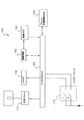
図1を参照すると、本発明の一実施例は、マイクロプロセッサ120によって制御される光学フラッシュ110を有するカメラシステム100を示す。マイクロプロセッサ120は、また、シャッター130と、撮像装置140と、画像メモリ150と、フラッシュ不揮発性メモリ160とを制御する。2段階、2接触シャッター・リリース・スイッチ170は、信号をマイクロプロセッサ120へ入力する。当業者には明らかなように、本発明は、また、1段階、1接触シャッター・リリース・スイッチ170を用いても実施可能である。
Referring to FIG. 1, one embodiment of the present invention shows a
マイクロプロセッサ120は、カメラシステム100向けのマイクロプロセッサ120の既知の機能に加えて、撮像装置140と画像メモリ150との間の関係を制御する、図3に示されるパクセル積分時間アルゴリズムを実行する。一般に、画像は、撮像装置140から画像メモリ150へと捕捉され、図3で示されるパクセル積分時間アルゴリズムは、最終の画像において夫々のパクセルの正確な積分時間を決定する。
撮像装置140は、パクセルとして知られる画素のグループの独立したX−Yアドレス指定可能な積分時間を有するCMOS撮像装置又はCCD撮像装置でありうる。ここに記載されている実施例では、フラッシュ不揮発性メモリ160が使用されているが、当業者には明らかなように、EPROM、バッテリー支援RAM及びヒュージブルリンクROMは、本発明による使用の代わりに用いられ得る幾つかの他のメモリ選択肢である。
The
第2の実施例は、図2に示される電子撮像システム200を用いる(このシステムは、電子静止カメラ、モーション・キャプチャシステム、若しくはマシンビジョンシステム、又は撮像機能を用いる如何なる装置であっても良い。)。図2は、カメラシステム200が、パクセルのプログラム可能な積分機能を有するCMOS撮像装置240を有することを表す。CMOS撮像装置240は、また、複数の並列なデータ信号出力290を有する。これらの複数の並列なデータ信号出力290は、CMOS撮像装置240の読取レートを向上させる。結果として、最終の像までの時間は減少する。他の全ての点で、動作は、図1に示された第1の実施例と同じである。
The second embodiment uses the
図3を参照すると、パクセル積分時間アルゴリズム300は、捕捉画像からの場面データに従って撮像装置内で飽和パクセルの積分時間を減少させるために示される。図1及び図2で示されるシャッター・リリース・スイッチ170を動作させるためのシャッター動作310は、カメラシステム100及び200の全体的な露出を決定するために使用される。画像捕捉動作320で、第1の画像は、(図1又は図2のいずれか一方に従って)メモリ150又は250へと捕捉される。夫々のパクセルは、動作330で飽和を検査される。全てのパクセル値は、夫々のパクセルを構成する4つの画素を1つの値に平均化することによって導出される。その値が最大値(K)に等しい又はそれより大きいならば、対応するパクセルは、飽和しているとみなされる。動作330が完了すると、飽和パクセルのX−Y位置は、動作340で記録される。その後、飽和パクセルは、動作350で合計される。条件付き動作360は、飽和パクセルの個数が0であるならば、画像が動作365で不揮発性フラッシュメモリへ書き込まれることを決定する。代替的に、条件付き動作360に関して、飽和パクセルの個数が0ではないならば、飽和パクセルの個数は、動作370で数えられる。随意的な条件付き動作362は、2段階シャッター・リリース・スイッチ170又は270がカメラ100又は200に対して夫々使用される場合に、条件付き動作360と書き込み動作365との間に組み入れられる。
Referring to FIG. 3, a paxel
第2の条件付き動作である動作375は、飽和パクセルの個数が定数Nよりも大きいかどうかを決定する。動作385において、飽和パクセルの積分時間は、大きなインクリメント(本例では、1/4の露出時間又は2絞り)だけ減少させられる。1絞りは、信号の半減又は2倍の低減である。2絞りは、信号における4倍の低減である。大きなインクリメントは、全体的なダイナックレンジがより大きい正確に露光された画像を得るために必要とされる捕捉の数を減らすために使用される(積分時間における大幅な低減は、正確な積分時間が実現されるまで使用される。その場合に、積分時間におけるより小さなインクリメント低減は、より高い精度のために使用される。)。飽和パクセルの個数が動作380で定数Nよりも小さいならば、飽和パクセルの積分時間は、より少ないインクリメント(本例では、1/2の露出時間又は1絞り)だけ減少する。
A second conditional operation,
動作390は、動作350で使用されたパクセルカウンタをリセットする。動作395は、パクセルの積分時間を記録する。新しい画像は、動作320で捕捉され、アルゴリズムは、「0個の飽和パクセル」という規準が動作360で満たされるまで繰り返される。拡張されたダイナミックレンジの画像は、その場合に、動作365で、それらの夫々のパクセルに関連する積分時間と、パクセルのX−Y位置とともに記録される。この情報は、たとえ次の捕捉の間であっても、画像再構成過程で使用される。
飽和パクセルの個数が定数Nに等しい又はそれよりも小さく、且つ、定数Mよりも大きいならば、飽和パクセルの積分時間は、小さいインクリメント(本例では、3/4の露出時間又は1/2の絞り)だけ減少する。小さいインクリメントは、システムが、露光されすぎたパクセルを大幅に露出不足としないように使用される。飽和パクセルが定数Mに等しい又はそれよりも小さいならば、露出は正確であるとみなされ、画像は捕捉される。 If the number of saturated paxels is equal to or less than the constant N and greater than the constant M, the integration time of the saturated paxels is reduced by a small increment (in this example 3/4 exposure time or 1/2 Aperture) decreases. Small increments are used so that the system does not significantly underexpose the overexposed paxels. If the saturated paxel is equal to or less than the constant M, the exposure is considered accurate and the image is captured.
どちらの積分時間も、これが、下流の画像再構成アルゴリズムのために必要とされる情報であるので、記録される。その前提は、飽和パクセルの個数が多くなればなるほど、画像はますます飽和することである。第2の画像は捕捉され、処理は繰り返される。これは、飽和パクセルが存在しなくなるまで続く。像メモリに記憶された画像は、目下、フラッシュメモリへ書き込まれている。二重の積分時間選択は、システムが、より少ない回数の画像捕捉で正確な全体露出に達することを可能にする。この方法は、飽和パクセルの積分時間において複数の変更個所を伴って複数の決定点へと拡張され得る。 Both integration times are recorded because this is the information needed for the downstream image reconstruction algorithm. The premise is that the more saturated paxels, the more saturated the image. The second image is captured and the process is repeated. This continues until there are no saturated paxels. The image stored in the image memory is currently written to the flash memory. Double integration time selection allows the system to reach an accurate overall exposure with fewer image captures. This method can be extended to multiple decision points with multiple changes in the saturation paxel integration time.
画素を単一の値へと平均化することにより、夫々のパクセルが導出される(例えば、2×2パクセルがある。しかし、パクセルサイズは変更可能である。)。図4及びパクセルダイアグラム400を参照すると、幾つかのパクセル配列が示されている。例えば、2×2多色パクセル420及び4×4多色パクセル430がある。また、2×2緑色パクセル440、2×2赤色パクセル450、2×2青色パクセル460、及び4×4緑色パクセル470が示されている。撮像装置による実施のためにベイヤーカラーフィルタアレイパターンとともに使用されるパクセル410も示されている。
Each pixel is derived by averaging the pixels to a single value (eg, there are 2 × 2 pixels, but the pixel size can be changed). Referring to FIG. 4 and paxel diagram 400, several paxel arrangements are shown. For example, there are 2 × 2
本発明の代わりの実施例を検討する。例えば、一実施例では、電子撮像システムは、連続的に動作しており、パクセルのプログラム可能な積分機能を有するCMOS撮像装置240を含む。電子撮像システム200は、連続的に動作する。シャッター・リリース・ボタンが押されると、最初の0飽和パクセル画像が記憶される。像捕捉までの時間は減少する。他の全ての点で、それは、先に述べた実施例と同様に動作する。
Consider an alternative embodiment of the present invention. For example, in one embodiment, the electronic imaging system includes a
他の実施例は、2段階シャッター・リリース・スイッチを使用する電子静止カメラ撮像システム200である。第1のスイッチが閉じられると、カメラが動作し始める。本発明は、通常の飽和パクセルに関して正確な積分時間を求める。第2のスイッチが閉じられると、飽和画像を含まない第1の画像は、不揮発性フラッシュメモリ260に記憶される。本発明は、パクセルのプログラム可能な積分機能を有するCMOS撮像装置240を有する。像捕捉までの時間は減少する。
Another embodiment is an electronic still
更なる他の実施例は、パクセルのプログラム可能な積分機能を有するCMOS撮像装置240を有する撮像システム10である。このシステムは、前出の実施例に含まれている考えの幾つか又は全てを使用する。本実施例の第1の目的は、カメラ露出決定システムのためのセンサを形成することである。それは、フィルムカメラ又は電子カメラとともに使用可能である。本実施例は、低解像度のセンサを用いることができ、従って、動作面で高速であって、コスト面で安価でありうる。
Yet another embodiment is an imaging system 10 having a
明らかであるように、本発明は、電子シャッターを有する撮像装置140及び240と協働しうる。また、明らかであるように、本発明は、機械又は電子機械のシャッターを必要とする撮像装置と協働する。
As will be apparent, the present invention can work with
従って、本発明は、その、ある好ましい実施例への具体的な言及により詳細に記載されているが、当然のことながら、変形及び変更が、本発明の精神及び適用範囲の範囲内で実行可能である。 Thus, although the invention has been described in detail with specific reference to certain preferred embodiments thereof, it will be understood that variations and modifications can be effected within the spirit and scope of the invention. It is.
Claims (14)
捕捉画像からの場面データに従って撮像装置内で前記飽和パクセルの積分時間を減少させるステップを有する方法。 A method for reducing the integration time of a saturated paxel in an imaging device,
A method comprising the step of reducing the integration time of the saturated paxels in an imaging device according to scene data from a captured image.
a) 第1の画像を捕捉するステップと、
b) 互いに地理的に関連付けられた画素のグループであるパクセルごとに基づいて、飽和に関して前記第1の画像を検査するステップと、
c) 前記第1の画像内の夫々の飽和パクセルに関してX−Yアドレスを記録するステップと、
d) 飽和パクセルの数を決定するステップと、
e) 前記飽和パクセルの数が零よりも大きい場合に、前記飽和パクセルの数を定数Nと比較するステップと、
f) 前記飽和パクセルの数が前記定数Nよりも大きい又は小さいことに従って、前記飽和パクセルの積分時間を変更するステップと、
を有する方法。 A method of addressing XY paxels in an imaging system,
a) capturing a first image;
b) examining said first image for saturation based on each paxel, which is a group of pixels geographically related to each other;
c) recording an XY address for each saturated paxel in the first image;
d) determining the number of saturated paxels;
e) comparing the number of saturated paxels with a constant N if the number of saturated paxels is greater than zero;
f) changing the integration time of the saturated paxels according to the number of saturated paxels being greater or smaller than the constant N;
Having a method.
該スイッチは、最終の画像を捕捉するよう当該電子画像捕捉システムを初期化する、ことを特徴とする請求項7記載の電子画像捕捉システム。 Using a two-stage shutter release switch,
8. The electronic image capture system of claim 7, wherein the switch initializes the electronic image capture system to capture a final image.
Applications Claiming Priority (2)
| Application Number | Priority Date | Filing Date | Title |
|---|---|---|---|
| US10/887,071 US7583305B2 (en) | 2004-07-07 | 2004-07-07 | Extended dynamic range imaging system |
| PCT/US2005/019483 WO2006016945A1 (en) | 2004-07-07 | 2005-06-03 | Extended dynamic range imaging system |
Publications (2)
| Publication Number | Publication Date |
|---|---|
| JP2008506308A true JP2008506308A (en) | 2008-02-28 |
| JP2008506308A5 JP2008506308A5 (en) | 2008-07-17 |
Family
ID=34982095
Family Applications (1)
| Application Number | Title | Priority Date | Filing Date |
|---|---|---|---|
| JP2007520306A Pending JP2008506308A (en) | 2004-07-07 | 2005-06-03 | Extended dynamic range imaging system |
Country Status (6)
| Country | Link |
|---|---|
| US (1) | US7583305B2 (en) |
| EP (1) | EP1763951A1 (en) |
| JP (1) | JP2008506308A (en) |
| KR (1) | KR20070033019A (en) |
| CN (1) | CN1981518B (en) |
| WO (1) | WO2006016945A1 (en) |
Cited By (1)
| Publication number | Priority date | Publication date | Assignee | Title |
|---|---|---|---|---|
| JP2014116762A (en) * | 2012-12-07 | 2014-06-26 | Koichi Sekine | Solid-state imaging apparatus for motion detection and motion detection system |
Families Citing this family (10)
| Publication number | Priority date | Publication date | Assignee | Title |
|---|---|---|---|---|
| US8081234B2 (en) * | 2004-12-29 | 2011-12-20 | Intel Corporation | Technique for increased exposure range in image sensors |
| JP4277216B2 (en) | 2005-01-13 | 2009-06-10 | ソニー株式会社 | Imaging apparatus and imaging result processing method |
| GB2429864B (en) | 2005-09-01 | 2008-09-24 | Micron Technology Inc | Method and apparatus providing pixel array having automatic light control pixels and image capture pixels |
| US7598998B2 (en) * | 2005-09-30 | 2009-10-06 | Honeywell International Inc. | Method and system for increasing the effective dynamic range of a random-access pixel sensor array |
| DE102006057726B4 (en) * | 2006-12-02 | 2008-12-04 | Jena-Optronik Gmbh | Method for measuring electromagnetic radiation in aerospace instruments |
| WO2009035148A1 (en) * | 2007-09-14 | 2009-03-19 | Ricoh Company, Ltd. | Imaging apparatus and imaging method |
| US8629927B2 (en) * | 2008-04-09 | 2014-01-14 | Gentex Corporation | Imaging device |
| DE102008027188A1 (en) * | 2008-06-06 | 2009-12-10 | Volkswagen Ag | Image acquisition unit for detecting e.g. color information, has light sensors that act as intensity and color sensors, where number of intensity sensors is greater than number of color sensors |
| US8334911B2 (en) | 2011-04-15 | 2012-12-18 | Dolby Laboratories Licensing Corporation | Encoding, decoding, and representing high dynamic range images |
| US9036042B2 (en) | 2011-04-15 | 2015-05-19 | Dolby Laboratories Licensing Corporation | Encoding, decoding, and representing high dynamic range images |
Citations (6)
| Publication number | Priority date | Publication date | Assignee | Title |
|---|---|---|---|---|
| JPH02297514A (en) * | 1989-02-10 | 1990-12-10 | Nikon Corp | Focus detector |
| JP2000013690A (en) * | 1998-06-19 | 2000-01-14 | Toshiba Corp | Device and method for photographing image |
| JP2000337964A (en) * | 1999-05-31 | 2000-12-08 | Sharp Takaya Denshi Kogyo Kk | Signal-input device of color-extracting device |
| JP2000354206A (en) * | 1999-04-08 | 2000-12-19 | Matsushita Electronics Industry Corp | Driving method for solid-state image pickup device |
| JP2002500476A (en) * | 1997-12-31 | 2002-01-08 | ジェンテクス・コーポレーション | Optical sensor with wide dynamic range |
| JP2003250094A (en) * | 2002-02-25 | 2003-09-05 | Toshiba Corp | Imaging apparatus |
Family Cites Families (16)
| Publication number | Priority date | Publication date | Assignee | Title |
|---|---|---|---|---|
| US4484223A (en) * | 1980-06-12 | 1984-11-20 | Canon Kabushiki Kaisha | Image sensor |
| US4734582A (en) | 1986-12-04 | 1988-03-29 | General Electric Company | Integration time control for a radiation sensitive charge injection device |
| US4862276A (en) | 1988-10-07 | 1989-08-29 | Wang Samuel C | Push-pull readout of dual gate cid arrays |
| JP2966977B2 (en) * | 1991-07-15 | 1999-10-25 | キヤノン株式会社 | Imaging device |
| US6606121B1 (en) | 1996-09-27 | 2003-08-12 | Boehm Markus | Local auto-adaptive optic sensor |
| US6069352A (en) * | 1997-09-09 | 2000-05-30 | Interscience, Inc. | Intensity control system for intensified imaging systems |
| US6906745B1 (en) * | 1998-04-23 | 2005-06-14 | Micron Technology, Inc. | Digital exposure circuit for an image sensor |
| US6665010B1 (en) * | 1998-07-21 | 2003-12-16 | Intel Corporation | Controlling integration times of pixel sensors |
| EP1127453A1 (en) * | 1998-10-19 | 2001-08-29 | Ben-Gurion University Of The Negev | Optical imager using a method for adaptive real-time expanding of the dynamic range |
| JP3822393B2 (en) * | 1999-08-10 | 2006-09-20 | 富士写真フイルム株式会社 | Imaging apparatus and imaging control method |
| US6486504B1 (en) | 1999-10-26 | 2002-11-26 | Eastman Kodak Company | CMOS image sensor with extended dynamic range |
| US6765619B1 (en) * | 2000-04-04 | 2004-07-20 | Pixim, Inc. | Method and apparatus for optimizing exposure time in image acquisitions |
| EP1371223A1 (en) * | 2001-03-16 | 2003-12-17 | Personal Robotics Inc. | System and method to increase effective dynamic range of image sensors |
| US7474345B2 (en) * | 2001-10-24 | 2009-01-06 | Texas Instruments Incorporated | System and method to facilitate time domain sampling for solid state imager |
| US7158180B2 (en) * | 2001-12-31 | 2007-01-02 | Texas Instruments Incorporated | System and method for varying exposure time for different parts of a field of view while acquiring an image |
| JP3796489B2 (en) * | 2002-06-03 | 2006-07-12 | キヤノン株式会社 | Optical drive unit, optical apparatus and camera system |
-
2004
- 2004-07-07 US US10/887,071 patent/US7583305B2/en active Active
-
2005
- 2005-06-03 KR KR1020077002986A patent/KR20070033019A/en not_active Application Discontinuation
- 2005-06-03 WO PCT/US2005/019483 patent/WO2006016945A1/en active Application Filing
- 2005-06-03 EP EP05759394A patent/EP1763951A1/en not_active Withdrawn
- 2005-06-03 JP JP2007520306A patent/JP2008506308A/en active Pending
- 2005-06-03 CN CN2005800229861A patent/CN1981518B/en active Active
Patent Citations (6)
| Publication number | Priority date | Publication date | Assignee | Title |
|---|---|---|---|---|
| JPH02297514A (en) * | 1989-02-10 | 1990-12-10 | Nikon Corp | Focus detector |
| JP2002500476A (en) * | 1997-12-31 | 2002-01-08 | ジェンテクス・コーポレーション | Optical sensor with wide dynamic range |
| JP2000013690A (en) * | 1998-06-19 | 2000-01-14 | Toshiba Corp | Device and method for photographing image |
| JP2000354206A (en) * | 1999-04-08 | 2000-12-19 | Matsushita Electronics Industry Corp | Driving method for solid-state image pickup device |
| JP2000337964A (en) * | 1999-05-31 | 2000-12-08 | Sharp Takaya Denshi Kogyo Kk | Signal-input device of color-extracting device |
| JP2003250094A (en) * | 2002-02-25 | 2003-09-05 | Toshiba Corp | Imaging apparatus |
Cited By (1)
| Publication number | Priority date | Publication date | Assignee | Title |
|---|---|---|---|---|
| JP2014116762A (en) * | 2012-12-07 | 2014-06-26 | Koichi Sekine | Solid-state imaging apparatus for motion detection and motion detection system |
Also Published As
| Publication number | Publication date |
|---|---|
| US20060007498A1 (en) | 2006-01-12 |
| EP1763951A1 (en) | 2007-03-21 |
| CN1981518B (en) | 2010-06-16 |
| US7583305B2 (en) | 2009-09-01 |
| CN1981518A (en) | 2007-06-13 |
| WO2006016945A1 (en) | 2006-02-16 |
| KR20070033019A (en) | 2007-03-23 |
Similar Documents
| Publication | Publication Date | Title |
|---|---|---|
| JP2008506308A (en) | Extended dynamic range imaging system | |
| US8164651B2 (en) | Concentric exposure sequence for image sensor | |
| JP4972724B2 (en) | Method and apparatus for capturing interleaved images | |
| US8218068B2 (en) | Exposing pixel groups in producing digital images | |
| JP5462345B2 (en) | Image sensor with improved light sensitivity | |
| TWI500319B (en) | Extended depth of field for image sensor | |
| JP4971323B2 (en) | Color and panchromatic pixel processing | |
| US7884871B2 (en) | Images with high speed digital frame transfer and frame processing | |
| TWI496463B (en) | Method of forming full-color image | |
| US20110149111A1 (en) | Creating an image using still and preview | |
| US8737755B2 (en) | Method for creating high dynamic range image | |
| JP2009506646A (en) | Image sensor with improved light sensitivity | |
| JP2003037757A (en) | Imaging unit | |
| JP4834425B2 (en) | IMAGING DEVICE AND IMAGING DEVICE CONTROL METHOD | |
| JP5199736B2 (en) | Imaging device | |
| JP2000316163A (en) | Color image pickup element and device | |
| JP2003018445A (en) | Imaging apparatus | |
| JP4281199B2 (en) | Electronic camera | |
| US7710494B2 (en) | Digital camera having a shutter curtain and exposure control method thereof | |
| JP3853891B2 (en) | Electronic still camera | |
| JP6547796B2 (en) | Image data generating apparatus, image data generating method and program | |
| JP4674424B2 (en) | Imaging system |
Legal Events
| Date | Code | Title | Description |
|---|---|---|---|
| A521 | Request for written amendment filed |
Free format text: JAPANESE INTERMEDIATE CODE: A523 Effective date: 20080527 |
|
| A621 | Written request for application examination |
Free format text: JAPANESE INTERMEDIATE CODE: A621 Effective date: 20080527 |
|
| A977 | Report on retrieval |
Free format text: JAPANESE INTERMEDIATE CODE: A971007 Effective date: 20100917 |
|
| A131 | Notification of reasons for refusal |
Free format text: JAPANESE INTERMEDIATE CODE: A131 Effective date: 20100928 |
|
| A02 | Decision of refusal |
Free format text: JAPANESE INTERMEDIATE CODE: A02 Effective date: 20110301 |