JP2008295940A - Manufacturing method of golf club shaft and golf club shaft - Google Patents
Manufacturing method of golf club shaft and golf club shaft Download PDFInfo
- Publication number
- JP2008295940A JP2008295940A JP2007148038A JP2007148038A JP2008295940A JP 2008295940 A JP2008295940 A JP 2008295940A JP 2007148038 A JP2007148038 A JP 2007148038A JP 2007148038 A JP2007148038 A JP 2007148038A JP 2008295940 A JP2008295940 A JP 2008295940A
- Authority
- JP
- Japan
- Prior art keywords
- golf club
- club shaft
- prepreg
- mandrel
- diameter side
- Prior art date
- Legal status (The legal status is an assumption and is not a legal conclusion. Google has not performed a legal analysis and makes no representation as to the accuracy of the status listed.)
- Pending
Links
Images

Landscapes
- Golf Clubs (AREA)
- Moulding By Coating Moulds (AREA)
Abstract
Description
本発明は、ゴルフクラブ用シャフトおよびその製造方法に関する。 The present invention relates to a golf club shaft and a method for manufacturing the same.
近年、ゴルフクラブ用シャフトとして、炭素繊維を主たる強化繊維としたFRP(Fiber Reinforced Plastics、繊維強化樹脂複合材料)製シャフトが使用されている。
FRP製のゴルフクラブ用シャフトは、炭素繊維に未硬化のエポキシ樹脂などの熱硬化性樹脂を含浸して得られるシート状のプリプレグを用意し、このプリプレグを棒状のマンドレルに巻きつけて積層し、次に、得られたプリプレグ積層体にポリプロピレンフィルムなどの熱収縮性のフィルムを巻きつけた後、加熱炉で加熱し、熱硬化性樹脂を硬化させた後、マンドレルを抜き出す方法によって製造される(特許文献1参照)。
その後、両端を切断した後、シャフト表面を研磨し平滑化する研磨工程などを経て、ゴルフクラブ用シャフトの成形品が得られる。研磨工程においては、ゴルフクラブに必要な固有振動数などのシャフトの物性が調整される。
A shaft for a golf club made of FRP prepares a sheet-like prepreg obtained by impregnating a carbon fiber with a thermosetting resin such as an uncured epoxy resin, and the prepreg is wound around a rod-shaped mandrel and laminated. Next, after a heat-shrinkable film such as a polypropylene film is wound around the obtained prepreg laminate, it is heated by a heating furnace to cure the thermosetting resin, and then manufactured by a method of extracting a mandrel ( Patent Document 1).
Then, after cutting both ends, a molded product of a golf club shaft is obtained through a polishing process for polishing and smoothing the surface of the shaft. In the polishing process, physical properties of the shaft such as a natural frequency necessary for the golf club are adjusted.
しかしながら、従来方法によると、細径側端部から太径側端部まで漸次大径となるテーパ状のマンドレルを使用し、テーパ状のシャフトを製造する場合、加熱炉で加熱した際に、表面を覆っているポリプロピレンフィルムが熱収縮し、それにより、プリプレグ積層体も収縮して細径側に動いてしまう炉落ち現象が生ずることがあった。炉落ちにより、炭素繊維の一部分のみが流動し、炭素繊維が蛇行してシャフトの品質を劣化させることになる。 However, according to the conventional method, when using a tapered mandrel that gradually increases in diameter from the small-diameter side end to the large-diameter side end, and manufacturing a tapered shaft, when heated in a heating furnace, In some cases, the polypropylene film covering the heat shrinks, and thus the prepreg laminate also shrinks and moves to the small diameter side. Due to the furnace dropping, only a part of the carbon fibers flows, and the carbon fibers meander to deteriorate the quality of the shaft.
また、ゴルフクラブ用シャフト表面を一端から他端に漸次研磨し平滑化する研磨工程において、ゴルフクラブ用シャフトの太径側端部を研磨するとき、研磨機と太径側端部の接触面積が小さくなるため、研磨機からの圧力が集中的に掛かることでゴルフクラブ用シャフトの末端部が脱落しやすく、不良品が生ずることがあった。
本発明は、炉落ち現象による、ゴルフクラブ用シャフトの品質劣化と、研磨工程における不良品の問題を解消できるゴルフクラブ用シャフトの製造方法を目的とする。
また、テーパ状のゴルフクラブ用シャフトの太径側端部の外周面に補強部を有するゴルフクラブ用シャフトを目的とする。
Further, in the polishing step of gradually polishing and smoothing the surface of the golf club shaft from one end to the other end, when polishing the large diameter side end of the golf club shaft, the contact area between the polishing machine and the large diameter side end is Since the pressure from the polishing machine is concentrated, the end portion of the golf club shaft tends to drop off, resulting in defective products.
An object of the present invention is to provide a golf club shaft manufacturing method capable of solving the problem of quality deterioration of a golf club shaft due to a furnace dropping phenomenon and defective products in a polishing process.
Another object of the present invention is to provide a golf club shaft having a reinforcing portion on the outer peripheral surface of the large-diameter side end portion of the tapered golf club shaft.
本発明の、太径側端部を補強したゴルフクラブ用シャフトの製造方法は、以下の(1)〜(5)を順に行うことを特徴とする。
(1)強化繊維に熱硬化性樹脂を含浸して得られたプリプレグをマンドレルの太径側端部が露出するようにマンドレルに巻きつけて積層してプリプレグ積層体を得る、
(2)得られたプリプレグ積層体の末端部と露出したマンドレルとにかかるようにテープ状プリプレグを巻きつけて補強部を形成する、
(3)加熱して、プリプレグ及びテープ状プリプレグ中の熱硬化性樹脂を硬化して、マンドレル上に補強部付きゴルフクラブ用シャフトを得る、
(4)前記マンドレルを補強部付きゴルフクラブ用シャフトから引き抜く、
(5)ゴルフクラブ用シャフトの太径側端部に補強部が5〜30mm残るように、補強部付きゴルフクラブ用シャフトの太径側端部を切断して、太径側端部を補強したゴルフクラブ用シャフトを得る
The manufacturing method of the shaft for golf clubs which reinforced the large diameter side end part of the present invention is characterized by performing the following (1)-(5) in order.
(1) A prepreg laminate is obtained by winding a prepreg obtained by impregnating a reinforcing fiber with a thermosetting resin around a mandrel so that the large-diameter side end of the mandrel is exposed, and laminating.
(2) A tape-shaped prepreg is wound around the end portion of the obtained prepreg laminate and the exposed mandrel to form a reinforcing portion.
(3) Heat to cure the thermosetting resin in the prepreg and the tape-shaped prepreg to obtain a golf club shaft with a reinforcing portion on the mandrel.
(4) Pulling out the mandrel from the golf club shaft with a reinforcing portion,
(5) The large-diameter side end of the golf club shaft with a reinforcing portion was cut to reinforce the large-diameter side end so that the reinforcing portion remains at 5-30 mm at the large-diameter side end of the golf club shaft. Get a golf club shaft
本発明のゴルフクラブ用シャフトの製造方法においては、前記テープ状プリプレグを巻きつけて形成した補強部とプリプレグ積層体とが重なっている部分の幅が10mm以上であり、かつ、露出したマンドレルに10mm以上かかるように巻きつけることが好ましい。
本発明のゴルフクラブ用シャフトの製造方法においては、前記補強部の厚みが0.1〜1mmであることが好ましい。
本発明のゴルフクラブ用シャフトの製造方法においては、前記テープ状プリプレグの幅が20〜60mmであることが好ましい。
本発明のゴルフクラブ用シャフトの製造方法においては、前記テープ状プリプレグがガラスクロスであることが好ましい。
本発明のゴルフクラブ用シャフトは、テーパ状のゴルフクラブ用シャフトの太径側端部の外周面に補強部を有することを特徴とする。
In the golf club shaft manufacturing method of the present invention, the width of the portion where the reinforcing portion formed by winding the tape-shaped prepreg overlaps with the prepreg laminate is 10 mm or more, and 10 mm on the exposed mandrel. It is preferable to wind as described above.
In the golf club shaft manufacturing method of the present invention, the reinforcing portion preferably has a thickness of 0.1 to 1 mm.
In the golf club shaft manufacturing method of the present invention, the tape-shaped prepreg preferably has a width of 20 to 60 mm.
In the golf club shaft manufacturing method of the present invention, the tape-shaped prepreg is preferably a glass cloth.
The golf club shaft of the present invention is characterized by having a reinforcing portion on the outer peripheral surface of the large-diameter end of the tapered golf club shaft.
本発明の製造方法によると、加熱時の炉落ちが防止され、それによる品質劣化を防止することができ、また、研磨工程における、ゴルフクラブ用シャフト末端部の脱落が起こりにくくなり、研磨工程の不良品の問題も解消することができる。
本発明のゴルフクラブ用シャフトは、品質劣化および不良品の少ないものである。
According to the manufacturing method of the present invention, furnace dropping during heating can be prevented, quality deterioration due to this can be prevented, and the golf club shaft end portion is less likely to fall off in the polishing process, and the polishing process can be prevented. The problem of defective products can also be solved.
The shaft for golf clubs of the present invention has little quality deterioration and defective products.
本発明は、末端部が補強されたゴルフクラブ用シャフトの製造方法に関するものであり、以下に本発明の実施形態例について詳細に説明する。なお、本発明は本実施形態例に限定されるものではない。 The present invention relates to a method for manufacturing a shaft for a golf club having a reinforced end portion, and an embodiment of the present invention will be described in detail below. The present invention is not limited to this embodiment.
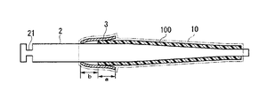
本発明の製造方法では、図1に示すように、強化繊維に熱硬化性樹脂を含浸して得られたプリプレグをマンドレル2の太径側端部が露出するようにマンドレル2に巻きつけて積層してプリプレグ積層体100を得る。
その後、得られたプリプレグ積層体100の末端部と露出したマンドレル2とにかかるようにテープ状プリプレグを巻きつけて補強部3を形成する。その際、テープ状プリプレグを、プリプレグ積層体100の末端部に幅aで、露出したマンドレル2に幅bでかかるように巻きつけて補強部3を形成する。
その後、熱収縮性を有するフィルム10をプリプレグ積層体100と補強部3に巻きつけることが好ましい。
次に、加熱炉で加熱して、プリプレグ積層体100及びテープ状プリプレグ中の熱硬化性樹脂を硬化して、マンドレル2上に補強部3付きゴルフクラブ用シャフトを得る。
In the production method of the present invention, as shown in FIG. 1, a prepreg obtained by impregnating a reinforcing fiber with a thermosetting resin is wound around a mandrel 2 so that the large-diameter side end of the mandrel 2 is exposed and laminated. Thus, the
Thereafter, the tape-shaped prepreg is wound around the end portion of the obtained
Thereafter, the
Next, it heats with a heating furnace, the thermosetting resin in the prepreg laminated
フィルム10は、熱収縮性を有する合成樹脂製であり、図1に示すように、フィルム10を巻きつけることにより、プリプレグ積層体100と補強部3の形を整えやすい。また、フィルム10が熱収縮性を有することで、加熱により熱硬化性樹脂を硬化させるときに、同時にフィルム10を収縮させることができ、それにより、プリプレグ積層体100と補強部3を引き締めることができ、ボイドのないゴルフクラブ用シャフトを得ることができる。フィルム10は、好ましくは、耐熱性に優れ、安価なポリプロピレンフィルムが良い。
The
従来方法では、加熱炉で加熱することで、炉落ち現象が生じてしまう。炉落ちにより、強化繊維の一部分のみが流動して蛇行し、シャフトの品質が劣化していた。
しかしながら、本発明では、当該補強部3がプリプレグ積層体100及びマンドレル2にかかることで、プリプレグ積層体100とマンドレル2が強固に固定されている。従って、フィルムが熱収縮しても、プリプレグ積層体が細径側に移動しにくくなっている。これにより、炉落ち現象が生じにくくなり、強化繊維の蛇行による品質劣化を防止することができる。
In the conventional method, a furnace dropping phenomenon occurs by heating in a heating furnace. Due to the furnace dropping, only a part of the reinforcing fibers flowed and meandered, and the quality of the shaft was deteriorated.
However, in the present invention, the reinforcing portion 3 is applied to the
前記テープ状プリプレグを巻きつけて形成した補強部3とプリプレグ積層体100とが重なっている部分の幅が10mm以上(図1の幅a)であり、かつ、露出したマンドレル2に10mm以上(図1の幅b)かかるように巻きつけることが好ましい。
成形後、プリプレグ積層体100にかかる部分の補強部の幅a(図1)が10mm以上あることで、加熱する際の炉落ち現象をより生じにくくできると共に、補強部3が、研磨工程においてゴルフクラブ用シャフトの太径側端部を保護する保護層としての役割を果たす。また、マンドレル2にかかる部分の補強部の幅b(図1)が10mm以上あることで、加熱する際の炉落ち現象をより生じにくくできる。
テープ状プリプレグの幅は20〜60mmであることが好ましい。これにより、補強部の幅を確保することができ、研磨工程においてゴルフクラブ用シャフトの太径側端部を保護する保護層としての役割を果たし、加熱する際の炉落ち現象をより生じにくくできる。
The width of the portion where the reinforcing portion 3 formed by winding the tape-shaped prepreg and the
After the molding, the width a (FIG. 1) of the reinforcing portion of the portion applied to the
The width of the tape-shaped prepreg is preferably 20 to 60 mm. As a result, the width of the reinforcing portion can be secured, it serves as a protective layer that protects the large-diameter side end of the golf club shaft in the polishing process, and the furnace falling phenomenon during heating can be made less likely to occur. .
また、補強部3の厚みが0.1〜1mmであるように、テープ状プリプレグを巻きつけることが好ましい。これにより、より一層、炉落ちを生じにくくし、保護層としての強度を上げることができる。 Moreover, it is preferable to wind a tape-shaped prepreg so that the thickness of the reinforcement part 3 is 0.1-1 mm. Thereby, it is possible to further prevent the furnace from dropping, and to increase the strength as the protective layer.
シャフトの原料としての、プリプレグは、強化繊維を平行に引き揃えたものや、製織された強化繊維に熱硬化性樹脂を含浸させてシート状としたものを用いることができる。例えば、平行に引き揃えられた強化繊維を含むUDプリプレグ、製織された強化繊維を含む織物プリプレグなどを使用できる。 The prepreg as the raw material of the shaft may be a prepreg in which reinforcing fibers are aligned in parallel, or a prepreg made into a sheet by impregnating a woven reinforcing fiber with a thermosetting resin. For example, a UD prepreg containing reinforcing fibers arranged in parallel, a woven prepreg containing woven reinforcing fibers, and the like can be used.
プリプレグに使用される強化繊維としては、炭素繊維が好ましいが、炭素繊維の他にも、金属繊維、アラミド繊維、炭化ケイ素繊維、アルミナ繊維、ボロン繊維を単独で使用しても、2種以上を組み合わせて使用してもよい。 Carbon fiber is preferred as the reinforcing fiber used in the prepreg, but in addition to carbon fiber, metal fiber, aramid fiber, silicon carbide fiber, alumina fiber, boron fiber can be used alone or in combination of two or more. You may use it in combination.
補強部、および、ゴルフクラブ用シャフトに使用される強化繊維に含浸させる熱硬化性樹脂にも特に制限はなく、例えば、エポキシ樹脂、不飽和ポリエステル樹脂、アクリル樹脂、フェノール樹脂などが挙げられる。特に、シャフトとして高強度のものを得るためには、エポキシ樹脂が好ましい。
エポキシ樹脂の例として、2官能性エポキシ樹脂では、ビスフェノールA型エポキシ樹脂、ビスフェノールF型エポキシ樹脂、ビスフェノールS型エポキシ樹脂、ビフェニル型エポキシ樹脂、ナフタレン型エポキシ樹脂、ジシクロペンタジエン型エポキシ樹脂、フルオレン型エポキシ樹脂、あるいはこれらを変性したエポキシ樹脂等が挙げられる。3官能以上の多官能性エポキシ樹脂としては、例えばフェノールノボラック型エポキシ樹脂、クレゾール型エポキシ樹脂、テトラグリシジルジアミノジフェニルメタン、トリグリシジルアミノフェノール、テトラグリシジルアミンのようなグリシジルアミン型エポキシ樹脂、テトラキス(グリシジルオキシフェニル)エタンやトリス(グリシジルオキシメタン)のようなグリシジルエーテル型エポキシ樹脂、あるいはこれらを変性したエポキシ樹脂やこれらのエポキシ樹脂をブロム化したブロム化エポキシ樹脂が挙げられる。また、これらエポキシ樹脂を1種単独で使用しても、2種以上を組み合わせて使用してもよい。
さらに熱硬化性樹脂は、硬化剤、離型剤、脱泡剤、紫外線吸収剤、充填材などの各種添加剤などを含有した熱硬化性樹脂組成物の形態で使用されても構わない。
補強部3として使用されるテープ状プリプレグは、ガラスクロスプリプレグであることが好ましい。ガラスクロスプリプレグは、薄く、かつ汎用性が高いため、補強部3として好適に使用される。また、クロスプリプレグとは製織された強化繊維に熱硬化性樹脂を含浸させてシート状としたものであり、強度に優れており、本発明に好適に使用される。
There is no particular limitation on the thermosetting resin impregnated in the reinforcing portion and the reinforcing fiber used for the golf club shaft, and examples thereof include an epoxy resin, an unsaturated polyester resin, an acrylic resin, and a phenol resin. In particular, an epoxy resin is preferable for obtaining a high-strength shaft.
Examples of epoxy resins include bifunctional epoxy resins: bisphenol A type epoxy resin, bisphenol F type epoxy resin, bisphenol S type epoxy resin, biphenyl type epoxy resin, naphthalene type epoxy resin, dicyclopentadiene type epoxy resin, fluorene type Examples thereof include epoxy resins and epoxy resins obtained by modifying them. Examples of the trifunctional or higher polyfunctional epoxy resin include phenol novolac type epoxy resin, cresol type epoxy resin, glycidylamine type epoxy resin such as tetraglycidyldiaminodiphenylmethane, triglycidylaminophenol, tetraglycidylamine, tetrakis (glycidyloxy) Examples thereof include glycidyl ether type epoxy resins such as phenyl) ethane and tris (glycidyloxymethane), epoxy resins obtained by modifying these resins, and brominated epoxy resins obtained by brominating these epoxy resins. Moreover, these epoxy resins may be used individually by 1 type, or may be used in combination of 2 or more type.
Furthermore, the thermosetting resin may be used in the form of a thermosetting resin composition containing various additives such as a curing agent, a release agent, a defoaming agent, an ultraviolet absorber, and a filler.
The tape-shaped prepreg used as the reinforcing portion 3 is preferably a glass cloth prepreg. Since the glass cloth prepreg is thin and highly versatile, it is preferably used as the reinforcing portion 3. The cross prepreg is a sheet formed by impregnating a woven reinforcing fiber with a thermosetting resin, has excellent strength, and is suitably used in the present invention.
次に、マンドレル2が中空部にとどまったままのゴルフクラブ用シャフトからマンドレル2を引き抜く。引き抜きはどのような方法で行っても良い。
マンドレル2は、図1に示すように、その一端に、引き抜きのための部材などを引っ掛ける縮径部21が設けられると良い。それにより、引き抜きが行いやすくなる。
Next, the mandrel 2 is pulled out from the golf club shaft with the mandrel 2 remaining in the hollow portion. The drawing may be performed by any method.
As shown in FIG. 1, the mandrel 2 is preferably provided with a reduced
次に、得られたゴルフクラブ用シャフトの太径側端部を切断する。太径側端部を切断する際は、ゴルフクラブ用シャフトの太径側端部に補強部3が5〜30mm残るように切断する。これにより、図2に示すような、太径側端部に、補強部3が5〜30mm残ったゴルフクラブ用シャフト1を得ることができる。 Next, the large-diameter side end portion of the obtained golf club shaft is cut. When the large diameter side end is cut, the reinforcing part 3 is cut so that 5 to 30 mm remains at the large diameter side end of the golf club shaft. Thereby, as shown in FIG. 2, the golf club shaft 1 in which the reinforcing portion 3 remains at 5 to 30 mm at the end portion on the large diameter side can be obtained.
次に、ゴルフクラブ用シャフト1の表面を研磨することが好ましい。これにより、平滑化すると同時に、製品に必要な各種物性を付与したゴルフクラブ用シャフトを得ることができる。 Next, it is preferable to polish the surface of the golf club shaft 1. Thereby, it is possible to obtain a golf club shaft which is smoothed and has various physical properties necessary for the product.
研磨は、図2に示すような、研磨布が外周面に取り付けられた研磨ロール4とゴムロール5を有する研磨機によって行う。研磨機は円柱状の研磨ロール4と円柱状のゴムロール5を有していれば良く、研磨ロール4はゴルフクラブ用シャフト1の表面の研磨を行い、ゴムロール5はゴルフクラブ用シャフト1を回転させる。
研磨ロール4とゴムロール5を、図2に示すように、長さ方向の中心軸41及び51を軸として同一方向に回転させ、ゴムロール5によりゴルフクラブ用シャフト1を研磨ロール4とゴムロール5と長さ方向の中心軸11を軸として逆方向に回転させ、研磨ロール4で一定の圧力をかけて研磨させながら、長さ方向(図2の矢印方向)に移動させる。それにより、ゴルフクラブ用シャフト1表面をフィルム10も含め他端(細径側端部)から補強部3を有する一端(太径側端部)に漸次研磨し、ゴルフクラブ用シャフト1の全体を研磨し、平滑化する。
The polishing is performed by a polishing machine having a polishing roll 4 and a
As shown in FIG. 2, the polishing roll 4 and the
シャフト表面を、補強部3を有しない細径側端部から補強部3を有する太径側端部に、漸次研磨し平滑化する研磨工程において、ゴルフクラブ用シャフト1の太径側端部を研磨するとき、研磨機の研磨布と太径側端部の接触面積が小さくなるため、研磨機からの圧力が集中的に掛かってしまう。従って、従来の末端部が補強されていないゴルフクラブ用シャフト1では、末端部が欠け落ちまたは割れやすく、不良品が生ずることがあった。
しかしながら、本発明では、ゴルフクラブ用シャフト1の太径側端部に補強部3を有する。補強部3は、ゴルフクラブ用シャフト1の太径側端部を保護する保護層としての役割を果たし、シャフト太径側端部を強化することができる。従って、研磨によるシャフト太径側端部の欠け落ちまたは割れが起こりにくくなる。それにより、不良品も生じにくくなる。
In the polishing step of gradually polishing and smoothing the shaft surface from the small-diameter side end portion having no reinforcing portion 3 to the large-diameter side end portion having the reinforcing portion 3, the large-diameter side end portion of the golf club shaft 1 is When polishing, the contact area between the polishing cloth and the large-diameter side end of the polishing machine becomes small, so that pressure from the polishing machine is concentrated. Therefore, in the conventional golf club shaft 1 in which the end portion is not reinforced, the end portion is easily chipped or broken, and a defective product may occur.
However, in the present invention, the golf club shaft 1 has the reinforcing portion 3 at the end on the large diameter side. The reinforcing portion 3 serves as a protective layer for protecting the large-diameter side end portion of the golf club shaft 1 and can reinforce the shaft large-diameter side end portion. Therefore, chipping or cracking of the end portion on the large diameter side of the shaft due to polishing is less likely to occur. Thereby, defective products are less likely to occur.
本発明により製造されたゴルフクラブ用シャフトは、その一端に補強部を有している。補強部によりその末端部が補強され、末端部を切断しても、末端部がささくれにくくなる。例えば、ゴルフクラブにユーザーが改良を加えることがある。そのときに、シャフトの末端部を切断することがある。このように末端部を切断するときに、補強部がないと、末端部の切断面がささくれやすかったが、補強部により、末端部が強化され、切断しても、ささくれにくくなる。 The golf club shaft manufactured according to the present invention has a reinforcing portion at one end thereof. The end portion is reinforced by the reinforcing portion, and even if the end portion is cut, the end portion is hardly raised. For example, a user may improve a golf club. At that time, the end of the shaft may be cut. In this way, when the end portion is cut, if the reinforcing portion is not provided, the cut surface of the end portion is easily raised. However, the reinforcing portion strengthens the end portion, and even if it is cut, it is difficult to raise.
本発明のゴルフクラブ用シャフトの製造方法によると、補強部によりプリプレグ積層体とマンドレルが強固に固定されることで、フィルムの熱収縮による炉落ち現象が生じにくくなり、強化繊維の蛇行による品質劣化を防止することができる。また、ゴルフクラブ用シャフトに補強部があることで、研磨工程における末端部の欠け落ちまたは割れが起こりにくくなり、研磨工程の不良品の問題も解消することができる。 According to the method for manufacturing a golf club shaft of the present invention, the prepreg laminate and the mandrel are firmly fixed by the reinforcing portion, so that a furnace dropping phenomenon due to heat shrinkage of the film is less likely to occur, and quality deterioration due to meandering of reinforcing fibers Can be prevented. Further, since the golf club shaft has the reinforcing portion, the end portion is not easily chipped or cracked in the polishing process, and the problem of defective products in the polishing process can be solved.
1 ゴルフクラブ用シャフト
2 マンドレル
3 補強部
10 フィルム
100 プリプレグ積層体
a 補強部の幅(プリプレグ積層体に重なる部分)
b 補強部の幅(マンドレルにかかる部分)
DESCRIPTION OF SYMBOLS 1 Golf club shaft 2 Mandrel 3
b Width of reinforcement (portion on mandrel)
Claims (6)
(1)強化繊維に熱硬化性樹脂を含浸して得られたプリプレグをマンドレルの太径側端部が露出するようにマンドレルに巻きつけて積層してプリプレグ積層体を得る、
(2)得られたプリプレグ積層体の末端部と露出したマンドレルとにかかるようにテープ状プリプレグを巻きつけて補強部を形成する、
(3)加熱して、プリプレグ及びテープ状プリプレグ中の熱硬化性樹脂を硬化して、マンドレル上に補強部付きゴルフクラブ用シャフトを得る、
(4)前記マンドレルを補強部付きゴルフクラブ用シャフトから引き抜く、
(5)ゴルフクラブ用シャフトの太径側端部に補強部が5〜30mm残るように、補強部付きゴルフクラブ用シャフトの太径側端部を切断して、太径側端部を補強したゴルフクラブ用シャフトを得る The manufacturing method of the shaft for golf clubs which reinforced the large diameter side edge part which performs the following (1)-(5) in order.
(1) A prepreg laminate is obtained by winding a prepreg obtained by impregnating a reinforcing fiber with a thermosetting resin around a mandrel so that the large-diameter side end of the mandrel is exposed, and laminating.
(2) A tape-shaped prepreg is wound around the end portion of the obtained prepreg laminate and the exposed mandrel to form a reinforcing portion.
(3) Heat to cure the thermosetting resin in the prepreg and the tape-shaped prepreg to obtain a golf club shaft with a reinforcing portion on the mandrel.
(4) Pulling out the mandrel from the golf club shaft with a reinforcing portion,
(5) The large-diameter side end of the golf club shaft with a reinforcing portion was cut to reinforce the large-diameter side end so that the reinforcing portion remains at 5-30 mm at the large-diameter side end of the golf club shaft. Get a golf club shaft
A golf club shaft having a reinforcing portion on an outer peripheral surface of a large-diameter side end portion of a tapered golf club shaft.
Priority Applications (1)
| Application Number | Priority Date | Filing Date | Title |
|---|---|---|---|
| JP2007148038A JP2008295940A (en) | 2007-06-04 | 2007-06-04 | Manufacturing method of golf club shaft and golf club shaft |
Applications Claiming Priority (1)
| Application Number | Priority Date | Filing Date | Title |
|---|---|---|---|
| JP2007148038A JP2008295940A (en) | 2007-06-04 | 2007-06-04 | Manufacturing method of golf club shaft and golf club shaft |
Publications (2)
| Publication Number | Publication Date |
|---|---|
| JP2008295940A true JP2008295940A (en) | 2008-12-11 |
| JP2008295940A5 JP2008295940A5 (en) | 2010-07-01 |
Family
ID=40170024
Family Applications (1)
| Application Number | Title | Priority Date | Filing Date |
|---|---|---|---|
| JP2007148038A Pending JP2008295940A (en) | 2007-06-04 | 2007-06-04 | Manufacturing method of golf club shaft and golf club shaft |
Country Status (1)
| Country | Link |
|---|---|
| JP (1) | JP2008295940A (en) |
Cited By (3)
| Publication number | Priority date | Publication date | Assignee | Title |
|---|---|---|---|---|
| JP2010136908A (en) * | 2008-12-12 | 2010-06-24 | Yokohama Rubber Co Ltd:The | Method of manufacturing golf club shaft |
| US8241139B2 (en) | 2010-02-24 | 2012-08-14 | Sri Sports Limited | Golf club |
| JP2013223467A (en) * | 2012-04-23 | 2013-10-31 | Shimano Inc | Method for production of rod pipe for fishing rod |
Citations (6)
| Publication number | Priority date | Publication date | Assignee | Title |
|---|---|---|---|---|
| JPH03151989A (en) * | 1989-11-08 | 1991-06-28 | Daiwa Golf Kk | Tubular article and making thereof |
| JPH09117965A (en) * | 1995-10-25 | 1997-05-06 | Daiwa Seiko Inc | Tubular object |
| JPH10263124A (en) * | 1997-03-28 | 1998-10-06 | Sumitomo Rubber Ind Ltd | Process for manufacturing golf club shaft |
| JPH11164919A (en) * | 1997-12-04 | 1999-06-22 | Mitsubishi Rayon Co Ltd | Shaft for golf club |
| JPH11216206A (en) * | 1997-11-26 | 1999-08-10 | Mitsubishi Rayon Co Ltd | Shaft for golf club and its production |
| JP2001009924A (en) * | 1999-06-25 | 2001-01-16 | Shimano Inc | Manufacture of tubular molding |
-
2007
- 2007-06-04 JP JP2007148038A patent/JP2008295940A/en active Pending
Patent Citations (6)
| Publication number | Priority date | Publication date | Assignee | Title |
|---|---|---|---|---|
| JPH03151989A (en) * | 1989-11-08 | 1991-06-28 | Daiwa Golf Kk | Tubular article and making thereof |
| JPH09117965A (en) * | 1995-10-25 | 1997-05-06 | Daiwa Seiko Inc | Tubular object |
| JPH10263124A (en) * | 1997-03-28 | 1998-10-06 | Sumitomo Rubber Ind Ltd | Process for manufacturing golf club shaft |
| JPH11216206A (en) * | 1997-11-26 | 1999-08-10 | Mitsubishi Rayon Co Ltd | Shaft for golf club and its production |
| JPH11164919A (en) * | 1997-12-04 | 1999-06-22 | Mitsubishi Rayon Co Ltd | Shaft for golf club |
| JP2001009924A (en) * | 1999-06-25 | 2001-01-16 | Shimano Inc | Manufacture of tubular molding |
Cited By (3)
| Publication number | Priority date | Publication date | Assignee | Title |
|---|---|---|---|---|
| JP2010136908A (en) * | 2008-12-12 | 2010-06-24 | Yokohama Rubber Co Ltd:The | Method of manufacturing golf club shaft |
| US8241139B2 (en) | 2010-02-24 | 2012-08-14 | Sri Sports Limited | Golf club |
| JP2013223467A (en) * | 2012-04-23 | 2013-10-31 | Shimano Inc | Method for production of rod pipe for fishing rod |
Similar Documents
| Publication | Publication Date | Title |
|---|---|---|
| KR101829127B1 (en) | Manufacturing method of tank | |
| US5188872A (en) | Composite structural member with high bending strength | |
| JP4732103B2 (en) | Manufacturing method of tubular member made of fiber reinforced resin | |
| EP0733469A2 (en) | Composite structural member with high bending strength and method of manufacture | |
| JP2008286297A (en) | High-pressure tank manufacturing method | |
| JP2008295940A (en) | Manufacturing method of golf club shaft and golf club shaft | |
| JP6804240B2 (en) | A method for manufacturing a hollow tubular body, a tubular molded body having a bent portion, and a tubular molded body having a bent portion. | |
| US20060218873A1 (en) | Composite architectural column | |
| JPH10329247A (en) | Composite material tubular member | |
| JP4330977B2 (en) | Method for manufacturing tubular body | |
| JP5086691B2 (en) | Winding core manufacturing method | |
| JP2017140809A (en) | Method for manufacturing tank | |
| JP4842081B2 (en) | Manufacturing method of fiber reinforced resin tubular body | |
| US10919239B2 (en) | Method and system for fabricating a composite structure | |
| JP4848238B2 (en) | Manufacturing method of fiber reinforced resin tubular body | |
| JP2008295938A (en) | Manufacturing method of golf club shaft | |
| JP2007216554A (en) | Fiber-reinforced synthetic resin pipe | |
| JP5302514B2 (en) | Manufacturing method of shaft for golf club | |
| CN111758685B (en) | Shaft for sporting goods or fishing tackle | |
| JP2004338270A (en) | Method for producing fiber-reinforced resin composite material and fiber-reinforced resin composite material | |
| US20130248093A1 (en) | Composite structure forming on coefficient of thermal expansion mismatched tooling | |
| JP2002128921A (en) | Prepreg for preventing different levels, manufacturing method of tubular body using the same and tubular body | |
| JP2004074427A (en) | Continuous production method for molded object and molded object | |
| JP5837061B2 (en) | Mold tool | |
| JP6719510B2 (en) | shaft |
Legal Events
| Date | Code | Title | Description |
|---|---|---|---|
| A521 | Written amendment |
Free format text: JAPANESE INTERMEDIATE CODE: A523 Effective date: 20100517 |
|
| A621 | Written request for application examination |
Free format text: JAPANESE INTERMEDIATE CODE: A621 Effective date: 20100517 |
|
| A977 | Report on retrieval |
Free format text: JAPANESE INTERMEDIATE CODE: A971007 Effective date: 20111222 |
|
| A131 | Notification of reasons for refusal |
Free format text: JAPANESE INTERMEDIATE CODE: A131 Effective date: 20120104 |
|
| A02 | Decision of refusal |
Free format text: JAPANESE INTERMEDIATE CODE: A02 Effective date: 20120508 |