JP2008280102A - Work support system, work management system, and work management method - Google Patents
Work support system, work management system, and work management method Download PDFInfo
- Publication number
- JP2008280102A JP2008280102A JP2007123573A JP2007123573A JP2008280102A JP 2008280102 A JP2008280102 A JP 2008280102A JP 2007123573 A JP2007123573 A JP 2007123573A JP 2007123573 A JP2007123573 A JP 2007123573A JP 2008280102 A JP2008280102 A JP 2008280102A
- Authority
- JP
- Japan
- Prior art keywords
- information
- tag
- moving image
- conveyor
- article
- Prior art date
- Legal status (The legal status is an assumption and is not a legal conclusion. Google has not performed a legal analysis and makes no representation as to the accuracy of the status listed.)
- Granted
Links
Images


Abstract
Description
本発明は、コンベアで搬送される物品を容易に抽出できる作業支援システム、作業管理システム、および作業管理方法に関する。 The present invention relates to a work support system, a work management system, and a work management method that can easily extract articles conveyed by a conveyor.
多種多様の生産が行われている生産工程で、不良品や特定の製品(以下、対象物という。)を作業者が抽出するために、作業指示書に従って、対象物の抽出作業が実施されている。しかしながら、コンベアで搬送される対象物を認識することは難しく、抽出漏れや、抽出誤りが発生していた。 In a production process in which a wide variety of production is performed, in order for an operator to extract defective products or specific products (hereinafter referred to as objects), the object extraction work is performed according to the work instructions. Yes. However, it is difficult to recognize the object conveyed by the conveyor, and an extraction omission or an extraction error has occurred.
そのため、生産ライン上で製品不良が発生したときに、製品に取り付けられたICタグの不良情報を読取り、その製品が載せられたパレットを自動的に生産ラインから払い出すことが開示されている(例えば、特許文献1参照)。 Therefore, it is disclosed that when a product defect occurs on the production line, the defect information of the IC tag attached to the product is read, and the pallet on which the product is placed is automatically paid out from the production line ( For example, see Patent Document 1).
生産ラインではないが、手荷物の管理における利便性を向上するために、コンベア上に流れる手荷物について、ICタグリーダで読み込まれた手荷物の識別番号と物品形状を案内表示器に表示する方法が開示されている(例えば、特許文献2参照)。
特許文献1では、コンベアで搬送される物品はパレット上に置かれ、パレットは一列に搬送されている。このため、ICタグリーダによりICタグの不良情報を読み込むことができる。しかしながら、コンベア上に非整列に置かれた複数の物品が搬送された場合には、抽出すべき物品を特定することができず、生産ラインから払い出すことができない問題がある。
In
また、特許文献2では、同様に、コンベアで搬送される物品は、ほぼ整列された状態で載せられているため、コンベア上の手荷物の位置が判定できる。しかしながら、例えば、コンベア上に同一形状の複数の物品が並列に置かれると、物品を特定することができない問題がある。
Similarly, in
本発明は、前記の課題を解決するための発明であって、コンベアで搬送される物品を容易に抽出できる作業支援システム、作業管理システム、および作業管理方法を提供することを目的とする。 The present invention is an invention for solving the above-described problems, and an object thereof is to provide a work support system, a work management system, and a work management method that can easily extract articles conveyed by a conveyor.
前記目的を達成するため、物品を搬送するコンベアの上流側の所定の位置を検出対象領域として配置され、コンベアで搬送される物品に添付された無線ICタグを検出する、個々に位置管理された複数のICタグ検出器(例えば、タグリーダ26)と、コンベア上における無線ICタグの位置を監視する処理装置(例えば、管理サーバ10)とを備え、ICタグ検出器が無線ICタグを検出すると、当該検出にかかる無線ICタグの検出位置と検出時刻とタグ情報とが特定され、これら特定された情報に基づいて作業を支援する作業支援システムにおいて、コンベアの所定の位置を撮影する動画像撮影装置(例えば、カメラ42)と、動画像撮影装置が撮影した動画像に画像処理を行い、所定の物品に視覚的なマーキング処理を行う画像処理装置(例えば、制御部44)と、動画像撮影装置が撮影し、画像処理装置がマーキング処理した動画像を表示する表示装置(例えば、モニタ41)とをさらに備え、処理装置は、ICタグ検出器が無線ICタグを検出することにより特定される、検出位置と検出時刻に加えて、コンベアの搬送速度に基づいて、検出した無線ICタグのコンベアにおける搬送方向の位置を算出し、算出した搬送方向の位置と、検出位置から得られるコンベアの幅方向の位置とから無線ICタグの位置を監視し、検出した無線ICタグのタグ情報が、所定のタグ情報であるか否かを判定し、所定のタグ情報であるときは、画像処理装置に、当該所定のタグ情報を有する無線ICタグのコンベアの幅方向の位置および搬送方向の位置を通知し、画像処理装置に当該通知された位置に対応する物品にマーキングをさせることを特徴とする。 In order to achieve the above-mentioned object, a predetermined position on the upstream side of the conveyor that conveys the article is arranged as a detection target area, and the position of the wireless IC tag attached to the article conveyed by the conveyor is detected and individually managed. A plurality of IC tag detectors (for example, tag reader 26) and a processing device (for example, management server 10) that monitors the position of the wireless IC tag on the conveyor, and when the IC tag detector detects the wireless IC tag, A moving image photographing device for photographing a predetermined position of a conveyor in a work support system that identifies a detection position, a detection time, and tag information of the wireless IC tag related to the detection, and supports the work based on the specified information. (For example, the camera 42) and image processing that performs image processing on a moving image captured by the moving image capturing device and performs visual marking processing on a predetermined article (For example, the control unit 44) and a display device (for example, a monitor 41) that displays a moving image that is captured by the moving image capturing device and processed by the image processing device, and the processing device detects the IC tag. In addition to the detection position and detection time specified by the device detecting the wireless IC tag, the position of the detected wireless IC tag in the conveyor direction is calculated based on the conveyor conveyance speed, and the calculated conveyance The position of the wireless IC tag is monitored from the position in the direction and the position in the width direction of the conveyor obtained from the detection position, and it is determined whether or not the tag information of the detected wireless IC tag is predetermined tag information. When it is the predetermined tag information, the image processing apparatus is notified of the position in the width direction and the conveyance direction of the conveyor of the wireless IC tag having the predetermined tag information, and the image processing apparatus Characterized in that for the marked article corresponding to known positions.
また、前記目的を達成するため、コンベアで搬送される物品の抽出作業を管理する管理サーバ(例えば、管理サーバ10)を有する作業管理システムは、物品を搬送するコンベアの上流側の所定の位置を検出対象領域として複数のタグリーダを配置し、前記検出対象領域をスキャンすることにより物品に添付されているICタグ情報を読取り、管理サーバに物品の位置情報および時間情報を送付するタグスキャン装置(例えば、タグスキャン装置20,30)と、コンベアを撮影する撮影部および撮影部の動画映像情報を表示する表示部を有し、管理サーバに動画映像情報を送付する動画映像装置(例えば、動画映像装置40,50)とを備え、管理サーバは、物品の位置情報および時間情報と、動画映像情報とを基に、指定された物品のコンベア上の物品を特定することを特徴とする。
In order to achieve the above object, a work management system having a management server (for example, the management server 10) that manages the extraction work of articles conveyed by a conveyor has a predetermined position on the upstream side of the conveyor that conveys articles. A tag scanning device (for example, a plurality of tag readers arranged as detection target areas, reads IC tag information attached to an article by scanning the detection target area, and sends position information and time information of the article to a management server (for example, ,
本発明によれば、コンベアで搬送される物品を容易に抽出することができる。 According to the present invention, an article conveyed by a conveyor can be easily extracted.
以下、本発明の実施形態について図面を参照して説明する。
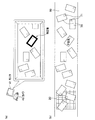
図1は、作業管理システムを示す説明図である。図1において本発明の概要を説明する。作業管理システムは、管理サーバ10と、探索エリア用のタグスキャン装置20と、チェックエリア用のタグスキャン装置30と、探索エリア用の動画映像装置40と、チェックエリア用の動画映像装置50とを有している。管理サーバ10、タグスキャン装置20,30、および動画映像装置40,50は、ネットワーク65を介して接続されている。
Embodiments of the present invention will be described below with reference to the drawings.
FIG. 1 is an explanatory diagram showing a work management system. The outline of the present invention will be described with reference to FIG. The work management system includes a
タグスキャン装置20は、コンベア60を搬送される製品70に付されたICタグ71の情報を、コンベア60の下部に設置された複数のタグリーダ26(図3参照)を用いて探索エリアをスキャンして読取る。動画映像装置40は、カメラ42を用いて、コンベア60で搬送される製品70を撮影する。管理サーバ10は、タグスキャン装置20からのスキャン情報(位置情報、タグ情報、時間情報)と、動画映像装置40からの動画映像情報とを基に、コンベア60の搬送速度を考慮して抽出する製品を特定し、動画映像装置40へ製品(特定物)のマーキング情報(図16参照)を送信する。動画映像装置40は、マーキング情報を受信すると、モニタ41に、作業指示として抽出する特定物を強調して表示する。
The
作業者は、モニタ41に表示された特定物を確認し抽出する。タグスキャン装置30および動画映像装置50は、チェック用の装置であり、作業者によって特定物の抽出が完了したか否かが、モニタ51により、確認することができる。
The worker confirms and extracts the specific object displayed on the
タグスキャン装置30は、コンベア60を搬送される製品70に付されたICタグ71の情報を、コンベア60の下部に設置された複数のタグリーダ36(図3参照)を用いてチェックエリアをスキャンして読取る。動画映像装置50は、カメラ52を用いて、コンベア60で搬送される製品70を撮影する。管理サーバ10は、タグスキャン装置30からのスキャン情報(位置情報、タグ情報、時間情報)と、動画映像情報とを基に、コンベア60の搬送速度を考慮して抽出する製品を特定し、動画映像装置50のモニタ51に、作業指示として特定物を強調して表示する。作業者が特定物の抽出ができている場合は、特定物は表示されず、作業者により抽出が完了していることが確認できる。
The
なお、タグリーダ26,36は、コンベア60の搬送面の下部に設置しているが、製品70の搬送に障害がなければ、コンベア60の搬送面と所定の間隔を設けて上面に設置してもよい。この場合、カメラ42,52の撮影エリアと重ならないようにするのがよい。
The
図2は、作業指示画面を示す説明図である。図2(a)は、モニタ41の表示画面例を示し、図2(b)には、コンベア60上の製品70の搬送状態を示す。モニタ41の表示画面例では、カメラ42で撮影された実映像の上に特定物を強調色で強調されている。特定物の位置は、コンベア60上の不良品の位置に対応している。作業者は、モニタ41上に表示される特定物を確認することにより容易に特定物を抽出することができる。
FIG. 2 is an explanatory diagram showing a work instruction screen. 2A shows an example of a display screen of the
以下、作業管理システムについて、図面を参照して詳細に説明する。
図3は、作業管理システムの構成を示すブロック図である。管理サーバ10は、通信部13、制御部14、記憶部15、操作部16、およびモニタ17を有している。タグスキャン装置20は、通信部23、制御部24、記憶部25、および複数のタグリーダ26を有している。同様に、タグスキャン装置30は、通信部33、制御部34、記憶部35、および複数のタグリーダ36を有している。動画映像装置40は、通信部43、制御部44、記憶部45、カメラ42、およびモニタ41を有している。同様に、動画映像装置50は、通信部53、制御部54、記憶部55、カメラ52、およびモニタ51を有している。通信部13,23,33,43,53は、ネットワーク65を介して、データのやり取りを行うためのインタフェースである。制御部14,24,34,44,54は、記憶部15,25,35,45,55に格納されたプログラムを実行することで、各構成要素(例えば、通信部13,23,33,43,53)を統括的に制御し、様々な演算処理を行う。記憶部15,25,35,45,55は、プログラムやデータを永続的に記憶するために用いられるものであり、ハードディスクなどで構成される。モニタ17,41,51は、管理者、作業者などに対して、メッセージなどを表示するために用いられるものであり、CRT(Cathode Ray Tube)や液晶ディスプレイなどで構成される。操作部16は、データや命令などを入力するために用いられるものであり、キーボードやマウスなどで構成される。タグリーダ26,36は、ICタグ71(図1参照)を読取るためのリーダである。なお、ICタグ71(図1参照)は、RFID(Radio frequency identification)などの非接触の無線用ICタグである。ICタグ71に記憶されているICタグ情報については、図6にて説明する。
Hereinafter, the work management system will be described in detail with reference to the drawings.
FIG. 3 is a block diagram showing the configuration of the work management system. The
タグスキャン装置20は、管理サーバ10から、抽出製品登録情報(抽出すべきタグID)を受信すると、検索エリア(図1参照)に配置された複数のタグリーダ26により、検索エリアをスキャンし、読取ったスキャン情報を管理サーバ10に送信する。スキャン情報にはタグID、位置情報、時間情報が含まれる。抽出製品登録情報、スキャン情報については、図10〜図12にて説明する。
Upon receiving the extracted product registration information (tag ID to be extracted) from the
同様に、タグスキャン装置30は、管理サーバ10から、抽出すべきタグIDを受信すると、検索エリア(図1参照)に配置された複数のタグリーダ36により、検索エリアをスキャンし、読取ったスキャン情報を管理サーバ10に送信する。スキャン情報にはタグID、位置情報、時間情報が含まれる。
Similarly, when the
図4は、タグスキャン装置のタグリーダ配置構成を示す説明図である。図4に示すように(適宜図1、図3参照)、タグスキャン装置20,30のタグリーダ26,36は、コンベア60の下部に複数設置され、探索エリアまたはチェックエリアを通過するICタグ71の識別情報を読取る。図4においては、製品の流れ(X座標方向)に対し、検索エリアを10等分し、X座標と直交するY座標に対して、コンベア60の幅を10等分している。各区画(X座標.Y座標)に関連付けて、複数のタグリーダ26,36が配置されている。これにより、ICタグ71の位置情報は、例えば、(X座標.Y座標)=(4.3)として得ることができる。
FIG. 4 is an explanatory diagram showing a tag reader arrangement configuration of the tag scanning device. As shown in FIG. 4 (see FIGS. 1 and 3 as appropriate), a plurality of
図3に戻り、動画映像装置40は、管理サーバ10から撮影開始情報を受信すると、カメラ42からのコンベア60の動画映像情報を、モニタ41に映すとともに、管理サーバ10に送信する。また、抽出製品情報を受信すると、動画映像情報の抽出製品にマーキング処理を施し、モニタ41に映す。
Returning to FIG. 3, when receiving the shooting start information from the
同様に、動画映像装置50は、管理サーバ10から撮影開始情報を受信すると、カメラ52からのコンベア60の動画映像情報を、モニタ51に映すとともに、管理サーバ10に送信する。また、抽出製品情報を受信すると、動画映像情報の抽出製品にマーキング処理を施し、モニタ51に映す。
Similarly, when receiving the shooting start information from the
管理サーバ10は、操作部16から作業指示されると、抽出製品登録情報を、タグスキャン装置20に送信するとともに、撮影開始情報を動画映像装置40に送信する。そして、タグスキャン装置20からスキャン情報を受信するとともに、動画映像装置40から動画映像情報を受信する。管理サーバ10は、スキャン情報と動画映像情報を基に、抽出製品を特定すると、動画映像装置40に抽出製品情報を送信する。管理サーバ10の機能は図5にてさらに詳しく説明する。
When a work instruction is given from the
図5は、管理サーバの機能を示す構成図である。管理サーバ10の制御部14(図3参照)は、スキャン情報処理部87と、スキャン情報解析部88と、スキャン情報蓄積部89と、動画映像処理部81と、動画映像解析部82と、動画映像蓄積部83と、判定部86と、抽出製品監視処理部85と、編集部84と、および抽出製品情報格納部90を備える。記憶部15(図3参照)には、設備管理DB91と、品質管理DB92と、抽出製品登録情報DB93とを備える。
FIG. 5 is a configuration diagram illustrating functions of the management server. The control unit 14 (see FIG. 3) of the
スキャン情報処理部87は、通信部13を介して、タグスキャン装置20(図3参照)からスキャン情報を受信すると、スキャン情報解析部88とスキャン情報蓄積部89に送信する。スキャン情報解析部88は、スキャン情報から抽出製品の位置情報を確定する。
Upon receiving scan information from the tag scanning device 20 (see FIG. 3) via the
一方、動画映像処理部81は、通信部13を介して、動画映像装置40(図3参照)から動画像情報を受信すると、動画映像解析部82と動画映像蓄積部83に送信する。動画映像解析部82は、動画像情報から、対象物を輪郭処理などにより抽出し、対象物の位置情報を確定する。判定部86は、抽出製品情報格納部90から読み出した抽出製品登録情報と、スキャン情報解析部88から取得した抽出製品の位置情報と、動画映像解析部82から取得した製品の位置情報とから、抽出製品か否かを判定する。抽出製品であると判定されると、抽出製品監視処理部85は、コンベア速度(図7参照)などを考慮して抽出製品の所定時間後の位置情報を算出し、編集部84へ送付する。また、抽出製品監視処理部85は、処理結果に不具合などあれば(例えば、推定位置に該当する製品が存在しないならば)、不具合情報を動画映像蓄積部83およびスキャン情報蓄積部89に送信するとともに、再度、動画映像解析部82およびスキャン情報解析部88に問合せる。編集部84は、所定時間後の位置情報に基づいてマーキング情報を作成し、通信部13を介して、動画映像装置40に、マーキング情報を送信する。なお、さらに詳細な説明は、図16にて行う。なお、抽出製品情報格納部90は、操作部16(図3参照)からの抽出条件に基づいて、判定部86に入力される抽出製品登録情報の一時的な記憶格納部である。
On the other hand, when the moving image
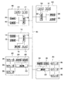
図6は、ICタグに記憶されるICタグ情報を示す説明図である。ICタグ71には、タグID、ロット番号(ロットNo.)、製品コード、製造工場、ライン番号(ラインNo.)、製造日、保障期限、保管期限が記憶されている。図6によれば、例えば、タグIDがaaaの場合、ロットNo.が20070203−3AAA、製品コードがAAAAであり、NK工場の3番ラインで製造されていることがわかる。また、タグIDのaaaとbbbとは同じ情報が記録されていることから、同一製品、同一ロット、同一製造ラインで製造されたこともわかる。
FIG. 6 is an explanatory diagram showing IC tag information stored in the IC tag. The
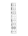
図7は、設備管理DBに記憶される設備使用情報テーブルを示す説明図である。設備管理DB91には、搬出ライン番号(搬出ラインNo.)、開始予定時間、終了予定時間、開始実績時間、終了実績時間、ロット番号(ロットNo.)、コンベア速度、担当者が記憶されている。図7によれば、例えば、搬出ラインの15番は、9時50から開始され、ロットNo.が20070203−3AAAの製品が、コンベア速度0.5m/sで搬送されていることがわかる。
FIG. 7 is an explanatory diagram showing an equipment usage information table stored in the equipment management DB. The
図8は、品質管理DBに記憶される品質管理情報テーブルを示す説明図である。品質管理DB92は、ロット番号(ロットNo.)、製品コード、製造工場、ライン番号(ラインNo.)、搬送ライン番号(搬送ラインNo.)、製造日、保障期限、保管期限、タグID、検査予定数量、検査場数量、検査実績数量、品質情報、担当者が記憶されている。特に、検査結果に重要となる品質情報は、良品の場合フラグ値は0であり、不良品の場合フラグ値は1である。図8によれば、例えば、タグIDがaaaの場合は不良品とされていることがわかる。
FIG. 8 is an explanatory diagram showing a quality management information table stored in the quality management DB. The
図9は、抽出製品登録情報DBに記憶される抽出管理情報テーブルを示す説明図である。抽出製品登録情報DB93は、品質情報が不良品の製品で、抽出状況を管理するデータベースであり、ロット番号(ロットNo.)、製品コード、製造工場、ライン番号(ラインNo.)、搬送ライン番号(搬送ラインNo.)、製造日、保障期限、保管期限、タグID、品質情報、抽出情報、担当者が記憶されている。特に、抽出結果に重要となる抽出情報は、未抽出の場合フラグ値は0であり、抽出完了(抽出完)の場合フラグ値は1である。
FIG. 9 is an explanatory diagram showing an extraction management information table stored in the extracted product registration information DB. The extracted product
図10は、抽出製品のタグIDを示す説明図である。図10には(適宜図3、図5参照)、管理サーバ10からタグスキャン装置20またはタグスキャン装置30に送信される抽出製品登録情報の一例として、タグIDを示している。他の抽出製品登録情報には、図9に示すように、ロット番号(ロットNo.)、製品コード、製造工場、ライン番号(ラインNo.)、製造日、保障期限、保管期限があり、図6のICタグ情報に含まれるものであればよい。抽出製品のタグID情報は、抽出製品情報格納部90(図5参照)に格納されており、判定部86において判定する情報として利用される。
FIG. 10 is an explanatory diagram showing the tag ID of the extracted product. FIG. 10 (see FIGS. 3 and 5 as appropriate) shows a tag ID as an example of extracted product registration information transmitted from the
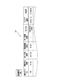
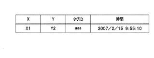
図11は、タグリーダのスキャン情報を示す説明図である。タグスキャン装置20の制御部24(図3参照)は、タグリーダ26からのスキャン情報を記憶部25に格納する。スキャン情報には、X座標、Y座標、タグID、スキャン時の時間(時刻)が記憶されている。図11によれば、例えば、探索エリア内にタグIDがaaaとbbbの製品があることがわかる。タグスキャン装置30においてもスキャン情報は同様である。
FIG. 11 is an explanatory diagram showing scan information of the tag reader. The control unit 24 (see FIG. 3) of the
図12は、抽出製品に該当するタグリーダのスキャン情報を示す説明図である。タグスキャン装置20の制御部24(図3参照)は、図11に示したスキャン情報から抽出製品に該当するスキャン情報を、管理サーバ10へ送信する。送信するスキャン情報には、X座標、Y座標、タグID、スキャン時の時間(時刻)が含まれる。図12によれば、図10に示す管理サーバ10から送信されたタグIDがaaaであるので、タグIDがaaaのスキャン情報であることがわかる。タグスキャン装置30においても送信するスキャン情報は同様である。
FIG. 12 is an explanatory diagram showing scan information of the tag reader corresponding to the extracted product. The control unit 24 (see FIG. 3) of the
図13は、動画映像情報を示す説明図である。動画映像装置40,50から管理サーバ10に送信される動画映像情報は、X座標、Y座標、色相、明度、彩度、撮影の時間(時刻)である。図13によれば、色には、色相(色合いの違い)、明度(明るさの違い)、彩度(鮮やかさの違い)の3つの属性があり、全ての色はこの組み合わせで表現でき、しかも256の分解能で表現されている。
FIG. 13 is an explanatory diagram showing moving image information. The moving image information transmitted from the moving
図14は、抽出製品情報を示す説明図である。管理サーバ10から動画映像装置40,50へ送信される抽出製品情報は、所定時間後の位置を示すマーキング情報である。抽出製品情報には、X座標、Y座標、色相、明度、彩度が含まれる。マーキング情報については、図16にて詳細を説明する。
FIG. 14 is an explanatory diagram showing extracted product information. The extracted product information transmitted from the
次に、処理について、適宜図1〜図5を参照して説明する。
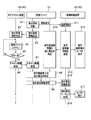
図15は、作業管理システムの処理の全体を示すフローチャートである。図15において、処理の全体概要を説明する。管理サーバ10は、管理サーバの操作部16を介して抽出開始情報が登録されると(ステップS1)、管理サーバ10は、作業管理システムを起動する。管理サーバ10は、品質管理DB92から、品質情報のフラグ値が1(不良品)を抽出し、抽出製品登録情報DB93へ抽出すべき抽出登録情報を登録する。管理サーバ10は、抽出製品登録情報DB93のうちの所定の抽出製品情報を抽出製品情報格納部90に格納し、抽出製品登録情報を、タグスキャン装置20に送信する(ステップS2)。ここでは、抽出製品登録情報として、タグID(図10参照)として説明する。
Next, processing will be described with reference to FIGS.
FIG. 15 is a flowchart showing the entire processing of the work management system. In FIG. 15, the overall outline of the process will be described. When the extraction start information is registered via the
タグスキャン装置20は、抽出製品登録情報を受信すると(ステップS3)、検索エリアを所定時間毎にスキャンする(ステップS4)。例えば、1/60秒間隔でスキャンする。タグスキャン装置20は、スキャン情報(図11参照)を記憶部25に記憶し、制御部24は、抽出製品登録情報であるタグIDに一致するか否かを判定する(ステップS5)。タグスキャン装置20は、タグIDに一致した場合(ステップS5,Yes)、該当するスキャン情報(図12参照)を管理サーバ10に送信する(ステップS6)。タグIDに一致しない場合(ステップS5,No)、ステップS4へ戻る。
When receiving the extracted product registration information (step S3), the
一方、ステップS1において、管理サーバ10は、動画映像装置40に撮影開始信号を送信すると、動画映像装置40は、撮影を開始する(ステップS11)。動画映像装置40は、カメラ42からの実写の動画像情報をモニタ41に送信し映す(ステップS12、ステップS14)。また、動画映像装置40は、実写の動画像情報(図13参照)を管理サーバ10に送信する。
On the other hand, when the
管理サーバ10は、動画映像装置40から実写の動画像情報を管理サーバ10に受信すると、動画映像データを基に輪郭処理などにより製品を特定する(ステップS13)。一方、管理サーバ10は、タグスキャン装置20からスキャン情報を受信すると(ステップS7)、抽出製品の時刻毎の位置情報を特定する。そして、スキャン情報と、実写の動画像情報を基に、実写の動画像上の抽出製品を特定する(ステップS8)。管理サーバ10は、抽出製品情報(図14参照)を、動画映像装置40に送信する(ステップS9)。
When the
動画映像装置40は、抽出製品情報を受信すると(ステップS15)、実写の動画像情報に、抽出製品情報を基に特定した抽出製品にマーキング処理をし(ステップS16)、図2(a)に示すようにモニタ41に映す(ステップS17)。
Upon receipt of the extracted product information (step S15), the moving
なお、タグスキャン装置30と、管理サーバ10と、動画映像装置50との関係は、タグスキャン装置20と、管理サーバ10と、動画映像装置40との関係と同様であるので、説明を省略する。
Note that the relationship between the
作業指示の処理について、適宜図5を参照して詳細に説明する。
図16は、管理サーバの処理を示すフローチャートである。図15と同一処理については、同一符号を付している。
The work instruction processing will be described in detail with reference to FIG.
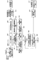
FIG. 16 is a flowchart showing processing of the management server. The same processes as those in FIG. 15 are denoted by the same reference numerals.
ステップS6において、タグスキャン装置20は、スキャン情報として、抽出製品の位置情報、その位置情報を取得した時間を管理サーバ10へ送信すると、管理サーバ10の通信部13は、スキャン情報を受信する(ステップS20)。スキャン情報処理部87は、通信部13を介して、動画映像装置40からスキャン情報を受信すると、スキャン情報解析部88とスキャン情報蓄積部89に送信する(ステップS21)。すると、スキャン情報解析部88は、スキャン情報から抽出製品の位置情報を確定する(ステップS22)。動画映像蓄積部83は、スキャン情報を蓄積する(ステップS23)。
In step S6, when the
ステップS12において、動画映像装置40は、カメラ42で撮影した実写の動画像情報をモニタ41に送信し、モニタ41は、その実写の動画像を映す(ステップS14)。また、動画映像装置40は、実写の動画像情報を管理サーバ10に送信すると、管理サーバ10の通信部13は、実写の動画像情報を受信する(ステップS30)。動画映像処理部81は、通信部13を介して、動画映像装置40から実写の動画像情報を受信すると、動画映像解析部82と動画映像蓄積部83に送信する(ステップS31)。すると、動画映像解析部82は、実写の動画像情報から、対象物を輪郭処理などにより抽出し、対象物の位置情報を確定する(ステップS32)。動画映像蓄積部83は、実写の動画像情報を蓄積する(ステップS33)。ステップS22およびステップS32でのそれぞれの位置情報が確定した時点で、抽出製品情報格納部90は、抽出製品登録情報を判定部86に送信する(ステップS23)。
In step S12, the moving
判定部86は、抽出製品情報格納部90からの抽出製品登録情報と、スキャン情報解析部88からの抽出製品の位置情報と、動画映像解析部82からの対象物の位置情報とから、抽出製品か否かを判定する(ステップS24)。抽出製品と判定されると(ステップS24,Yes)、抽出製品監視処理部85は、抽出製品のα秒(所定時間)後の現在位置を推定し(ステップS25)、編集部84へ送付する。編集部84は、α秒後の位置情報に基づいてマーキング情報を作成し、通信部13を介して、動画映像装置40に、マーキング情報を送信する(ステップS26)。なお、ステップS24において、抽出製品と判定されないと(ステップS24,No)、一連の処理を終了する。
The
動画映像装置40は、受信したα秒後の位置情報であるマーキング情報を基に、マーキング処理し(ステップS16)、実写の動画像にマーキングした動画像をモニタ41に映す(ステップS17)。
The moving
図17は、作業管理システムに抽出装置を設置した例を示す説明図である。図17は、図1に示す作業管理システムにおいて、タグスキャン装置20と、タグスキャン装置30との間のコンベア60上の製品を抽出するための抽出装置100を設置した場合である。管理サーバ10は、抽出装置100の抽出範囲内に到達する所定時間後の抽出製品の位置情報を抽出装置100へ送信すると、抽出装置100は、該当する製品を抽出することができる。
FIG. 17 is an explanatory diagram illustrating an example in which an extraction device is installed in the work management system. FIG. 17 shows a case where an extraction device 100 for extracting products on the
本実施形態によれば、作業管理システムは、コンベアで搬送される物品の抽出作業を管理する管理サーバ10、コンベアの搬送面の下部に複数のタグリーダを有し、タグリーダをスキャンすることにより物品に添付されているICタグ情報を読取り、管理サーバに物品の位置情報および時間情報を送付するタグスキャン装置20,30と、コンベアを撮影するカメラ42,52と、カメラ42,52の動画映像情報を表示するモニタ41,51を有し、管理サーバ10に動画映像情報を送付する動画映像装置40,50とを備え、管理サーバ10は、物品の位置情報と時間情報と、動画映像情報とを基に、指定された物品のコンベア上の物品を特定するので、コンベアで搬送される物品を容易に抽出するための作業指示をすることができる。
According to the present embodiment, the work management system has a
管理サーバ10は、コンベアの搬送速度を考慮し、指定された物品の所定時間後の物品の位置情報であるマーキング情報を、動画映像装置40,50に送信する。動画映像装置40,50は、管理サーバ10からマーキング情報を受信すると、前記撮影部で撮影された実写の動画像情報に、マーキング情報を付加して前記モニタ41,51に表示するので、作業者は、容易に抽出するための物品を確認することができる。なお、マーキング情報を付加するとは、マーキング情報を基にマーキング処理をしてもよいし、マーキング情報そのものを表示してもよい。
The
また、本実施形態では、タグスキャン装置20と、タグスキャン装置30との間に抽出装置100を設けているので、マーキング情報を基に指定された物品の抽出を行うことができる。
In the present embodiment, since the extraction device 100 is provided between the
10 管理サーバ
20 タグスキャン装置(探索エリア用)
26 タグリーダ
30 タグスキャン装置(チェックエリア用)
40 動画映像装置(探索エリア用)
41,51 モニタ
42,52 カメラ
50 動画映像装置(チェックエリア用)
60 コンベア
65 ネットワーク
70 製品
71 ICタグ
91 設備管理DB
92 品質管理DB
93 抽出製品登録情報DB
10
26
40 video equipment (for search area)
41, 51
60
92 Quality Management DB
93 Extracted product registration information DB
Claims (12)
前記コンベアの所定の位置を撮影する動画像撮影装置と、
前記動画像撮影装置が撮影した動画像に画像処理を行い、所定の物品に視覚的なマーキング処理を行う画像処理装置と、
前記動画像撮影装置が撮影し、前記画像処理装置がマーキング処理した動画像を表示する表示装置とをさらに備え、
前記処理装置は、
前記ICタグ検出器が無線ICタグを検出することにより特定される、前記検出位置と前記検出時刻に加えて、前記コンベアの搬送速度に基づいて、検出した無線ICタグの前記コンベアにおける搬送方向の位置を算出し、
前記算出した搬送方向の位置と、前記検出位置から得られる前記コンベアの幅方向の位置とから前記無線ICタグの位置を監視し、
前記検出した無線ICタグのタグ情報が、所定のタグ情報であるか否かを判定し、
所定のタグ情報であるときは、前記画像処理装置に、当該所定のタグ情報を有する無線ICタグの前記コンベアの幅方向の位置および搬送方向の位置を通知し、前記画像処理装置に当該通知された位置に対応する物品にマーキングをさせる
ことを特徴とする作業支援システム。 A plurality of individually controlled IC tag detectors that detect a wireless IC tag attached to an article conveyed by the conveyor, with a predetermined position upstream of the conveyor that conveys the article as a detection target region. And a processing device that monitors the position of the wireless IC tag on the conveyor, and when the IC tag detector detects the wireless IC tag, the detection position, detection time, and tag information of the wireless IC tag related to the detection In a work support system that supports work based on the specified information,
A moving image photographing device for photographing a predetermined position of the conveyor;
An image processing device that performs image processing on a moving image photographed by the moving image photographing device and performs visual marking processing on a predetermined article;
A display device for displaying the moving image captured by the moving image capturing device and marked by the image processing device;
The processor is
In addition to the detection position and the detection time, the IC tag detector is detected by detecting the wireless IC tag, and based on the transport speed of the conveyor, the detected wireless IC tag in the transport direction of the conveyor Calculate the position,
Monitoring the position of the wireless IC tag from the calculated position in the conveyance direction and the position in the width direction of the conveyor obtained from the detection position;
It is determined whether the tag information of the detected wireless IC tag is predetermined tag information,
When it is predetermined tag information, the image processing apparatus is notified of the position in the width direction and the conveyance direction of the conveyor of the wireless IC tag having the predetermined tag information, and the image processing apparatus is notified of the notification. A work support system characterized by marking an article corresponding to a specified position.
物品を搬送するコンベアの上流側の所定の位置を検出対象領域として複数のタグリーダを配置し、前記検出対象領域をスキャンすることにより前記物品に添付されているICタグ情報を読取り、前記管理サーバに前記物品の位置情報および時間情報を送付するタグスキャン装置と、
前記コンベアを撮影する撮影部および前記撮影部の動画映像情報を表示する表示部を有し、前記管理サーバに動画映像情報を送付する動画映像装置とを備え、
前記管理サーバは、前記物品の位置情報および時間情報と、前記動画映像情報とを基に、指定された物品の前記コンベア上の物品を特定する
ことを特徴とする作業管理システム。 A work management system having a management server that manages the extraction work of articles conveyed by a conveyor,
A plurality of tag readers are arranged with a predetermined position on the upstream side of the conveyor for conveying the article as a detection target area, and the IC tag information attached to the article is read by scanning the detection target area. A tag scanning device for sending position information and time information of the article;
An imaging unit that captures the conveyor and a display unit that displays moving image information of the imaging unit; and a moving image device that transmits the moving image information to the management server,
The work management system, wherein the management server specifies an article on the conveyor of a designated article based on the position information and time information of the article and the moving image information.
ことを特徴とする請求項2に記載の作業管理システム。 The work management system according to claim 2, wherein the tag scanning device is provided with a plurality of tag readers in the conveying direction of the conveyor and a plurality of tag readers in a direction substantially orthogonal to the conveying direction of the conveyor. .
ことを特徴とする請求項2に記載の作業管理システム。 The said management server considers the conveyance speed of the said conveyor, and transmits the marking information which is the positional information of the said goods after the predetermined time of the designated goods to the said moving image apparatus. The work management system described.
ことを特徴とする請求項4に記載の作業管理システム。 The video image device, when receiving the marking information from the management server, adds the marking information to the moving image information of the real image captured by the imaging unit and displays the marking information on the display unit. Item 5. The work management system according to Item 4.
ことを特徴とする請求項4に記載の作業管理システム。 The work management system according to claim 4, further comprising an extraction device that extracts an article specified based on the marking information.
物品を搬送するコンベアの所定の位置を検出対象領域として複数のタグリーダを配置し、前記検出対象領域をスキャンすることにより前記物品に添付されているICタグ情報を読取り、前記管理サーバに前記物品の位置情報および時間情報を送付する複数のタグスキャン装置と、
前記コンベアを撮影する撮影部および前記撮影部の動画映像を表示する表示部を有し、前記管理サーバに動画映像情報を送付する複数の動画映像装置とを備え、
前記管理サーバは、前記物品の位置情報および時間情報と、前記動画映像情報とを基に指定された物品の前記コンベア上の物品を特定する
ことを特徴とする作業管理システム。 A work management system having a management server that manages the extraction work of articles conveyed by a conveyor,
A plurality of tag readers are arranged with a predetermined position of a conveyor for conveying an article as a detection target area, and the IC tag information attached to the article is read by scanning the detection target area. A plurality of tag scanning devices for sending location information and time information;
A plurality of moving image devices having an image capturing unit that images the conveyor and a display unit that displays the moving image of the image capturing unit, and transmitting moving image information to the management server;
The work management system characterized in that the management server specifies an article on the conveyor of an article designated based on the position information and time information of the article and the moving image information.
前記作業管理システムは、物品を搬送するコンベアの上流側の所定の位置を検出対象領域として複数のタグリーダを配置するタグスキャン装置と、前記コンベアを撮影する撮影部および前記撮影部の動画映像情報を表示する表示部を有する動画映像装置とを備え、
前記タグスキャン装置は、前記検出対象領域をスキャンすることにより前記物品に添付されているICタグ情報を読取り、前記管理サーバに前記物品の位置情報および時間情報を送付し、
前記動画映像装置は、前記管理サーバに前記撮影部で撮影した動画映像情報を送付し
前記管理サーバは、前記物品の位置情報および時間情報と、前記動画映像情報とを基に、指定された物品の前記コンベア上の物品を特定する
ことを特徴とする作業管理方法。 A work management method of a work management system having a management server for managing an extraction work of articles conveyed by a conveyor,
The work management system includes a tag scanning device in which a plurality of tag readers are arranged with a predetermined position upstream of a conveyor that conveys articles as a detection target area, a photographing unit that photographs the conveyor, and moving image information of the photographing unit. A moving image device having a display unit for displaying,
The tag scanning device reads the IC tag information attached to the article by scanning the detection target area, and sends the position information and time information of the article to the management server,
The moving image apparatus sends the moving image information captured by the image capturing unit to the management server, and the management server specifies a specified article based on the position information and time information of the article and the moving image information. The work management method characterized by specifying the article | item on the said conveyor.
前記タグスキャン装置は、前記検出対象領域をスキャンする
ことを特徴とする請求項8に記載の作業管理方法。 The tag scanning device includes a plurality of tag readers in the transport direction of the conveyor, and includes a plurality of tag readers in a direction substantially orthogonal to the transport direction of the conveyor,
The work management method according to claim 8, wherein the tag scanning device scans the detection target area.
ことを特徴とする請求項8に記載の作業管理方法。 The said management server considers the conveyance speed of the said conveyor, and transmits the marking information which is the positional information on the said goods after the predetermined time of the designated goods to the said moving image apparatus. The work management method described.
ことを特徴とする請求項10に記載の作業管理方法。 The video image device, when receiving the marking information from the management server, adds the marking information to the moving image information of the real image captured by the imaging unit and displays the marking information on the display unit. Item 15. The work management method according to Item 10.
前記抽出装置は、前記マーキング情報を基に指定された物品の抽出を行う
ことを特徴とする請求項10に記載の作業管理方法。 The work management system further includes an extraction device,
The work management method according to claim 10, wherein the extraction device extracts an article designated based on the marking information.
Priority Applications (1)
| Application Number | Priority Date | Filing Date | Title |
|---|---|---|---|
| JP2007123573A JP5096787B2 (en) | 2007-05-08 | 2007-05-08 | Work support system, work management system, and work management method |
Applications Claiming Priority (1)
| Application Number | Priority Date | Filing Date | Title |
|---|---|---|---|
| JP2007123573A JP5096787B2 (en) | 2007-05-08 | 2007-05-08 | Work support system, work management system, and work management method |
Publications (2)
| Publication Number | Publication Date |
|---|---|
| JP2008280102A true JP2008280102A (en) | 2008-11-20 |
| JP5096787B2 JP5096787B2 (en) | 2012-12-12 |
Family
ID=40141253
Family Applications (1)
| Application Number | Title | Priority Date | Filing Date |
|---|---|---|---|
| JP2007123573A Expired - Fee Related JP5096787B2 (en) | 2007-05-08 | 2007-05-08 | Work support system, work management system, and work management method |
Country Status (1)
| Country | Link |
|---|---|
| JP (1) | JP5096787B2 (en) |
Cited By (4)
| Publication number | Priority date | Publication date | Assignee | Title |
|---|---|---|---|---|
| JP2010132375A (en) * | 2008-12-02 | 2010-06-17 | Murata Machinery Ltd | Identification data input system |
| KR101492338B1 (en) * | 2013-10-10 | 2015-02-11 | 재단법인대구경북과학기술원 | Method and apparatus for smart managing of product using rf tag and vison sensor |
| JP2016138885A (en) * | 2015-01-27 | 2016-08-04 | ヤンマー株式会社 | Quality screening device |
| WO2019003685A1 (en) * | 2017-06-30 | 2019-01-03 | パナソニックIpマネジメント株式会社 | Baggage determination device, baggage sorting system, and baggage determination method |
Citations (4)
| Publication number | Priority date | Publication date | Assignee | Title |
|---|---|---|---|---|
| JPH08153172A (en) * | 1994-11-28 | 1996-06-11 | Harumi Takeda | Automatic discriminating device |
| JPH09314071A (en) * | 1996-05-24 | 1997-12-09 | Mutual Corp | Visual inspection supporting system |
| JP2007015055A (en) * | 2005-07-07 | 2007-01-25 | Toshiba Mach Co Ltd | Handling device, working device and program |
| JP2007523811A (en) * | 2004-01-23 | 2007-08-23 | ユナイテッド パーセル サービス オブ アメリカ インコーポレイテッド | System and method for tracking and processing goods |
-
2007
- 2007-05-08 JP JP2007123573A patent/JP5096787B2/en not_active Expired - Fee Related
Patent Citations (4)
| Publication number | Priority date | Publication date | Assignee | Title |
|---|---|---|---|---|
| JPH08153172A (en) * | 1994-11-28 | 1996-06-11 | Harumi Takeda | Automatic discriminating device |
| JPH09314071A (en) * | 1996-05-24 | 1997-12-09 | Mutual Corp | Visual inspection supporting system |
| JP2007523811A (en) * | 2004-01-23 | 2007-08-23 | ユナイテッド パーセル サービス オブ アメリカ インコーポレイテッド | System and method for tracking and processing goods |
| JP2007015055A (en) * | 2005-07-07 | 2007-01-25 | Toshiba Mach Co Ltd | Handling device, working device and program |
Cited By (9)
| Publication number | Priority date | Publication date | Assignee | Title |
|---|---|---|---|---|
| JP2010132375A (en) * | 2008-12-02 | 2010-06-17 | Murata Machinery Ltd | Identification data input system |
| KR101492338B1 (en) * | 2013-10-10 | 2015-02-11 | 재단법인대구경북과학기술원 | Method and apparatus for smart managing of product using rf tag and vison sensor |
| JP2016138885A (en) * | 2015-01-27 | 2016-08-04 | ヤンマー株式会社 | Quality screening device |
| WO2019003685A1 (en) * | 2017-06-30 | 2019-01-03 | パナソニックIpマネジメント株式会社 | Baggage determination device, baggage sorting system, and baggage determination method |
| CN110785363A (en) * | 2017-06-30 | 2020-02-11 | 松下知识产权经营株式会社 | Cargo determination device, cargo sorting system, and cargo determination method |
| JPWO2019003685A1 (en) * | 2017-06-30 | 2020-04-23 | パナソニックIpマネジメント株式会社 | Package determination device, package sorting system, and package determination method |
| CN110785363B (en) * | 2017-06-30 | 2022-02-11 | 松下知识产权经营株式会社 | Cargo determination device, cargo sorting system, and cargo determination method |
| US11369999B2 (en) | 2017-06-30 | 2022-06-28 | Panasonic Intellectual Property Management Co., Ltd. | Parcel determination device, parcel sorting system, and parcel determination method |
| JP7174898B2 (en) | 2017-06-30 | 2022-11-18 | パナソニックIpマネジメント株式会社 | Package determination device, package sorting system, and package determination method |
Also Published As
| Publication number | Publication date |
|---|---|
| JP5096787B2 (en) | 2012-12-12 |
Similar Documents
| Publication | Publication Date | Title |
|---|---|---|
| US10198711B2 (en) | Methods and systems for monitoring or tracking products in a retail shopping facility | |
| WO2016117600A1 (en) | Product shelf allocation management device and product shelf allocation management method | |
| EP3434626B1 (en) | Projection instruction device, parcel sorting system, and projection instruction method | |
| JP5069936B2 (en) | Material storage position management system and method | |
| EP3434621B1 (en) | Instruction projecting device, parcel sorting system and instruction projecting method | |
| JP6679442B2 (en) | Package tracking system, package tracking method and package tracking program | |
| JP2019101693A (en) | System for grasping in-physical-distribution-warehouse operation | |
| EP3434623B1 (en) | Projection indicator, cargo assortment system, and projection indicating method | |
| JP5096787B2 (en) | Work support system, work management system, and work management method | |
| JP7471878B2 (en) | Image Processing Device | |
| KR20170055406A (en) | System and method for tracking products | |
| US11120286B2 (en) | Projection indication device, parcel sorting system, and projection indication method | |
| JP2007523810A (en) | Web-based inventory management of goods | |
| EP3647233B1 (en) | Parcel determination device, parcel sorting system, and parcel determination method | |
| JP6728995B2 (en) | Automated warehouse system and automated warehouse management method | |
| JP2018019373A (en) | Monitoring camera and package reading method | |
| EP3689792B1 (en) | Package recognition device, package sorting system and package recognition method | |
| EP3434625B1 (en) | Projection instruction device, parcel sorting system, and projection instruction method | |
| EP3689789B1 (en) | Baggage recognition device, baggage sorting system, and baggage recognition method | |
| JP2017079326A (en) | Identification device, traceability system, and identification method | |
| WO2021067218A4 (en) | X-ray detection of meat | |
| EP3689790A1 (en) | Baggage sorting system | |
| US11417104B2 (en) | Systems and methods for automatically determining location of an object inside a retail store | |
| US10852244B2 (en) | Image processing apparatus, image processing method, and recording medium | |
| EP3434624B1 (en) | Projection instruction device, parcel sorting system, and projection instruction method |
Legal Events
| Date | Code | Title | Description |
|---|---|---|---|
| A621 | Written request for application examination |
Free format text: JAPANESE INTERMEDIATE CODE: A621 Effective date: 20090626 |
|
| A977 | Report on retrieval |
Free format text: JAPANESE INTERMEDIATE CODE: A971007 Effective date: 20111117 |
|
| A131 | Notification of reasons for refusal |
Free format text: JAPANESE INTERMEDIATE CODE: A131 Effective date: 20111122 |
|
| A521 | Written amendment |
Free format text: JAPANESE INTERMEDIATE CODE: A523 Effective date: 20120120 |
|
| TRDD | Decision of grant or rejection written | ||
| A01 | Written decision to grant a patent or to grant a registration (utility model) |
Free format text: JAPANESE INTERMEDIATE CODE: A01 Effective date: 20120911 |
|
| A01 | Written decision to grant a patent or to grant a registration (utility model) |
Free format text: JAPANESE INTERMEDIATE CODE: A01 |
|
| A61 | First payment of annual fees (during grant procedure) |
Free format text: JAPANESE INTERMEDIATE CODE: A61 Effective date: 20120921 |
|
| R150 | Certificate of patent or registration of utility model |
Ref document number: 5096787 Country of ref document: JP Free format text: JAPANESE INTERMEDIATE CODE: R150 Free format text: JAPANESE INTERMEDIATE CODE: R150 |
|
| FPAY | Renewal fee payment (event date is renewal date of database) |
Free format text: PAYMENT UNTIL: 20150928 Year of fee payment: 3 |
|
| LAPS | Cancellation because of no payment of annual fees |