JP2008278738A - Power feed controller - Google Patents
Power feed controller Download PDFInfo
- Publication number
- JP2008278738A JP2008278738A JP2008037351A JP2008037351A JP2008278738A JP 2008278738 A JP2008278738 A JP 2008278738A JP 2008037351 A JP2008037351 A JP 2008037351A JP 2008037351 A JP2008037351 A JP 2008037351A JP 2008278738 A JP2008278738 A JP 2008278738A
- Authority
- JP
- Japan
- Prior art keywords
- power supply
- supply control
- battery
- control device
- unit
- Prior art date
- Legal status (The legal status is an assumption and is not a legal conclusion. Google has not performed a legal analysis and makes no representation as to the accuracy of the status listed.)
- Withdrawn
Links
Images


Classifications
-
- Y—GENERAL TAGGING OF NEW TECHNOLOGICAL DEVELOPMENTS; GENERAL TAGGING OF CROSS-SECTIONAL TECHNOLOGIES SPANNING OVER SEVERAL SECTIONS OF THE IPC; TECHNICAL SUBJECTS COVERED BY FORMER USPC CROSS-REFERENCE ART COLLECTIONS [XRACs] AND DIGESTS
- Y02—TECHNOLOGIES OR APPLICATIONS FOR MITIGATION OR ADAPTATION AGAINST CLIMATE CHANGE
- Y02E—REDUCTION OF GREENHOUSE GAS [GHG] EMISSIONS, RELATED TO ENERGY GENERATION, TRANSMISSION OR DISTRIBUTION
- Y02E60/00—Enabling technologies; Technologies with a potential or indirect contribution to GHG emissions mitigation
- Y02E60/10—Energy storage using batteries
Abstract
Description
本発明は、電池駆動式機器の電池ホルダに装着され、電池の負荷への給電を制御する給電制御装置に関する。 The present invention relates to a power supply control device that is mounted on a battery holder of a battery-driven device and controls power supply to a battery load.
複数の電池を装着可能に構成された、例えばカメラのような電池駆動式機器において、装着した全ての電池を負荷に対して同列には用いず、例えば、二次電池を主電源として主たる負荷に給電すると共に、この二次電池の残容量をモニタして、残容量が所定値を割り込むような状態に到ったときには、別途に装着されている一次電池の起電力を昇圧回路で昇圧し、二次電池の充電に供するといった技術が既に提案されている(特許文献1参照)。 In a battery-powered device such as a camera that is configured so that a plurality of batteries can be mounted, for example, all the mounted batteries are not used in the same row with respect to the load. While supplying power and monitoring the remaining capacity of the secondary battery, when the remaining capacity falls below a predetermined value, the electromotive force of the separately installed primary battery is boosted by a booster circuit, There has already been proposed a technique for charging a secondary battery (see Patent Document 1).
また一方、電池駆動式機器である携帯電話機やPDA(Personal Digital Assistant)等の携帯情報端末装置において、外部のノイズに対しても堅牢な特性を持った通信手段として、ディスプレイ部の点滅を利用した光通信手段をも併用する技術が既に提案されている。
この提案では、別途の装置を付加することなく、アルゴリズムの工夫のみによって光通信をも併用することが出来るとされている(特許文献2参照)。
In this proposal, it is said that optical communication can be used together only by devising an algorithm without adding a separate device (see Patent Document 2).
しかしながら、特許文献1に開示の技術では、電池駆動式機器において少なからぬ容積を占有することとなる複数の電池は、その起電力の低下を補って、外部からの充電や電池の交換を俟つことなく例えばカメラである電池駆動式機器の稼働時間を延長可能にするものではあるが、所詮、電池は電源としてのみ機能して、当該機器の機能を拡張したり多様化するといったものではない。
また一方、特許文献2に開示の技術では、アルゴリズムの工夫のみによって光通信をも併用することが出来るとはいえ、携帯情報端末装置のディスプレイ部の発光では到達距離が局限されてしまうため、通信距離に関する本来の要求を充足するには到らないといった問題がある。
However, in the technique disclosed in
On the other hand, in the technique disclosed in
本発明は上述のような状況に鑑みてなされたものであり、電池駆動式機器の電池ホルダに装着可能に構成されると共に電池の負荷への給電を制御する機能を備えて、当該電池駆動式機器の機能を拡張ないしは多様化することができる給電制御装置を提供し、更にその発展的態様として、電池の負荷への給電を制御する機能を積極的に利用して、携帯情報端末装置のディスプレイ部の発光に比して格段に光の到達距離が長い照明装置から投射される照明光に被送信情報に応じた変調を与えることにより照明光通信を可能にする通信回路モジュールとして機能し、エンドユーザが任意に光通信における送信機能を電池駆動型の照明装置に付加することができる給電制御装置を提供することを目的とする。 The present invention has been made in view of the situation as described above, and is configured to be attachable to a battery holder of a battery-driven device, and has a function of controlling power feeding to a load of the battery. Provided is a power supply control device capable of expanding or diversifying the functions of a device, and as a further development aspect thereof, a function of controlling power supply to a battery load is positively utilized, and a display of a portable information terminal device Functions as a communication circuit module that enables illumination light communication by applying modulation according to transmitted information to illumination light projected from an illuminating device that has an extremely long light reach compared to the light emission of the part. It is an object of the present invention to provide a power supply control device that allows a user to arbitrarily add a transmission function in optical communication to a battery-driven illumination device.
上記課題を解決するべく、本願では次に列記するような技術を提案する。
(1)所定仕様の電池を定格数である複数個保持して該定格数の電池の直列接続によって定格起電力を得るように構成された電池ホルダを備え、前記電池ホルダに装着された電池から所定の負荷に給電するように構成された電池駆動式機器に適用される給電制御装置であって、
前記電池ホルダに当該複数個のうちの一の電池に替えて自己が保持されるに適合する形状・寸法を成し得る外装体と、
前記外装体内に配され、前記外装体が当該一の電池に替えて前記電池ホルダに保持されたときには当該他の電池の起電力の合算値に相応する電圧の供給を受けて該供給された電圧を前記定格起電力に相応する出力電圧に変換するコンバータ部と、
前記コンバータ部の出力を所定の負荷に供給する給電経路に介挿され給電制御信号に応じて前記給電経路を開閉するスイッチ部と、
前記スイッチ部に供給する前記給電制御信号を生成する給電制御部と、を備え、
前記給電制御部が、前記電池駆動式機器の外部から供給される被送信情報を受信する被送信情報受信部を有し、該被送信情報受信部で受信された被送信情報に基づいて前記給電制御信号を生成するように構成されていることを特徴とする給電制御装置。
In order to solve the above problems, the present application proposes the following technologies.
(1) A battery holder configured to obtain a rated electromotive force by holding a plurality of batteries having a predetermined number and having a rated number and connecting the batteries having the rated number in series, and from a battery mounted on the battery holder A power supply control device applied to a battery-driven device configured to supply power to a predetermined load,
An exterior body capable of forming a shape / dimension adapted to be held by the battery holder instead of one of the plurality of batteries;
When the outer body is disposed in the outer body and the outer body is held in the battery holder instead of the one battery, the supplied voltage is supplied with a voltage corresponding to the sum of the electromotive forces of the other batteries. Converter unit for converting the output voltage into an output voltage corresponding to the rated electromotive force,
A switch unit that is inserted in a power supply path that supplies the output of the converter unit to a predetermined load and opens and closes the power supply path according to a power supply control signal;
A power supply control unit that generates the power supply control signal to be supplied to the switch unit, and
The power supply control unit includes a transmitted information receiving unit that receives transmitted information supplied from outside the battery-powered device, and the power supply is performed based on the transmitted information received by the transmitted information receiving unit. A power supply control device configured to generate a control signal.
上記(1)の給電制御装置は、電池駆動式機器の電池ホルダに定格数である複数個の所定仕様の電池(以下、適宜、実電池という)のうちの一の電池に替えて装着されると、コンバータ部が、該複数個の実電池の起電力の合算値に相応する電圧を定格数の実電池が直列接続の配列で装着された場合の電池ホルダからの定格起電力に相応する出力電圧を発生する。
コンバータ部から発生された出力は、例えば上記電池駆動式機器の主要な負荷に供給されるが、この供給に係る給電経路には、給電制御信号に応じて前記給電経路を開閉するスイッチ部が介挿されており、給電制御部から供給される給電制御信号に応じてスイッチ部が開閉動作して、上記負荷への給電が制御される。
The power supply control device of the above (1) is attached to a battery holder of a battery-driven device instead of one of a plurality of batteries having a predetermined number (hereinafter referred to as an actual battery as appropriate). And an output corresponding to the rated electromotive force from the battery holder when the converter unit has a voltage corresponding to the sum of the electromotive forces of the plurality of real batteries and a rated number of real batteries mounted in a series connection arrangement. Generate voltage.
The output generated from the converter unit is supplied to, for example, a main load of the battery-driven device. The power supply path related to this supply is provided with a switch unit that opens and closes the power supply path according to a power supply control signal. The switch unit opens and closes in response to a power supply control signal supplied from the power supply control unit, and power supply to the load is controlled.
この場合、給電制御部は、電池駆動式機器の外部から供給される被送信情報を受信する被送信情報受信部を有し、該被送信情報受信部で受信された被送信情報に基づいて前記給電制御信号を生成する。
電池ホルダ内に実電池に替えて装着される上述のような給電制御装置によって、電池を除く電池駆動式機器本体には遠隔操作可能な構成が備えられていない場合においても、負荷への給電に関して無線信号によって遠隔操作を行うことができ、或いはまた、無線信号によって上記負荷である通信機能部に変調を与えることができる。
In this case, the power supply control unit has a transmitted information receiving unit that receives transmitted information supplied from the outside of the battery-powered device, and based on the transmitted information received by the transmitted information receiving unit A power supply control signal is generated.
Even when the battery-driven device main body excluding the battery is not equipped with a remote-controllable structure by the power supply control device mounted in place of the actual battery in the battery holder, the power supply to the load Remote operation can be performed by a wireless signal, or modulation can be given to the communication function unit as the load by the wireless signal.
(2)前記外装体は、前記電池駆動式機器としての照明装置の電池ホルダに適用されるように構成され、
前記スイッチ部は、前記負荷としての前記照明装置の光源への電源供給経路に介挿されるようにして設けられ、
前記給電制御部は、前記被送信情報受信部で受信された被送信情報に応じて前記光源による照明光に変調を与えるように前記給電制御信号を生成するように構成されていることを特徴とする(1)の給電制御装置。
(2) The exterior body is configured to be applied to a battery holder of a lighting device as the battery-driven device,
The switch unit is provided so as to be inserted in a power supply path to the light source of the lighting device as the load,
The power supply control unit is configured to generate the power supply control signal so as to modulate illumination light from the light source according to the transmitted information received by the transmitted information receiving unit. The power supply control device according to (1).
上記(2)の給電制御装置では、(1)の給電制御装置において特に、例えば、電池駆動型の懐中電灯のような照明装置から投射される照明光に被送信情報に応じた変調を与えることにより照明光通信を可能にする。この場合、給電制御装置は、電池ホルダに装着され該当機器本体側に通信機能を付加する回路ユニットである通信回路モジュールとして機能する。即ち、外部から、例えば、無線信号として或いはセンサによる検出信号として供給される被送信情報を受信する被送信情報受信部で受信された被送信情報に応じて、給電制御部によって、照明光に変調を与えるように照明装置の光源への給電を制御する。
このため、照明装置の光源は被送信情報に応じて点滅するように変調され、例えばモールス信号のような所定のコード体系に準拠した態様の信号として通信相手に投射される。
In the power supply control device of (2), in particular, in the power supply control device of (1), for example, the illumination light projected from the illumination device such as a battery-driven flashlight is modulated according to the transmitted information. Enables illumination light communication. In this case, the power supply control device functions as a communication circuit module that is a circuit unit that is attached to the battery holder and adds a communication function to the corresponding device main body. That is, the power supply control unit modulates illumination light according to the transmitted information received from the outside, for example, the transmitted information receiving unit that receives the transmitted information supplied as a wireless signal or a detection signal from the sensor. The power supply to the light source of the lighting device is controlled so as to provide
For this reason, the light source of the illuminating device is modulated so as to blink in accordance with the transmitted information, and is projected to the communication partner as a signal in a mode conforming to a predetermined code system such as a Morse signal.
(3)前記被送信情報受信部は、所定の移動体通信に適合する短距離高速無線ネットワーク・インターフェースを備え、前記短距離高速無線ネットワーク・インターフェースによって被送信情報を受信するように構成されていることを特徴とする(1)または(2)の給電制御装置。
上記(3)の給電制御装置では、(1)または(2)の給電制御装置において特に、被送信情報受信部は、所定の移動体通信に適合する、例えばブルートゥース(Bluetooth:登録商標)インターフェースのような短距離高速無線ネットワーク・インターフェースによって被送信情報を受信する。即ち、給電制御装置は、例えば、携帯電話機、携帯情報端末などから上述のような形で被送信情報が供給される。
(3) The transmitted information receiving unit includes a short-range high-speed wireless network interface suitable for predetermined mobile communication, and is configured to receive the transmitted information by the short-range high-speed wireless network interface. The power supply control device according to (1) or (2).
In the power supply control device of (3) above, in particular, in the power supply control device of (1) or (2), the transmitted information receiving unit is adapted to a predetermined mobile communication, for example, a Bluetooth (registered trademark) interface. The transmitted information is received by such a short-range high-speed wireless network interface. In other words, the power supply control device is supplied with the transmitted information in the above-described form, for example, from a mobile phone, a portable information terminal, or the like.
(4)前記短距離高速無線ネットワーク・インターフェースは、所定のPDAから発せられる短距離高速無線信号を受信可能に構成されていることを特徴とする(3)の給電制御装置。
上記(4)の給電制御装置では、(3)の給電制御装置において特に、短距離高速無線ネットワーク・インターフェースは、所定のPDAから発せられる、例えばブルートゥース(Bluetooth:登録商標)に準拠した信号として供給される被送信情報を受信する。
このため、所定のPDAを照明光通信装置に対する被送信信号の入力手段として用いて通信を行うことが可能になる。
(4) The power supply control device according to (3), wherein the short-range high-speed wireless network interface is configured to receive a short-range high-speed wireless signal emitted from a predetermined PDA.
In the power supply control device of (4) above, particularly in the power supply control device of (3), the short-distance high-speed wireless network interface is supplied as a signal compliant with, for example, Bluetooth (registered trademark) issued from a predetermined PDA. Received transmission information is received.
For this reason, it is possible to perform communication using a predetermined PDA as an input means for a transmitted signal to the illumination light communication device.
(5)前記被送信情報受信部は、所定の物象の状態の量を検出するセンサによって取得された情報を受けるセンサ・インターフェースを備えていることを特徴とする(1)または(2)の給電制御装置。
上記(5)の給電制御装置では、(1)または(2)の給電制御装置において特に、センサ・インターフェースによって、例えば、温度、圧力、流量、等々の所定の物象の状態の量を検出するセンサによって取得された情報を受ける。このようにして受けた物象の状態の量が該当機器本体側に通信機能を付加する回路ユニットである通信回路モジュールとして機能する上述の給電制御装置を通して、照明装置から照明光通信によって通信相手に伝送される。
(5) The power transmission unit according to (1) or (2), wherein the transmission information receiving unit includes a sensor interface that receives information acquired by a sensor that detects a quantity of a state of a predetermined object. Control device.
In the power supply control device according to (5), in particular, in the power supply control device according to (1) or (2), a sensor that detects the amount of a predetermined physical state such as temperature, pressure, flow rate, and the like by a sensor interface. Receive information obtained by. The amount of the physical state received in this way is transmitted from the lighting device to the communication partner by illumination light communication through the above-described power supply control device that functions as a communication circuit module that is a circuit unit that adds a communication function to the device body side. Is done.
(6)前記センサ・インターフェースは、所定の温度センサによって取得された情報を受けるように構成されていることを特徴とする(5)の給電制御装置。
上記(6)の給電制御装置では、(5)の給電制御装置において特に、温度センサによって取得された被送信情報としての温度の検出値がセンサ・インターフェースから入力され、該当機器本体側に通信機能を付加する回路ユニットである通信回路モジュールとして機能する上述の給電制御装置を通して、照明装置から照明光通信によって通信相手に伝送される。
(6) The power feeding control device according to (5), wherein the sensor interface is configured to receive information acquired by a predetermined temperature sensor.
In the power supply control device of (6) above, in particular, in the power supply control device of (5), the detected temperature value as the transmitted information acquired by the temperature sensor is input from the sensor interface, and the communication function is provided on the corresponding device body side. Is transmitted from the lighting device to the communication partner through the illumination light communication through the above-described power supply control device functioning as a communication circuit module that is a circuit unit for adding.
(7)前記給電制御部は、前記被送信情報受信部で受信した被送信情報が所定のコード体系に準拠した光信号によって担われるように前記給電制御信号を生成することを特徴とする(1)または(2)の給電制御装置。
上記(7)の給電制御装置では、(1)または(2)の給電制御装置において特に、給電制御部は、被送信情報受信部で受信した被送信情報が所定のコード体系に準拠した光信号によって担われるように光源への給電を制御するため、被送信情報は本照明装置の照明光の点滅ないし明滅による信号となって受信系で他の光とは識別可能な態様で通信相手に伝送される。
(7) The power supply control unit generates the power supply control signal so that the transmitted information received by the transmitted information receiving unit is carried by an optical signal conforming to a predetermined code system (1). ) Or (2).
In the power supply control device of (7) above, particularly in the power supply control device of (1) or (2), the power supply control unit is an optical signal in which the transmitted information received by the transmitted information receiving unit conforms to a predetermined code system. In order to control the power supply to the light source to be carried by, the transmitted information becomes a signal due to blinking or flickering of the illumination light of this lighting device, and transmitted to the communication partner in a manner that can be distinguished from other light in the receiving system Is done.
(8)前記外装体は、他の所定の構体との組み合わせによって前記電池ホルダに保持され得る形状・寸法を成すように構成されていることを特徴とする(1)の給電制御装置。
上記(8)の給電制御装置では、(1)の給電制御装置において特に、給電制御装置の外装体は、他の所定の構体との組み合わせた形で電池ホルダに保持され得る。換言すれば、このような外装体を有して構成される給電制御装置のユニット自体は実電池よりも小型であって、他の所定の構体(これ自体も給電制御装置として機能し得るものであり得る)との組み合わせによって一の実電池に相当する形状・寸法を成すように構成される。
(8) The power supply control device according to (1), wherein the exterior body is configured to have a shape and size that can be held by the battery holder in combination with another predetermined structure.
In the power supply control device of (8) above, in particular, in the power supply control device of (1), the exterior body of the power supply control device can be held on the battery holder in combination with another predetermined structure. In other words, the unit itself of the power supply control device configured with such an exterior body is smaller than the actual battery, and can be another predetermined structure (which itself can also function as a power supply control device. And a shape and size corresponding to one real battery.
(9)前記外装体は、前記コンバータ部と共に前記スイッチ部および給電制御部を収容するように構成されていることを特徴とする(1)の給電制御装置。
上記(9)の給電制御装置では、(1)の給電制御装置において特に、給電制御装置の外装体は、(1)の給電制御装置において特に、コンバータ部、スイッチ部および給電制御部が一の外装体内配され、例えば一の実電池に相当する形状・寸法を成す単一のユニットとして構成される。
(9) The power supply control device according to (1), wherein the exterior body is configured to house the switch unit and the power supply control unit together with the converter unit.
In the power supply control device of (9) above, the exterior body of the power supply control device is particularly the same in the power supply control device of (1), and the converter unit, the switch unit, and the power supply control unit are the same in the power supply control device of (1). For example, it is configured as a single unit having a shape and dimensions corresponding to one real battery.
(10)前記構体は、前記スイッチ部および給電制御部を収容するように構成されていることを特徴とする(8)の給電制御装置。
上記(10)の給電制御装置では、(8)の給電制御装置において特に、例えば(8)における外装体にコンバータ部を設けると共に、このような外装体と組み合わせて用いる構体(これ自体も外装体を有するものであり得る)にスイッチ部および給電制御部を収容して、上述の組み合わせにおいて給電制御装置を構成する。
(10) The power feeding control device according to (8), wherein the structure is configured to accommodate the switch unit and the power feeding control unit.
In the power supply control device of (10), in particular, in the power supply control device of (8), for example, the converter body is provided in the exterior body in (8), and the structure used in combination with such an exterior body (which itself is also an exterior body) The switch unit and the power supply control unit are accommodated in the above-described combination to constitute the power supply control device.
以下、本発明の実施の形態を図面を参照して説明する。尚、以下に参照する図においては、便宜上、説明の主題となる要部は適宜誇張し、要部以外については適宜簡略化し乃至省略されている。また、内部構造についても、適宜部分的に実線図示によって明示されている。
図1は、本発明の給電制御装置を電池ホルダに装着した電池駆動式機器としての音声記録再生装置を表す図である。
Hereinafter, embodiments of the present invention will be described with reference to the drawings. In the drawings to be referred to below, for the sake of convenience, the main part that is the subject of the description is exaggerated as appropriate, and other than the main part is appropriately simplified or omitted. In addition, the internal structure is also clearly shown by a solid line as appropriate.
FIG. 1 is a diagram showing an audio recording / reproducing device as a battery-driven device in which a power supply control device of the present invention is mounted on a battery holder.
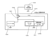
図1の音声記録再生装置1000は、音声記録用マイクロフォン1001、音声出力用スピーカ1002、記録媒体駆動部や録再ヘッド等を含むデッキ部1003等を有し、電池ホルダ1100に装着された所定の規格に適合する定格数(図示の場合は6個)の二次電池(ニッケル水素充電電池)110,110の直列接続による定格起電力を、音声の記録再生に係る動作の電源として該当する記録媒体駆動部や回路各部等に供給するようになされた、それ自体は一般的な構成を有するものである。
An audio recording / reproducing
音声記録再生装置1000には、アンテナ1004によって受信されたラジオ放送を復調してスピーカ1002で音声を出力するための本図では表されない受信回路が内部に設けられ、選局用ダイヤル1005を操作することによってチューニングインジケータ1006の指示を目安にして選局操作を行うことができるように構成されたラジオ受信機能部が備えられている。
一方、本発明の給電制御装置1200は、上述の6個の電池(以下、適宜「実電池」という)110,110のうちの何れか一つに替えて電池ホルダ1100に保持されるに適合する形状・寸法を成し得る外装体1210を備えている。
The audio recording / reproducing
On the other hand, the power
この外装体1210内には、外装体1210が上述のように6個の実電池110,110のうちの何れか一つに替えて電池ホルダ1100に保持された状態で、他の電池の起電力の合算値に相応する電圧の供給を受けて該供給された電圧を電池ホルダ1100に装着される定格起電力に相応する出力電圧に変換するコンバータ部1220と、コンバータ部1220の出力を所定の負荷である該当する記録媒体駆動部や回路各部等に供給する給電経路1221に介挿され給電制御信号FCSに応じて給電経路1221を開閉するスイッチ部1230と、スイッチ部1230に供給する給電制御信号FCSを生成する給電制御部1240と、が備えられている。ここで、スイッチ部1230が給電経路1221を開閉する制御には、コンバータ部1220の出力を所定の負荷へ供給する制御、コンバータ部1220の出力の所定の負荷への供給を遮断する制御及びコンバータ部1220の出力の所定の負荷への供給量を定格起電力に相応する出力電圧の範囲内で調整する制御が含まれる(以下、同様)。
In the
図2は、図1における給電制御装置の一実施例を表す回路図である。コンバータ部1220は、その一次側(入力側)は省略されているが、図1におけるように給電制御装置1200に置換された実電池以外の実電池の起電力の合算値に相応する電圧の供給を受けるように設けられ、その二次側(出力側)から、例えば、負荷としての上述のラジオ受信機能部(電池駆動式機器における主機能部に該当する)における受信回路1500に給電するように構成されている。
FIG. 2 is a circuit diagram showing an embodiment of the power supply control device in FIG. The
給電経路1221には給電制御部1240からの給電制御信号FCSに応じて給電経路1221を開閉するスイッチ部1230が介挿されている。尚、給電制御部1240の作動電源はスイッチ部1230を介さずにコンバータ部1220から供給される。
この給電制御部1240の場合、特に、限時動作を行うタイマ回路1241が備えられている。このタイマ回路1241は、例えば給電制御装置1200の外装体1210を部分的に同軸状に相対変位可能に構成してその部分を捻るなどの操作による周方向の回動角の程度に応じた時間を任意に設定可能に構成されている。
A
In the case of the power
従って、給電制御部1240にこのようなタイマ回路1241が備えられた給電制御装置1200が一の実電池に替えて電池ホルダに装着された場合には、音声記録再生装置1000(そのラジオ受信機能部)自体は、実電池のみによって電池駆動される際にはタイマ機能を備えていない簡素な構成のものであったとしても、タイマによる限時動作が行われ得るようになる。
Therefore, when the power
タイマによる限時動作によって、オンタイマ機能を持たせ、または、オフタイマ機能を持たせ、或いはまた、これら双方のタイマ機能を選択的に用い得るように構成してもよいことは勿論である。
以上、図1および図2を参照して、当該電池駆動式機器がラジオ受信機能部を備えた音声記録再生装置1000である例について詳述したが、本発明の給電制御装置を適用するに好適な装置は既述のような音声記録再生装置1000に限定されるものではない。
Of course, the timer may be configured to have an on-timer function, an off-timer function, or alternatively, both timer functions may be selectively used by a time-limited operation by a timer.
As described above, with reference to FIGS. 1 and 2, the example in which the battery-driven device is the audio recording / reproducing
例えば、既述のような音声記録再生装置1000よりも小型に構成され、ラジオ受信機能に特化された仕様の電池駆動式機器や、携帯用情報機器や、照明装置等に本発明の給電制御装置を適用すれば、通常の仕様においてはタイマ機能等を備えていないタイプの機器にも、当初からタイマ機能を備えた仕様の装置の如く用いることが可能になる。
携帯用情報機器に本発明の給電制御装置を適用する場合においては、給電制御装置による給電制御の対象となる負荷は携帯情報機器における主機能部としての通信機能部がこれに該当する。
For example, the power supply control of the present invention is applied to a battery-driven device, a portable information device, a lighting device, or the like that is configured to be smaller than the voice recording / reproducing
When the power supply control device of the present invention is applied to a portable information device, a load that is a target of power supply control by the power supply control device corresponds to a communication function unit as a main function unit in the portable information device.
照明装置に本発明の給電制御装置を適用する場合においては、給電制御装置による給電制御の対象となる負荷は照明装置における主機能部としての光源がこれに該当する。
上述の場合、電池駆動式機器本体側には一切負担をかけずに、上述のような機能の付加を実現できるため、既存の、所謂旧型に属するような電池駆動式機器についても、何等支障なくこのような便宜が図られることになる。
In the case where the power supply control device of the present invention is applied to a lighting device, a load that is a target of power supply control by the power supply control device corresponds to a light source as a main functional unit in the lighting device.
In the above case, since the addition of the functions as described above can be realized without placing any burden on the battery-driven device body side, there is no problem with the existing battery-driven device belonging to the so-called old model. Such convenience will be achieved.
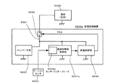
図3は、図1における給電制御装置の他の実施例を表す回路図である。図3において既述の図2との対応部は同一の参照符号を付して示し個々の説明は適宜省略する。
図2の給電制御装置1200における給電制御部1240がタイマ回路1241を備えて、この給電制御装置1200が適用された電池駆動式機器にタイマ機能を付加することを可能ならしめるものであったところ、図3の給電制御装置1200aでは、更に、給電制御部1240aが短距離高速無線ネットワーク・インターフェース1242をも備えて構成されている点が異なる。
短距離高速無線ネットワーク・インターフェース1242は例えばPDAや携帯電話に適用されているブルートゥース或いはIEEE802.11に準拠した方式の通信を可能にする。
FIG. 3 is a circuit diagram showing another embodiment of the power supply control device in FIG. In FIG. 3, corresponding parts to those in FIG. 2 described above are denoted by the same reference numerals, and the description thereof will be omitted as appropriate.
The power
The short-distance high-speed
従って、図3の給電制御部1240aは短距離高速無線ネットワーク・インターフェース1242を通して外部のPDAや携帯電話機からの無線信号(制御信号)を受信し、該受信の内容に応じた給電制御信号FCSを生成しスイッチ部1230を開閉することによって負荷(例えば受信回路)への給電経路1221の断続を行い、結果的に、PDAや携帯電話機によって上述の負荷への給電を遠隔操作することが可能になる。
図3の給電制御装置1200aについても、これが適用されて有効な電池駆動式機器は図1に例示されたような音声記録再生装置1000に限られず、種々のものであり得る点は図2の給電制御装置1200について上述したところと同様である。
3 receives a wireless signal (control signal) from an external PDA or mobile phone through the short-range high-speed
3 is not limited to the voice recording / reproducing
図4は、図1における給電制御装置の更に他の実施例を表す回路図である。図4において既述の図2との対応部は同一の参照符号を付して示し個々の説明は適宜省略する。
図2の給電制御装置1200における給電制御部1240がタイマ回路1241を備えて、この給電制御装置1200が適用された電池駆動式機器にタイマ機能を付加することを可能ならしめるものであったところ、図4の給電制御装置1200bでは、給電制御部1240bが更にモーションセンサ1243をも備えており、給電制御装置1200bの動き(即ち、この給電制御装置1200bが装着された電池駆動式機器本体の動き)に応じた給電制御信号FCSを生成するように構成されている点が異なる。
FIG. 4 is a circuit diagram showing still another embodiment of the power supply control device in FIG. 4 corresponding to those in FIG. 2 described above are denoted by the same reference numerals, and description thereof will be omitted as appropriate.
The power
このような給電制御装置1200bでは、電池ホルダにこの給電制御装置が装着された状態で電池駆動式機器を、例えば所定の運動軌跡を描くように振るなどすることによって、モーションセンサの検出出力に基づいて、負荷への給電を制御することが可能になる。
また、本例の場合では、運動軌跡の描き方に応じてタイマ回路1241に対する時間の設定を任意にないし所定の段階を選択するようにして行うように構成することもできる。
図4の給電制御装置1200bについても、これが適用されて有効な電池駆動式機器は図1に例示されたような音声記録再生装置1000に限られず、種々のものであり得る点は図2の給電制御装置1200について上述したところと同様である。
In such a power supply control device 1200b, based on the detection output of the motion sensor, for example, by shaking the battery-driven device in a state where the power supply control device is mounted on the battery holder so as to draw a predetermined motion trajectory. Thus, the power supply to the load can be controlled.
In the case of this example, the time setting for the
Also for the power supply control device 1200b of FIG. 4, the battery-driven device effective when this is applied is not limited to the voice recording / reproducing
図5は、本発明の給電制御装置を電池駆動式機器本体に装着して、該電池駆動式機器本体に光通信の機能を付与するようにした場合の使用状況の一例を表す概念図である。この場合、本発明の給電制御装置は該当機器本体側に通信機能を付加する回路ユニットである通信回路モジュールとして機能する。
図5において、電池駆動型の照明装置である懐中電灯5000の本体5001内部には、標準的には4本の乾電池を装着する仕様の電池ホルダ5100が設けられている。
この電池ホルダ5100には、後に図面を参照して詳述するように、3個の電池(起電力を生じる実電池)110,110,110と、外観上は、これら実電池を同形同寸法の1個の給電制御装置5200とが装着されている。
FIG. 5 is a conceptual diagram showing an example of a usage situation when the power supply control device of the present invention is attached to a battery-driven device body and the battery-driven device body is provided with an optical communication function. . In this case, the power supply control device of the present invention functions as a communication circuit module which is a circuit unit that adds a communication function to the corresponding device main body.
In FIG. 5, a
In this
懐中電灯5000の本体5001の上部には前後方向に延長されて把持部5002が形成され、その前端近傍の適所に手動電源スイッチ5003が設けられている。
図示されない高輝度LED等の光源から発せられた照明光は透明体でなる保護部材の光出射面5004から外部前方に所定の指向性をもって投射される。
この懐中電灯5000は、電池ホルダ5100内に装着された給電制御装置5200の上述の通信回路モジュールとしての機能によって光源への給電を制御し、照明光を所定のコード体系に準拠した形態で点滅もしくは明滅させることによって照明光通信を行うことが可能である。
A
Illumination light emitted from a light source such as a high-intensity LED (not shown) is projected with a predetermined directivity from the
The
この照明光通信における被送信情報は、図5の例では、特定の仕様の携帯電話機をその一例とする携帯情報端末装置5500から、短距離高速無線通信である、例えば、ブルートゥースに準拠した信号BTに担われる形で懐中電灯5000の本体5001内の給電制御装置5200に供給される。
携帯情報端末装置5500は、ファンクションキー5501、文字入力キー5502、および、ディスプレイ5503を有し、ブルートゥースの信号BTによって短距離高速無線通信を行い得るように構成されており、この点は公知のこの種の装置と同様である。
In the example of FIG. 5, the transmitted information in the illumination light communication is a short-distance high-speed wireless communication from the portable
The portable
被送信情報の発信元のユーザは、携帯情報端末装置5500からキー入力操作などによって被送信情報をブルートゥースの信号BTにのせて通信回路モジュールとして機能する給電制御装置5200に供給する。
懐中電灯5000の本体5001側では、上述のようにして供給された被送信情報に応じて給電制御装置5200の作用によって光出射面5004から投射する照明光に変調を与えるため、照明光による被送信情報の送信が行われる。
The user who is the source of the transmitted information supplies the transmitted information from the portable
On the
一方、このように照明光による光通信の受信側では、上述の携帯情報端末装置5500と同様のものであり得る携帯情報端末装置5600のカメラ5601によって、その撮像視野SV内に懐中電灯5000側からの照明光を動画像として捉え、それ自体は公知の照明光信号解読機能によって動画像として捉えた照明光の信号から被送信情報を復調する。
以上、図5を参照して説明した技術によれば、携帯情報端末装置のディスプレイ部の発光に比して格段に光の到達距離が長い照明装置である懐中電灯5000から投射される照明光に被送信情報に応じた変調を与えることにより照明光通信を行うことが可能になる。
また、電池ホルダに保持される給電制御装置が照明光を被送信情報に応じて変調する通信回路モジュールとして機能し、照明光(従って、照明用の光源自体)を利用して光通信を行うため、電池を交換する手軽さで、エンドユーザが任意に光通信における送信機能を電池駆動型の照明装置に付加することができる。
On the other hand, on the receiving side of the optical communication using illumination light as described above, the
As described above, according to the technology described with reference to FIG. 5, the illumination light projected from the
In addition, the power supply control device held by the battery holder functions as a communication circuit module that modulates illumination light according to transmitted information, and performs optical communication using illumination light (and thus the illumination light source itself). The end user can arbitrarily add a transmission function in optical communication to the battery-driven lighting device by simply replacing the battery.
図6は、本発明の給電制御装置を電池駆動式機器本体に装着して、該電池駆動式機器本体に光通信の機能を付与するようにした場合の使用状況の他の例を表す概念図である。この場合も、本発明の給電制御装置は該当機器本体側に通信機能を付加する回路ユニットである通信回路モジュールとして機能する。
図6において、電池駆動型の照明装置であるLED式ランタン6000の本体6001内部には、標準的には4本の乾電池を装着する仕様の電池ホルダ6100が設けられている。
FIG. 6 is a conceptual diagram showing another example of a usage situation when the power supply control device of the present invention is mounted on a battery-driven device body and the battery-driven device body is provided with an optical communication function. It is. Also in this case, the power supply control device of the present invention functions as a communication circuit module that is a circuit unit that adds a communication function to the corresponding device main body.
In FIG. 6, a
この電池ホルダ6100には、後に図面を参照して詳述するように、3個の電池(起電力を生じる実電池)110,110,110と、外観上は、これら実電池を同形同寸法の1個の給電制御装置6200とが装着されている。
LED式ランタン6000の本体6001の上部には水平部分が適度に太く形成された把持部6002が設けられ、一方、透明なカバー6003の下方前面の適所に手動電源スイッチ6004が設けられている。
高輝度LEDの光源6005から発せられた照明光は透明なカバー6003から全周方向に特定の指向性を持たずに投射される。
In this
On the upper part of the
Illumination light emitted from the
このLED式ランタン6000は、電池ホルダ6100内に装着された給電制御装置6200内に設けられた上述の通信回路モジュールとしての機能によって光源への給電を制御し、照明光を所定のコード体系に準拠した形態で点滅もしくは明滅させることによって照明光通信を行うことが可能である。
上述の照明光通信における被送信情報は、図6の例では、通信回路モジュール(即ち、給電制御装置6200)に備えられた後述するセンサ・インターフェースによって受信した、例えば、温度、圧力、流量、等々の所定の物象の状態の量の検出値である。
This LED-
In the example of FIG. 6, the transmitted information in the above-described illumination light communication is received by a sensor interface (described later) provided in the communication circuit module (that is, the power supply control device 6200), for example, temperature, pressure, flow rate, and the like. This is a detected value of the amount of the state of the predetermined object.
このような物象の状態の量が本通信回路モジュール6200の作用により、照明装置であるLED式ランタン6000から照明光通信によって通信相手に伝送される。
特に、図6の場合は、センサ・インターフェースによって温度センサである測温抵抗体6300によって検出される水槽6400の水温が受信されるように構成されている。
LED式ランタン6000側では、上述のようにして供給された被送信情報である水槽6400の水温データに応じて通信回路モジュール6200の作用によって高輝度LEDの光源6005から投射する照明光に変調を与えるため、照明光による被送信情報(水温の検出値)の送信が行われる。
The amount of such a physical state is transmitted from the
In particular, in the case of FIG. 6, the water temperature of the
On the
一方、受信側では、図5の携帯情報端末装置5600と同様のものであり得る携帯情報端末装置6600のカメラ6601によって、その撮像視野SV内にLED式ランタン6000側(その高輝度LEDの光源6005)からの照明光を動画像として捉え、それ自体は公知の照明光信号解読機能によって動画像として捉えた照明光の信号から被送信情報を復調する。
On the other hand, on the receiving side, the
以上、図6を参照して説明した技術によれば、携帯情報端末装置のディスプレイ部の発光に比して格段に光の到達距離が長い照明装置であるLED式ランタン6000から投射される照明光に被送信情報に応じた変調を与えることにより照明光通信が可能になる。
また、電池ホルダに保持される給電制御装置が照明光を被送信情報に応じて変調する通信回路モジュールとして機能し、照明光(従って、照明用の光源自体)を利用して光通信を行うため、電池を交換する手軽さで、エンドユーザが任意に光通信における送信機能を電池駆動型の照明装置に付加することができる。
As described above, according to the technology described with reference to FIG. 6, the illumination light projected from the
In addition, the power supply control device held by the battery holder functions as a communication circuit module that modulates illumination light according to transmitted information, and performs optical communication using illumination light (and thus the illumination light source itself). The end user can arbitrarily add a transmission function in optical communication to the battery-driven lighting device by simply replacing the battery.
図7および図8は、図5を参照して説明した給電制御装置5200の実施例を表す回路図である。
図7において、給電制御装置5200は、コンバータ部5220、被送信情報を受信するアンテナ回路5242を有する被送信情報受信部5241、被送信情報受信部5241で受信された被送信情報に応じて給電制御信号FCSを生成し、照明光に変調を与えるように光源への給電を制御する給電制御部5240、および、コンバータ部5220から負荷としての光源5235への給電経路5221に介挿され給電制御部5240から出力される給電制御信号FCSによって給電の断続を行うスイッチ部5230とを含んで構成されている。
7 and 8 are circuit diagrams showing an embodiment of the power
In FIG. 7, the power
一方、図8における、給電制御装置5200aは、図7の給電制御装置5200と略同様に、コンバータ部5220、被送信情報受信部5241a、給電制御部5240、および、給電経路5221に介挿されたスイッチ部5230とを含んで構成されている。
スイッチ部5230の開閉によって負荷としての光源3235への給電の断続が行われる点も図7の例と同様であるが、図8の給電制御装置5200aでは、被送信情報受信部5241aが、特に、ブルートゥース・インターフェースのような短距離高速無線ネットワーク・インターフェース5242aを備えている点を特徴としている。
On the other hand, the power supply control device 5200a in FIG. 8 is inserted into the
7 is the same as the example of FIG. 7 in that the power supply to the light source 3235 as a load is interrupted by opening and closing the
次に、図8に示す給電制御装置5200aを適用した場合の図5に示す懐中電灯5000の使用状況の一例を説明する。図9は、図8に示す給電制御装置の給電制御部が行う処理を示すフローチャートである。
この懐中電灯5000は、電池ホルダ5100内に装着された給電制御装置5200aの通信回路モジュールとしての機能によって光源への給電を制御し、照明光を所定のコート体系に準拠した形態で点滅もしくは明滅させることによって照明光通信を行うことが可能である。
Next, an example of the usage state of the
This
この照明光通信における被送信情報は、携帯情報端末装置5500から、短距離高速無線通信である、例えば、ブルートゥースに準拠した信号BTに担われる形で懐中電灯5000の本体5001内の給電制御装置5200aに供給される。
被送信情報の発信元のユーザは、携帯情報端末装置5500からキー入力操作などによって被送信情報をブルートゥースの信号BTにのせて給電制御装置5200aに供給する。
The transmitted information in the illumination light communication is short-distance high-speed wireless communication from the portable
The user who is the transmission source of the transmitted information supplies the transmitted information on the Bluetooth signal BT to the power supply control device 5200a from the portable
この場合、携帯情報端末装置5500は、ユーザにより入力された被送信情報のコード化を行い、コード化された情報に基づいて信号BTを生成する。そして、携帯情報端末装置5500は、生成した信号BTを給電制御装置5200aに送信する。
給電制御装置5200aは、携帯情報端末装置5500が送信した信号BTを、被送信情報受信部5241aによって受信する。この場合、被送信情報受信部5241aは、携帯情報端末装置5500が送信した信号BTを、短距離高速無線ネットワーク・インターフェース5242aを通して受信する。
In this case, portable
The power supply control device 5200a receives the signal BT transmitted from the portable
そして、懐中電灯5000の給電制御装置5200aは、携帯情報端末装置5500からの信号BTを受信すると、図9に示す照明光制御処理を実行する。
すなわち、給電制御装置5200aの被送信情報受信部5241aが信号BTを受信すると、まず、ステップS901に移行する。
ステップS901では、被送信情報受信部5241aが、受信した信号BTを給電制御部5240に入力し、その後、ステップS902に移行する。
When the power supply control device 5200a of the
That is, when the transmitted
In step S901, the transmitted
ステップS902では、給電制御部5240が、入力された信号BTに基づいて光源の点滅パターンを生成し、その後、ステップS903に移行する。この場合、光源の点滅パターンは、予め定められた所定のプロトコルにしたがって生成される。
ステップS903では、給電制御部5240が、生成された点滅パターンに基づいて給電制御信号FCSを生成し、その後、ステップS904に移行する。
In step S902, the power
In step S903, the power
ステップS904では、給電制御部5240が、生成した給電制御信号FCSをスイッチ部5230に送信し、その後、ステップS905に移行する。
ステップS905では、スイッチ部5230が、給電制御信号FCSに応じて光源5235への給電を制御し、その後、照明光制御処理を終了する。
上記照明光制御処理によって、被送信情報に応じて変調が与えられた照明光が、光通信の送信側である懐中電灯5000の光出射面5004から、光通信の受信側である携帯情報端末装置5600に向かって投射される。
In step S904, the power
In step S905, the
Illumination light modulated according to the transmitted information by the illumination light control process from the
携帯情報端末装置5600は、懐中電灯5000から投射された照明光を、カメラ5601によって受信する。この場合、携帯情報端末装置5600は、カメラ5601によって、その撮像視野SV内に懐中電灯5000側からの照明光を動画像として捉える。
そして、携帯情報端末装置5600は、懐中電灯5000からの照明光を受信すると、それ自体は公知の照明光信号解読機能によって動画像として捉えた照明光の信号から被送信情報を復調する。この場合、携帯情報端末装置5600は、上述した予め定められた所定のプロトコルにしたがって照明光の信号から被送信情報を復調する。
The portable
Then, when receiving the illumination light from the
そして、携帯情報端末装置5600は、復調した被送信情報をディスプレイ部等に表示する。これにより、携帯情報端末装置5600のユーザは、被送信情報を確認することができる。
以上、給電制御装置5200aを備えた懐中電灯5000によれば、携帯情報端末装置のディスプレイ部の発光に比して格段に光の到達距離が長い照明装置である懐中電灯5000から投射される照明光に被送信情報に応じた変調を与えることにより照明光通信を行うことが可能になる。
Then, portable
As described above, according to the
ここで、給電制御装置5200aでは、該給電制御装置5200aを識別するためのID情報を給電制御部5240に格納する構成を採用しても構わない。
この場合、照明光通信における被送信情報は、携帯情報端末装置5500から入力された情報及びID情報である。そして、給電制御装置5200aは、照明光によって被送信情報である携帯情報端末装置5500から入力された情報及びID情報を光通信の受信側である携帯情報端末装置5600に送信する。
Here, the power supply control device 5200a may adopt a configuration in which ID information for identifying the power supply control device 5200a is stored in the power
In this case, the transmitted information in the illumination light communication is information input from the portable
すなわち、給電制御装置5200aは、被送信情報受信部5241aが信号BTを受信した際に実行される照明光制御処理において、入力された信号BT及び給電制御部5240に格納されているID情報を送信するための光源の点滅パターンを生成する。この場合、光源の点滅パターンは、上述した予め定められた所定のプロトコルにしたがって生成される。そして、給電制御装置5200aは、生成された点滅パターンに基づいて給電制御信号FCSを生成し、生成した給電制御信号FCSに応じて光源5235への給電を制御する。
That is, the power supply control device 5200a transmits the input signal BT and the ID information stored in the power
これにより、光通信の受信側である携帯情報端末装置5600では、携帯情報端末装置5500から入力された情報をID情報に基づいて管理することが可能となる。例えば、給電制御装置5200aが装着された懐中電灯5000が複数使用されている環境下においても、光通信の受信側である携帯情報端末装置5600は、それぞれの懐中電灯5000から送信された情報(携帯情報端末装置5500から入力された情報)をID情報に基づいて管理することが可能となる。
As a result, the portable
一方、図10は、図6を参照して説明した給電制御装置6200の実施例を表す回路図である。
図10において、給電制御装置6200は、コンバータ部6220、被送信情報を受信する被送信情報受信部6242、被送信情報受信部6241で受信された被送信情報に応じて給電制御信号FCSを生成し、照明光に変調を与えるように光源への給電を制御する給電制御部6240、および、コンバータ部6220から負荷としての光源6235への給電経路6221に介挿され給電制御部6240から出力される給電制御信号FCSによって給電の断続を行うスイッチ部6230とを含んで構成されている。
On the other hand, FIG. 10 is a circuit diagram showing an embodiment of the power
In FIG. 10, the power
上述のような構成において、図10の被送信情報受信部6241では、特に、例えば、温度、圧力、流量、等々の所定の物象の状態の量を検出するセンサによって取得された情報を受けるセンサ・インターフェース6242を備えている点を特徴としている。
このセンサ・インターフェース6242には、センサとして、より具体的には、図6のような応用例の場合、温度センサである測温抵抗体6300からの水温の検出値(水温に対応する抵抗値)が供給される。
In the configuration as described above, the transmitted
In the
即ち、図10の給電制御装置6200を適用すれば、被送信情報たる温度、圧力、流量、等々の所定の物象の状態の量を表すデータを照明光による光通信によって送信することができる。
次に、図10に示す給電制御装置6200を適用した場合の図6に示すLED式ランタン6000の使用状況の一例を説明する。図11は、図10に示す給電制御装置の給電制御部が行う処理を示すフローチャートである。
That is, if the power
Next, an example of the usage state of the
このLED式ランタン6000は、電池ホルダ6100内に装着された給電制御装置6200の通信回路モジュールとしての機能によって光源への給電を制御し、照明光を所定のコート体系に準拠した形態で点滅もしくは明滅させることによって照明光通信を行うことが可能である。
この照明光通信における被送信情報は、温度センサである測温抵抗体6300によって検出される水槽6400の水温データである。そして、測温抵抗体6300は、検出した水槽6400の水温を電気信号(以下、測定信号という)にのせて給電制御装置6200に送信する。
The
The transmitted information in the illumination light communication is water temperature data of the
給電制御装置6200は、測温抵抗体6300から送信される測定信号を、被送信情報受信部6241によって受信する。この場合、被送信情報受信部6241は、測温抵抗体6300から送信される測定信号を、センサ・インターフェース6242を通して受信する。
そして、LED式ランタン6000の給電制御装置6200は、測温抵抗体6300から送信される測定信号を受信すると、図11に示す照明光制御処理を実行する。
The power
And the electric power
すなわち、給電制御装置6200の被送信情報受信部6241が測定信号を受信すると、まず、ステップS1101に移行する。
ステップS1101では、被送信情報受信部6241が、受信した測定信号を給電制御部6240に入力し、その後、ステップS1102に移行する。
ステップS1102では、給電制御部6240が、入力された測定信号に基づいて光源の点滅パターンを生成し、その後、ステップS1103に移行する。この場合、光源の点滅パターンは、予め定められた所定のプロトコルにしたがって生成される。
That is, when the transmitted
In step S1101, the transmitted
In step S1102, the power
ステップS1103では、給電制御部6240が、生成された点滅パターンに基づいて給電制御信号FCSを生成し、その後、ステップS1104に移行する。
ステップS1104では、給電制御部6240が、生成した給電制御信号FCSをスイッチ部6230に送信し、その後、ステップS1105に移行する。
ステップS1105では、スイッチ部6230が、給電制御信号FCSに応じて光源6235への給電を制御し、その後、照明光制御処理を終了する。
In step S1103, the power
In step S1104, the power
In step S1105, the
上記照明光制御処理によって、被送信情報である水温データに応じて変調が与えられた照明光が、光通信の送信側であるLED式ランタン6000の光源6005から、光通信の受信側である携帯情報端末装置6600に向かって投射される。
携帯情報端末装置6600は、LED式ランタン6000から投射された照明光を、カメラ6601によって受信する。この場合、携帯情報端末装置6600は、カメラ6601によって、その撮像視野SV内にLED式ランタン6000側(光源6005)からの照明光を動画像として捉える。
Illumination light modulated according to the water temperature data that is transmitted information by the illumination light control process is transmitted from the
The portable
そして、携帯情報端末装置6600は、LED式ランタン6000からの照明光を受信すると、それ自体は公知の照明光信号解読機能によって動画像として捉えた照明光の信号から被送信情報を復調する。この場合、携帯情報端末装置6600は、上述した予め定められた所定のプロトコルにしたがって照明光の信号から被送信情報を復調する。
そして、携帯情報端末装置6600は、復調した被送信情報をディスプレイ部等に表示する。これにより、携帯情報端末装置6600のユーザは、被送信情報である水温データを確認することができる。
When receiving the illumination light from the
Then, portable
以上、給電制御装置6200を備えたLED式ランタン6000によれば、携帯情報端末装置のディスプレイ部の発光に比して格段に光の到達距離が長い照明装置であるLED式ランタン6000から投射される照明光に被送信情報に応じた変調を与えることにより照明光通信を行うことが可能になる。
ここで、給電制御装置6200では、該給電制御装置6200を識別するためのID情報を給電制御部6240に格納する構成を採用しても構わない。
As described above, according to the
Here, the power
この場合、照明光通信における被送信情報は、温度センサである測温抵抗体6300によって検出される水槽6400の水温データ及びID情報である。そして、給電制御装置6200は、照明光によって被送信情報である水温データ及びID情報を光通信の受信側である携帯情報端末装置6600に送信する。
すなわち、給電制御装置6200は、被送信情報受信部6241が測定信号を受信した際に実行される照明光制御処理において、入力された測定信号及び給電制御部6240に格納されているID情報を送信するための光源の点滅パターンを生成する。この場合、光源の点滅パターンは、上述した予め定められた所定のプロトコルにしたがって生成される。そして、給電制御装置6200は、生成された点滅パターンに基づいて給電制御信号FCSを生成し、生成した給電制御信号FCSに応じて光源6235への給電を制御する。
In this case, the transmitted information in the illumination light communication is the water temperature data and ID information of the
That is, the power
これにより、光通信の受信側である携帯情報端末装置6600では、水温データをID情報に基づいて管理することが可能となる。例えば、池の複数の水温測定箇所のそれぞれに給電制御装置6200が装着されたLED式ランタン6000が設置されている場合に、光通信の受信側である携帯情報端末装置6600は、それぞれのLED式ランタン6000から送信される水温データをID情報に基づいて管理することが可能となる。すなわち、一つの携帯情報端末装置6600で、複数の水温測定箇所のそれぞれの水温データを管理することが可能となる。
As a result, the portable
また、給電制御装置6200では、該給電制御装置6200の位置を検出するための位置検出センサを備える構成を採用しても構わない。この場合、位置検出センサとしては、GPSセンサ、ジャイロセンサ等が該当する。
この場合、照明光通信における被送信情報は、温度センサである測温抵抗体6300によって検出される水槽6400の水温データ及び位置検出センサによって検出される給電制御装置6200を装着したLED式ランタン6000の位置情報である。そして、給電制御装置6200は、照明光によって被送信情報である水温データ及び位置情報を光通信の受信側である携帯情報端末装置6600に送信する。
Further, the power
In this case, the transmitted information in the illumination light communication includes the water temperature data of the
すなわち、給電制御装置6200は、被送信情報受信部6241が測定信号を受信した際に実行される照明光制御処理において、入力された測定信号及び位置検出センサで検出した位置情報を送信するための光源の点滅パターンを生成する。この場合、光源の点滅パターンは、上述した予め定められた所定のプロトコルにしたがって生成される。そして、給電制御装置6200は、生成された点滅パターンに基づいて給電制御信号FCSを生成し、生成した給電制御信号FCSに応じて光源6235への給電を制御する。
これにより、光通信の受信側である携帯情報端末装置6600では、水温データを位置情報に基づいて管理することが可能となる。例えば、一つのLED式ランタン6000によって池の複数箇所の水温を測定した場合に、それぞれの測定箇所の水温データを位置情報に基づいて管理することが可能となる。
That is, the power
As a result, the portable
図12は、給電制御装置の更に他の実施例を表す回路図である。
図12において既述の図10との対応部は同一の参照符号を付して示し個々の説明は適宜省略する。
給電制御装置6200aには、図10の給電制御装置6200と同様に、コンバータ部6220、被送信情報受信部6241a、給電制御部6240、および、負荷としての光源6235への給電経路6221に介挿されたスイッチ部6230を含んで構成されている。
FIG. 12 is a circuit diagram illustrating still another embodiment of the power supply control device.
In FIG. 12, the parts corresponding to those of FIG. 10 described above are denoted by the same reference numerals, and the description thereof will be omitted as appropriate.
Similarly to the power
この給電制御装置6200aが図5における懐中電灯5000の電池ホルダ5100に既述の給電制御装置5200に替えて装着された場合には、スイッチ部6230の開閉によって図5の懐中電灯5000の光源への給電の断続によって結果的に光通信が行われる点は図7の例と同様である。
しかしながら、図12の実施例では被送信情報受信部6241aが、特に、例えば、ジャイロセンサのようなモーションセンサ6350によって取得される情報を受けるセンサ・インターフェース6242aを備えている点を特徴としている。
When the power supply control device 6200a is attached to the
However, the embodiment of FIG. 12 is characterized in that the transmitted
このセンサ・インターフェース6242aには、モーションセンサによって取得された物体(例えば、この給電制御装置6200aを含む照明装置としての懐中電灯5000自体)の動きに関する検出値が被送信情報としてセンサ・インターフェースから入力される。
従って、送信元のユーザが、PDA等の他の装置の使用を俟つことなく、懐中電灯5000を例えば特定の規約に従って空中で一定の軌跡を描くように振る等して、特定の被送信情報を被送信情報受信部6241aに認識させ、該認識させた情報に応じて給電制御部6200aの作動によって光源光を点滅させ、この点滅による照明光通信によって情報を送信することが可能になる。
即ち、所定の態様で振ると光源が点灯し、例えば、懐中電灯5000を反時計方向に回すと、データAを表す光信号が送信されるといった用い方が可能になる。
The
Therefore, the user who is the transmission source does not hesitate to use another device such as a PDA, and shakes the
That is, when the light source is shaken in a predetermined manner, the light source is turned on. For example, when the
次に、図12に示す給電制御装置6200aを適用した場合の図5に示す懐中電灯5000の使用状況の一例を説明する。図13は、図12に示す給電制御装置の給電制御部が行う処理を示すフローチャートである。
この懐中電灯5000は、電池ホルダ5100内に装着された給電制御装置6200aの通信回路モジュールとしての機能によって光源への給電を制御し、照明光を所定のコート体系に準拠した形態で点滅もしくは明滅させることによって照明光通信を行うことが可能である。
この照明光通信における被送信情報は、給電制御装置6200aが装着された懐中電灯5000自体の動きの態様に対応付けられた情報である。
Next, an example of the usage state of the
This
The transmitted information in the illumination light communication is information associated with the movement mode of the
すなわち、懐中電灯5000のユーザは、懐中電灯5000自体を所定の態様で動かすことによって被送信情報を給電制御装置6200aに入力する。ここで、懐中電灯5000の動きの態様とこれに対応する被送信情報との関係は予め定められている。例えば、懐中電灯5000を時計回りに回転させた場合にはデータAが被送信情報となり、懐中電灯5000を反時計回りに回転させた場合にはデータBが被送信情報となるように定められている。
That is, the user of the
モーションセンサ6350は、給電制御装置6200aが装着された懐中電灯5000自体の動きに関する検出値を電気信号(以下、検出信号という)にのせて給電制御装置6200aに送信する。
給電制御装置6200aは、モーションセンサ6350から送信される検出信号を、被送信情報受信部6241aによって受信する。この場合、被送信情報受信部6241aは、モーションセンサ6350から送信される検出信号を、センサ・インターフェース6242aを通して受信する。
The
The power feeding control device 6200a receives the detection signal transmitted from the
そして、懐中電灯5000の給電制御装置6200aは、モーションセンサ6350から送信される検出信号を受信すると、図13に示す照明光制御処理を実行する。
すなわち、給電制御装置6200aの被送信情報受信部6241aが検出信号を受信すると、まず、ステップS1301に移行する。
ステップS1301では、被送信情報受信部6241aが、受信した検出信号を給電制御部6240に入力し、その後、ステップS1302に移行する。
When the power supply control device 6200a of the
That is, when the transmitted
In step S1301, the transmitted
ステップS1302では、給電制御部6240が、入力された検出信号に基づいて懐中電灯5000動きの態様を検出し、その後、ステップS1303に移行する。この場合、懐中電灯5000の動きの態様の検出は、入力された検出信号の変化に基づいて所定のプロトコルにしたがって検出される。
ステップS1303では、給電制御部6240が、検出した懐中電灯5000動きの態様に基づいて光源の点滅パターンを生成し、その後、ステップS1304に移行する。この場合、給電制御部6240は、懐中電灯5000動きの態様と光源の点滅パターンとの対応関係を示すコマンドテーブルに基づいて光源の点滅パターンを生成する。
In step S1302, the power
In step S1303, the power
ステップS1304では、給電制御部6240が、生成された点滅パターンに基づいて給電制御信号FCSを生成し、その後、ステップS1305に移行する。
ステップS1305では、給電制御部6240が、生成した給電制御信号FCSをスイッチ部6230に送信し、その後、ステップS1306に移行する。
ステップS1306では、スイッチ部6230が、給電制御信号FCSに応じて光源6235への給電を制御し、その後、照明光制御処理を終了する。
In step S1304, the power
In step S1305, the power
In step S1306, the
上記照明光制御処理によって、被送信情報に応じて変調が与えられた照明光が、光通信の送信側である懐中電灯5000の光出射面5004から、光通信の受信側である携帯情報端末装置5600に向かって投射される。
携帯情報端末装置5600は、懐中電灯5000から投射された照明光を、カメラ5601によって受信する。この場合、携帯情報端末装置5600は、カメラ5601によって、その撮像視野SV内に懐中電灯5000側からの照明光を動画像として捉える。
Illumination light modulated according to the transmitted information by the illumination light control process from the
The portable
そして、携帯情報端末装置5600は、懐中電灯5000からの照明光を受信すると、それ自体は公知の照明光信号解読機能によって動画像として捉えた照明光の信号から被送信情報を復調する。この場合、携帯情報端末装置5600は、上述した予め定められた所定のプロトコルにしたがって照明光の信号から被送信情報を復調する。
そして、携帯情報端末装置5600は、復調した被送信情報をディスプレイ部等に表示する。これにより、携帯情報端末装置5600のユーザは、被送信情報を確認することができる。
Then, when receiving the illumination light from the
Then, portable
以上、給電制御装置6200aを備えた懐中電灯5000によれば、携帯情報端末装置のディスプレイ部の発光に比して格段に光の到達距離が長い照明装置である懐中電灯5000から投射される照明光に被送信情報に応じた変調を与えることにより照明光通信を行うことが可能になる。
ここで、給電制御装置6200aでは、該給電制御装置6200aを識別するためのID情報を給電制御部6240に格納する構成を採用しても構わない。
この場合、照明光通信における被送信情報は、懐中電灯5000自体の動きの態様に対応付けられた情報及びID情報である。そして、給電制御装置6200aは、照明光によって被送信情報である懐中電灯5000自体の動きの態様に対応付けられた情報及びID情報を光通信の受信側である携帯情報端末装置5600に送信する。
As described above, according to the
Here, the power supply control device 6200a may adopt a configuration in which ID information for identifying the power supply control device 6200a is stored in the power
In this case, the transmitted information in the illumination light communication is information and ID information associated with the movement mode of the
すなわち、給電制御装置6200aは、被送信情報受信部6241aが検出信号を受信した際に実行される照明光制御処理において、入力された検出信号に対応する情報及び給電制御部5240に格納されているID情報を送信するための光源の点滅パターンを生成する。そして、給電制御装置6200aは、生成された点滅パターンに基づいて給電制御信号FCSを生成し、生成した給電制御信号FCSに応じて光源6235への給電を制御する。
これにより、光通信の受信側である携帯情報端末装置5600では、懐中電灯5000自体の動きの態様に対応付けられた情報をID情報に基づいて管理することが可能となる。
That is, the power supply control device 6200a is stored in the information corresponding to the input detection signal and the power
As a result, the portable
図14は、本発明の給電制御装置における電源回路としての機能を説明するための図である。
図14では、照明装置としての図5のLED式懐中電灯5000や図6のLED式ランタン6000におけるように、4本の電池を並置して装着する仕様の電池ホルダに本発明の給電制御装置120を装着した様子が表されている。
FIG. 14 is a diagram for explaining a function as a power supply circuit in the power supply control device of the present invention.
In FIG. 14, the power
一方、電池ホルダ側については公知のものと同様でありその構造体部分は図示を省略して接触子のみ示してある。この電池ホルダは通常の如く電池を直列接続して用いる形式のものであり、正極側の出力端子となる第1の接触子11、隣接する電池の負極と正極とを結ぶために両者が接続された負極側の第2の接触子12、第4の接触子12a、第6の接触子12b、および、正極側の第3の接触子13、第5の接触子13a、第7の接触子13b、ならびに、負極側の出力端子となる第8の接触子14が設けられている。
On the other hand, the battery holder side is the same as a known one, and the structure portion is not shown and only the contact is shown. This battery holder is of a type that uses batteries connected in series as usual, and the
この例では、第3の接触子13および第8の接触子14間に通常のニッケル水素充電電池(「NiMH」と表記)110が直列に3個接続されて装着され、更に、第1の接触子11および第2の接触子12間に、本発明の実施の形態としての給電制御装置120が装着されている。
また、図14では、給電制御装置120について、コンバータ部122以外の既述のような給電制御部およびスイッチ部については、付加機能部として一括して表されている。
In this example, three ordinary nickel metal hydride rechargeable batteries (indicated as “NiMH”) 110 are connected in series between the
Further, in FIG. 14, regarding the power
即ち、この給電制御装置120の外装体121内には電池の起電力(3個の実電池の起電力の合算値)に相応する電圧の供給を受けて該供給された電圧を定格起電力に相応する出力電圧に変換するコンバータ部122が設けられている。
また、図示のように外装体121内の実装スペース125における一の部分を占めるように実装されたコンバータ部122と共に実装スペース125における他の部分に実装されるようにして既述のような給電制御部およびスイッチ部を含む付加機能部126が設けられている。
尚、この図14および以下に参照する各図において、「A」「B」「G」の表記は、入出力の等価回路との対照を容易にするために便宜上付したものである。
That is, a voltage corresponding to the electromotive force of the battery (the sum of the electromotive forces of the three actual batteries) is supplied to the
In addition, as shown in the figure, the power supply control as described above is performed so that the
In FIG. 14 and the drawings referred to below, the notations “A”, “B”, and “G” are added for the sake of convenience in order to facilitate comparison with the input / output equivalent circuit.
図15は、図14中の給電制御装置120に関する入出力の関係を表す等価回路の図である。尚、この等価回路では付加機能部126として一括して表された給電制御部およびスイッチ部におけるスイッチ部がオン状態を維持していると想定しており、従って、付加機能部126は単に一本の導線の如く表記されている。
図14、および、図15を参照して理解されるように、給電制御装置120の出力端(正極側)をA、負極側をBとすると、この負極側Bがニッケル水素充電電池110の正極側と同電位である。
FIG. 15 is an equivalent circuit diagram showing the input / output relationship for the power
As can be understood with reference to FIGS. 14 and 15, when the output end (positive electrode side) of the power
給電制御装置120内のコンバータ部122の動作用電源については、このコンバータ部122の正極側入力(即ち、給電制御装置120の負極側B)にニッケル水素充電電池110の正極側が接触してこのニッケル水素充電電池110からその起電力が印加され、このコンバータ部122の負極側入力は電源供給用導線123を通してニッケル水素充電電池110の負極側(即ち、図7では電池ホルダの第8の接触子14)に接続されている。
Regarding the power supply for operation of the
電源供給用導線123のニッケル水素充電電池110の負極側への接続は、この電源供給用導線123が外装体120から外部に導出されたその端部に電池ホルダの所定の接触子との電気的接触を得るために設けられた接触導体部130によって確実になされる。
上述の給電制御装置はこのように、4本の電池を直列にして用いる仕様の電池ホルダに装着される電池のうちの1本の電池に替えてこの電池ホルダに装着するようにして用い得る。
以上から容易に理解されるとおり、本発明の給電制御装置は、電池を、2本、3本、4本、5本、または、6本(図1の場合がこれに該当)直列に用いる型式の電池ホルダに対して、それらに装着される電池のうちの少なくとも1本のものに替えて、その電池ホルダに装着させるようにして用い得る。
The connection of the
In this way, the power supply control device described above can be used in such a manner that it is attached to this battery holder instead of one of the batteries attached to the battery holder of the specification that uses four batteries in series.
As can be easily understood from the above, the power supply control device of the present invention uses two, three, four, five, or six batteries in series (this corresponds to the case of FIG. 1). The battery holder can be used by being attached to the battery holder instead of at least one of the batteries attached to the battery holder.
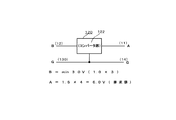
電池を2本直列に用いる型式の電池ホルダに対して適用する場合については、下限値の入力電圧としてニッケル水素充電電池110の略終止電圧である1.0Vが供給されているときに、同型式のニッケル水素充電電池2個を直列に用いたときの定格の起電力である略3.0Vの出力電圧を生起するように構成され、電池を3本直列に用いる型式の電池ホルダに対して適用する場合については、各電池の起電力が最低値として1.0V付近まで低下してきても2本の直列起電力2.0Vを受けて4.5Vの出力を得るように、以下同様に、電池を4本直列に用いる型式では3本の直列起電力3.0Vを受けて6.0Vの出力を得るように、電池を5本直列に用いる型式では4本の直列起電力4.0Vを受けて7.5Vの出力を得るように、電池を6本直列に用いる型式(図1の場合がこれに該当)では5本の直列起電力5.0Vを受けて9.0Vの出力を得るように、コンバータ部122構成される。
When applied to a battery holder of a type in which two batteries are used in series, when 1.0 V, which is a substantially final voltage of the nickel metal hydride
以上に説明した給電制御装置は、実電池としてのニッケル水素充電電池と組み合わせて用いる場合、次に述べるような種々の利点がある。即ち、現行のアルカリマンガン電池で動作する仕様の電子機器にニッケル水素電池を適合させることが可能となる。この場合、漏液の虞がなくなり、充電によって繰り返し使用可能であるため自然保護の観点からも推奨されるものとなる。 The power supply control device described above has various advantages as described below when used in combination with a nickel metal hydride rechargeable battery as an actual battery. That is, the nickel metal hydride battery can be adapted to an electronic device having a specification that operates with the current alkaline manganese battery. In this case, there is no risk of leakage, and it can be used repeatedly by charging, so it is recommended from the viewpoint of nature protection.
また、高容量(低電圧化)ニッケル水素電池の能力を十分に活用することができる。即ち、ニッケル水素電池を現行のアルカリマンガン電池を用いる場合のように、終止電圧を1.1Vに設定したのでは、折角の新型高容量ニッケル水素電池容量の3分の2しか使えないところ、上述したような本発明の給電制御装置を適用することによって、実効的に終止電圧が新型高容量ニッケル水素電池容量の終止電圧である1.0Vの仕様の場合と同等に用いることが可能となり、その容量を十分に使いきれるようになる。 In addition, the capacity of the high capacity (low voltage) nickel metal hydride battery can be fully utilized. That is, when the end voltage is set to 1.1 V as in the case of using the current alkaline manganese battery for the nickel metal hydride battery, only two thirds of the new high capacity nickel metal hydride battery capacity can be used. By applying the power supply control device of the present invention as described above, it becomes possible to use the same as in the case of the specification of 1.0 V, which is the final voltage of the new high capacity nickel metal hydride battery capacity effectively. The capacity can be fully used.
昨今の趨勢では、ニッケル水素電池の高性能化は非常に急であり、電池容量は略5年のうちに1600mAHから2700mAHへと進歩してきているので(アルカリマンガン電池では、略800mAH)、アルカリマンガン電池を2本直列にいる仕様の電子機器でもニッケル水素電池1本と本発明の給電制御装置を組み合わせて使用した方が電池充電(交換)せずに長い時間使用できることになる。
尚、以上の説明においては、本発明の給電制御装置をニッケル水素電池との組み合わせにおいて用いることの利点について特に強調したが、ニッケル水素電池に替えて燃料電池との組み合わせにおいて適用した場合においても同様の顕著な効果を奏する。
In recent trends, the performance of nickel-metal hydride batteries has been very rapid, and the battery capacity has advanced from 1600 mAH to 2700 mAH in about 5 years (about 800 mAH for alkaline manganese batteries). Even in the case of two electronic devices in series, using one nickel metal hydride battery in combination with the power supply control device of the present invention can be used for a long time without charging (replacement) the battery.
In the above description, the advantage of using the power supply control device of the present invention in combination with a nickel metal hydride battery is particularly emphasized, but the same applies when applied in combination with a fuel cell instead of a nickel metal hydride battery. Has a remarkable effect.
図16は、充電モード切替機能を有する給電制御装置の構成を示す図である。
図16では、照明装置としての図5のLED式懐中電灯5000や図6のLED式ランタン6000におけるように、4本の電池を並置して装着する仕様の電池ホルダに本発明の給電制御装置320を装着した様子が表されている。
そして、図16の給電制御装置320の付加機能部326には、電圧検出回路及びコンバータ制御部が備えられている。
FIG. 16 is a diagram illustrating a configuration of a power feeding control device having a charging mode switching function.
In FIG. 16, as in the
The
給電制御装置320の電圧検出回路は、給電制御装置320の出力端(正極側)Aから供給される電圧を定常的に検出する。
そして、給電制御装置320のコンバータ制御部は、電圧検出回路が検出した電圧が予め定められた所定の閾値以上となっているか否かを判定し、該電圧が予め定められた所定の閾値以上となっている場合には、充電モードでコンバータ部322を制御する。例えば、給電制御装置320のコンバータ制御部は、電圧検出回路が検出した電圧がコンバータ部322が正極側Aから出力する定格起電力に相応する電圧以上となっている場合に、充電モードでコンバータ部322を制御する。
The voltage detection circuit of the power
Then, the converter control unit of power
ここで充電モードとは、給電制御装置320の正極側Aから供給される充電用電圧を降圧して、降圧した電圧を負極側Bから実電池110,110,110に供給する制御モードをいう。
すなわち、実電池の充電機能を有する電池駆動式機器の電池ホルダに給電制御装置320が装着された場合、実電池の充電が開始されると、給電制御装置320の正極側Aから定格数(図16では4個)の実電池を充電するために必要な充電用電圧が供給される。そこで、給電制御装置320では、実電池の充電が開始されたことを検出したときに、正極側Aから供給された充電用電圧を電池ホルダに装着されている数(図16では3個)の実電池110,110,110を充電するために必要な電圧に降圧して負極側Bから供給する。
Here, the charging mode refers to a control mode in which the charging voltage supplied from the positive electrode side A of the power
That is, when the power
なお、給電制御装置320のコンバータ制御部が充電モードでコンバータ部322を制御するときには、コンバータ部322による定格起電力に相応する電圧の正極側Aからの出力を停止するように構成しても、継続するように構成しても、どちらでも構わない。
従って、給電制御部320によれば、実電池の充電機構を有する電池駆動式機器に備えられた場合でも、実電池の充電機能を阻害することを防止することが可能となる。
When the converter control unit of the power
Therefore, according to the power
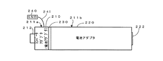
図17は、本発明の給電制御装置における機構的構成の一例を表す外観図である。この給電制御装置は、所定の電池を定格数である複数個保持してこれら電池の直列接続による定格起電力を得るように構成された電池ホルダに保持される一の電池に替えて適用される電池アダプタとして構成され、全体として実電池に相応する形状・寸法を有する。
図14の給電制御装置120が、その内部にコンバータ部と付加機能部とを備えているものであったのに対し、図17のものでは、コンバータ部を含むコンバータアダプタがユニット化され、他の所定の構体との組み合わせによって電池ホルダに保持され得る形状・寸法を成す相対的に小型の外装体を有する点が相違点であり且つ一つの特徴点である。
FIG. 17 is an external view illustrating an example of a mechanical configuration in the power supply control device of the present invention. This power supply control device is applied in place of a single battery held in a battery holder configured to hold a plurality of predetermined batteries of a rated number and obtain a rated electromotive force by connecting these batteries in series. It is configured as a battery adapter and as a whole has a shape and dimensions corresponding to an actual battery.
The power
図17において、図14のものと略同様のコンバータ部を外装体211a内部に備えたコンバータアダプタ210と、図14のものと略同様のものであり得る付加機能部を外装体211b内部に備えた一つの電池アダプタ220である所定の構体とが、両者を着脱自在に結ぶジョイントアダプタ230の部分で接合される形で縦列に並ぶ配置で組み合わせられている。
In FIG. 17, a
コンバータアダプタ210からは、「GND」と表記して概念的に表された接地用導体であって電池ホルダの所定の接触子との電気的接触を得るために設けられた接触導体部240に接続される電源供給用導線241が導出され、また、コンバータアダプタ210の正極側の端部には実電池と同様の正極側接触子212が形成されている。
一方、付加機能部を含む他の構体である電池アダプタ220の負極側の端部には実電池と同様の負極側接触子222が形成されている。
また、ジョイントアダプタ230は、コンバータアダプタ210または更に他の電池アダプタ220と着脱自在に結合して該結合したコンバータアダプタまたは更に他の電池アダプタ220との間もしくは電池ホルダ側の所定の導体との間を結んで所要の電気的接触を得る導体部を備えている。
The
On the other hand, a negative
Further, the
図18は、本発明の給電制御装置の機構的構成の他の例を表す図である。図18(a)は、3つの電池アダプタが縦列に組み合わされて給電制御装置を成す場合の外観図であり、図18(b)は、図18(a)におけるような電池アダプタの縦列接続中に介挿されるジョイントアダプタを表す平面図である。
図19は、図18の給電制御装置における電気的要素の接続関係を表す図である。図18および図19において、既述の図17との対応部には同一の参照符号を付してある。
FIG. 18 is a diagram illustrating another example of the mechanical configuration of the power supply control device of the present invention. FIG. 18A is an external view in the case where three battery adapters are combined in a column to form a power supply control device, and FIG. 18B is a column adapter being connected in a column as shown in FIG. It is a top view showing the joint adapter inserted in.
FIG. 19 is a diagram illustrating a connection relationship of electrical elements in the power supply control device of FIG. In FIG. 18 and FIG. 19, the same reference numerals are assigned to the corresponding parts in FIG.
図18においては、各別の外装体211c、211d、211eを有する3つの電池アダプタが縦列に組み合わされて一つの実電池に相応する形状・寸法を成している。このように組み合わされた形態において、図19を併せ参照して容易に理解されるとおり、実電池の正極側に相当する位置には、図17を参照して説明したものと同様のコンバータアダプタ210が配され、次いで、このコンバータアダプタ210に縦列して接する位置に例えば給電制御部に相応する一の付加機能部272を有する電池アダプタ223がジョイントアダプタ231を介して接続され、更に、この給電制御装置223に続く実電池の負極側に相当する位置には、ジョイントアダプタ232を介して例えばスイッチ部に相応する他の付加機能部273を有する電池アダプタ224が接続されている。
In FIG. 18, three battery adapters having different exterior bodies 211c, 211d, and 211e are combined in a column to form a shape and size corresponding to one real battery. In such a combined form, as easily understood with reference to FIG. 19, the
図18(a)に表されているように、電池アダプタ223、および、224には、図17において参照符号222を付して既述のような、給電制御装置の負極側の端部に設けられた負極側接触子262および263が設けられている。
各ジョイントアダプタ231および232は、図18(b)に代表的に参照符号230を付して示すものであり、中央部に給電制御装置の負極側接触子をその厚み方向の突出部分を包囲する凹部または貫通孔233が形成された絶縁体である環状の構造部材251で構成されている。
As shown in FIG. 18A, the
Each of the
環状の構造部材251にはその周方向に所定間隔で複数の接続導体252,252が構造部材251を厚み方向に貫くように配されている。これらの接続導体252,252は、コンバータアダプタ210のコンバータ部271への一次側(入力側)への電源供給導体(例えば、実電池の起電力である1.2ボルトの電源供給線であり図19では一本の実線にVSと付記)、コンバータ部271から各電池アダプタ223、224への電源供給導体(例えば、コンバータ部からの昇圧出力である3.0ボルトの電源供給線であり図14では一本の実線にVSと付記)、接地導体(図14では一本の実線にGNDと付記)、および、信号伝達用のシリアルバスを構成する複数の導体(図19では白抜きの矢線にSBと付記)として各所要の電気的導通状態を確保するように割当てられている。
A plurality of connecting
尚、このようなシリアルバスを構成する導体を有するものとしてシステムを構築する場合には、付加機能部の一または複数のもの(例えば既述の実施例の場合は給電制御部)をマイクロプロセッサを含んでなるシステムコントローラとして機能するようにし、このシステムコントローラと他の機能部とをシリアルバスで結ぶようにして高度で多様な機能を付加することが可能になる。これは、以下に参照する該当する各図の例において同様である。 In the case of constructing a system having conductors constituting such a serial bus, one or a plurality of additional function units (for example, the power supply control unit in the above-described embodiment) is replaced with a microprocessor. It is possible to add a variety of advanced functions by functioning as a system controller including the system controller and connecting the system controller and other functional units via a serial bus. This is the same in the examples of the corresponding drawings referred to below.
図18(a)に表されたように3つの電池アダプタが縦列に組み合わされて一つの実電池に相応する形状・寸法を成している状態において、電池アダプタ223、224はジョイントアダプタ230(231,232)の上述のような接続導体252,252を通して、コンバータアダプタ210に電源(VS)が供給され、また、コンバータアダプタ210で昇圧された電源(VD)が各電池アダプタ223、224の付加機能部272、273に供給される。
また、各電池アダプタ223、224の付加機能部272、273間は、ジョイントアダプタ230(231,232)のシリアルバスを成す導体を通して信号の授受が行われる。
As shown in FIG. 18A, in a state where three battery adapters are combined in a column to form a shape and size corresponding to one real battery, the
In addition, signals are transmitted and received between the
図20は、本発明の給電制御装置の機構的構成の更に他の例を表す図である。
図21は、図20の給電制御装置における電気的要素の接続関係を表す図である。
図20および図21において、既述の図18および図19との対応部には同一の参照符号を付してある。
図20においても、3つの電池アダプタが縦列に組み合わされて一つの実電池に相応する形状・寸法を成しているが、図20の実施例では、このように組み合わされた形態を維持するために、電池アダプタと他の構体(図示の場合はこれも電池アダプタである)とを一体に組付けるための構造部材251を有する組付けフレーム250を適用している。
FIG. 20 is a diagram illustrating still another example of the mechanical configuration of the power supply control device of the present invention.
FIG. 21 is a diagram illustrating a connection relationship of electrical elements in the power supply control device of FIG.
20 and FIG. 21, the same reference numerals are assigned to the corresponding parts in FIG. 18 and FIG.
Also in FIG. 20, three battery adapters are combined in tandem to form a shape and size corresponding to one actual battery, but in the embodiment of FIG. 20, in order to maintain such a combined form. In addition, an
図21を併せ参照して容易に理解されるとおり、実電池の正極側に相当する位置には、図17を参照して説明したものと同様のコンバータアダプタ210が配され、次いで、このコンバータアダプタ210に縦列して接する位置に例えば給電制御部に相応する一の付加機能部272を有する電池アダプタ223がジョイントアダプタ231を介して接続され、更に、この電池アダプタ223に続く実電池の負極側に相当する位置には、ジョイントアダプタ232を介して例えばスイッチ部に相応する他の付加機能部273を有する電池アダプタ224が接続されている。
As easily understood with reference to FIG. 21, a
図20における組付けフレーム250は、これの内部ないし適所に設けられた導体253によって、コンバータアダプタ210(そのコンバータ部271)への電源供給のための導電路が構成されており、図21では、この部分の機能を表記するべくコンバータアダプタ210のブロックから下方に突出する如く描かれている。
図21における各給電制御装置、即ち、コンバータアダプタ210および、その他の2つの電池アダプタ223および224、ならびに、2つのジョイントアダプタ231および232については、図19を参照して説明したものと同様である。
In the
Each power supply control device in FIG. 21, that is, the
図20のような組付けフレーム250を適用することによって、単体では実電池の寸法に満たない相対的に小型の外装体を有する電池アダプタ(210、223、および、224)に対して、この給電制御装置と他の構体(この構体は図示の例におけるように他の給電制御装置であり得る)とを一体に組付けることによって、電池ホルダに適合する形状・寸法を成すことができる。
また、給電制御装置と他の構体とを着脱自在に組付け得るように構成されているため、コンバータアダプタの他に種々の電池アダプタを任意に選択的に適用して多様な機能を実現することが可能になる。
20 is applied to the battery adapters (210, 223, and 224) having a relatively small exterior body that is smaller than the actual battery size by itself. By integrally assembling the control device and another structure (this structure may be another power supply control device as in the illustrated example), it is possible to form a shape and size suitable for the battery holder.
In addition, since the power supply control device and the other structure can be detachably assembled, various battery adapters can be selectively applied in addition to the converter adapter to realize various functions. Is possible.
図22は、本発明の給電制御装置の機構的構成の更に他の例を表す図である。
図23は、図22の給電制御装置における電気的要素の接続関係を表す図である。
図22および図23において、既述の図18および図19との対応部には同一の参照符号を付してある。
図22においても、3つの電池アダプタが縦列に組み合わされて一つの実電池に相応する形状・寸法を成しているが、図22の実施例では、3つの電池アダプタのうち最も正極側にはスイッチ機能部を内蔵したコンバータアダプタ210aが配され、これに続いて配された2つの電池アダプタ223a、224aは何れも給電制御信号を生成する給電制御部272a、273aを含むものである。
FIG. 22 is a diagram illustrating still another example of the mechanical configuration of the power supply control device of the present invention.
FIG. 23 is a diagram illustrating a connection relationship of electrical elements in the power supply control device of FIG.
22 and FIG. 23, the same reference numerals are assigned to the corresponding parts in FIG. 18 and FIG. 19 described above.
Also in FIG. 22, three battery adapters are combined in a column to form a shape and size corresponding to one actual battery, but in the embodiment of FIG. A
また、コンバータアダプタ210aは外装体211fを有し、電池アダプタ223a、224aは外装体211g,211hを各有する。
図23を併せ参照して容易に理解されるとおり、実電池の正極側に相当する位置には、上述のようなスイッチ機能内蔵型のコンバータアダプタ210aが配され、次いで、このコンバータアダプタ210aに縦列して接する位置に、付加機能部272aとして温度を検出するセンサモジュールが一体的に組み合わされた温度センサ内蔵型給電制御部を含む電池アダプタ223aがジョイントアダプタ231を介して接続され、更に、この電池アダプタ223aに続く実電池の負極側に相当する位置には、ジョイントアダプタ232を介して、他の付加機能部273aとして限時動作を行うタイマ機能内蔵型給電制御部を含む電池アダプタ224aが接続されている。
The
As easily understood with reference to FIG. 23, the
図22および図23の各個の電池アダプタの組み合わせによる作用について更に説明する。
電池アダプタ210aは、コンバータ部を含む点は既述の実施例と同様であるが、本例のものでは更にコンバータ部の出力を所定の負荷に供給する給電経路1に介挿され給電制御信号に応じて給電経路を開閉するスイッチ部(スイッチ機能部)が一体的に構成されたスイッチ機能部内蔵型のコンバータ部を含んでいる。
The effect | action by the combination of each battery adapter of FIG. 22 and FIG. 23 is further demonstrated.
The
コンバータアダプタとしての電池アダプタ210aにおける上記のスイッチ部(スイッチ機能部)に対して、電池アダプタ223aまたは電池アダプタ224aから給電制御信号が供給されてその開閉が制御される。
例えば、電池アダプタ223aからその温度センサ内蔵型給電制御部によって環境温度の異常上昇時に負荷への給電を断つようなフェールセーフ動作を行うための給電制御信号が供給され、或いはまた、電池アダプタ224aからそのタイマ機能内蔵型給電制御部によって負荷への給電に関する時間的制限を行うといった給電制御が行われ得る。
更に、電池アダプタ224aのタイマ機能によって直接負荷への給電を制御するのではなく、所定の時間帯に限って電池アダプタ223aの温度センサを作動させ乃至は温度センサによる検出出力を有効にして給電制御を行うといった制御が可能になる。
The power supply control signal is supplied from the
For example, the
Further, the power supply control is not performed by directly controlling the power supply to the load by the timer function of the
図24は、本発明の給電制御装置の機構的構成の更に他の例を表す図である。
図25は、図24の給電制御装置における電気的要素の接続関係を表す図である。
図24および図25において、既述の図20ないし図23との対応部には同一の参照符号を付してある。
図24を図20と対比して容易に理解されるとおり、図24の例においても図20におけると同様の組付けフレーム250を利用して3つの電池アダプタが縦列に組み合わせ、これによって一つの実電池に相応する形状・寸法を成すようにしている。
FIG. 24 is a diagram illustrating still another example of the mechanical configuration of the power supply control device of the present invention.
FIG. 25 is a diagram illustrating a connection relationship of electrical elements in the power supply control device of FIG.
24 and 25, the same reference numerals are assigned to the corresponding parts in FIGS. 20 to 23 described above.
As can be easily understood by comparing FIG. 24 with FIG. 20, also in the example of FIG. 24, three battery adapters are combined in a column using the
また、各個の電池アダプタ210a,223a、224aについては、コンバータアダプタとしての電池アダプタ210aが外装体211fを有し、電池アダプタ223a、224aは外装体211g,211hを各有する点を含んで図22ないし図23を参照して既述のものと同様である。
即ち、実電池の正極側に相当する位置には、スイッチ機能内蔵型のコンバータアダプタ210aが配され、次いで、このコンバータアダプタ210aに縦列して接する位置に、ジョイントアダプタ231を介して、付加機能部272aとして温度を検出するセンサモジュールが一体的に組み合わされた温度センサ内蔵型給電制御部を含む電池アダプタ223aが接続され、更に、この電池アダプタ223aに続く実電池の負極側に相当する位置には、ジョイントアダプタ232を介して、他の付加機能部273aとして限時動作を行うタイマ機能内蔵型給電制御部を含む電池アダプタ224aが接続されている。
Further, for each
That is, a
図24および図25を参照して説明した電池アダプタの組み合わせによる作用についても、図22および図23参照して説明したところと同様である。
即ち、コンバータアダプタとしての電池アダプタ210aにおけるスイッチ機能部に対して、電池アダプタ223aまたは電池アダプタ224aから給電制御信号が供給されてその開閉が制御される。
The operation of the combination of battery adapters described with reference to FIGS. 24 and 25 is the same as that described with reference to FIGS. 22 and 23.
That is, the power supply control signal is supplied from the
例えば、電池アダプタ223aからその温度センサ内蔵型給電制御部によって環境温度の異常上昇時に負荷への給電を断つようなフェールセーフ動作を行うための給電制御信号が供給され、或いはまた、電池アダプタ224aからそのタイマ機能内蔵型給電制御部によって負荷への給電に関する時間的制限を行うといった給電制御が行われ得る。
更に、電池アダプタ224aのタイマ機能によって直接負荷への給電を制御するのではなく、所定の時間帯に限って電池アダプタ223aの温度センサを作動させ乃至は温度センサによる検出出力を有効にして給電制御を行うといった制御が可能になる。
For example, the
Further, the power supply control is not performed by directly controlling the power supply to the load by the timer function of the
11…第1の接触子 12…第2の接触子 12a…第4の接触子 12b…第6の接触子 13…第3の接触子 13a…第5の接触子 13b…第7の接触子 14…第8の接触子 110…ニッケル水素充電電池 120,1200,1200a,1200b,5200,5200a,6200,6200a…給電制御装置 121,1210…外装体 122…コンバータ部 122…コンバータ部 123…電源供給用導線 125…実装スペース 126…付加機能部 210,210a…コンバータアダプタ 211,211a,211b,211c,211d,211e,211f,211g,211h…外装体 212…正極側接触子 220,223,223a,224,224a…電池アダプタ 222,262,263…負極側接触子 230,231,232…ジョイントアダプタ 233…凹部(貫通孔) 240…接触導体部 241…電源供給用導線 251…構造部材 252…接続導体 271,272,272a,273,273a…付加機能部 1000…音声記録再生装置 1001…音声記録用マイクロフォン 1002…音声出力用スピーカ 1003…デッキ部 1004…アンテナ 1005…選局用ダイヤル 1006…チューニングインジケータ 1100,5100,6100…電池ホルダ 1220,5220,6220…コンバータ部 1500…負荷(受信回路) 1221,5221,6221…給電経路 1230,5230,6230…スイッチ部 1240,1240a,1240b,5240,6240…給電制御部 1241…タイマ回路 1242,5242a…短距離高速無線ネットワーク・インターフェース 1243,6350…モーションセンサ 5000…懐中電灯 5001…本体 5002…把持部 5003,6004…手動電源スイッチ 5004…光出射面 5235,6235…負荷(光源) 5242…アンテナ回路 5500…携帯情報端末装置 5501…ファンクションキー 5502…文字入力キー 5503…ディスプレイ 5600,6600…携帯情報端末装置 5601,6601…カメラ 6000…LED式ランタン 6001…本体 6002…把持部 6003…カバー 6005…光源 6242,6242a…センサ・インターフェース 6300…測温抵抗体 6400…水槽 5241,5241a,6241,6241a…被送信情報受信部 5242…アンテナ回路
DESCRIPTION OF
Claims (10)
前記電池ホルダに当該複数個のうちの一の電池に替えて自己が保持されるに適合する形状・寸法を成し得る外装体と、
前記外装体内に配され、前記外装体が当該一の電池に替えて前記電池ホルダに保持されたときには当該他の電池の起電力の合算値に相応する電圧の供給を受けて該供給された電圧を前記定格起電力に相応する出力電圧に変換するコンバータ部と、
前記コンバータ部の出力を所定の負荷に供給する給電経路に介挿され給電制御信号に応じて前記給電経路を開閉するスイッチ部と、
前記スイッチ部に供給する前記給電制御信号を生成する給電制御部と、を備え、
前記給電制御部が、前記電池駆動式機器の外部から供給される被送信情報を受信する被送信情報受信部を有し、該被送信情報受信部で受信された被送信情報に基づいて前記給電制御信号を生成するように構成されていることを特徴とする給電制御装置。 A battery-driven type configured to supply a predetermined load from a battery holder configured to hold a plurality of batteries having a predetermined specification and obtain a rated electromotive force by connecting the rated number of batteries in series. A power supply control device applied to a device,
An exterior body capable of forming a shape and size suitable for holding the battery holder in place of one of the plurality of batteries in the battery holder;
When the outer body is disposed in the outer body and the outer body is held in the battery holder instead of the one battery, the supplied voltage is supplied with a voltage corresponding to the sum of the electromotive forces of the other batteries. Converter unit for converting the output voltage into an output voltage corresponding to the rated electromotive force,
A switch unit that is inserted into a power supply path that supplies the output of the converter unit to a predetermined load and opens and closes the power supply path according to a power supply control signal;
A power supply control unit that generates the power supply control signal to be supplied to the switch unit, and
The power supply control unit includes a transmitted information receiving unit that receives transmitted information supplied from outside the battery-powered device, and the power supply is performed based on the transmitted information received by the transmitted information receiving unit. A power supply control device configured to generate a control signal.
前記スイッチ部は、前記負荷としての前記照明装置の光源への電源供給経路に介挿されるようにして設けられ、
前記給電制御部は、前記被送信情報受信部で受信された被送信情報に応じて前記光源による照明光に変調を与えるように前記給電制御信号を生成するように構成されていることを特徴とする請求項1に記載の給電制御装置。 The exterior body is configured to be applied to a battery holder of a lighting device as the battery-driven device,
The switch unit is provided so as to be inserted in a power supply path to the light source of the lighting device as the load,
The power supply control unit is configured to generate the power supply control signal so as to modulate illumination light from the light source according to the transmitted information received by the transmitted information receiving unit. The power supply control device according to claim 1.
Priority Applications (2)
| Application Number | Priority Date | Filing Date | Title |
|---|---|---|---|
| JP2008037351A JP2008278738A (en) | 2007-04-05 | 2008-02-19 | Power feed controller |
| US12/098,055 US7755335B2 (en) | 2007-04-05 | 2008-04-04 | Feed controller |
Applications Claiming Priority (2)
| Application Number | Priority Date | Filing Date | Title |
|---|---|---|---|
| JP2007099499 | 2007-04-05 | ||
| JP2008037351A JP2008278738A (en) | 2007-04-05 | 2008-02-19 | Power feed controller |
Publications (2)
| Publication Number | Publication Date |
|---|---|
| JP2008278738A true JP2008278738A (en) | 2008-11-13 |
| JP2008278738A5 JP2008278738A5 (en) | 2011-02-17 |
Family
ID=40056039
Family Applications (2)
| Application Number | Title | Priority Date | Filing Date |
|---|---|---|---|
| JP2008037351A Withdrawn JP2008278738A (en) | 2007-04-05 | 2008-02-19 | Power feed controller |
| JP2008037350A Withdrawn JP2008278737A (en) | 2007-04-05 | 2008-02-19 | Power feed controller |
Family Applications After (1)
| Application Number | Title | Priority Date | Filing Date |
|---|---|---|---|
| JP2008037350A Withdrawn JP2008278737A (en) | 2007-04-05 | 2008-02-19 | Power feed controller |
Country Status (1)
| Country | Link |
|---|---|
| JP (2) | JP2008278738A (en) |
Cited By (1)
| Publication number | Priority date | Publication date | Assignee | Title |
|---|---|---|---|---|
| JP2013150463A (en) * | 2012-01-19 | 2013-08-01 | Hitachi Koki Co Ltd | Non-contact charger, power tool with non-contact charging function, non-contact charging system, and non-contact charging method |
Families Citing this family (1)
| Publication number | Priority date | Publication date | Assignee | Title |
|---|---|---|---|---|
| JP6950608B2 (en) * | 2018-03-29 | 2021-10-13 | セイコーエプソン株式会社 | Control device, power receiving device and electronic device |
-
2008
- 2008-02-19 JP JP2008037351A patent/JP2008278738A/en not_active Withdrawn
- 2008-02-19 JP JP2008037350A patent/JP2008278737A/en not_active Withdrawn
Cited By (1)
| Publication number | Priority date | Publication date | Assignee | Title |
|---|---|---|---|---|
| JP2013150463A (en) * | 2012-01-19 | 2013-08-01 | Hitachi Koki Co Ltd | Non-contact charger, power tool with non-contact charging function, non-contact charging system, and non-contact charging method |
Also Published As
| Publication number | Publication date |
|---|---|
| JP2008278737A (en) | 2008-11-13 |
Similar Documents
| Publication | Publication Date | Title |
|---|---|---|
| US10104463B2 (en) | Wireless sound equipment | |
| ES2325734T3 (en) | CHARGER AND RECHARGEING DEVICE. | |
| CN100454638C (en) | Fuel cell, fuel cartridge, and fuel cell system | |
| US8339304B2 (en) | Remote control signal generation device and remote control system | |
| US8311592B2 (en) | Portable terminal having external module and method for displaying charged status thereof | |
| CN208904670U (en) | It is a kind of can the intelligent vehicle of interactive voice fill | |
| KR20050066696A (en) | Charging adapter for wireless earphone | |
| KR20150122362A (en) | Mobile terminal | |
| WO2011001547A1 (en) | Case for portable terminal | |
| CN105910023A (en) | Lighting apparatus, lighting system, and control method | |
| CN108551504A (en) | A kind of multi-functional comprehensive screen mobile phone | |
| CN105788489A (en) | Tour guide walking stick and tour guide system with same | |
| JP2014155030A (en) | Light emitting module for specific radio signal | |
| JP2008278738A (en) | Power feed controller | |
| JP2008283669A (en) | Remote control signal generation device, and remote control system | |
| CN107519651A (en) | Block structural unit and Block structural unit control system | |
| US7755335B2 (en) | Feed controller | |
| US20070172091A1 (en) | Ear hook for a wireless headset and a carrying device thereof | |
| CN205428493U (en) | On -vehicle cigar lighter formula bluetooth MP3 player device of intelligence | |
| CN212782667U (en) | Intelligent tour guide hat | |
| CN211128124U (en) | Neck strap type earphone | |
| KR102149528B1 (en) | Multi-function wireless charging device | |
| KR200353723Y1 (en) | Portable rapidity a charger of multi function | |
| CN205792879U (en) | There is the miniature image input equipment of dual combination structure | |
| CN206514215U (en) | A kind of lighting apparatus for supporting to extend |
Legal Events
| Date | Code | Title | Description |
|---|---|---|---|
| A521 | Written amendment |
Free format text: JAPANESE INTERMEDIATE CODE: A523 Effective date: 20101228 |
|
| A621 | Written request for application examination |
Free format text: JAPANESE INTERMEDIATE CODE: A621 Effective date: 20101228 |
|
| RD04 | Notification of resignation of power of attorney |
Free format text: JAPANESE INTERMEDIATE CODE: A7424 Effective date: 20110630 |
|
| A761 | Written withdrawal of application |
Free format text: JAPANESE INTERMEDIATE CODE: A761 Effective date: 20120305 |