JP2008268385A - Image forming apparatus - Google Patents
Image forming apparatus Download PDFInfo
- Publication number
- JP2008268385A JP2008268385A JP2007108755A JP2007108755A JP2008268385A JP 2008268385 A JP2008268385 A JP 2008268385A JP 2007108755 A JP2007108755 A JP 2007108755A JP 2007108755 A JP2007108755 A JP 2007108755A JP 2008268385 A JP2008268385 A JP 2008268385A
- Authority
- JP
- Japan
- Prior art keywords
- transfer
- moisture content
- forming apparatus
- image forming
- resistance value
- Prior art date
- Legal status (The legal status is an assumption and is not a legal conclusion. Google has not performed a legal analysis and makes no representation as to the accuracy of the status listed.)
- Pending
Links
Images


Abstract
Description
本発明は、画像形成装置に関し、詳細には、像担持体上のトナー画像を転写して画像を形成する画像形成装置に関する。 The present invention relates to an image forming apparatus, and more particularly to an image forming apparatus that transfers a toner image on an image carrier to form an image.
複写機、ファクシミリ装置及びプリンタ等に画像形成装置においては、近時、電子写真方式の画像形成装置が普及してきている。 Recently, electrophotographic image forming apparatuses have become widespread in image forming apparatuses such as copying machines, facsimile machines, and printers.
このような電子写真方式で画像形成を行う場合、一様に帯電させた感光体上に画像データにより変調したレーザビームを照射して静電潜像を形成して、該静電潜像を現像ユニットでトナーを用いて現像し、該トナー画像を給紙部から搬送されてくる転写紙に転写して、トナー画像を転写紙に形成したり、感光体上のトナー画像を中間転写ベルトに転写して、該中間転写ベルト上のトナー画像を転写紙に転写している。画像形成装置は、このトナー画像を転写した転写紙を定着部で、加熱・加圧しつつ搬送して、トナー画像を転写紙に定着させる。 When performing image formation by such an electrophotographic method, an electrostatic latent image is formed by irradiating a uniformly charged photosensitive member with a laser beam modulated by image data, and developing the electrostatic latent image. The toner is developed in the unit, and the toner image is transferred to the transfer paper conveyed from the paper feed unit to form the toner image on the transfer paper, or the toner image on the photoconductor is transferred to the intermediate transfer belt. Thus, the toner image on the intermediate transfer belt is transferred to the transfer paper. The image forming apparatus conveys the transfer paper onto which the toner image is transferred while being heated and pressurized by the fixing unit, and fixes the toner image on the transfer paper.
そして、従来の電子写真方式の画像形成装置は、感光体上または中間転写ベルト上のトナー画像の転写紙への転写においては、転写する転写紙の紙種、紙サイズ等によって転写電圧を適宜変更することによって、転写性能を一定にして、安定した濃度の画像形成を行っている。 In the conventional electrophotographic image forming apparatus, when transferring the toner image on the photoreceptor or the intermediate transfer belt to the transfer paper, the transfer voltage is appropriately changed depending on the paper type, paper size, etc. of the transfer paper to be transferred. By doing so, image formation with a stable density is performed with the transfer performance kept constant.
また、従来から転写紙へのトナー画像の転写性能は、温度や湿度等の環境条件等によって転写構成部品(転写ローラや転写ベルト等)や紙の抵抗が高くなると、電流を一定にして転写性能を一定にするために、転写電圧として、高電圧が必要となる。 Conventionally, the transfer performance of toner images onto transfer paper is such that when the transfer component (transfer roller, transfer belt, etc.) or paper resistance increases due to environmental conditions such as temperature and humidity, the current is kept constant. Therefore, a high voltage is necessary as a transfer voltage.
ところが、高電圧を印加すると、転写部で放電が起き易くなり、不良画像を発生させたり、また、高圧電源を用いることで、コストが高くなる。この場合、高電圧が印加されて転写部での放電を防止するために、電圧の上限リミッタを設けることも従来行われているが、本来転写電流を一定にするために必要な転写電圧を印加することができず、転写電流の不足によって、最適な転写性が得られず、画像不良が発生するという問題があった。 However, when a high voltage is applied, discharge easily occurs at the transfer portion, and a defective image is generated, and the use of a high voltage power source increases the cost. In this case, in order to prevent a discharge at the transfer portion when a high voltage is applied, a voltage upper limiter is also provided in the past, but a transfer voltage that is originally necessary to make the transfer current constant is applied. However, due to the lack of transfer current, optimal transferability cannot be obtained, and image defects occur.
そして、従来、外部環境条件である画像形成装置の筐体内の温湿度や転写紙の抵抗値を転写条件として検出して、該転写条件に基づいて転写電圧・電流印加部に転写紙を挟んで対向する転写対向部と接地間に設けられた可変抵抗器の抵抗値を変化させる画像形成装置が提案されている(特許文献1参照)。 Conventionally, the temperature and humidity in the housing of the image forming apparatus and the resistance value of the transfer paper, which are external environmental conditions, are detected as transfer conditions, and the transfer paper is sandwiched between transfer voltage / current application units based on the transfer conditions. There has been proposed an image forming apparatus that changes the resistance value of a variable resistor provided between an opposing transfer facing portion and ground (see Patent Document 1).
この従来技術は、転写部における総抵抗値を一定にして、転写電流を確保するための転写電圧も一定にすることで、電圧変動による高圧印加を防止して、転写不良(チリやボソツキなど)の発生を防止しようとしている。 This conventional technology keeps the total resistance value in the transfer section constant and also makes the transfer voltage constant to secure the transfer current, thereby preventing the application of high voltage due to voltage fluctuations and transferring defects (such as dust and vomit) Is trying to prevent the occurrence of.
しかしながら、上記従来技術にあっては、筐体内の温度・湿度を測定して、転写部における総抵抗を決定しているので、より一層安定した転写性能を確保して画像品質を向上させる上で、改良の必要があった。 However, in the above prior art, since the total resistance in the transfer portion is determined by measuring the temperature and humidity in the housing, in order to ensure a more stable transfer performance and improve the image quality. There was a need for improvement.
すなわち、転写性能に影響するのは、外部環境としての温湿度だけでなく、転写材や転写部の構成部品(転写ローラ、転写対向ローラ、中間転写ベルト等)の湿度状態が大きく影響する。例えば、画像形成装置内部の温湿度環境とは異なる環境に置かれていた転写材を画像形成装置内に収納した直後に印刷した場合には、転写材の湿度と筐体内の湿度とが異なり、筐体内の温湿度に基づいて転写部の総抵抗を決定して転写電圧・電流を決定すると、適切な転写電圧・電流を供給することができず、画質が悪化するという問題があった。 That is, not only the temperature and humidity as the external environment but also the humidity state of the transfer material and the components of the transfer unit (transfer roller, transfer counter roller, intermediate transfer belt, etc.) greatly affect the transfer performance. For example, when printing is performed immediately after the transfer material that has been placed in an environment different from the temperature and humidity environment inside the image forming apparatus is stored in the image forming apparatus, the humidity of the transfer material is different from the humidity in the housing. If the total resistance of the transfer portion is determined based on the temperature and humidity in the housing and the transfer voltage / current is determined, an appropriate transfer voltage / current cannot be supplied, and the image quality deteriorates.
そこで、本発明は、適切な転写電圧・電流を供給して、画像品質の良好な画像形成装置を提供することを目的としている。 SUMMARY An advantage of some aspects of the invention is that it provides an image forming apparatus with good image quality by supplying appropriate transfer voltage and current.
請求項1記載の発明の画像形成装置は、現像剤像の形成されている像担持体と転写材を、転写電圧印加手段と可変抵抗手段を介して接地されている対向手段との間に位置させて、該像担持体と該転写材を挟んで該転写電圧印加手段から該対向手段に所定の転写電圧・電流を印加して該像担持体上の現像剤像を該転写材に転写させる画像形成装置において、前記像担持体、前記転写電圧印加手段、前記対向手段及び前記転写材を主要な構成手段とする転写部の総抵抗値を検出する転写部抵抗値検出手段と、該転写部抵抗値検出手段の検出した該転写部の総抵抗値に基づいて前記可変抵抗手段の抵抗値を調整する抵抗値調整手段とを備えていることにより、上記目的を達成している。 The image forming apparatus according to the first aspect of the invention is configured such that an image carrier on which a developer image is formed and a transfer material are positioned between a transfer voltage applying unit and a counter unit grounded via a variable resistance unit. Then, a predetermined transfer voltage / current is applied from the transfer voltage applying means to the opposing means with the image carrier and the transfer material interposed therebetween, and the developer image on the image carrier is transferred to the transfer material. In the image forming apparatus, a transfer unit resistance value detecting unit that detects a total resistance value of a transfer unit including the image carrier, the transfer voltage applying unit, the facing unit, and the transfer material as main constituent units, and the transfer unit The above object is achieved by including resistance value adjusting means for adjusting the resistance value of the variable resistance means based on the total resistance value of the transfer portion detected by the resistance value detecting means.
この場合、例えば、請求項2に記載するように、前記画像形成装置は、感光体上に形成された現像剤像を前記像担持体としての中間転写体上に転写して、該中間転写体上の現像剤像を前記転写部で前記転写材に転写する画像形成装置であってもよい。 In this case, for example, as described in claim 2, the image forming apparatus transfers the developer image formed on the photosensitive member onto the intermediate transfer member as the image carrier, and the intermediate transfer member. The image forming apparatus may transfer the upper developer image to the transfer material at the transfer unit.
また、例えば、請求項3に記載するように、前記画像形成装置は、感光体上に形成された複数色の現像剤像を前記像担持体としての中間転写体上に順次重ね合わせて転写してカラー現像剤像を形成し、該中間転写体上のカラー現像剤像を前記転写部で前記転写材に転写するカラー画像形成装置であってもよい。 Further, for example, as described in claim 3, the image forming apparatus sequentially transfers a plurality of color developer images formed on a photoreceptor on an intermediate transfer member as the image carrier. A color image forming apparatus that forms a color developer image and transfers the color developer image on the intermediate transfer member to the transfer material by the transfer unit may be used.
さらに、例えば、請求項4に記載するように、前記転写部抵抗値検出手段は、前記転写部を構成する転写部構成手段のうち1つ以上の転写部構成手段の含水率を検出する含水率検出手段と、該含水率検出手段の検出する含水率に基づいて前記総抵抗値を算出する抵抗値算出手段とを備えていてもよい。 Further, for example, as described in claim 4, the transfer portion resistance value detecting means detects a moisture content of one or more transfer portion constituting means among the transfer portion constituting means constituting the transfer portion. You may provide a detection means and the resistance value calculation means which calculates the said total resistance value based on the moisture content which this moisture content detection means detects.
また、例えば、請求項5に記載するように、前記含水率検出手段は、検出対象の前記転写部構成手段の含水率に応じてその反射量の変化する近赤外線を用いた光検出手段であってもよい。 Further, for example, as described in claim 5, the moisture content detection means is a light detection means using near infrared rays whose reflection amount changes according to the moisture content of the transfer unit constituting means to be detected. May be.
さらに、例えば、請求項6に記載するように、前記含水率検出手段は、検出対象の前記転写部構成手段に接触して該転写部構成手段の含水率を直接検出する接触型含水率検出手段であってもよい。 Further, for example, as described in claim 6, the moisture content detecting means is a contact-type moisture content detecting means for directly detecting the moisture content of the transfer portion constituting means by contacting the transfer portion constituting means to be detected. It may be.
また、例えば、請求項7に記載するように、前記含水率検出手段は、検出対象の前記転写部構成手段の移動方向に対して直交する方向に複数並んで配設されていてもよい。
Further, for example, as described in
さらに、例えば、請求項8に記載するように、前記抵抗値算出手段は、複数の前記含水率検出手段の検出結果から平均含水率を算出し、該平均含水率に基づいて前記総抵抗値を算出してもよい。 Furthermore, for example, as described in claim 8, the resistance value calculating unit calculates an average moisture content from detection results of the plurality of moisture content detecting units, and calculates the total resistance value based on the average moisture content. It may be calculated.
また、例えば、請求項9に記載するように、前記含水率検出手段は、所定時間内に前記含水率の検出を複数回を行い、前記抵抗値算出手段は、該複数回の含水率検出結果から平均含水率を算出し、該平均含水率に基づいて前記総抵抗値を算出してもよい。 Further, for example, as described in claim 9, the moisture content detection means performs the moisture content detection a plurality of times within a predetermined time, and the resistance value calculation means obtains the moisture content detection results of the plurality of times. The average moisture content may be calculated from the average moisture content, and the total resistance value may be calculated based on the average moisture content.
さらに、例えば、請求項10に記載するように、前記画像形成装置は、複数の前記含水率検出手段の検出した含水率検出結果または/及び前記含水率検出手段の複数回の含水率検出結果を記憶する記憶手段を備え、前記抵抗値算出手段は、該記憶手段の含水率検出結果から前記平均含水率を算出してもよい。
Further, for example, as described in
また、例えば、請求項11に記載するように、前記含水率検出手段は、前記転写材への前記現像剤像の転写位置近傍であって、前記転写部構成手段の該転写位置への移動方向手前位置に配設されていてもよい。
Further, for example, as described in
さらに、例えば、請求項12に記載するように、前記画像形成装置は、それぞれ異なる前記転写部構成手段の含水率を検出する複数の前記含水率検出手段を備え、前記転写部材が前記転写電圧印加手段近傍の所定位置に搬送されてきた時点で、該複数の含水率検出手段で対応する該転写部構成手段の含水率を同時に検出してもよい。
Furthermore, for example, as described in
本発明の画像形成装置によれば、像担持体上の現像剤像を転写材に転写する転写部の総抵抗値を検出して、該検出した転写部の総抵抗値に基づいて、該転写部の接地間に接続されている可変抵抗手段の抵抗値を調整しているので、転写部の総抵抗値を適切に検出して適切な転写電圧・電流を供給することができ、転写性能を向上させて、画像品質を向上させることができる。 According to the image forming apparatus of the present invention, the total resistance value of the transfer portion that transfers the developer image on the image carrier to the transfer material is detected, and the transfer is performed based on the detected total resistance value of the transfer portion. Since the resistance value of the variable resistance means connected between the ground of each part is adjusted, the total resistance value of the transfer part can be properly detected to supply the appropriate transfer voltage and current, and the transfer performance can be improved. The image quality can be improved.
以下、本発明の好適な実施例を添付図面に基づいて詳細に説明する。なお、以下に述べる実施例は、本発明の好適な実施例であるから、技術的に好ましい種々の限定が付されているが、本発明の範囲は、以下の説明において特に本発明を限定する旨の記載がない限り、これらの態様に限られるものではない。 Hereinafter, preferred embodiments of the present invention will be described in detail with reference to the accompanying drawings. In addition, since the Example described below is a suitable Example of this invention, various technically preferable restrictions are attached | subjected, However, The scope of the present invention limits this invention especially in the following description. As long as there is no description of the effect, it is not restricted to these aspects.
図1〜図5は、本発明の画像形成装置の一実施例を示す図であり、図1は、本発明の画像形成装置の一実施例を適用した画像形成装置1の要部正面概略構成図である。 1 to 5 are diagrams showing an embodiment of an image forming apparatus according to the present invention. FIG. 1 is a schematic front view of a main part of the image forming apparatus 1 to which an embodiment of the image forming apparatus according to the present invention is applied. FIG.
図1において、画像形成装置1は、所定幅を有するリング状の感光体ベルト2が1次転写対向ローラ3、感光体ベルト駆動ローラ4及び搬送ローラ5に張り渡されており、感光体ベルト駆動ローラ4によって図1に矢印で示す時計方向に感光体ベルト2を回転駆動する。また、画像形成装置1は、所定幅を有するリング状の中間転写体(像担持体)6が、1次転写印加ローラ7、中間転写駆動ローラ8、中間転写体テンションローラ9、2次転写対向ローラ10及びベルトクリーニング対向ローラ11に張り渡されており、中間転写駆動ローラ8によって図1に矢印で示す反時計方向に中間転写体6を回転駆動する。
In FIG. 1, an image forming apparatus 1 includes a ring-shaped photosensitive belt 2 having a predetermined width that is stretched over a primary transfer counter roller 3, a photosensitive belt driving roller 4, and a conveying roller 5. The photosensitive belt 2 is rotationally driven by the roller 4 in the clockwise direction indicated by the arrow in FIG. In the image forming apparatus 1, a ring-shaped intermediate transfer body (image carrier) 6 having a predetermined width includes a primary
画像形成装置1は、感光体ベルト2を、時計方向に回転させながら、図示しない帯電部によって一様に帯電させた後、図示しない光書込部によって画像データに基づいて変調した書込光を照射して静電潜像を形成し、該静電潜像を形成した感光体ベルト2に図示しない現像部からトナーを供給して現像することで感光体ベルト2上にトナー画像を形成する。 The image forming apparatus 1 uniformly charges a photosensitive belt 2 with a charging unit (not shown) while rotating the photosensitive belt 2 in a clockwise direction, and then writes writing light modulated based on image data by an optical writing unit (not shown). Irradiation forms an electrostatic latent image, and a toner image is formed on the photosensitive belt 2 by supplying toner from a developing unit (not shown) to the photosensitive belt 2 on which the electrostatic latent image has been formed.
上記1次転写対向ローラ3と1次転写印加ローラ7とは、上記感光体ベルト2と上記中間転写体6を挟んで近接して配設されており、1次転写印加ローラ7には、1次転写バイアス部12が接続されている。
The primary transfer counter roller 3 and the primary
画像形成装置1は、上記感光体ベルト2と中間転写体6を回転移動させながら、1次転写バイアス部12から所定の1次転写バイアス電圧を1次転写印加ローラ7に印加して、該感光体ベルト2上のトナー画像を中間転写体6に転写させる。
The image forming apparatus 1 applies a predetermined primary transfer bias voltage from the primary
画像形成装置1は、中間転写体6を挟んで2次転写対向ローラ10に対向する位置に、2次転写ローラ13が近接して配設されており、2次転写ローラ13には、2次転写電源14が接続されている。
In the image forming apparatus 1, a
中間転写体6は、中間転写体テンションローラ9によって所定のテンションが付与されている状態で、2次転写対向ローラ10と2次転写ローラ13との間に搬送され、この中間転写体6と2次転写ローラ13との間を通過する状態で、図示しない給紙部から転写紙等の転写材15が搬送される。
The intermediate transfer member 6 is conveyed between the secondary
2次転写対向ローラ10と接地との間には、可変抵抗器(可変抵抗手段)16が接続されており、可変抵抗器16は、制御部17によってその抵抗値が調整される。上記ベルトクリーニング対向ローラ11部分には、中間転写体6を挟んで図示しないクリーニングブラシが配設されており、クリーニングブラシは、中間転写体6上に残留するトナー画像をクリーニングする。
A variable resistor (variable resistor means) 16 is connected between the secondary
画像形成装置1は、中間転写体6を回転駆動させながら、該中間転写体6と2次転写ローラ13との間に給紙部から転写材15を搬送して、可変抵抗器16を介して接地されている2次転写対向ローラ10と該2次転写ローラ13との間に2次転写電源14から2次転写電圧・電流を供給させ、中間転写体6上のトナー画像を転写材15に転写させる。
The image forming apparatus 1 conveys the
制御部17には、中間転写体用光センサ(含水率検出手段、光検出手段)18及び転写材用光センサ(含水率検出手段、光検出手段)19からの検出信号と対向ローラ用水分計(含水率検出手段、接触型含水率検出手段)20及び転写ローラ用水分計(含水率検出手段、接触型含水率検出手段)21からの検出信号が入力され、制御部17は、これらの光センサ18、19及び水分計20、21からの検出信号に基づいて、2次転写対向ローラ10、2次転写ローラ13、中間転写体6及び転写材15を主要構成部品とする転写部40の総抵抗値を算出して、該転写部40の総抵抗値に基づいて、可変抵抗器16の抵抗値を制御する。したがって、制御部17と中間転写体用光センサ18、転写材用光センサ19、対向ローラ用水分計20及び転写ローラ用水分計21は、全体として転写部抵抗値検出手段として機能している。
The
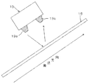
中間転写体用光センサ18は、中間転写体6の近傍であって2次転写対向ローラ10と2次転写ローラ13との対向位置近傍でかつ該対向位置よりも中間転写体6の搬送方向手前に配設されて、該中間転写体6の含水率を検出するセンサであり、転写材用光センサ19は、転写材15の近傍であって2次転写対向ローラ10と2次転写ローラ13との対向位置近傍でかつ該対向位置よりも転写材15の搬送方向手前に配設されて、該転写材15の含水率を検出するセンサである。例えば、転写材用光センサ19は、図2に示すように、転写材15の近傍であって2次転写対向ローラ10と2次転写ローラ13との対向位置近傍でかつ該対向位置よりも転写材15の搬送方向手前に配設されており、近赤外線光を転写材15に向かって発光する発光素子19aと、転写材15で反射された近赤外線光を受光する受光素子19bを備えている。この近赤外線光は、その波長が、0.8μm〜2.5μmの光であり、物質の含水率に応じて赤外線の反射量が大きく変化する性質を有している。したがって、転写材用光センサ19は、その発光素子19aから転写材15に向かって出射して該転写材15で反射された反射光の赤外線量を受光素子19bで受光することで、転写材15の含水率を検出することができる。
The intermediate transfer body
なお、図2では、転写材用光センサ19について示しているが、中間転写体用光センサ18についても同様の構成であり、ただ、中間転写体用光センサ18は、上述のように、中間転写体6の近傍であって2次転写対向ローラ10と2次転写ローラ13との対向位置近傍でかつ該対向位置よりも中間転写体6の搬送方向手前に配設されて、該中間転写体6の含水率を検出する。
Although FIG. 2 shows the transfer material
そして、これらの中間転写体用光センサ18及び転写材用光センサ19は、図3に転写材用光センサ19について示すように、転写材15の主走査方向(搬送方向に直交する方向)に複数(図3では、5個)並べて配設されており、各中間転写体用光センサ18及び各転写材用光センサ19の検出信号は、制御部17に送られて、制御部17のメモリ31にそれぞれ一旦格納される。
The intermediate transfer member
制御部17は、図3に示すように、CPU(Central Processing Unit )30とメモリ31を備えており、CPU(抵抗値調整手段、抵抗値算出手段)30が、上記各中間転写体用光センサ18及び各転写材用光センサ19に所定時間の間に複数回検出させてその複数回サンプリングさせたときの各中間転写体用光センサ18及び各転写材用光センサ19からの検出信号をメモリ(記憶手段)31に各光センサ18、19に対応させてそれぞれ保管する。そして、CPU30は、メモリ31に保管した各中間転写体用光センサ18の複数回のサンプリング含水率の総和を算出し、該総和をサンプリング回数で除算して平均含水率を算出する。そして、CPU30は、各中間転写体用光センサ18の複数回サンプリングの平均含水率の総和を算出し、該総和を中間転写体用光センサ18の個数で除算して、中間転写体6の平均含水率を算出して、中間転写体6の含水率とする。また、CPU30は、メモリ31に保管した各転写材用光センサ19の複数回のサンプリング含水率の総和を算出し、該総和をサンプリング回数で除算して平均含水率を算出する。そして、CPU30は、各転写材用光センサ19の複数回サンプリングの平均含水率の総和を算出して、該総和を転写材用光センサ19の個数で除算して、転写材15の平均含水率を算出して、転写材15の含水率とする。このメモリ31は、例えば、バッテリバックアップされたRAM(Random Access Memory)等の画像形成装置1の電源がオフの場合にも記憶内容を保持する不揮発性メモリが用いられている。
As shown in FIG. 3, the
また、上記対向ローラ用水分計20は、2次転写対向ローラ10と2次転写ローラ13との対向位置近傍でかつ該対向位置よりも2次転写対向ローラ10の回転方向手前の位置において該2次転写対向ローラ10に接触する状態で配設されて、該2次転写対向ローラ10の含水率を直接検出するセンサであり、転写ローラ用水分計21は、2次転写対向ローラ10と2次転写ローラ13との対向位置近傍でかつ該対向位置よりも2次転写ローラ13の回転方向手前の位置において該2次転写ローラ13に接触する状態で配設されて、該2次転写ローラ13の含水率を直接検出するセンサである。すなわち、対向ローラ用水分計20及び転写ローラ用水分計21は、中間転写体6上のトナー画像が転写材15上に転写される直前の位置で、2次転写対向ローラ10及び2次転写ローラ13の含水率を直接検出している。
Further, the moisture meter 20 for the counter roller is in the vicinity of the position where the secondary
これらの対向ローラ用水分計20及び転写ローラ用水分計21は、検出対象である2次転写対向ローラ10と2次転写ローラ13にそれぞれ直接接触して、該2次転写対向ローラ10と2次転写ローラ13の含水率を高精度に検出するため、複数回のサンプリングを必要としないが、該2次転写対向ローラ10及び2次転写ローラ13の検出位置によるばらつきを平均化させるために、2次転写対向ローラ10と2次転写ローラ13の主走査方向に複数並べて配設されている。すなわち、対向ローラ用水分計20及び転写ローラ用水分計21は、例えば、図4に転写ローラ用水分計21の場合について示すように、検出対象である2次転写対向ローラ10及び2次転写ローラ13の主走査方向(軸方向)に所定間隔で複数配設されている。画像形成装置1は、各対向ローラ用水分計20及び転写ローラ用水分計21の検出信号を制御部17のメモリ31に格納し、CPU30が、対向ローラ用水分計20及び転写ローラ用水分計21毎にその総和を算出する。そして、CPU30は、該総和と対向ローラ用水分計20及び転写ローラ用水分計21の個数に基づいて2次転写対向ローラ10及び2次転写ローラ13の平均含水率を算出して、2次転写対向ローラ10及び2次転写ローラ13の含水率としている。
These counter roller moisture meter 20 and transfer
そして、制御部17のCPU30は、上述のようにして、中間転写体6、転写材15、2次転写対向ローラ10及び2次転写ローラ13の含水率を検出すると、これらの含水率に基づいて転写部40の総抵抗値を算出し、該算出した転写部40の総抵抗値に基づいて、可変抵抗器16の抵抗値を制御して、転写電圧・電流を一定に制御する。
Then, when the
次に、本実施例の作用を説明する。本実施例の画像形成装置1は、中間転写体6、転写材15、2次転写対向ローラ10及び2次転写ローラ13の含水率を検出して、該含水率に基づいて2次転写対向ローラ10と接地との間の可変抵抗器16の抵抗値を制御している。
Next, the operation of this embodiment will be described. The image forming apparatus 1 according to the present exemplary embodiment detects the moisture content of the intermediate transfer body 6, the
画像形成装置1は、画像形成動作を開始すると、まず、画像データに基づいて感光体ベルト2上に静電潜像を形成して該静電潜像をトナーで現像してトナー画像を形成し、該感光体ベルト2上のトナー画像をバイアス部12からのバイアス電圧を1次転写印加ローラ7に印加して、感光体ベルト2上のトナー画像を中間転写体6に転写させる。画像形成装置1は、トナー画像の転写された中間転写体6を反時計方向に回転させつつ、該トナー画像を2次転写対向ローラ10と2次転写ローラ13との対向位置で2次転写ローラ13に2次転写電源14から2次転写電圧・電流を印加することで、中間転写体6上のトナー画像を、給紙部から中間転写体6と2次転写ローラ13との間に搬送されてくる転写材15に転写する。
When an image forming operation is started, the image forming apparatus 1 first forms an electrostatic latent image on the photosensitive belt 2 based on the image data, and develops the electrostatic latent image with toner to form a toner image. The toner image on the photosensitive belt 2 is applied with a bias voltage from the
そして、CPU30は、上記画像形成動作において、図5に示すように、転写材15が転写材用光センサ19の位置に搬送されてきたことを検出すると(ステップS101)、全ての光センサ18、19及び水分計20、21による検出を同時に開始させて、各光センサ18、19及び水分計20、21の検出した検出結果をメモリ31に格納する(ステップS102〜S105)。
When the
すなわち、CPU30は、転写材15の主走査方向に複数配設されている転写材用光センサ19で、転写材15の含水率をそれぞれ所定時間内に複数回サンプリングさせて検出させて、複数の転写材用光センサ19毎にまた複数回のサンプリング毎に、その含水率の検出結果をメモリ31に格納し、また、中間転写体6の主走査方向に複数配設されている中間転写体用光センサ18で、中間転写体6の含水率をそれぞれ所定時間内に複数回サンプリングさせて検出させて、複数の中間転写用光センサ18毎にまたサンプリング毎にその検出結果をメモリ31に格納する。また、CPU30は、2次転写対向ローラ10の軸方向(主走査方向)に複数配設されている対向ローラ用水分計20で、2次転写対向ローラ10の含水率をそれぞれ検出させて、複数の対向ローラ用水分計20毎にその検出結果をメモリ31に格納し、また、2次転写ローラ13の軸方向に複数配設されている転写ローラ用水分計21で、2次転写ローラ13の含水率をそれぞれ検出させて、複数の転写ローラ用水分計21毎にその検出結果をメモリ31に格納する。
That is, the
そして、CPU30は、転写材用光センサ19及び中間転写体用光センサ18は、それぞれ複数回含水率をサンプリングしているので、まず、メモリ31にサンプリング毎に及び転写材用光センサ19毎に格納されているサンプリングした複数回分の含水率検出信号を、転写材用光センサ19毎に、全て加算して総和を算出して、該総和を該サンプリング回数で除算して転写材用光センサ19のサンプリング1回当たりの平均含水率を算出し(ステップS106)、また、中間転写体用光センサ18毎に、該複数回分のサンプリング含水率検出信号を加算して総和を算出して、該総和を該サンプリング回数で除算して中間転写体用光センサ18の1回当たりの平均含水率を算出する(ステップS107)。
The
次に、CPU30は、複数の光センサ19、18及び水分計21、20の検出した含水率の平均含水率を算出する。すなわち、CPU30は、上記複数の転写材用光センサ19毎の複数回のサンプリングの平均含水率の総和を算出して、該総和を転写材用光センサ19の個数で除算することで、該複数の転写材用光センサ19の検出した転写材15の平均含水率を算出し(ステップS108)、また、上記中間転写体用光センサ18毎の複数回のサンプリングの平均含水率の総和を算出して、該総和を中間転写体用光センサ18の個数で除算することで、複数の中間転写体用光センサ18の検出した中間転写体6の平均含水率を算出する(ステップS109)。
Next, the
また、CPU30は、メモリ31に格納されている複数の転写ローラ用水分計21の検出結果の含水率の総和を算出して、該総和を転写ローラ用水分計21の個数で除算することで、転写ローラ用水分計21の検出した2次転写ローラ13の平均含水率を算出し(ステップS110)、また、メモリ31に格納されている複数の対向ローラ用水分計20の検出結果の含水率の総和を算出して、該総和を対向ローラ用水分計20の個数で除算することで、対向ローラ用水分計20の検出した2次転写対向ローラ10の平均含水率を算出する(ステップS111)。
Further, the
次に、CPU30は、上記算出した転写材15の平均含水率、中間転写体6の平均含水率、2次転写ローラ13の平均含水率及び2次転写対向ローラ10の平均含水率に基づいて、これらの転写材15、中間転写体6、2次転写ローラ13及び2次転写対向ローラ10を主要構成部品とする転写部40の含水率を求め、該転写部40の含水率に基づいて、該転写部40の総抵抗値を算出し(ステップS112)、該算出した転写部40の総抵抗値に基づいて、転写電圧・電流が所定の転写電圧・電流に一定となる可変抵抗器16の可変抵抗値を算出して、該可変抵抗値に設定制御する(ステップS113)。
Next, the
すなわち、転写材15、中間転写体6、2次転写ローラ13及び2次転写対向ローラ10で構成される転写部40の含水率が低い場合には、転写部40の抵抗値が上昇するので、転写電圧・電流を一定にするために、可変抵抗器16の可変抵抗値を比較的小さく設定し、逆に、転写部40の含水率が高い場合には、転写部40の抵抗値が低下するので、転写電圧・電流を一定にするために、可変抵抗器16の可変抵抗値を比較的大きく設定する。すなわち、環境が変化して転写部40の構成部品の抵抗が変化しても、転写部40の総抵抗が予め設定された抵抗値になるように可変抵抗器16の可変抵抗値を調整し、転写電圧・電流を常に同じ条件に調整する。
That is, when the moisture content of the
なお、上記実施例の画像形成装置1は、感光体ベルト2上に形成したトナー画像を中間転写体6を介して転写材15に転写する方式に適用したものであるが、画像形成方式としては、上記方式に限るものではなく、例えば、感光体上に形成したトナー画像を直接転写材上に転写する方式の画像形成装置であってもよい。
The image forming apparatus 1 of the above embodiment is applied to a system in which the toner image formed on the photoreceptor belt 2 is transferred to the
また、上記説明では、画像形成装置1が白黒画像を形成するものとして説明しているが、カラー画像を形成する場合にも同様に適用することができる。この場合、例えば、画像形成装置1は、上記感光体ベルト2上に複数色の画像データで変調された書込光を照射して複数色用の静電潜像を順次形成し、該複数色の静電潜像を対応する色のトナーで現像して、各色のトナー画像を順次感光体ベルト2上に形成する。そして、画像形成装置1は、この感光体ベルト2上の複数色のトナー画像を、中間転写体6に順次重ね合わせて転写して、カラーのトナー画像を中間転写体6上に形成し、このカラーのトナー画像を、上記同様に、2次転写対向ローラ10と2次転写ローラ13との間で転写材15に転写する。画像形成装置1は、この中間転写体6上のカラーのトナー画像の転写材15への転写において、上記同様に、転写部40の総抵抗値を構成部品の含水率に基づいて算出して、該転写部40の総抵抗値に基づいて可変抵抗器16の可変抵抗値を調整し、転写電圧・電流を一定にする。
In the above description, the image forming apparatus 1 is described as forming a black and white image, but the present invention can be similarly applied to the case of forming a color image. In this case, for example, the image forming apparatus 1 sequentially forms an electrostatic latent image for a plurality of colors by irradiating the photosensitive belt 2 with writing light modulated with a plurality of colors of image data. The electrostatic latent images are developed with corresponding color toners, and toner images of the respective colors are sequentially formed on the photosensitive belt 2. Then, the image forming apparatus 1 sequentially superimposes and transfers the toner images of a plurality of colors on the photosensitive belt 2 onto the intermediate transfer member 6 to form a color toner image on the intermediate transfer member 6. The color toner image is transferred to the
また、上記説明では、転写部40の総抵抗値を算出するのに、中間転写体6、転写材15、2次転写対向ローラ10及び2次転写ローラ13の全ての含水率を検出しているが、これら転写部40を構成する全ての構成部品の含水率を検出するものに限るものではなく、主要な構成部品の1つまたは複数の含水率を検出して、転写部40の総抵抗値を求め、可変抵抗器16の可変抵抗値を決定するようにしてもよい。
In the above description, in order to calculate the total resistance value of the
さらに、転写部40の構成部品の含水率の検出方法は、上記検出方法に限るものではない。
Furthermore, the method for detecting the moisture content of the components of the
このように、本実施例の画像形成装置1は、中間転写体(像担持体)6上のトナー画像を転写材15に転写する転写部40の総抵抗値を検出して、該検出した転写部40の総抵抗値に基づいて、転写部40の接地間に接続されている可変抵抗器16の抵抗値を調整している。
As described above, the image forming apparatus 1 according to the present embodiment detects the total resistance value of the
したがって、転写部40の総抵抗値を適切に検出して、転写電圧・電流を常に同じ条件に調整することができ、転写性能を向上させて、画像品質を向上させることができる。
Accordingly, it is possible to appropriately detect the total resistance value of the
また、本実施例の画像形成装置1は、感光体ベルト2上に形成されたトナー画像を像担持体としての中間転写体6上に転写して、中間転写体6上のトナー画像を転写部40で転写材15に転写している。
Further, the image forming apparatus 1 of this embodiment transfers the toner image formed on the photosensitive belt 2 onto an intermediate transfer member 6 as an image carrier, and transfers the toner image on the intermediate transfer member 6 to a transfer unit. 40 is transferred to the
したがって、感光体上のトナー画像を直接転写材に転写する画像形成方式の画像形成装置だけでなく、感光体ベルト2上のトナー画像を中間転写体6に一次転写し、この中間転写体6上のトナー画像を転写材15に2次転写する方式の画像形成装置に対しても適用することができ、汎用性を向上させることができる。
Accordingly, not only the image forming apparatus that directly transfers the toner image on the photosensitive member to the transfer material, but also the toner image on the photosensitive belt 2 is primarily transferred to the intermediate transfer member 6. The toner image can be applied to an image forming apparatus that secondarily transfers the toner image to the
さらに、本実施例の画像形成装置1は、転写部抵抗値検出手段として、転写部40を構成する転写部構成手段としての転写材15、中間転写体6、2次転写ローラ13及び2次転写対向ローラ10の含水率を中間転写体用光センサ18、転写材用光センサ19、対向ローラ用水分計20及び転写ローラ用水分計21で検出し、制御部17のCPU30が、該含水率検出結果に基づいて転写部40の総抵抗値を算出している。
Furthermore, the image forming apparatus 1 according to the present exemplary embodiment is configured such that the
したがって、転写部40の総抵抗値に最も影響する含水率を、適切に検出して、転写部40の総抵抗値を算出することができ、適切な転写電圧・電流を供給して、転写性能を向上させて、画像品質を向上させることができる。
Therefore, it is possible to appropriately detect the water content that most affects the total resistance value of the
また、本実施例の画像形成装置1は、検出対象の含水率に応じてその反射量の変化する近赤外線を用いた光センサ18、19を用いている。特に、中間転写体用光センサ18を用いて中間転写体6の含水率を検出し、転写材用光センサ19を用いて転写材15の含水率を検出している。
Further, the image forming apparatus 1 of the present embodiment uses
したがって、中間転写体6上のトナー画像や転写材15上に転写されたトナー画像に傷を付けることなく、適切に含水率を測定することができ、画像品質をより一層向上させることができる。
Therefore, it is possible to appropriately measure the moisture content without damaging the toner image on the intermediate transfer body 6 or the toner image transferred onto the
さらに、本実施例の画像形成装置1は、検出対象に接触して該検出対象の含水率を直接検出する対向ローラ用水分計20及び転写ローラ用水分計21で2次転写対向ローラ10及び2次転写ローラ13の含水率を検出している。
Further, the image forming apparatus 1 according to the present embodiment includes the counter transfer moisture meter 20 and the transfer
したがって、転写部40の構成部品である2次転写対向ローラ10及び2次転写ローラ13の含水率をより一層正確に検出することができ、より一層適切に転写部40の総抵抗値を算出して、可変抵抗器16の抵抗値をより一層適切な抵抗値に調整することができる。その結果、より一層転写性能を向上させることができ、より一層画像品質を向上させることができる。
Therefore, the moisture content of the secondary
また、本実施例の画像形成装置1は、中間転写体用光センサ18、転写材用光センサ19、対向ローラ用水分計20及び転写ローラ用水分計21をそれぞれ主走査方向に複数配設している。
In the image forming apparatus 1 of the present embodiment, a plurality of intermediate transfer member
したがって、検出対象の転写材15、中間転写体6、2次転写ローラ13及び2次転写対向ローラ10の位置による含水率のばらつきを適切に検出して全体の含水率を正確に検出することができ、より一層適切に転写部40の総抵抗値を算出して、可変抵抗器16の抵抗値をより一層適切な抵抗値に調整することができる。
Therefore, it is possible to detect the variation of the moisture content depending on the positions of the
さらに、本実施例の画像形成装置1は、CPU30が、複数の中間転写体用光センサ18、転写材用光センサ19、対向ローラ用水分計20及び転写ローラ用水分計21それぞれの検出結果の含水率から平均含水率を算出し、該平均含水率に基づいて転写部40の総抵抗値を算出している。
Furthermore, in the image forming apparatus 1 of the present embodiment, the
したがって、検出対象の転写材15、中間転写体6、2次転写ローラ13及び2次転写対向ローラ10のそれぞれの全体の含水率を正確に検出することができ、より一層適切に転写部40の総抵抗値を算出して、可変抵抗器16の抵抗値をより一層適切な抵抗値に調整することができる。
Accordingly, it is possible to accurately detect the entire moisture content of each of the
また、本実施例の画像形成装置1は、中間転写体用光センサ18と転写材用光センサ19での含水率の検出を、所定時間内に複数回を行い、CPU30が、該複数回の含水率検出結果から平均含水率を算出し、該平均含水率に基づいて転写部40の総抵抗値を算出している。
Further, in the image forming apparatus 1 of the present embodiment, the moisture content is detected by the intermediate transfer member
したがって、検出対象の転写材15及び中間転写体6のそれぞれ含水率を正確に検出することができ、より一層適切に転写部40の総抵抗値を算出して、可変抵抗器16の抵抗値をより一層適切な抵抗値に調整することができる。
Therefore, the moisture content of each of the
さらに、本実施例の画像形成装置1は、中間転写体用光センサ18、転写材用光センサ19、対向ローラ用水分計20及び転写ローラ用水分計21の検出結果を制御部17のメモリ31に格納して、CPU30が該メモリ31内の検出結果から平均含水率を算出している。
Further, the image forming apparatus 1 according to the present exemplary embodiment uses the detection results of the intermediate transfer member
したがって、検出対象の転写材15、中間転写体6、2次転写ローラ13及び2次転写対向ローラ10のそれぞれの含水率を正確に検出することができ、より一層適切に転写部40の総抵抗値を算出して、可変抵抗器16の抵抗値をより一層適切な抵抗値に調整することができる。
Therefore, it is possible to accurately detect the moisture content of each of the
また、本実施例の画像形成装置1は、中間転写体用光センサ18、転写材用光センサ19、対向ローラ用水分計20及び転写ローラ用水分計21、特に、対向ローラ用水分計20及び転写ローラ用水分計21が、トナー画像の転写材15への転写位置近傍であって、転写材15、中間転写体6、2次転写ローラ13及び2次転写対向ローラ10の転写位置への移動方向手前の位置に配設されている。
Further, the image forming apparatus 1 of the present embodiment includes an intermediate transfer member
したがって、転写タイミング直前での含水率を検出することができ、転写部40の総抵抗値を算出して、可変抵抗器16の抵抗値を調整することができる。その結果、より一層転写性能を向上させることができ、画像品質をより一層向上させることができる。
Therefore, the moisture content immediately before the transfer timing can be detected, the total resistance value of the
さらに、本実施例の画像形成装置1は、全ての中間転写体用光センサ18、転写材用光センサ19、対向ローラ用水分計20及び転写ローラ用水分計21で一斉に転写材15、中間転写体6、2次転写ローラ13及び2次転写対向ローラ10の含水率を検出している。
Further, the image forming apparatus 1 according to the present embodiment includes all of the intermediate transfer member
したがって、含水率の検出時間の変化による転写材15、中間転写体6、2次転写ローラ13及び2次転写対向ローラ10の含水率の誤差を削減することができ、より一層正確に転写部40の総抵抗値を算出して、可変抵抗器16の抵抗値をより一層適切な抵抗値に調整することができる。その結果、より一層転写性能を向上させて、画像品質をより一層向上させることができる。
Therefore, it is possible to reduce errors in the moisture content of the
また、本実施例の画像形成装置1は、転写材15が転写位置近傍に搬送されてきたタイミングで全ての中間転写体用光センサ18、転写材用光センサ19、対向ローラ用水分計20及び転写ローラ用水分計21で同時に転写材15、中間転写体6、2次転写ローラ13及び2次転写対向ローラ10の含水率を検出している。
Further, in the image forming apparatus 1 of the present embodiment, all of the intermediate transfer member
したがって、含水率の検出時間の変化による含水率の誤差を削減することができるとともに、転写タイミング直前での転写部40の総抵抗値をより正確に算出して、可変抵抗器16の抵抗値をより一層適切な抵抗値に調整することができる。その結果、より一層転写性能を向上させて、画像品質をより一層向上させることができる。
Accordingly, it is possible to reduce the moisture content error due to the change in the moisture content detection time, and more accurately calculate the total resistance value of the
以上、本発明者によってなされた発明を好適な実施例に基づき具体的に説明したが、本発明は上記のものに限定されるものではなく、その要旨を逸脱しない範囲で種々変更可能であることはいうまでもない。 The invention made by the present inventor has been specifically described based on the preferred embodiments. However, the present invention is not limited to the above, and various modifications can be made without departing from the scope of the invention. Needless to say.
本発明は、転写部で現像剤像を転写材に転写して画像形成するプリンタ装置、複写装置、複合装置等の画像形成装置に適用することができる。 The present invention can be applied to an image forming apparatus such as a printer, a copying apparatus, or a composite apparatus that forms an image by transferring a developer image onto a transfer material in a transfer unit.
1 画像形成装置
2 感光体ベルト
3 1次転写対向ローラ
4 感光体ベルト駆動ローラ
5 搬送ローラ
6 中間転写体
7 1次転写印加ローラ
8 中間転写駆動ローラ
9 中間転写体テンションローラ
10 2次転写対向ローラ
11 ベルトクリーニング対向ローラ
12 1次転写バイアス部
13 2次転写ローラ
14 2次転写電源
15 転写材
16 可変抵抗器
17 制御部
18 中間転写体用光センサ
19 転写材用光センサ
20 対向ローラ用水分計
21 転写ローラ用水分計
19a 発光素子
19b 受光素子
30 CPU
31 メモリ
40 転写部
DESCRIPTION OF SYMBOLS 1 Image forming apparatus 2 Photoconductor belt 3 Primary transfer counter roller 4 Photoconductor belt drive roller 5 Conveyance roller 6
31
Claims (12)
Priority Applications (1)
| Application Number | Priority Date | Filing Date | Title |
|---|---|---|---|
| JP2007108755A JP2008268385A (en) | 2007-04-17 | 2007-04-17 | Image forming apparatus |
Applications Claiming Priority (1)
| Application Number | Priority Date | Filing Date | Title |
|---|---|---|---|
| JP2007108755A JP2008268385A (en) | 2007-04-17 | 2007-04-17 | Image forming apparatus |
Publications (1)
| Publication Number | Publication Date |
|---|---|
| JP2008268385A true JP2008268385A (en) | 2008-11-06 |
Family
ID=40048005
Family Applications (1)
| Application Number | Title | Priority Date | Filing Date |
|---|---|---|---|
| JP2007108755A Pending JP2008268385A (en) | 2007-04-17 | 2007-04-17 | Image forming apparatus |
Country Status (1)
| Country | Link |
|---|---|
| JP (1) | JP2008268385A (en) |
Cited By (4)
| Publication number | Priority date | Publication date | Assignee | Title |
|---|---|---|---|---|
| CN102023537A (en) * | 2009-09-18 | 2011-04-20 | 佳能株式会社 | Image forming apparatus |
| JP2015187723A (en) * | 2014-03-14 | 2015-10-29 | 株式会社リコー | image forming apparatus |
| WO2017179248A1 (en) * | 2016-04-11 | 2017-10-19 | シャープ株式会社 | Image forming device and image forming method |
| US10197940B2 (en) | 2016-12-27 | 2019-02-05 | Canon Kabushiki Kaisha | Image forming apparatus changing magnitude of control signal used for image formation |
Citations (4)
| Publication number | Priority date | Publication date | Assignee | Title |
|---|---|---|---|---|
| JPS63136069A (en) * | 1986-11-28 | 1988-06-08 | Fuji Xerox Co Ltd | Transfer device for electrophotographic copying machine |
| JPH0756402A (en) * | 1993-08-16 | 1995-03-03 | Ricoh Co Ltd | Image forming device with humidity detecting function |
| JP2006053398A (en) * | 2004-08-12 | 2006-02-23 | Sanyo Electric Co Ltd | Image forming apparatus |
| JP2006091322A (en) * | 2004-09-22 | 2006-04-06 | Ricoh Co Ltd | Image forming apparatus |
-
2007
- 2007-04-17 JP JP2007108755A patent/JP2008268385A/en active Pending
Patent Citations (4)
| Publication number | Priority date | Publication date | Assignee | Title |
|---|---|---|---|---|
| JPS63136069A (en) * | 1986-11-28 | 1988-06-08 | Fuji Xerox Co Ltd | Transfer device for electrophotographic copying machine |
| JPH0756402A (en) * | 1993-08-16 | 1995-03-03 | Ricoh Co Ltd | Image forming device with humidity detecting function |
| JP2006053398A (en) * | 2004-08-12 | 2006-02-23 | Sanyo Electric Co Ltd | Image forming apparatus |
| JP2006091322A (en) * | 2004-09-22 | 2006-04-06 | Ricoh Co Ltd | Image forming apparatus |
Cited By (6)
| Publication number | Priority date | Publication date | Assignee | Title |
|---|---|---|---|---|
| CN102023537A (en) * | 2009-09-18 | 2011-04-20 | 佳能株式会社 | Image forming apparatus |
| JP2015187723A (en) * | 2014-03-14 | 2015-10-29 | 株式会社リコー | image forming apparatus |
| WO2017179248A1 (en) * | 2016-04-11 | 2017-10-19 | シャープ株式会社 | Image forming device and image forming method |
| JPWO2017179248A1 (en) * | 2016-04-11 | 2019-02-21 | シャープ株式会社 | Image forming apparatus and image forming method |
| US10591859B2 (en) | 2016-04-11 | 2020-03-17 | Sharp Kabushiki Kaisha | Image forming device and image forming method |
| US10197940B2 (en) | 2016-12-27 | 2019-02-05 | Canon Kabushiki Kaisha | Image forming apparatus changing magnitude of control signal used for image formation |
Similar Documents
| Publication | Publication Date | Title |
|---|---|---|
| US9977361B2 (en) | Image forming apparatus and image forming system | |
| US7697854B2 (en) | Image forming apparatus with variable process speed | |
| JP6137615B2 (en) | Image forming apparatus and image density control method | |
| JP4241759B2 (en) | Image forming apparatus and density control method for image forming apparatus | |
| US8369725B2 (en) | Image forming apparatus and method of correcting image concentration | |
| US20080124108A1 (en) | Image forming apparatus | |
| US8078069B2 (en) | Image forming apparatus and image forming method | |
| JP4890810B2 (en) | Image forming apparatus | |
| US9927756B2 (en) | Image forming apparatus, image formation system, density-unevenness correction method and recording medium | |
| US20130221205A1 (en) | Light amount detector and image forming apparatus | |
| JP5277577B2 (en) | Image forming apparatus and program | |
| JP4443589B2 (en) | Developing device and image forming apparatus having the same | |
| US7865095B2 (en) | Image forming apparatus including distance detection unit | |
| JP2008268385A (en) | Image forming apparatus | |
| US20180107145A1 (en) | Image forming apparatus and a recording medium | |
| US7433616B2 (en) | Image forming apparatus including a controlling section | |
| JP2016167007A (en) | Image forming apparatus and control method of image forming apparatus | |
| US10527995B1 (en) | Image forming apparatus having abnormality detection unit for humidity sensor | |
| JP3770088B2 (en) | Image forming apparatus | |
| JP2006065183A (en) | Image forming apparatus | |
| US9513585B2 (en) | Image forming apparatus which sets image forming condition based on calculated exposed area potential | |
| JP2008122813A (en) | Image forming apparatus and density detection method therefor | |
| JP2002214854A (en) | Image forming apparatus | |
| JP2005337749A (en) | Reflected light sensing method and image forming apparatus | |
| US9116123B2 (en) | Gloss measuring device and image forming device including same |
Legal Events
| Date | Code | Title | Description |
|---|---|---|---|
| A621 | Written request for application examination |
Free format text: JAPANESE INTERMEDIATE CODE: A621 Effective date: 20100126 |
|
| A521 | Written amendment |
Free format text: JAPANESE INTERMEDIATE CODE: A821 Effective date: 20100208 |
|
| RD02 | Notification of acceptance of power of attorney |
Free format text: JAPANESE INTERMEDIATE CODE: A7422 Effective date: 20100208 |
|
| A02 | Decision of refusal |
Free format text: JAPANESE INTERMEDIATE CODE: A02 Effective date: 20120410 |