JP2008264515A - Dental tape and process for obtaining dental tape - Google Patents
Dental tape and process for obtaining dental tape Download PDFInfo
- Publication number
- JP2008264515A JP2008264515A JP2008071048A JP2008071048A JP2008264515A JP 2008264515 A JP2008264515 A JP 2008264515A JP 2008071048 A JP2008071048 A JP 2008071048A JP 2008071048 A JP2008071048 A JP 2008071048A JP 2008264515 A JP2008264515 A JP 2008264515A
- Authority
- JP
- Japan
- Prior art keywords
- dental tape
- dental
- indentations
- tape
- tape according
- Prior art date
- Legal status (The legal status is an assumption and is not a legal conclusion. Google has not performed a legal analysis and makes no representation as to the accuracy of the status listed.)
- Pending
Links
Images


Classifications
-
- A—HUMAN NECESSITIES
- A61—MEDICAL OR VETERINARY SCIENCE; HYGIENE
- A61C—DENTISTRY; APPARATUS OR METHODS FOR ORAL OR DENTAL HYGIENE
- A61C15/00—Devices for cleaning between the teeth
- A61C15/04—Dental floss; Floss holders
- A61C15/041—Dental floss
- A61C15/042—Dental floss comprising protuberances along its length, e.g. balls or knots
Abstract
Description
〔発明の分野〕
本発明は、歯間空間からバイオフィルム(歯垢)および食べかすを取り去るための歯間掃除手段として使用される単繊維デンタルテープと、このような単繊維デンタルテープを得るための製法とに関するものである。
(Field of the Invention)
The present invention relates to a single fiber dental tape used as an interdental cleaning means for removing biofilm (plaque) and food residue from an interdental space, and a production method for obtaining such a single fiber dental tape. is there.
〔発明の背景〕
歯間空間において手で使用されている間、より糸として一つに保たれている複数のフィラメントによって形成されたデンタルフロスが従来技術において公知である。歯の隣接した壁部に対するフロスの摩擦運動で、別々のフィラメントは徐々にバラバラになり、つまり、互いに引き離され、デンタルフロスで食べかすを除去する能力をより大きくする。
BACKGROUND OF THE INVENTION
Dental floss formed by a plurality of filaments held together as a strand while being used by hand in the interdental space is known in the prior art. With the frictional movement of the floss against the adjacent walls of the teeth, the separate filaments gradually fall apart, i.e. they are separated from each other, increasing the ability to remove the meal with dental floss.
このようなマルチフィラメントは、歯間空間で擦られるまでは一つに保たれている。このようなマルチフィラメントからなるデンタルフロスは、広く使用されており、歯間空間に挿入しやすくはあるが、歯の表面を擦る、または、削るという操作中にマルチフィラメントが引き離される、すなわち、バラバラになることが可能であり、使用者の歯のくぼみほどの大きさになり、使用者にとって不快となるという不都合がある。 Such multifilaments are kept together until they are rubbed in the interdental space. Such a dental floss made of multifilament is widely used and can be easily inserted into the interdental space, but the multifilament is separated during the operation of rubbing or scraping the tooth surface. There is a disadvantage that it becomes as large as a dent of the user's teeth and is uncomfortable for the user.
上記の不都合に加え、このようなマルチフィラメントからなるデンタルフロスは、比較的多量の結合剤を付けることが必要である。しかしながら、結合剤の量が多すぎると、大なり小なり、歯間空間で使用中のフロスの柔軟特性を損ねることがあり、さらに、単位長さ当たり、より多くの原材料が必要となる。 In addition to the above disadvantages, such a dental floss composed of multifilaments requires a relatively large amount of binder. However, if the amount of binder is too large, it can be greater or lesser, which can impair the flexible properties of the floss in use in the interdental space, and more raw material is required per unit length.
これら歯間の補助的な掃除要素の他の構造は、ポリオレフィン、ポリアミド、ポリエステル、および、ポリテトラフルオロエチレン(PTFE)などのフルオロポリマーといったプラスチック材料から押し出し成形されたフィルムから一般に得られる単繊維で形成された、矩形断面を有する既知のデンタルテープで定められる。これらのテープは、単繊維であり、それ故に一体であるため、歯間空間で擦られたときに、引き離されやすい、つまり、ほつれやすいという不都合がない。 Other structures of these interdental auxiliary cleaning elements are monofilaments generally obtained from films extruded from plastic materials such as polyolefins, polyamides, polyesters, and fluoropolymers such as polytetrafluoroethylene (PTFE). It is defined by a known dental tape formed with a rectangular cross section. Since these tapes are monofilaments and are therefore integral, there is no inconvenience that they are easily pulled apart, that is, frayed easily when rubbed in the interdental space.
既知の単繊維デンタルテープは、マルチフィラメントのデンタルフロスにおける隙間の表面積(interstitial surface area)に比べて、表面積が小さい。表面積が小さいので、歯間空間からバイオフィルムおよびかすを除去する能力または効力が低い。さらに、隙間という見地からのこれら既知の単繊維デンタルテープの表面積の減少により、研磨機能、殺菌機能、香味機能等のある添加剤を組み入れる媒体として作用する結合剤を凝集させるという単繊維デンタルテープの能力が低くなる。さらに、これら単繊維デンタルテープは滑らかであるので、把持特性も悪く、デンタルフロスで掃除をしている間、指に適切に保持されるとの感覚を使用者に与えるものではない。 Known monofilament dental tapes have a small surface area compared to the interstitial surface area in multifilament dental floss. Because of the small surface area, the ability or efficacy to remove biofilm and debris from the interdental space is low. Furthermore, by reducing the surface area of these known single fiber dental tapes from the standpoint of gaps, single fiber dental tapes that agglomerate binders that act as media for incorporating certain additives such as polishing, bactericidal, and flavoring functions. Ability is lowered. Furthermore, since these single fiber dental tapes are smooth, they have poor gripping properties and do not give the user a sense that they are properly held by the fingers while cleaning with dental floss.
滑らかな表面をした既知の単繊維デンタルテープは、たとえば、既知の把持向上特性を有する種々のワックスからなる少量の表面被覆という形態で、比較的少量の結合剤しか受け付けないという特性を有する。上記の滑らかな単繊維テープが表面被覆の形成に用いられる結合剤の量に課す制約は、結合剤が備えるべき、香味、研磨、殺菌等の種々の活性機能を有する補足的な添加剤の量の望ましくない制限につながる。 Known monofilament dental tapes with a smooth surface have the property that they accept only a relatively small amount of binder, for example in the form of a small amount of a surface coating consisting of various waxes with known grip-enhancing properties. The constraints imposed on the amount of binder used by the smooth monofilament tape described above to form the surface coating are the amount of supplemental additives that the binder should have and have various active functions such as flavor, polishing, sterilization, etc. Leading to undesirable restrictions.
デンタルフロスを把持しやすくするように、また、活性機能を有する種々の添加剤の担体としても機能するように、たとえば微晶質ワックスのような摩擦向上ワックスを用いた表面被覆を有する滑らかなデンタルフロスが、米国特許第5,209,251号に開示されている。このような滑らかなデンタルフロス、特に単繊維のデンタルフロスでは、結合剤からできた表面被覆が、デンタルフロスを適切につかめるようにし、また、表面被覆に備えられた、研磨機能を有する添加剤により、かすを擦り、除去する所望の能力をも付与可能にするための基礎となっている。テープに安定的に組み込むことができる結合剤の量の限界が、活性機能がある添加剤の担体としての表面被覆の機能における効率に望ましくない制限を加える。 Smooth dental with a surface coating using a friction-enhancing wax, such as microcrystalline wax, to make it easier to grip dental floss and as a carrier for various active additives Floss is disclosed in US Pat. No. 5,209,251. In such a smooth dental floss, especially a single fiber dental floss, the surface coating made of the binder ensures that the dental floss can be properly grasped, and the surface coating is provided with an additive having a polishing function. This is the basis for making it possible to impart the desired ability to rub and remove debris. The limit on the amount of binder that can be stably incorporated into the tape adds an undesirable limit to the efficiency in the function of the surface coating as a carrier of active additives.
米国特許第4,646,766号(以下’766特許という)は、たとえばポリプロピレンフィルムから得られた、最初から/若干の小繊維化が可能な所定の長さの単繊維によって構成されたデンタルテープを開示している。このようなフィルムは、歯の表面にこすりつけると自然に小繊維に分離する密着した(coherent)フィルムであり、また、既に小繊維に分離していて一時的に安定したフィルムを含む。’766特許に記載のこの構造的解決法では、プラスチックテープが受けるエンボス加工が、歯間空間で摩擦を受けたときに、小繊維に分離する、すなわち、小さい、予め定められた水準にバラバラになる特性をテープに与えるという目的で定められ、かつ、この目的に合わせてある。このように小繊維に分離すると、バイオフィルム(歯垢)およびかすを除去する能力が高くなるが、このような歯間空間内での小繊維化は、使用者にとっての不快の一因となる。 U.S. Pat. No. 4,646,766 (hereinafter referred to as the '766 patent) is a dental tape made of a single fiber of a predetermined length, for example, obtained from a polypropylene film and capable of being slightly / smallly fibrillated from the beginning. Is disclosed. Such films include coherent films that naturally separate into fibrils when rubbed against the tooth surface, and also include films that have already separated into fibrils and are temporarily stable. In this structural solution described in the '766 patent, the embossing experienced by the plastic tape separates into small fibers when subjected to friction in the interdental space, i.e., falls apart to a small, predetermined level. The purpose is to give the tape the following characteristics and is tailored to this purpose. Such separation into fibrils increases the ability to remove biofilm (plaque) and debris, but such fibrillation within the interdental space contributes to user discomfort. .
小繊維に分離することに関連した不都合に加え、この従来技術のポリマーテープは、把持向上手段として、また、研磨機能、香味機能、殺菌機能等のある添加剤の担体としても作用させるために、テープに適切かつ安定的に組み入れることができる表面結合剤の量を制限する点で、単繊維テープに関して前述したのと同じ欠点を有する。 In addition to the inconvenience associated with separating into small fibers, this prior art polymer tape acts as a gripping enhancement means and also as a carrier for certain additives such as polishing function, flavor function, bactericidal function, etc. It has the same disadvantages as described above for monofilament tapes in that it limits the amount of surface binder that can be properly and stably incorporated into the tape.
米国特許第5,657,779号は、特にデンタルテープを形成するための細長いPTFEフィルムを形成するための方法および装置について記述している。記述されている方法の目的は、使用中にテープが小繊維に分離することを減らすか回避し、また、さまざまなコーティング、たとえば、研磨剤、殺菌剤、香味剤等の他の添加剤を備えたワックスを受けやすいPTFEデンタルテープを生産することである。使用中の小繊維化は減少するが、表面積が断面の輪郭に制限されるこの従来技術の単繊維デンタルテープもまた、握りやすくするために表面結合剤を塗布する必要があるが、その量は、その表面結合剤が保持すべき種々の添加剤の量に対する制限をもたらすことがあるという欠点を有する。 U.S. Pat. No. 5,657,779 describes a method and apparatus for forming an elongated PTFE film, particularly for forming dental tape. The purpose of the described method is to reduce or avoid the separation of the tape into fibrils during use, and with various coatings such as abrasives, bactericides, flavoring agents and other additives. It is to produce PTFE dental tape that is easily subjected to wax. This prior art monofilament dental tape, which reduces fibrillation during use, but whose surface area is limited to the cross-sectional profile, also requires the application of a surface binder to make it easier to grip, but the amount is Has the disadvantage that the surface binder may result in limitations on the amount of various additives to be retained.
上述したように、単繊維デンタルテープは公知であるが、歯間空間に挿入しやすく、使用者による握りが改善され、既知の結合剤を用いた場合も、用いない場合も、テープへの添加剤の塗布および保持が改善され、小繊維に分離することを防ぐことで使用者の快適が保たれ、以上全てが物理的、機械的特性を損なうことなく行われる単繊維デンタルテープに対する需要がまだある。本発明のデンタルテープは、このような特徴を提供するものである。 As mentioned above, monofilament dental tape is known, but it is easy to insert into the interdental space, the grip by the user is improved, and it can be added to the tape whether or not a known binder is used. There is still a need for monofilament dental tape that improves the application and retention of the agent, keeps the user comfortable by preventing separation into fibrils, all without any loss of physical and mechanical properties is there. The dental tape of the present invention provides such a feature.
〔発明の概要〕
本発明は、単繊維デンタルテープを含み、この単繊維デンタルテープは、第一の外面、および、第一の外面とは反対側の第二の外面を有する芯体(core body)を備えており、第一および第二の外面の少なくとも一方は、デンタルテープの芯体内へと突き出す複数のくぼみを有する。複数のくぼみは、第一および第二の外面の少なくとも一方の全面積の約5%から約95%に設けられている。複数のくぼみを備えた第一および第二の外面の少なくとも一方に関して、くぼみは芯体内の深さを有し、この深さは、複数のくぼみを備えた第一および第二の外面の少なくとも一方に対して横断するようにとった芯体の厚みの約0.1%から約95%に相当する。
[Summary of the Invention]
The present invention includes a monofilament dental tape, the monofilament dental tape comprising a core body having a first outer surface and a second outer surface opposite the first outer surface. At least one of the first and second outer surfaces has a plurality of indentations that protrude into the core of the dental tape. The plurality of indentations are provided in about 5% to about 95% of the total area of at least one of the first and second outer surfaces. With respect to at least one of the first and second outer surfaces with a plurality of indentations, the indentation has a depth within the core, the depth being at least one of the first and second outer surfaces with the plurality of indentations. This corresponds to about 0.1% to about 95% of the thickness of the core taken so as to cross.
本発明の可能性のある実施形態の例として添付図面を参照しながら、本発明を以下に説明する。 The present invention will now be described by way of example with reference to the accompanying drawings as examples of possible embodiments of the invention.
〔発明の詳細な説明〕
本発明は、押し出し成形したプラスチックフィルムから簡単に得ることができる、伸ばすことのできない単繊維デンタルテープを提供するものである。このデンタルテープは、前述したくぼみのない同様の単繊維テープの同じ特性と比べて、高い機械的強度を提供し、柔軟性、使用者のつかみ易さに関する特性がよく、さらに、歯間空間から歯垢およびかすを除去する能力が向上しており、単繊維が小繊維に分離することがない。
Detailed Description of the Invention
The present invention provides a non-stretchable single fiber dental tape that can be easily obtained from an extruded plastic film. This dental tape provides higher mechanical strength, better flexibility and ease of gripping for users compared to the same properties of similar monofilament tapes without dents as described above. The ability to remove plaque and debris is improved and single fibers do not separate into fibrils.
本発明はまた、前述したくぼみのない同様の単繊維テープの同じ特性と比べて、表面積がかなり増えており、また、香味、殺菌、研磨、感覚知(sensate)、催唾液、着色、芳香付け、治療等の、歯間空間の掃除と異なる機能を備えたデンタルテープを提供するのに必要なことがある表面被覆を固定させる能力がかなり高くなっている単繊維デンタルテープを提供する。 The present invention also has a significantly increased surface area compared to the same properties of similar monofilament tapes without dents described above, and also has flavor, sterilization, polishing, sensate, salivation, coloring, aromatization. A monofilament dental tape is provided that has a much higher ability to secure a surface coating that may be required to provide a dental tape with a different function from interdental space cleaning, such as treatment.
上述した概略構造は、小型で滑らかな構造の単繊維デンタルテープを提供するものであり、このデンタルテープは、触った感触がよく、使用者に対して好適な把持特性を提供し、また、くぼみを設けたことにより、歯間空間からバイオフィルムおよびかすを取り除く能力が高く、このくぼみの固定能力により、任意の結合剤をデンタルテープの基材に「安定的」に結びつけることができる。 The above-described schematic structure provides a single-fiber dental tape having a small and smooth structure. This dental tape has a good touch feel, provides a gripping characteristic suitable for the user, and is indented. The ability to remove biofilm and debris from the interdental space is high, and the ability to fix the dent makes it possible to bind any binder to the dental tape substrate in a “stable” manner.
前述したように、本発明の目的は、好ましくはPTFEであるプラスチックフィルムから形成したデンタルテープ10を、掃除、把持、表面被覆の固定、および、柔軟性についての特性がよいデンタルテープを製造できる、簡単で比較的低価格な製法で提供することである。
As described above, the object of the present invention is to produce a dental tape having good properties for cleaning, gripping, fixing a surface coating, and flexibility with respect to a
PTFEは、デンタルテープを形成するのに好ましい材料の一つではあるが、当然のことながら、ポリオレフィン、ポリアミド、および、ポリエステルなどの他の重合体材料を使用して、多角形断面を有するあらゆる連続単繊維(continuous monofilament)を形成するために押し出し成形を行ってもよい。ただし、添付図面おいて、多角形断面は、矩形または実質的な矩形として例示的に示されており、2つの、向かい合った外面を備えた芯体を有する。芯体の厚みは、芯体の幅に対してかなり小さい。芯体は、約5:1よりも大きい、または、約10:1よりも大きいアスペクト比を有してもよい。 PTFE is one of the preferred materials for forming dental tape, but it should be understood that any continuous material having a polygonal cross section can be used using other polymeric materials such as polyolefins, polyamides, and polyesters. Extrusion may be performed to form a continuous monofilament. However, in the accompanying drawings, the polygonal cross-section is exemplarily shown as rectangular or substantially rectangular and has a core with two opposing outer surfaces. The thickness of the core is considerably smaller than the width of the core. The core may have an aspect ratio that is greater than about 5: 1 or greater than about 10: 1.
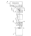
図12に概略的に図示したように、重合体材料は、押し出し成形ユニット1で加工処理される。押し出し成形ユニット1は、横方向の幅が、得ようとしており、かつ、最終消費者に提供しようとしている複数のデンタルテープの幅を合わせた幅に通常は相当する細長い切れという形態にプラスチックフィルム3を押し出し成形することを可能にするものである。
As schematically illustrated in FIG. 12, the polymer material is processed in an extrusion unit 1. The extruding unit 1 has a
図示の例において、プラスチックフィルム3は、冷却ロール4および誘導ロール5に通されて、エンボス加工ユニット20に送り込まれる。エンボス加工ユニット20は、図12に図示の実施形態では、硬化鋼を含む一対のエンボス加工ロール21、22で定められている。ただし、硬化鋼に限定するものではない。
In the illustrated example, the
プラスチックフィルム3は、一定の張力をかけて、好ましくは折れやねじれのない状態で、エンボス加工ユニット20に送り込まなければならない。
The
図1および図1Aに例示的に図示したデンタルテープ10では、外面11、12の一方だけがエンボス加工工程を受けている。このケースでは、上側のロール21のみに、プラスチックフィルム3の向かい合う外面に押しつけられる、好ましくは若干高い浮き彫り(不図示)となっている放射状要素が側面に設けられている。一方、他方のロール22は、滑らかな側面を有し、この側面は随意に加熱されるものであり、プラスチックフィルム3の外面はこの側面の上を通される。
In the
当然のことながら、デンタルテープ10の2つの、対向する外面にエンボスを設けることが望ましければ、エンボス加工ユニット20の両方のロール21、22は、その側面がプラスチックフィルム3の向かい合う面に作用して、それに所望のエンボス加工を施すように構成されなければならない。
Of course, if it is desired to provide embossing on the two opposite outer surfaces of the
図12に図示したように、既にエンボスが設けられたプラスチックフィルム3は、次に切断装置30に誘導される。切断装置は、任意の既知の構造をしていて、プラスチックフィルム3を長手方向に切断して複数のデンタルテープ10にするように設計されている。デンタルテープ10は、各々が所望の幅の単繊維11で定められ、対向する長手方向縁部がある。各デンタルテープ10は、次に、巻き取り装置40で個別に巻き取られる。巻き取り装置40には、エンボスを設けたプラスチックフィルム3から複数のデンタルテープ10を同時かつ個々に巻き取る能力がある。
As shown in FIG. 12, the
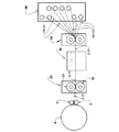
図13の線図は、デンタルフロスを得るための製法がコイル6から始まるという点でのみ図12の方法と異なる方法を図示しており、コイル6には、所望の重合体材料のフィルムであって、形成しようとしているデンタルフロスの厚みをしているが、得ようとしている複数のデンタルフロスの幅を合わせた幅にほぼ相当する幅を有するフィルムが入っている。この例において、デンタルフロスを得るための製法は、「オフライン」プロセスである。
The diagram of FIG. 13 illustrates a method that differs from the method of FIG. 12 only in that the process for obtaining dental floss begins with
図12Aおよび図13Aは、図12および図13に表したシステムおよび製法の変形例を図示しており、これによれば、既にエンボスが設けられたプラスチックフィルム3が、任意の既知の構造からなるコーティング塗布装置50へ、プラスチックフィルム3に少なくとも一つの結合剤を被覆するために誘導される。プラスチックフィルム3は、活性機能を有する少なくとも一つの添加剤を保持するための担体を定める。添加剤は、たとえば、香味剤、感覚知剤(sensate)、催唾液薬、着色剤、芳香剤、治療効果のある添加剤、研磨剤、鉱物回復剤(remineralizers)、殺菌剤等から選択されたものである。コーティング塗布装置50を通った後、プラスチックフィルム3は、切断装置30に誘導される。切断装置30では、プラスチックフィルム3が長手方向に切断され、所望の最終的な幅をした複数のデンタルテープ10になる。幅は、対向する長手方向縁部の間で画定される。
FIG. 12A and FIG. 13A illustrate a variation of the system and manufacturing process depicted in FIG. 12 and FIG. 13 according to which the
図13Bは、デンタルテープを得るための製法を実施することが可能な方法であって、選択された重合体材料から形成されており、かつ、得ようとしているデンタルテープの幅に相当する幅を呈するテープ3aが入ったコイル6aから始まる方法を図示している。既に最終的な幅に切断されており、本製法にコイル6aで供給されるテープ3aは、エンボス加工ユニット20へ、そして随意であるが、コーティング塗布装置50へ導かれ、その後、巻き取り装置40で巻き取られる。
FIG. 13B shows a method capable of carrying out a manufacturing method for obtaining a dental tape, which is formed of a selected polymer material and has a width corresponding to the width of the dental tape to be obtained. A method is illustrated starting with a
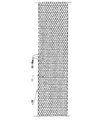
図1および図1Aは、単繊維デンタルテープ11の一方の外面12だけに加えられたエンボスパターンであり、単繊維11の外面12にあってデンタルテープ11の芯体14内へと突出している複数のくぼみを外面12に与えるエンボスパターンを例示している。
1 and FIG. 1A are emboss patterns applied only to one
図1、1Aおよび2〜11に図示の実施形態において、くぼみ15は、そのくぼみ15を加えた単繊維11の実質的に横幅全体にわたって存在している。しかし、当然のことながら、くぼみ15が単繊維11の幅を実質的に占有している状態でも、くぼみ15がそれぞれのデンタルテープ10の不連続な長手方向の範囲を占めることは可能であり、この場合、これらのテープ長手方向長さにおいてくぼみで占められていない部分があることになる。よって、くぼみ15は、くぼみをエンボス加工した単繊維デンタルテープ11の外面12における表面積の約5%から約95%に設けられる。
In the embodiment illustrated in FIGS. 1, 1A and 2-11, the
また、図1から図11においても認められるであろうが、平面図におけるくぼみ15の個々の面積は、テープの単位表面積当たりのくぼみの数と合わせると、くぼみの総面積と、そのくぼみが設けられているテープの面の部分の表面積との間の比が約5%から約95%になっている。
Also, as will be recognized in FIGS. 1 to 11, when the individual areas of the
これも認められたことであるが、くぼみ15は、そのくぼみが設けられたテープの表面に対する芯体内の深さが、上記テープ表面に横断するようにとったテープ3、3aの厚みの約0.1%から約95%、または、約0.1%から約50%に対応する。これらのくぼみ15は、単繊維11の表面積をかなり大きくすることを可能にし、このことは、以下に説明するように、デンタルテープ10に塗布するコーティングを固定する単繊維の能力を増大させる。
It is also recognized that the
図1〜11に例示的に図示したように、くぼみ15は、さまざまな形状を有することができる。図から分かるように、くぼみは、互いに間隔をおいて配置してもよいし、群を形成するように配置し、各群のくぼみが互いにつながっている状態にしてもよい。図1、2、3および5に図示したようないくつかの配列では、くぼみ15の群が互いにつながっている。
As illustrated by way of example in FIGS. 1 to 11, the
図1において、くぼみ15は、三角形配列に配置された小さくて直線的な溝部15aという形態をとっている。図2および3では、くぼみ15は、ここでも直線的な溝部15aという形態であるが、それぞれ、六角形および菱形の配列に配置されている。図4〜8は、くぼみ15の他の物理的配列を図示しており、この配列もまた、デンタルテープの掃除作用における把持機能および研磨機能を有する、デンタルテープの面の少なくとも一方の面からデンタルテープの芯体に設けられた溝部15aで画定されている。しかしながら、当然のことながら、他の多角形形状をこのようなくぼみの輪郭および配列に利用してもよく、また、重要なことは、くぼみを適切な寸法に形成して、デンタルテープ構造体の掃除特性を改善するだけでなく、香味剤、着色剤、芳香剤、治療効果のある添加剤、研磨剤、鉱物回復剤(remineralizing agents)、殺菌剤等の機能性添加剤を保持するための固定能力をも著しく増大させ、これら添加剤の単繊維構造体への付着を、好ましくは既知の結合剤を用いてテープの表面被覆という形態で行うこと、または、活性機能を有する上記添加剤をくぼみに直接塗布することでさえ可能にすることである。
In FIG. 1, the
図1、2、3、5および6は、また、直線的であったり、湾曲していたりする溝部15aという形態のくぼみが、デンタルテープ10の外面12の幅および長さ方向に互いに交差した領域を示す配列を図示している。
1, 2, 3, 5, and 6 are regions in which indentations in the form of linear or curved grooves 15 a intersect each other in the width and length directions of the
くぼみ15の形状および配列にもよるが、所望の程度の把持、掃除、柔軟性、および、表面被覆の固定を保証するために、くぼみ15の最小および最大の寸法を変えることができる。
Depending on the shape and arrangement of the
図1および3に示したように、くぼみ15は群を形成するように配列されており、その群の少なくとも一部のくぼみ15は直線的であり、外面12の対向する長手方向縁部と交差する方向に縦に並べられている。
As shown in FIGS. 1 and 3, the
図2、4および6に例示した構造では、各くぼみ群のくぼみ15が互いに角度をなしている。図5において、くぼみ15は、連続的で、直線的ではない溝部15aであって、互いに交差した領域がある溝部15aで画定されている。
In the structure illustrated in FIGS. 2, 4 and 6, the
図9および図10は、デンタルテープの長手方向軸に対して傾斜した方向に伸びた直線的で、平行な溝部15aによってくぼみ15が画定されている配列を図示している。図9において、各溝部15aには、間隔をおいて配置された複数のリブ部16が内部の深部に設けられている。リブ部16は、それぞれの溝部15aの長手方向軸を横断する方向に配列されている。同様に、図10の構造に図示した各溝部15aには、溝部15aの長手方向軸に対して傾いた平行リブ部16aが内部の深部に設けられている。
9 and 10 illustrate an arrangement in which the
図11は、くぼみ15が、間隔をおいて配置された半球形の凹部15bであって、それが設けられているデンタルテープ10の外面12の幅および長さの少なくとも一部に沿って設けられている凹部15bによって画定されている配列を図示している。
FIG. 11 shows that the
分かるであろうが、くぼみに与えられたデザインとは無関係に、くぼみは、好ましくは、デンタルテープの外面に対して凹部を設けるように構成しなければならず、また、もしあれば、デンタルテープ内部のさまざまな表面部分の間にも凹部を設けるように構成しなければならない。 As will be appreciated, regardless of the design given to the indentation, the indentation should preferably be configured to be recessed with respect to the outer surface of the dental tape, and if present, the dental tape. It must be configured to provide recesses between the various internal surface portions.
くぼみ15の寸法および構成は、結合剤および活性機能のある種々の添加剤を用いるかどうかにかかわらずデンタルテープに優れた把持特性および掃除特性を与えるだけでなく、使用者が取り扱う製品に高度の柔軟性をも与えるようにしなければならない。
The dimensions and configuration of the
単に非限定的な例として提供した図1から図11に示されているように、くぼみ15は、互いに平行であってもよいし、相互に交差する領域を有してもよく、くぼみが形成されている単繊維の外面に最も多様な図面(diverse drawings)を定めている。くぼみ15は、くぼみの各々が、テープ10を画定する単繊維11の幅全体を占めるように設けてもよいし、単繊維11の一部だけを占めるように設けてもよい。後者の場合、互いに交差するさまざまなくぼみ15を組み合わせることで、それぞれの単繊維11の幅全体に上記くぼみが設けられるようになる。
As shown in FIGS. 1 to 11 provided merely as a non-limiting example, the
上述した構造では、くぼみで定められた表面要素がデンタルテープにあり、この表面要素は、デンタルテープの掃除能力をより大きくするが、前述したようなさまざまな添加剤を適切に混ぜることができる担体を定める機能のある結合剤でテープの表面および外部を被覆することをも可能にする。本明細書で提案するデンタルテープの固定能力がより大きいので、このデンタルテープは、滑らかな単繊維テープに比べて著しく多量の結合剤を備えることができ、活性機能のある添加剤をデンタルテープに確実に凝集させ、結合剤に定められた担体との混合物におけるこれら活性添加剤の割合をずっと多くすることを可能にする。これにより、デンタルテープは、必要であれば、活性機能のある添加剤をより多く備えることができ、それでいて、上記デンタルテープで望まれている高い水準の柔軟性を損なわず、また、デンタルテープの使用中に、歯間空間に、より集中的に機能性添加剤を放出する能力は著しく高まる。 In the structure described above, the surface element defined by the depression is in the dental tape, this surface element increases the cleaning ability of the dental tape, but the carrier that can be properly mixed with various additives as described above It is also possible to coat the surface and the exterior of the tape with a binder that has the function of defining Due to the greater fixing capacity of the dental tape proposed here, this dental tape can have significantly more binder than a smooth monofilament tape and can add active functional additives to the dental tape. It ensures agglomeration and allows a much higher proportion of these active additives in the mixture with the carrier defined in the binder. This allows the dental tape to be provided with more active functional additives, if necessary, without compromising the high level of flexibility desired with the above-mentioned dental tape, During use, the ability to release functional additives more intensively into the interdental space is significantly enhanced.
くぼみおよび任意の突起部によりもたらされる大きな固定能力から得られた上述の利点によって、デンタルテープの結合剤は、柔軟性を損なうことなく、単繊維の質量の約0.1%から約40%とすることができる。 Due to the above-mentioned advantages gained from the large anchoring capacity provided by the indentations and optional protrusions, dental tape binders can be used from about 0.1% to about 40% of the single fiber mass without loss of flexibility. can do.
ここまで、円筒状の鋼鉄ロール21、22によるエンボス加工製法を説明したが、当然のことながら、単繊維11のエンボス加工は、上述した機械的手段とは異なる他の手段で行うこともできる。たとえば、後に単繊維11を形成するプラスチックフィルム3の表面のエンボス加工は、超音波によって、または、レーザによってさえ、これらの分野で既知の手法を用いて行うこともできる。
Up to this point, the embossing manufacturing method using the cylindrical steel rolls 21 and 22 has been described. However, as a matter of course, the embossing of the
本発明はまた、消費者に販売するデンタルテープに対応した幅を各々が有する、複数のテープに後で長手方向に分割される、押し出し成形された同じプラスチック単繊維フィルムから、上述したデンタルテープを形成する製法に関するものである。 The present invention also provides the above-described dental tape from the same extruded extruded plastic monofilament film, which is subsequently divided longitudinally into a plurality of tapes each having a width corresponding to the dental tape sold to the consumer. It relates to the manufacturing method to be formed.
本発明を実施する方法によれば、本製法は、プラスチックフィルム3の外面の範囲における少なくとも一部に、形成しようとするデンタルテープ10の断面の輪郭の少なくとも一部を画定する複数のくぼみ15を設けるために、本開示で先に定義したグループから選択されたポリマーから押し出し成形されたプラスチックフィルム3がエンボス加工工程を受けるという、基本的初期段階を含む。
According to the method of practicing the present invention, the manufacturing method includes a plurality of
既にエンボスが加工されたフィルムは、次に、各々、形成しようとするデンタルテープ10の幅に相当する幅を有する複数のデンタルテープ10に長手方向に分割される。
The embossed film is then divided in the longitudinal direction into a plurality of
既にエンボスが設けられたデンタルテープ10は、オプションとして、抗歯垢剤、殺菌剤、香味剤、感覚知剤(sensates)、催唾液剤、着色剤、芳香剤、治療効果のある添加剤、研磨剤、および、鉱物回復剤からなる群から選択された活性機能がある少なくとも一つの添加剤を、上述したくぼみ15に付着、固定させるために、その少なくとも一つの添加剤でコーティングされ、次に、図12および12Aに概略的に図示したように、得られたデンタルテープを巻き取る。
The
前述したように、図13および13Aは、デンタルテープ10を得るための製法の変形例を図示しており、この変形例は、図12および12Aに示されている製法とは、予め押し出し成形されていて、コイル6に保管されているプラスチックフィルム3から始まっている点においてのみ異なっている(オフライン製法)。
As described above, FIGS. 13 and 13A illustrate a modification of the manufacturing method for obtaining the
図13Bの例示では、この製法は、得ようとしているデンタルテープ10の幅に相当する幅の単繊維テープ3aから開始している。
In the illustration of FIG. 13B, this manufacturing method starts with a
以下の実施例は、本発明のある種の実施形態を例示するために提供するものであり、本発明の範囲を限定しようとするものではない。 The following examples are provided to illustrate certain embodiments of the invention and are not intended to limit the scope of the invention.
実施例1:デンタルテープ形成
表面にさまざまなくぼみのある一連の単繊維デンタルテープを以下に述べるように加工処理した。全てのテープで、使用したポリマーは、ポリテトラフルオロエチレン(PTFE)であった。PTFEは粉末として供給され、押し出し成形製法でテープに加工された。工程は以下の通りであった。
Example 1 Dental Tape Formation A series of single fiber dental tapes with various indentations on the surface were processed as described below. For all tapes, the polymer used was polytetrafluoroethylene (PTFE). PTFE was supplied as a powder and processed into a tape by an extrusion molding method. The process was as follows.
1)PTFEは、19℃、相対湿度(RH)40パーセントで保管した。
2)混合潤滑油および増量剤を加えてバッチを作った。
3)バッチは、押し出し成形前に、エージングのために約24時間保管した。
4)バッチは、垂直押し出し法でフラットダイを通して押し出し、リボンを形成した。
5)いったん押し出し成形を行ったら、そのリボンはカレンダーにかけ、乾燥させ、かつ、引き伸ばし、所望の密度および幾何学的特性を有するPTFEテープを得た。
1) PTFE was stored at 19 ° C. and relative humidity (RH) 40 percent.
2) A batch was made by adding mixed lubricant and extender.
3) The batch was stored for about 24 hours for aging before extrusion.
4) The batch was extruded through a flat die by the vertical extrusion method to form a ribbon.
5) Once extruded, the ribbon was calendered, dried and stretched to obtain a PTFE tape having the desired density and geometric properties.
PTFEリボンには、機械的なエンボス加工でエンボスを設けた。機械的エンボス加工は、一方が雄の突起部、他方が雌の凹部を備えている一対のロールで提供される、コールドニップまたはホットニップ(cold or hot nip)であってもよい。 The PTFE ribbon was embossed by mechanical embossing. Mechanical embossing may be a cold or hot nip, provided with a pair of rolls, one with male protrusions and the other with female recesses.
熱間機械加工の場合、ロールは個別に温度を制御しながら加熱された。温度範囲は、50℃から200℃まで変動してもよく、テープを作るポリマーによっては、より高くなることさえある。ロール間の間隙は、0.01mmからテープの厚さまで変動しうる。ロール間の圧力は、500から1500Mpaまで変動しうる。雄ロールまたは雌ロールは、鋼鉄またはゴムから作ることができる。鋼鉄から作った場合、硬度は30から60HRC(ロックウェル硬度Cスケール)となるであろうし、ゴムから作れば、ショアA硬度(shore A)が50から100となるであろう。 In the case of hot machining, the rolls were heated while individually controlling the temperature. The temperature range may vary from 50 ° C. to 200 ° C. and may even be higher depending on the polymer making the tape. The gap between the rolls can vary from 0.01 mm to the thickness of the tape. The pressure between the rolls can vary from 500 to 1500 MPa. The male or female roll can be made from steel or rubber. If made from steel, the hardness will be 30-60 HRC (Rockwell Hardness C scale), and if made from rubber, the Shore A hardness (shore A) will be 50-100.
冷間機械加工の場合、ロールの温度は制御されなかった。ロール間の間隙は、0.01mmからテープの厚さまで変動しうる。ロール間の圧力は、500から1500Mpaまで変動しうる。雄ロールまたは雌ロールは、鋼鉄またはゴムから作ることができる。鋼鉄から作った場合、硬度は、30から60HRCとなるであろうし、ゴムから作れば、ショアA硬度(shore A)が50から100となるであろう。 In the case of cold machining, the temperature of the roll was not controlled. The gap between the rolls can vary from 0.01 mm to the thickness of the tape. The pressure between the rolls can vary from 500 to 1500 MPa. The male or female roll can be made from steel or rubber. If made from steel, the hardness will be 30 to 60 HRC, and if made from rubber, the Shore A hardness (shore A) will be 50 to 100.
実施例2:デンタルテープの柔軟性
実施例1で作った単繊維デンタルテープの内のいくつかの柔軟性を以下の柔軟性試験法で測定した。なお、全てのサンプルは、同一の材料のロットから取得した。
Example 2: Flexibility of dental tape Some of the flexibility of the single fiber dental tape made in Example 1 was measured by the following flexibility test method. All samples were obtained from the same material lot.
最初に、長さが10センチメートルの試験片を3つ、所望のデンタルテープのサンプルが入ったディスペンサーから収集した。いずれの場合にも、デンタルテープディスペンサーの最初の50cmは廃棄し、同様に、試験片の間の50cmも廃棄した。次に、0.10グラムの重りを各試験片の両端に取り付けた。次に、各試験片を直径0.65ミリメートルの水平な金属製のピンに引っ掛け、各試験片のぶら下がっている両端が金属製のピンからちょうど同じ距離となるようにした。試験片は、予め設定した条件下で(22℃/50%RH)2時間そのままにし、順応させた。この時点で、各試験片のデジタル写真を撮った。各試験片のぶら下げた「足部」の間の距離(d)を、金属製ピンの下20mmにおける1mm間隔の3つの異なる点で、Leyca Qwin画像解析用ソフトウェアを用いて測定した。 Initially, three 10 cm long specimens were collected from a dispenser containing a sample of the desired dental tape. In all cases, the first 50 cm of the dental tape dispenser was discarded, as was the 50 cm between the test pieces. Next, a 0.10 gram weight was attached to each end of each specimen. Next, each test piece was hooked on a horizontal metal pin having a diameter of 0.65 mm so that both ends of the test piece were exactly the same distance from the metal pin. The specimen was allowed to acclimate for 2 hours under preset conditions (22 ° C./50% RH). At this point, a digital photograph of each specimen was taken. The distance (d) between the hanging “foot” of each specimen was measured using the Leyca Qwin image analysis software at three different points, 1 mm apart 20 mm below the metal pin.
試験を行った各試験片の端部間の距離(d)は、デンタルテープの柔軟性(または、撓みに対する抵抗)を評価するのに用いるパラメータである。試験片の端部間の距離が長いほど、試験片の抵抗が大きく、したがって、製品はより柔軟性に欠ける。 The distance (d) between the ends of each test piece tested is a parameter used to evaluate the flexibility (or resistance to deflection) of the dental tape. The longer the distance between the ends of the specimen, the greater the resistance of the specimen, and therefore the product is less flexible.
上述した柔軟性試験は、本発明のデンタルテープで全くエンボスがないもの(対照標準)と、添付図面の図2、3、9、10および11に例示したエンボスパターンを有するものに適用した。柔軟性の結果は、下記の表1に示した。

上記の表1から分かるように、本発明により設けられたエンボスは、デンタルテープの柔軟性の増大、つまり、エンボスなし対照標準に比べエンボス付きサンプルの柔軟性距離の著しい減少につながっている。「レザー(leather)」エンボスパターンを除き、全てのエンボスパターンは、エンボスなし対照標準に比べエンボス付きサンプルの柔軟性距離が統計的に著しく減少するという結果になった。 As can be seen from Table 1 above, the embossing provided by the present invention leads to an increase in the flexibility of the dental tape, i.e. a significant decrease in the flexibility distance of the embossed sample compared to the unembossed control. With the exception of the “leather” embossed pattern, all embossed patterns resulted in a statistically significant reduction in the flexibility distance of the embossed sample compared to the unembossed control.
実施例3:デンタルテープの摩擦
PTFE単繊維の小さい表面積、ならびに、低い表面の張力(surface tension)および/または低い摩擦係数は、PTFE単繊維をデンタルフロスとして用いたときの歯間領域におけるバイオフィルム除去に関し性能が悪いことの原因である。本発明のエンボス付きポリテトラフルオロエチレン(PTFE)テープをエンボスのない対照標準と比べるために、摩擦試験を行った。
Example 3: Friction of dental tape The small surface area of PTFE monofilament and the low surface tension and / or low coefficient of friction is a biofilm in the interdental region when PTFE monofilament is used as dental floss. This is a cause of poor performance in terms of removal. A friction test was performed to compare the embossed polytetrafluoroethylene (PTFE) tape of the present invention with an unembossed control.
試験方法は、CRE型検力計(Dynamometer type CRE)、商標INSTRON、モデル5869を用いて行った。モデル5869では、ディアボロ形状のピンがデンタルテープに対する摩擦点として作用するように利用されている。試験条件は、以下の通りである。
1.20±2℃およびRH65±4パーセント
2.固定グリップおよび第一摩擦ピンの間の初期距離:250mm
3.第一および第二摩擦点の配置は約45°
4.摩擦ピン間の距離:115mm
5.重量:50グラム
6.試験速度:300mm/分
7.変位(Displacement):180mm
8.サンプル長さ:650mm
9.各サンプルについて5つの試験片をテスト
The test method was performed using a CRE type dynamometer (CRE), trademark INSTRON, model 5869. In the model 5869, a diabolo-shaped pin is used to act as a friction point against the dental tape. The test conditions are as follows.
1. 20 ± 2 ° C. and RH 65 ± 4 percent Initial distance between fixed grip and first friction pin: 250mm
3. The arrangement of the first and second friction points is about 45 °
4). Distance between friction pins: 115mm
5. Weight: 50 grams Test speed: 300 mm /
8). Sample length: 650mm
9.
ロードセルで、二つのディアボロ形状ピンに対する各デンタルテープ表面の摩擦力を測定した。 Using a load cell, the frictional force of each dental tape surface against two Diaboro pins was measured.
上述した摩擦試験は、本発明のデンタルテープで全くエンボスがないもの(対照標準)と、添付図面の図2、3、9、10および11に例示したエンボスパターンを有するものに適用した。結果は、下記の表2に示した。
驚いたことに、エンボス加工の後、摩擦力は著しく増大し、この結果として、エンボスを付けた製品は、(エンボスのない)対照標準と比べた場合に、歯間空間におけるバイオフィルムおよび/または食べ物の残骸を機械的に除去することに関してよりよい性能を有することに加え、より握りやすい(滑りにくい)ことが期待される。 Surprisingly, after embossing, the frictional force increased significantly, and as a result, the embossed product was biofilm and / or in the interdental space when compared to a control (without embossing). In addition to having better performance with respect to mechanical removal of food debris, it is expected to be easier to grip (non-slip).
実施例4:(ISO 2 062/1993の試験方法に基づく)デンタルテープの機械特性
本発明のエンボス付きポリテトラフルオロエチレン(PTFE)テープの実施形態の引っ張り強さおよび伸びをエンボスなし対照標準と比較した。試験条件は以下の通りであった。
1.20±2℃およびRH65±4パーセント
2.ゲージ間距離:250mm
3.速度:250mm/分
4.サンプルの長さ:400mm
5.各サンプルについて5つの試験片をテストした
Example 4: Mechanical properties of dental tape (based on
1. 20 ± 2 ° C. and RH 65 ± 4 percent Distance between gauges: 250mm
3. Speed: 250 mm / min Sample length: 400mm
5. Five specimens were tested for each sample
上記の引っ張り強さおよび伸びの試験は、本発明のデンタルテープで全くエンボスがないもの(対照標準)と、添付図面の図2、3、9、10および11に例示したエンボスパターンを有するものに適用した。結果は、下記の表3に示した。
驚いたことに、エンボス加工は、本発明のテープの引っ張り強さを(エンボスのない)対照標準と比べて損なうことはなく、このため、本発明のテープをデンタルフロスとして用いるのに適したものにしている。 Surprisingly, the embossing does not impair the tensile strength of the tape of the present invention compared to the control standard (without embossing) and is therefore suitable for using the tape of the present invention as a dental floss. I have to.
エンボスを設けたポリテトラフルオロエチレン(PTFE)デンタルテープのコーティングを保持する能力を、テープ上のコーティングの安定性を判断するために測定した。 The ability to hold a coating of embossed polytetrafluoroethylene (PTFE) dental tape was measured to determine the stability of the coating on the tape.
25.4mm(1インチ)幅であり、密度が1.2〜1.7g/cm3、1000〜17000デニール、そして厚みが3.6×10−2〜6.1×10−2mm(1.4−2.4mils)であるPTFEシートは、2つの異なる強度で「ハニカム」パターン(図2を参照)を使用した。エンボスのないサンプルが対照標準として使用された。全てのサンプルは、Bostik Findley(ウィスコンシン、ウォーワトサ)製の接着剤H2669でロットAS6081405を21g/m2を目標としてコーティングし、さらに試験を行うまで取り扱っている間に接着剤が損なわれることを回避するためにシリコン処理紙で覆った。 It is 25.4 mm (1 inch) wide, has a density of 1.2 to 1.7 g / cm 3 , 1000 to 17000 denier, and a thickness of 3.6 × 10 −2 to 6.1 × 10 −2 mm (1.4 The PTFE sheet (−2.4 mils) used a “honeycomb” pattern (see FIG. 2) with two different strengths. An unembossed sample was used as a control. All samples are coated with adhesive H2669 from Bostik Findley (Wisconsin, Wisconsin) targeting lot AS6081405 to 21 g / m 2 to avoid damaging the adhesive during handling until further testing. In order to cover it with siliconized paper.
次に、サンプルの剥離力を以下の工程にしたがって試験した(n=10):
1.コーティングをした基材のサンプルを15cm切断する。
2.シリコン処理紙を除去する。
3.サンプルの重さを計る。
4.100%綿の布をサンプルの上に配置する。
5.コーティングした基材に布を押しつける。自動システムを用いて標準重量(2230グラム)をサンプルの長手方向に一定速度(305mm/分(12インチ/分))で加えた。加圧処置は一回だけ行った。
6.最終的なサンプル(PTFE−接着剤−布)を剥離装置に配置する。
7.布を完全にはぎ取るための力を測定する。
8.サンプルの重さを計る。
Next, the peel strength of the sample was tested according to the following steps (n = 10):
1. A sample of the coated substrate is cut 15 cm.
2. Remove the siliconized paper.
3. Weigh the sample.
4. Place a 100% cotton cloth over the sample.
5. Press the cloth against the coated substrate. A standard weight (2230 grams) was added at a constant rate (305 mm / min (12 inches / min)) along the length of the sample using an automated system. The pressure treatment was performed only once.
6). The final sample (PTFE-adhesive-cloth) is placed in the peeling device.
7). Measure the force to completely peel off the fabric.
8). Weigh the sample.
サンプルの平均的な剥離力および接着剤損失は以下の表4に示した。
表は、エンボスを設けたサンプルのどちらの剥離力も対照標準の剥離力よりも小さいことを示している。エンボス加工の結果生じたくぼみは、接着剤がテープの表面下に達することを可能にしている。よって、綿布を接着するために利用できる量は減少し、綿布との結合は弱くなった。表はまた、対照標準の接着剤損失が、エンボスを設けたフロスのいずれと比較した場合も、著しく大きいことを示している。 The table shows that the peel strength of either embossed sample is less than that of the control. The indentation resulting from the embossing allows the adhesive to reach below the surface of the tape. Thus, the amount available to bond the cotton fabric was reduced and the bond with the cotton fabric was weakened. The table also shows that the control adhesive loss is significantly greater when compared to any embossed floss.
本発明の特定の特徴は、単に便宜のために一つまたは複数の図面に示されているが、各特徴は本発明による他の特徴と組み合わせることができる。代替の実施形態は、当業者に認識されるであろうし、特許請求の範囲の範囲内に含まれることが意図されている。よって、上記の記載は、本発明の範囲を例示しているが限定はしていないと解釈すべきである。このような明らかな変更および改良は、全て、添付した請求項の特許範囲内である。 Although specific features of the invention are shown in one or more drawings for convenience only, each feature may be combined with other features in accordance with the invention. Alternative embodiments will be recognized by those skilled in the art and are intended to be included within the scope of the claims. Accordingly, the above description should not be construed as illustrating, but limiting, the scope of the invention. All such obvious changes and modifications are within the scope of the appended claims.
〔実施の態様〕
(1)単繊維デンタルテープにおいて、
第一の外面、および、前記第一の外面とは反対側の第二の外面を有する芯体、
を備えており、
前記単繊維デンタルテープが前記デンタルテープとして使用するのに適した厚みおよび幅を有し、
前記第一および第二の外面の少なくとも一方は、前記芯体内へと突き出す複数のくぼみを有し、前記複数のくぼみは、前記第一および第二の外面の前記少なくとも一方の全面積の約5%から約95%に設けられており、
前記くぼみは、前記複数のくぼみを備えた前記第一および第二の外面の前記少なくとも一方に関して、前記芯体内への深さを有し、その深さは、前記複数のくぼみを備えた前記第一および第二の外面の前記少なくとも一方に対して横断するようにとった前記芯体の厚みの約0.1%から約95%に相当する、デンタルテープ。
(2)実施態様1に記載のデンタルテープにおいて、
前記複数のくぼみは、前記デンタルテープの実質的に全幅にわたって設けられている、デンタルテープ。
(3)実施態様1に記載のデンタルテープにおいて、
前記複数のくぼみは、前記デンタルテープの不連続な長手方向の範囲を占めている、デンタルテープ。
Embodiment
(1) In single fiber dental tape,
A core having a first outer surface and a second outer surface opposite to the first outer surface;
With
The monofilament dental tape has a thickness and width suitable for use as the dental tape,
At least one of the first and second outer surfaces has a plurality of indentations protruding into the core, the plurality of indentations being about 5 of the total area of the at least one of the first and second outer surfaces. % To about 95%,
The indentation has a depth into the core with respect to the at least one of the first and second outer surfaces with the plurality of indentations, the depth being the first with the plurality of indentations. Dental tape corresponding to about 0.1% to about 95% of the thickness of the core taken across the at least one of the first and second outer surfaces.
(2) In the dental tape of embodiment 1,
The plurality of indentations are dental tape provided over substantially the entire width of the dental tape.
(3) In the dental tape according to embodiment 1,
The plurality of indentations occupy a discontinuous longitudinal range of the dental tape.
(4)実施態様1に記載のデンタルテープにおいて、
前記くぼみは、凹部で画定されており、
前記デンタルテープは、前記凹部に挿入された突出部をさらに備えている、デンタルテープ。
(5)実施態様1に記載のデンタルテープにおいて、
結合剤を含むコーティング、
をさらに備えている、デンタルテープ。
(6)実施態様5に記載のデンタルテープにおいて、
前記コーティングは、活性機能を有する添加剤を含んでいる、デンタルテープ。
(7)実施態様1に記載のデンタルテープにおいて、
前記くぼみは、多角形、直線、非直線、卵形、楕円形、および、円形からなる群から選択された形状である、デンタルテープ。
(8)実施態様1に記載のデンタルテープにおいて、
前記第一および第二の外面の各々は、前記複数のくぼみを備えている、デンタルテープ。
(9)実施態様8に記載のデンタルテープにおいて、
前記複数のくぼみが占めている前記第一および第二の外面の各々の表面積は、約5%から約95%である、デンタルテープ。
(4) In the dental tape according to embodiment 1,
The indentation is defined by a recess;
The dental tape is further provided with a protrusion inserted into the recess.
(5) In the dental tape according to embodiment 1,
A coating containing a binder,
Dental tape that is further equipped with.
(6) In the dental tape according to
The dental tape includes an additive having an active function.
(7) In the dental tape according to embodiment 1,
The indentation is a dental tape having a shape selected from the group consisting of a polygon, a straight line, a non-linear line, an oval shape, an oval shape, and a circular shape.
(8) In the dental tape according to embodiment 1,
Each of the first and second outer surfaces is a dental tape comprising the plurality of indentations.
(9) In the dental tape according to embodiment 8,
A dental tape wherein the surface area of each of the first and second outer surfaces occupied by the plurality of indentations is from about 5% to about 95%.
(10)実施態様9に記載のデンタルテープにおいて、
前記複数のくぼみは、前記デンタルテープの実質的に全幅にわたって設けられている、デンタルテープ。
(11)実施態様10に記載のデンタルテープにおいて、
前記複数のくぼみは、前記デンタルテープの不連続な長手方向の範囲を占めている、デンタルテープ。
(12)実施態様9に記載のデンタルテープにおいて、
前記くぼみは、多角形、直線、非直線、卵形、楕円形、および、円形からなる群から選択された形状である、デンタルテープ。
(13)実施態様9に記載のデンタルテープにおいて、
結合剤を含むコーティング、
をさらに備えている、デンタルテープ。
(14)実施態様13に記載のデンタルテープにおいて、
前記コーティングは、活性機能を有する添加剤を含む、デンタルテープ。
(15)実施態様1に記載のデンタルテープにおいて、
ポリオレフィン、ポリアミド、ポリエステル、および、フルオロポリマーからなる群から選択されたポリマー、
を備える、デンタルテープ。
(10) In the dental tape according to embodiment 9,
The plurality of indentations are dental tape provided over substantially the entire width of the dental tape.
(11) In the dental tape according to
The plurality of indentations occupy a discontinuous longitudinal range of the dental tape.
(12) In the dental tape according to embodiment 9,
The indentation is a dental tape having a shape selected from the group consisting of a polygon, a straight line, a non-linear line, an oval shape, an oval shape, and a circular shape.
(13) In the dental tape according to embodiment 9,
A coating containing a binder,
Dental tape that is further equipped with.
(14) In the dental tape according to
The coating is a dental tape containing an additive having an active function.
(15) In the dental tape according to embodiment 1,
A polymer selected from the group consisting of polyolefins, polyamides, polyesters, and fluoropolymers,
With dental tape.
Claims (15)
第一の外面、および、前記第一の外面とは反対側の第二の外面を有する芯体、
を備えており、
前記単繊維デンタルテープが前記デンタルテープとして使用するのに適した厚みおよび幅を有し、
前記第一および第二の外面の少なくとも一方は、前記芯体内へと突き出す複数のくぼみを有し、前記複数のくぼみは、前記第一および第二の外面の前記少なくとも一方の全面積の約5%から約95%に設けられており、
前記くぼみは、前記複数のくぼみを備えた前記第一および第二の外面の前記少なくとも一方に関して、前記芯体内への深さを有し、その深さは、前記複数のくぼみを備えた前記第一および第二の外面の前記少なくとも一方に対して横断するようにとった前記芯体の厚みの約0.1%から約95%に相当する、デンタルテープ。 In single fiber dental tape,
A core having a first outer surface and a second outer surface opposite to the first outer surface;
With
The monofilament dental tape has a thickness and width suitable for use as the dental tape,
At least one of the first and second outer surfaces has a plurality of indentations protruding into the core, the plurality of indentations being about 5 of the total area of the at least one of the first and second outer surfaces. % To about 95%,
The indentation has a depth into the core with respect to the at least one of the first and second outer surfaces with the plurality of indentations, the depth being the first with the plurality of indentations. Dental tape corresponding to about 0.1% to about 95% of the thickness of the core taken across the at least one of the first and second outer surfaces.
前記複数のくぼみは、前記デンタルテープの実質的に全幅にわたって設けられている、デンタルテープ。 The dental tape according to claim 1,
The plurality of indentations are dental tape provided over substantially the entire width of the dental tape.
前記複数のくぼみは、前記デンタルテープの不連続な長手方向の範囲を占めている、デンタルテープ。 The dental tape according to claim 1,
The plurality of indentations occupy a discontinuous longitudinal range of the dental tape.
前記くぼみは、凹部で画定されており、
前記デンタルテープは、前記凹部に挿入された突出部をさらに備えている、デンタルテープ。 The dental tape according to claim 1,
The indentation is defined by a recess;
The dental tape is further provided with a protrusion inserted into the recess.
結合剤を含むコーティング、
をさらに備えている、デンタルテープ。 The dental tape according to claim 1,
A coating containing a binder,
Dental tape that is further equipped with.
前記コーティングは、活性機能を有する添加剤を含んでいる、デンタルテープ。 The dental tape according to claim 5,
The dental tape includes an additive having an active function.
前記くぼみは、多角形、直線、非直線、卵形、楕円形、および、円形からなる群から選択された形状である、デンタルテープ。 The dental tape according to claim 1,
The indentation is a dental tape having a shape selected from the group consisting of a polygon, a straight line, a non-linear line, an oval shape, an oval shape, and a circular shape.
前記第一および第二の外面の各々は、前記複数のくぼみを備えている、デンタルテープ。 The dental tape according to claim 1,
Each of the first and second outer surfaces is a dental tape comprising the plurality of indentations.
前記複数のくぼみが占めている前記第一および第二の外面の各々の表面積は、約5%から約95%である、デンタルテープ。 The dental tape according to claim 8,
A dental tape wherein the surface area of each of the first and second outer surfaces occupied by the plurality of indentations is from about 5% to about 95%.
前記複数のくぼみは、前記デンタルテープの実質的に全幅にわたって設けられている、デンタルテープ。 The dental tape according to claim 9,
The plurality of indentations are dental tape provided over substantially the entire width of the dental tape.
前記複数のくぼみは、前記デンタルテープの不連続な長手方向の範囲を占めている、デンタルテープ。 The dental tape according to claim 10,
The plurality of indentations occupy a discontinuous longitudinal range of the dental tape.
前記くぼみは、多角形、直線、非直線、卵形、楕円形、および、円形からなる群から選択された形状である、デンタルテープ。 The dental tape according to claim 9,
The indentation is a dental tape having a shape selected from the group consisting of a polygon, a straight line, a non-linear line, an oval shape, an oval shape, and a circular shape.
結合剤を含むコーティング、
をさらに備えている、デンタルテープ。 The dental tape according to claim 9,
A coating containing a binder,
Dental tape that is further equipped with.
前記コーティングは、活性機能を有する添加剤を含む、デンタルテープ。 The dental tape of claim 13,
The coating is a dental tape containing an additive having an active function.
ポリオレフィン、ポリアミド、ポリエステル、および、フルオロポリマーからなる群から選択されたポリマー、
を備える、デンタルテープ。 The dental tape according to claim 1,
A polymer selected from the group consisting of polyolefins, polyamides, polyesters, and fluoropolymers,
With dental tape.
Applications Claiming Priority (2)
| Application Number | Priority Date | Filing Date | Title |
|---|---|---|---|
| US89602907P | 2007-03-21 | 2007-03-21 | |
| US12/026,839 US7854235B2 (en) | 2007-03-21 | 2008-02-06 | Dental tape and process for obtaining a dental tape |
Publications (2)
| Publication Number | Publication Date |
|---|---|
| JP2008264515A true JP2008264515A (en) | 2008-11-06 |
| JP2008264515A5 JP2008264515A5 (en) | 2011-02-17 |
Family
ID=39627782
Family Applications (1)
| Application Number | Title | Priority Date | Filing Date |
|---|---|---|---|
| JP2008071048A Pending JP2008264515A (en) | 2007-03-21 | 2008-03-19 | Dental tape and process for obtaining dental tape |
Country Status (6)
| Country | Link |
|---|---|
| US (1) | US7854235B2 (en) |
| EP (1) | EP1972305A1 (en) |
| JP (1) | JP2008264515A (en) |
| AU (1) | AU2008201348A1 (en) |
| BR (1) | BRPI0800649A (en) |
| RU (1) | RU2454969C2 (en) |
Cited By (2)
| Publication number | Priority date | Publication date | Assignee | Title |
|---|---|---|---|---|
| JP2011245310A (en) * | 2010-05-28 | 2011-12-08 | Mcneil Ppc Inc | Apparatus for manufacturing single-use dental floss holder |
| JP7367071B2 (en) | 2019-06-12 | 2023-10-23 | ダブリュ.エル.ゴア アンド アソシエイツ,インコーポレイティド | dental floss dispenser |
Families Citing this family (10)
| Publication number | Priority date | Publication date | Assignee | Title |
|---|---|---|---|---|
| US20090317264A1 (en) * | 2008-06-18 | 2009-12-24 | Schlumberger Technology Corporation | Esp motor windings for high temperature environments |
| WO2010014623A1 (en) * | 2008-07-29 | 2010-02-04 | Sunstar Americas, Inc. | Interdental cleaners and methods for making same |
| ES2373204T3 (en) | 2008-07-31 | 2012-02-01 | Mcneil-Ppc, Inc. | APPARATUS AND DENTAL TAPE COATING PROCEDURE. |
| US20100028527A1 (en) | 2008-07-31 | 2010-02-04 | Harold Ochs | Process for Coating Dental Tape |
| US8316865B2 (en) | 2008-07-31 | 2012-11-27 | Mcneil-Ppc, Inc. | Process for winding dental tape |
| US8439049B2 (en) * | 2009-06-01 | 2013-05-14 | Zoya Lavrova | Braided dental floss |
| CA2789029C (en) * | 2010-02-08 | 2016-04-05 | The Procter & Gamble Company | Reduced variability coated floss |
| WO2012054800A1 (en) * | 2010-10-21 | 2012-04-26 | Diedwardo William A | Dental protective device and method of use |
| US20120234344A1 (en) * | 2011-03-17 | 2012-09-20 | Shih-Ling Hsu | Hair Elastic |
| US10058402B2 (en) * | 2016-04-18 | 2018-08-28 | Jeff Rickabaugh | Colored dental floss and a method for using colored dental floss |
Citations (5)
| Publication number | Priority date | Publication date | Assignee | Title |
|---|---|---|---|---|
| JPH0467416U (en) * | 1990-10-18 | 1992-06-15 | ||
| JPH10506337A (en) * | 1994-10-03 | 1998-06-23 | ウェストン プロダクツ リミテッド | Method and apparatus for forming expanded PTEE material, and PTFE material, especially dental floss |
| JPH11155887A (en) * | 1997-06-25 | 1999-06-15 | Mcneil Ppc Inc | Dental floss |
| JP2005052650A (en) * | 2003-08-05 | 2005-03-03 | Peri-Dent Ltd | Coated dental floss or tape |
| US20060237028A1 (en) * | 2005-04-21 | 2006-10-26 | Hamidy Nasser W | Dental floss |
Family Cites Families (44)
| Publication number | Priority date | Publication date | Assignee | Title |
|---|---|---|---|---|
| US4450849A (en) * | 1982-09-27 | 1984-05-29 | Cerceo Chris A | Dental physio-tape |
| US4646766A (en) * | 1982-10-01 | 1987-03-03 | Johnson & Johnson | Dental tape |
| US4776358A (en) * | 1986-09-23 | 1988-10-11 | Leonard Lorch | Floss employing microporous tapes sandwiching paste dentifrice |
| US4836226A (en) * | 1987-11-20 | 1989-06-06 | Wolak Ronald G | Endless article for cleaning teeth |
| US5209251A (en) * | 1988-03-29 | 1993-05-11 | Colgate-Palmolive Company | Dental floss |
| GB8819873D0 (en) * | 1988-08-22 | 1988-09-21 | Westone Prod Ltd | Dental floss & tape |
| US4941487A (en) * | 1989-07-11 | 1990-07-17 | Vanbeneden Floyd V | Fluoridated dental floss |
| US4998978A (en) * | 1990-01-10 | 1991-03-12 | Varum Shirley B | Tooth cleaning strip |
| GB9003292D0 (en) * | 1990-02-14 | 1990-04-11 | Lisney Kevin P | Dispensing mechanism |
| GB2250817A (en) * | 1990-12-12 | 1992-06-17 | Naresh Gathani | Dental caries diagnostic floss. |
| US5226435A (en) * | 1991-08-01 | 1993-07-13 | Gillette Canada Inc. | Flavored dental floss and method |
| US5293886A (en) * | 1993-02-18 | 1994-03-15 | Henry Czapor | Dental strip |
| AU694983B2 (en) * | 1994-06-06 | 1998-08-06 | Johnson & Johnson Consumer Companies, Inc. | Novel compositions for dental floss |
| US5518012A (en) * | 1994-06-15 | 1996-05-21 | W. L. Gore & Associates, Inc. | Expanded PTFE floss material and method of making same |
| US5588452A (en) * | 1995-05-10 | 1996-12-31 | Peck; Granger | Tooth cleansing and flossing implement and method |
| US5875797A (en) * | 1995-06-06 | 1999-03-02 | Gillette Canada Inc. | Dental floss |
| US6371133B1 (en) * | 1996-05-01 | 2002-04-16 | Loops, L.L.C. | Variable-guage tooth-flossing loops |
| US5865197A (en) * | 1996-05-20 | 1999-02-02 | Anchor Advanced Products, Inc. | Monofilament nylon dental floss |
| US6018840A (en) | 1998-03-09 | 2000-02-01 | Gillette Canada Inc. | Notched dental hygiene article |
| US6003525A (en) * | 1998-03-14 | 1999-12-21 | Katz; Harry S. | Elastomer floss and related flossing devices |
| US5967154A (en) * | 1998-05-04 | 1999-10-19 | Vision International Production, Inc. | Dental hygiene filament |
| US6340027B1 (en) * | 1998-08-17 | 2002-01-22 | Athena Nordic Ab | Extensible polishing mono-filament dental floss |
| DE19908238A1 (en) | 1999-02-25 | 2000-08-31 | Coronet Werke Gmbh | Cleaning element in particular for cleaning teeth and method for its production |
| CA2372293C (en) * | 1999-04-29 | 2013-04-09 | Neks Recherche & Developpement Inc. | Interproximal tooth coating applicator |
| US6016816A (en) * | 1999-07-16 | 2000-01-25 | Seaway Yarns Limited | Multi-colored dental floss and method of making |
| JP2001079022A (en) * | 1999-09-16 | 2001-03-27 | Gc Corp | Portable type small light for dental treatment at patient's house |
| WO2002015815A1 (en) * | 2000-08-23 | 2002-02-28 | Hill Ira D | Monofilament dental tapes with substantive coatings |
| US6604534B2 (en) * | 2000-08-23 | 2003-08-12 | International Tape Partners, Llc | Physical improvements in coated monofilament dental tapes |
| US20020104548A1 (en) * | 2000-12-01 | 2002-08-08 | Vipul Bhupendra Dave | Monofilament tape |
| US6453912B1 (en) * | 2000-12-07 | 2002-09-24 | Steven M. Antler | Dental floss with abrasives |
| US6536448B2 (en) * | 2000-12-29 | 2003-03-25 | Kimberly-Clark Worldwide, Inc. | Hemostat coated dental floss and hemostat coated dental tape |
| US6609527B2 (en) * | 2001-01-22 | 2003-08-26 | International Tape Partners, Llc | Non-crystalline saliva-soluble coatings for elastomeric monofilament dental tapes |
| EP1360133A4 (en) * | 2001-01-22 | 2007-05-23 | Tape Partners Ll International | Coated monofilament tape bobbins and methods for winding |
| US6591844B2 (en) * | 2001-01-22 | 2003-07-15 | Peri-Deat Limited | Elastomeric monofilament dental tapes |
| RU2269973C2 (en) * | 2001-08-17 | 2006-02-20 | СмитКлайн Бичем пи.эл.си. | Strap for delivering matter intended for mouth care |
| US6575176B1 (en) * | 2001-08-23 | 2003-06-10 | International Tape Partners, Llc | Monofilament dental tapes with soft abrasive coatings |
| US7017591B2 (en) * | 2001-08-23 | 2006-03-28 | International Tape Partners Llc | Particulate coated monofilament devices |
| US20030041873A1 (en) * | 2001-08-28 | 2003-03-06 | Dana Contratto | Dental strip and method of use thereof |
| US20060243297A1 (en) * | 2005-04-29 | 2006-11-02 | Brown Dale G | Coated monofilament oriented HDPE dental tapes |
| ATE320203T1 (en) * | 2002-04-24 | 2006-04-15 | Skg Italia S P A | TOOTH CLEANING DEVICE |
| US7055530B2 (en) * | 2003-02-25 | 2006-06-06 | Mardelle M. LaMoure | Dental cleaning strip |
| US7281541B2 (en) * | 2004-06-16 | 2007-10-16 | Lorch Leonard G | Dental floss |
| US20060016457A1 (en) * | 2004-07-23 | 2006-01-26 | Hoffman William A Iii | Dental tape |
| US20090120455A1 (en) * | 2007-11-08 | 2009-05-14 | Ochs Harold D | Multi-Ribbed Dental Tape |
-
2008
- 2008-02-06 US US12/026,839 patent/US7854235B2/en active Active
- 2008-03-19 JP JP2008071048A patent/JP2008264515A/en active Pending
- 2008-03-20 AU AU2008201348A patent/AU2008201348A1/en not_active Abandoned
- 2008-03-20 RU RU2008110780/14A patent/RU2454969C2/en not_active IP Right Cessation
- 2008-03-20 EP EP08250987A patent/EP1972305A1/en not_active Withdrawn
- 2008-03-20 BR BRPI0800649-0A patent/BRPI0800649A/en not_active Application Discontinuation
Patent Citations (5)
| Publication number | Priority date | Publication date | Assignee | Title |
|---|---|---|---|---|
| JPH0467416U (en) * | 1990-10-18 | 1992-06-15 | ||
| JPH10506337A (en) * | 1994-10-03 | 1998-06-23 | ウェストン プロダクツ リミテッド | Method and apparatus for forming expanded PTEE material, and PTFE material, especially dental floss |
| JPH11155887A (en) * | 1997-06-25 | 1999-06-15 | Mcneil Ppc Inc | Dental floss |
| JP2005052650A (en) * | 2003-08-05 | 2005-03-03 | Peri-Dent Ltd | Coated dental floss or tape |
| US20060237028A1 (en) * | 2005-04-21 | 2006-10-26 | Hamidy Nasser W | Dental floss |
Cited By (2)
| Publication number | Priority date | Publication date | Assignee | Title |
|---|---|---|---|---|
| JP2011245310A (en) * | 2010-05-28 | 2011-12-08 | Mcneil Ppc Inc | Apparatus for manufacturing single-use dental floss holder |
| JP7367071B2 (en) | 2019-06-12 | 2023-10-23 | ダブリュ.エル.ゴア アンド アソシエイツ,インコーポレイティド | dental floss dispenser |
Also Published As
| Publication number | Publication date |
|---|---|
| RU2454969C2 (en) | 2012-07-10 |
| AU2008201348A1 (en) | 2008-10-09 |
| US7854235B2 (en) | 2010-12-21 |
| BRPI0800649A (en) | 2008-11-04 |
| RU2008110780A (en) | 2009-09-27 |
| EP1972305A1 (en) | 2008-09-24 |
| US20080230087A1 (en) | 2008-09-25 |
Similar Documents
| Publication | Publication Date | Title |
|---|---|---|
| JP2008264515A (en) | Dental tape and process for obtaining dental tape | |
| JP3609419B2 (en) | Improved expanded PTFE floss material and method for producing the same | |
| KR100874282B1 (en) | Tuft formed laminate web | |
| US5765576A (en) | Dental floss article and method of making same | |
| US20060243297A1 (en) | Coated monofilament oriented HDPE dental tapes | |
| JP4712976B2 (en) | Dental floss holder | |
| AU770535B2 (en) | Improved dental floss having low density and method of making same | |
| AU708978B2 (en) | Dental floss | |
| US5692530A (en) | Braided dental floss | |
| RU2465863C2 (en) | Dental tape with number of ribs | |
| KR100451331B1 (en) | Improved dental floss having low density and method of making same | |
| EP0980678B1 (en) | Dental floss having improved fray and shred resistance | |
| EP1474092A1 (en) | Micromesh interproximal devices | |
| US6506327B2 (en) | Process of making monofilaments | |
| RU2197572C2 (en) | Monofilament, method for manufacture of bristles and interdental cleaning members, and bristles and interdental cleaning members manufactured from such monofilaments | |
| GB2278283A (en) | Dental floss | |
| JP2009142481A (en) | Bristle material for cosmetic brush and cosmetic brush | |
| JP6866851B2 (en) | Laminated non-woven fabric | |
| CA2625358A1 (en) | Dental tape and process for obtaining a dental tape | |
| US6238605B1 (en) | Low-fibrillation moulded bodies | |
| AU2004202082B2 (en) | Improved dental floss | |
| MXPA00004302A (en) | Monofil for and for producing bristles or interdental cleaning elements, bristle products with bristles of this type and interdental cleaning elements | |
| JP2005080958A (en) | Toothbrush |
Legal Events
| Date | Code | Title | Description |
|---|---|---|---|
| RD04 | Notification of resignation of power of attorney |
Free format text: JAPANESE INTERMEDIATE CODE: A7424 Effective date: 20100708 |
|
| A521 | Written amendment |
Free format text: JAPANESE INTERMEDIATE CODE: A523 Effective date: 20101222 |
|
| A621 | Written request for application examination |
Free format text: JAPANESE INTERMEDIATE CODE: A621 Effective date: 20101222 |
|
| RD04 | Notification of resignation of power of attorney |
Free format text: JAPANESE INTERMEDIATE CODE: A7424 Effective date: 20111125 |
|
| A131 | Notification of reasons for refusal |
Free format text: JAPANESE INTERMEDIATE CODE: A131 Effective date: 20120828 |
|
| A521 | Written amendment |
Free format text: JAPANESE INTERMEDIATE CODE: A523 Effective date: 20121115 |
|
| A02 | Decision of refusal |
Free format text: JAPANESE INTERMEDIATE CODE: A02 Effective date: 20130205 |
|
| A521 | Written amendment |
Free format text: JAPANESE INTERMEDIATE CODE: A523 Effective date: 20130422 |
|
| A911 | Transfer to examiner for re-examination before appeal (zenchi) |
Free format text: JAPANESE INTERMEDIATE CODE: A911 Effective date: 20130430 |
|
| A912 | Re-examination (zenchi) completed and case transferred to appeal board |
Free format text: JAPANESE INTERMEDIATE CODE: A912 Effective date: 20130621 |