JP2008262839A - Harness connecting member - Google Patents
Harness connecting member Download PDFInfo
- Publication number
- JP2008262839A JP2008262839A JP2007105455A JP2007105455A JP2008262839A JP 2008262839 A JP2008262839 A JP 2008262839A JP 2007105455 A JP2007105455 A JP 2007105455A JP 2007105455 A JP2007105455 A JP 2007105455A JP 2008262839 A JP2008262839 A JP 2008262839A
- Authority
- JP
- Japan
- Prior art keywords
- insertion hole
- terminal
- holding body
- connecting member
- pin
- Prior art date
- Legal status (The legal status is an assumption and is not a legal conclusion. Google has not performed a legal analysis and makes no representation as to the accuracy of the status listed.)
- Pending
Links
Images


Abstract
Description
本発明は、例えば自動車のハーネス回路において使用するハーネス接続部材に関するものである。 The present invention relates to a harness connecting member used in a harness circuit of an automobile, for example.
ハーネス回路においては、幹線から複数の枝線を分岐する必要が屡々あり、従来では、各種の方法で接続を行っている。そのために従来では、幹線の一部の被覆を剥ぎ取り、露出した導体に枝線を圧着加工し分岐するスプライスジョイント方式と、幹線の端末部に回路分岐用コネクタを配し、幹線、枝線共に汎用コネクタ及び圧着端子を使用して分岐加工する例えば特許文献1に記載のジョイントコネクタ方式との2通りの方式が多く用いられている。
In a harness circuit, it is often necessary to branch a plurality of branch lines from a trunk line, and conventionally, connection is performed by various methods. Therefore, conventionally, a part of the trunk line is stripped, a splice joint method that branches by crimping the branch line to the exposed conductor, and a circuit branch connector is arranged at the terminal part of the trunk line. For example, two types of methods such as a joint connector method described in
前者のスプライスジョイント方式では、電線を1〜3本毎に圧着加工しなければならず、それらの加工後の状態では作業性が非常に悪いという問題があり、また製造ライン上で圧着加工することが困難なので、ライン生産には不向きである。 In the former splice joint method, one to three electric wires must be crimped, and there is a problem that workability is very poor in the state after the machining, and crimping is performed on the production line. Is difficult for line production.
そこで、このスプライスジョイント方式の問題点を解決するものとして、後者のジョイントコネクタが開発されている。このジョイントコネクタ方式では、ハーネス製造ライン上でのジョイント加工が可能となるため、スプライスジョイント方式と比較して生産効率が向上し、ハーネス回路の修正にも対応可能である。しかし、コネクタ及び嵌合する相手側汎用コネクタ、バスバー、接続端子などの部品点数が多くなることから、ハーネス回路の組立には時間を要するのが実状である。 Therefore, the latter joint connector has been developed as a solution to the problems of the splice joint method. This joint connector method enables joint processing on the harness production line, so that the production efficiency is improved as compared with the splice joint method, and it is possible to cope with the modification of the harness circuit. However, since the number of components such as connectors and mating general-purpose connectors, bus bars, connection terminals, and the like increases, it takes a long time to assemble the harness circuit.
特に、特許文献1に開示されているジョイントコネクタ方式においても、省スペース化、更なる作業性の向上、構造の簡素化、電流容量の増大など、解決しなければならない課題が多々ある。
In particular, the joint connector system disclosed in
本出願人は特願2005−312774号において、合成樹脂から成る柱状の保持体を用いたハーネス接続部材を提案している。しかし、上述の保持体は内部構造が複雑なため、金型が高価となり、製造がなかなか困難であるという問題がある。 In Japanese Patent Application No. 2005-31774, the present applicant has proposed a harness connecting member using a columnar holding body made of synthetic resin. However, since the above-mentioned holding body has a complicated internal structure, there is a problem that the mold is expensive and it is difficult to manufacture.
本発明の目的は、保持体を分割構造とすることにより、金型構造を簡素化し、安価に製造し得るハーネス接続部材を提供することにある。 An object of the present invention is to provide a harness connecting member that can be manufactured at a low cost by simplifying the mold structure by using a split structure for the holding body.
また、本発明の他の目的は、分割構造の保持体が分離し難いように保持体の周囲をカバー部材で覆うハーネス接続部材を提供することにある。 Another object of the present invention is to provide a harness connecting member that covers the periphery of the holding body with a cover member so that the divided structure holding body is difficult to separate.
上述の目的を達成するための本発明に係るハーネス接続部材の技術的特徴は、中心にピン挿入孔を有し、外側から内部に向けて複数の端子挿入孔を有し、内部において前記ピン挿入孔と連通する合成樹脂製の略円柱状の保持体を備え、該保持体は長手方向に複数個に分割した分割部材を組合わせたことにある。 Technical features of the harness connecting member according to the present invention for achieving the above-described object include a pin insertion hole at the center, a plurality of terminal insertion holes from the outside toward the inside, and the pin insertion inside A substantially cylindrical holder made of synthetic resin that communicates with the hole is provided, and the holder is formed by combining a plurality of divided members in the longitudinal direction.
また、本発明に係るハーネス接続部材の技術的特徴は、中心にピン挿入孔を有し、外側から内部に向けて複数の端子挿入孔を有し、内部において前記ピン挿入孔と連通する合成樹脂製の略円柱状の保持体と、該保持体の外側から覆い、割りスリットを有する円筒状のカバー部材とから成るハーネス接続部材であって、前記保持体は長手方向に複数個に分割した分割部材を組合わせたことにある。 Further, the technical feature of the harness connecting member according to the present invention is a synthetic resin having a pin insertion hole in the center, a plurality of terminal insertion holes from the outside to the inside, and communicating with the pin insertion hole inside A harness connecting member comprising a substantially cylindrical holding body made of a cylinder and a cylindrical cover member that covers from the outside of the holding body and has a split slit, wherein the holding body is divided into a plurality of parts in the longitudinal direction. It is in combining the members.
本発明に係るハーネス接続部材によれば、保持体を複数個に分割して組立てるので、金型が簡略化される。 According to the harness connecting member according to the present invention, the holding body is divided into a plurality of parts and assembled, so that the mold is simplified.
また、本発明に係るハーネス接続部材によれば、2つ割りの保持体をカバー部材により覆うことにより使用中の保持体の解体を防止し、また保持体の周囲の電気部材の絶縁を行うことができる。 Further, according to the harness connecting member according to the present invention, the split holding body is covered with the cover member to prevent the holding body in use from being disassembled, and the electrical members around the holding body are insulated. Can do.
本発明を図示の実施例に基づいて詳細に説明する。
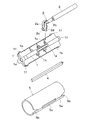
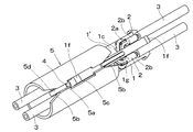
本実施例のハーネス接続部材は、主として図1に示すピン挿入孔1a、長溝1b、端子挿入孔1cを有する合成樹脂材から成る2つ割りの保持体1、1’と、保持体1、1’の端子挿入孔1cに挿入する接続部2a、電線3の芯線を接続した圧着部2bを有する複数個の電気端子2と、電気端子2同士を接続するためのピン端子4と、保持体1、1’に周設するカバー部材5とから構成されている。
The present invention will be described in detail based on the embodiments shown in the drawings.
The harness connecting member of the present embodiment is divided into two
保持体1、1’は図2に示すように長手方向に沿って同形状に2つ割りされた部材から成り、これらの合わせ目に沿って長手方向に鳩尾条1d、鳩尾溝1eが形成され、両者を互いに摺動させて一体化できるようにされている。2つ割り部材を合わせた保持体1、1’は略円柱体であり、保持体1、1’の中心軸を貫通しピン端子4を挿入するためのピン挿入孔1aが設けられ、保持体1、1’の表面に長手方向に沿って例えば計4個の断面略半円形の長溝1bが形成されている。
As shown in FIG. 2, the
なお、図示は省略しているが、保持体1、1’に形成される長溝1bは、上下又は左右対称に計2本形成したものであってもよい。更には、長溝1bを形成しない場合もある。
In addition, although illustration is abbreviate | omitted, the two
更に、長溝1bの底部には、各長溝1bごとに単数又は複数個の端子挿入孔1cが形成され、保持体1、1’の内部において中心のピン挿入孔1aと連通するようにされ、各端子挿入孔1cは電気端子2の接続部2aが挿入し得るように形成されている。
Further, at the bottom of the
保持体1、1’の両端外面の長溝1bを除く部分に、カバー部材5の端部を係止するための突環部1fが環状に形成され、更にそれぞれの長溝1b間の突部の一部には長手方向に沿って凸条部1gが設けられている。そして、突環部1fの内端側は壁部とされ、外端側は傾斜面とされている。なお、この突環部1fは円環状でなくとも、保持体1、1’の端部の適宜の個所に形成するようにしてもよい。
A protruding
電気端子2は1枚の導電金属板を打ち抜いて形成されており、後端の圧着部2bに対して内側に折り曲げられた前端の接続部2aには、円筒状に絞り加工された筒状接点2cが設けられている。
The
ピン端子4は図3の断面図に示すように、導電金属板を四角状に屈曲して複数層に形成すると、十分に補強され好適に使用できる。なお、金属棒を加工して用いてもよいし、その断面形状は丸型であってもよい。
As shown in the cross-sectional view of FIG. 3, the
カバー部材5は2つ割りの保持体1、1’が解体し難いように覆うと共に、保持体1、1’の周囲に配置された電気端子2の絶縁を兼ねて用いられる。カバー部材5は硬質合成樹脂から成る円筒体とされ、その内径は挿着すべき保持体1、1’の外径とほぼ同等か稍々小さくされている。カバー部材5の長手方向に割りスリット5aが形成され、割りスリット5aを拡開することができるようになっている。また、割りスリット5aの両端には切込み5bが設けられている。更に、割りスリット5aの中間には保持体1の凸条部1gに嵌合する凹形部5cが設けられている。更に、割りスリット5aの反対側には、保持体1’の他方の凸条部1gが嵌合するスリット部5dが形成されている。
The
組立に際しては、図4に示すように2つ割り部材を合体した保持体1、1’の端子挿入孔1cに、図1の矢印で示すように電線3を接続した電気端子2の接続部2aを挿入し、長溝1bに沿って電線3を装着する。接続部2aの縁部はピン挿入孔1aの径とほぼ一致しているので、図5に示すように接続部2aはピン挿入孔1a内において安定して装着され、筒状接点2cの中心はピン挿入孔1aの中心と一致する。なお、このとき端子挿入孔1cに設けた図示しない係止部により、挿入した接続部2aが脱落しないように係止される。
At the time of assembling, as shown in FIG. 4, the connecting
この状態において、治具を用いてピン端子4をピン挿入孔1aに挿入すると、ピン端子4はそれぞれの電気端子2の接続部2aの筒状接点2cを貫通し、全ての電気端子2がピン端子4によって短絡されるため、全ての電線3は互いに導通することになる。
In this state, when the
このカバー部材5を保持体1、1’に装着するには、切込み5bを利用して割りスリット5aを開いて複数本の電線3を挿通する。その後にカバー部材5を保持体1、1’まで移動し、図6、図7に示すように保持体1、1’の一方の突環部1fを乗り越えて、突環部1f内に嵌合すると共に、凸条部1gに凹形部5cを嵌合すると共に、反対側の凸条部1gにスリット部5dを嵌合することにより、図8に示す装着完了状態となり、カバー部材5は保持体1、1’に対して長手方向にも回転方向にも移動しなくなる。
In order to attach the
なお、保持体1、1’は2分割しているが、3分割以上としてもよく、また実施例では鳩尾条1dと鳩尾溝1eを組合わせて、保持体1、1’を合体させているが、ロック機構を付加して長手方向の不時の位置ずれを防止することもできる。更に、保持体1、1’の合体は鳩尾条1d、鳩尾溝1eではなく、他の合体機構や接着によって実施してもよい。
Although the
また、電気端子2の形状は実施例に限定されず、例えばピン端子4と接続する接点は筒状接点2cではなく、他の切込みなどによりピン端子4と接続するようにしてもよい。
Further, the shape of the
1、1’ 保持体
1a ピン挿入孔
1b 長溝
1c 端子挿入孔
1d 鳩尾条
1e 鳩尾溝
1f 突環部
1g 凸条部
2 電気端子
3 電線
4 ピン端子
5 カバー部材
5a 割りスリット
5b 切込み
5c 凹形部
5d スリット部
DESCRIPTION OF
Claims (7)
Priority Applications (6)
| Application Number | Priority Date | Filing Date | Title |
|---|---|---|---|
| JP2007105455A JP2008262839A (en) | 2007-04-13 | 2007-04-13 | Harness connecting member |
| PCT/JP2007/068630 WO2008081626A1 (en) | 2006-12-28 | 2007-09-26 | Harness connection member |
| EP07828403.1A EP2117080B1 (en) | 2006-12-28 | 2007-09-26 | Harness connection member |
| KR1020097012790A KR101361389B1 (en) | 2006-12-28 | 2007-09-26 | Harness connection member |
| US12/520,983 US8378214B2 (en) | 2006-12-28 | 2007-09-26 | Harness connection member |
| CN2007800484510A CN101573839B (en) | 2006-12-28 | 2007-09-26 | Harness connection member |
Applications Claiming Priority (1)
| Application Number | Priority Date | Filing Date | Title |
|---|---|---|---|
| JP2007105455A JP2008262839A (en) | 2007-04-13 | 2007-04-13 | Harness connecting member |
Publications (2)
| Publication Number | Publication Date |
|---|---|
| JP2008262839A true JP2008262839A (en) | 2008-10-30 |
| JP2008262839A5 JP2008262839A5 (en) | 2010-04-30 |
Family
ID=39985143
Family Applications (1)
| Application Number | Title | Priority Date | Filing Date |
|---|---|---|---|
| JP2007105455A Pending JP2008262839A (en) | 2006-12-28 | 2007-04-13 | Harness connecting member |
Country Status (1)
| Country | Link |
|---|---|
| JP (1) | JP2008262839A (en) |
-
2007
- 2007-04-13 JP JP2007105455A patent/JP2008262839A/en active Pending
Similar Documents
| Publication | Publication Date | Title |
|---|---|---|
| KR101361389B1 (en) | Harness connection member | |
| JP4898296B2 (en) | Connecting member | |
| US7883361B2 (en) | Connection member and harness connection body using the connection member | |
| JP6646874B2 (en) | Protector and wire harness | |
| US9490562B2 (en) | Reduced diameter hyperboloid electrical contact | |
| US6464546B2 (en) | Electrical contacts | |
| JP4495066B2 (en) | Joint connector | |
| JP5390792B2 (en) | Connecting member | |
| JP6847270B2 (en) | Connection terminal and coaxial connector | |
| JP4800066B2 (en) | Connecting member | |
| JP2008262839A (en) | Harness connecting member | |
| JP4885704B2 (en) | Harness connector | |
| JP4898295B2 (en) | Connecting member | |
| JP4988481B2 (en) | Harness connecting member | |
| US10027050B2 (en) | Inner housing for electrical connector terminal cavity | |
| JP2008262838A (en) | Wire terminal | |
| JP4988480B2 (en) | Harness connecting member | |
| JP4813973B2 (en) | Connecting member | |
| JP5006029B2 (en) | Harness connecting member | |
| JP2018049683A (en) | Cable with connector | |
| JP4933246B2 (en) | Connection member and harness connection body using the connection member | |
| EP3826117A1 (en) | Replacement contact-tip for an electrical contact of a connector | |
| JP6555288B2 (en) | Jack | |
| JP6545010B2 (en) | Terminal | |
| KR200348633Y1 (en) | coaxial cable connector |
Legal Events
| Date | Code | Title | Description |
|---|---|---|---|
| A521 | Written amendment |
Effective date: 20100312 Free format text: JAPANESE INTERMEDIATE CODE: A523 |