JP2008237461A - Suction tool for electric vacuum cleaner - Google Patents
Suction tool for electric vacuum cleaner Download PDFInfo
- Publication number
- JP2008237461A JP2008237461A JP2007080940A JP2007080940A JP2008237461A JP 2008237461 A JP2008237461 A JP 2008237461A JP 2007080940 A JP2007080940 A JP 2007080940A JP 2007080940 A JP2007080940 A JP 2007080940A JP 2008237461 A JP2008237461 A JP 2008237461A
- Authority
- JP
- Japan
- Prior art keywords
- rib
- arm
- conductor
- suction tool
- vacuum cleaner
- Prior art date
- Legal status (The legal status is an assumption and is not a legal conclusion. Google has not performed a legal analysis and makes no representation as to the accuracy of the status listed.)
- Granted
Links
- 239000004020 conductor Substances 0.000 claims abstract description 33
- WABPQHHGFIMREM-UHFFFAOYSA-N lead(0) Chemical compound [Pb] WABPQHHGFIMREM-UHFFFAOYSA-N 0.000 claims description 32
- 238000004140 cleaning Methods 0.000 claims 1
- 230000007812 deficiency Effects 0.000 abstract 1
- 238000006748 scratching Methods 0.000 description 5
- 230000002393 scratching effect Effects 0.000 description 5
- 239000000428 dust Substances 0.000 description 4
- 230000000694 effects Effects 0.000 description 3
- 230000001105 regulatory effect Effects 0.000 description 3
- 230000001788 irregular Effects 0.000 description 1
- 238000000034 method Methods 0.000 description 1
- 238000005498 polishing Methods 0.000 description 1
Images


Abstract
Description
本発明は、電気掃除機用吸込具に関するものである。 The present invention relates to a vacuum cleaner suction tool.
従来のこの種の電気掃除機用吸込具は以下に示すようなものが一般的である(例えば、特許文献1参照)。すなわち、図9〜図12に示すように、吸込具31の底面には下方に開口する吸込室39と、吸込室39の開口部を吸込口38とし、吸込口38には回転自在に設けられた回転ブラシ40と、吸込室39には回転ブラシ40を駆動する駆動源37(モータ)と、吸込具31の後方部であり長手方向の略中方付近に設けられたパイプ36と、パイプ36と吸込室39を連結するアーム41と、電気掃除機本体からの電力をモータへ伝達する導線35を有する電気掃除機用吸込具において、導線35は吸込室39のみの無作為な位置に設けたリブA33、リブC34により、大きく屈曲しながら配線する構成としてある。アーム41は吸引具31の上部材43と下部材42に設けた軸受部に挟持され、アーム回動軸45を中心にアーム41は前後に回動可能な構成としてある。
しかしながら上記従来の電気掃除機用吸込具では、導線の配線処理は組立作業者による作業注意に依存し、図11のようにリブA33間に導線35を配線していた。そのため、作業上の不注意あるいは組立作業者への作業未徹底により、図12のように導線35がリブA33間の正規位置に配線されず、正規位置以外の位置に配線されて、そのまま上部材43を組立されることによる導線噛み込みで、導線の断線、傷付けが発生していた。以上から導線断線、傷付けによる安全上の問題、また、導線不具合による再組立あるいは導線断線が要因による他部品交換で発生するロスコスト増加、さらに、導線噛み込みを対策するための別部品追加や導線の引き回し作業あるいは、導線の噛み込み有無確認のための作業チェックによる組立費増加、工数増加の課題があった。
However, in the above conventional vacuum cleaner suction tool, the wiring process of the conductive wire depends on the work attention of the assembly operator, and the
上記課題を解決するために本発明は、上部材と下部材とで構成され底面が下方に開口する吸込室と、前記吸込室の開口部を吸込口として、前記吸込口に回転自在に軸支された回転ブラシと、前記吸込室に設けられ前記回転ブラシを駆動するモータと、前記吸込具の後方部で吸込具の長手方向の略中方付近に設けられたパイプと、前記パイプと前記吸込室とを連結し、前記上部材と下部材とで挟持することで上下方向に回動するアームと、電気掃除機本体からの電力を前記回動するアーム内を通して前記モータへ伝達する導線と、前記アーム内に設けられ前記導線を通す孔部と、前記上部材もしくは下部材における前記アームの孔部の吸込具側出口近傍に設けられ、前記アームの孔部から飛び出た導線を挿入する溝部を有したリブAと、前記回動するアームにおいて前記リブAに隣接し前記リブAと直交する方向に設けられたリブBとを備え、前記リブAとリブBとにより、前記アームの回動位置に関わらず、前記アームの孔部出口近傍の導線を位置規制する構成としたもので、図6、図7のように、アームが回動する範囲において、リブBにより導線が正規位置以外の場所にいかないように規制できるため、組立作業上での不具合による導線の噛み込みの恐れがなくなり、導線断線、傷付けによる安全上の問題がなく、導線不具合による再組立あるいは導線断線が要因による他部品交換で発生するロスコストがなく、さらに、導線噛み込みを対策するための別部品追加や導線の引き回し作業あるいは、導線の噛み込み有無確認のための作業チェックによる組立費増加、工数増加をなくすことが可能となる。 In order to solve the above-mentioned problems, the present invention provides a suction chamber that is composed of an upper member and a lower member and has a bottom surface that opens downward, and an opening portion of the suction chamber that serves as a suction port. A rotary brush, a motor provided in the suction chamber for driving the rotary brush, a pipe provided in the vicinity of the middle of the suction tool at the rear part of the suction tool, the pipe and the suction chamber And an arm that pivots in the vertical direction by being sandwiched between the upper member and the lower member, a conductor that transmits electric power from a vacuum cleaner body to the motor through the pivoting arm, and A hole provided in the arm through which the conducting wire passes, and a groove provided in the vicinity of the suction tool side outlet of the hole of the arm in the upper member or the lower member, into which the conductor protruding from the hole of the arm is inserted. Rib A and the And a rib B provided adjacent to the rib A in a direction perpendicular to the rib A, and the rib A and the rib B allow the hole portion of the arm to be used regardless of the rotation position of the arm. In the configuration that regulates the position of the conducting wire in the vicinity of the outlet, as shown in FIGS. 6 and 7, the rib can be regulated so that the conducting wire does not go to a place other than the normal position within the range in which the arm rotates. There is no risk of biting of the conductor due to problems in assembly work, there is no safety problem due to disconnection or damage of the conductor, there is no loss cost caused by reassembly or replacement of other parts due to disconnection of the conductor, and As a result, additional parts are added to prevent the lead wire from getting caught, the lead wire is routed, or the work check is performed to check whether the lead wire is caught. Succoth is possible.
本発明の電気掃除機用吸込具は、アームの回動に関わらず、アーム端面から飛び出る導線の位置規制が行え、正規位置以外でのセットを防止でき、組立作業上での不具合による導線の噛み込みの恐れがなくなり、導線断線、傷付けによる安全上の問題がなく、導線不具合による再組立あるいは導線断線が要因による他部品交換で発生するロスコストがなく、さらに、導線噛み込みを対策するための別部品追加や導線の引き回し作業あるいは、導線の噛み込み有無確認のための作業チェックによる組立費増加、工数増加をなくすことが可能となる。 The vacuum cleaner suction tool of the present invention can regulate the position of the lead wire protruding from the end surface of the arm regardless of the rotation of the arm, can prevent setting at a position other than the normal position, and can bite the lead wire due to problems in assembly work. There are no safety problems due to wire breakage or damage, there is no loss cost due to reassembly due to wire failure or replacement of other parts due to wire breakage, and another measure for preventing wire jamming It is possible to eliminate an increase in assembly cost and an increase in man-hours by adding parts, routing the conductor, or checking the work for checking whether the conductor is caught.
第1の発明は、上部材と下部材とで構成され底面が下方に開口する吸込室と、前記吸込室の開口部を吸込口として、前記吸込口に回転自在に軸支された回転ブラシと、前記吸込室に設けられ前記回転ブラシを駆動するモータと、前記吸込具の後方部で吸込具の長手方向の略中方付近に設けられたパイプと、前記パイプと前記吸込室とを連結し、前記上部材と下部材とで挟持することで上下方向に回動するアームと、電気掃除機本体からの電力を前記回動するアーム内を通して前記モータへ伝達する導線と、前記アーム内に設けられ前記導線を通す孔部と、前記上部材もしくは下部材における前記アームの孔部の吸込具側出口近傍に設けられ、前記アームの孔部から飛び出た導線を挿入する溝部を有したリブAと、前記回動するアームにおいて前記リブAに隣接し前記リブAと直交する方向に設けられたリブBとを備え、前記リブAとリブBとにより、前記アームの回動位置に関わらず、前記アームの孔部出口近傍の導線を位置規制する構成としたもので、組立作業上での不具合による導線の噛み込みの恐れがなくなり、導線断線、傷付けによる安全上の問題がなく、導線不具合による再組立あるいは導線断線が要因による他部品交換で発生するロスコストがなく、さらに、導線噛み込みを対策するための別部品追加や導線の引き回し作業あるいは、導線の噛み込み有無確認のための作業チェックによる組立費増加、工数増加をなくすことが可能となる。 A first invention includes a suction chamber composed of an upper member and a lower member and having a bottom surface opened downward, and a rotary brush rotatably supported by the suction port with the opening of the suction chamber as a suction port. A motor that is provided in the suction chamber and drives the rotary brush, a pipe that is provided near the middle of the suction tool at a rear portion of the suction tool, the pipe and the suction chamber, An arm that rotates in the vertical direction by being sandwiched between the upper member and the lower member, a conductive wire that transmits electric power from a vacuum cleaner body to the motor through the rotating arm, and provided in the arm. A hole A through which the conducting wire passes, and a rib A having a groove for inserting a conducting wire protruding from the hole of the arm, provided in the vicinity of a suction tool side outlet of the hole of the arm in the upper member or the lower member; In the rotating arm A rib B provided adjacent to the rib A and in a direction perpendicular to the rib A, and the rib A and the rib B allow the vicinity of the hole exit of the arm regardless of the rotation position of the arm. Constructed to regulate the position of the lead wire, there is no risk of biting of the lead wire due to trouble in assembly work, there is no safety problem due to lead wire breakage or scratching, due to reassembly or lead wire breakage due to lead wire failure There is no loss cost due to replacement of other parts. In addition, it eliminates the increase in assembly cost and the number of man-hours due to the addition of other parts to prevent the lead-in and the lead-out work, or the work check for checking the presence or absence of the lead-in. It becomes possible.
第2の発明は、第1の発明のリブBが、リブAの溝部端面と隣接する構成としたもので、上記リブA、リブBに導線を容易に配線することができ、組立作業上での不具合による導線の噛み込みの恐れがなくなり、第1の発明の効果に加え、組立性が更に向上するものである。 In the second invention, the rib B of the first invention is configured to be adjacent to the end face of the groove portion of the rib A, and a conducting wire can be easily wired to the rib A and the rib B. This eliminates the risk of the lead wires being bitten by the above-mentioned problem, and in addition to the effects of the first invention, the assemblability is further improved.
第3の発明は、第1または第2の発明のリブBが、その断面形状を、アームの回動時に、リブAの溝部に挿入された導線を圧迫することがないように、直線あるいは曲線の組み合わせ形状としたもので、前記アームに設けたリブBと上部材もしくは下部材に設けたリブAの壁面が前記アームの全回動位置で略同一面とすることができ、第1または第2の発明の効果に加え、アーム回動時のリブAの溝部に挿入された導線のリブBによる圧迫を防止して導線を保護でき、品質をさらに向上できるものである。 The third invention is a straight line or a curved line so that the rib B of the first or second invention does not compress the cross-sectional shape of the conducting wire inserted into the groove portion of the rib A when the arm rotates. The wall surface of the rib B provided on the arm and the rib A provided on the upper member or the lower member can be made substantially flush with each other at all rotational positions of the arm. In addition to the effect of the invention of 2, the lead wire inserted into the groove portion of the rib A during arm rotation can be prevented from being pressed by the rib B to protect the lead wire, and the quality can be further improved.
(実施の形態1)
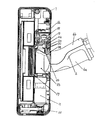
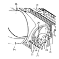
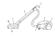
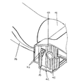
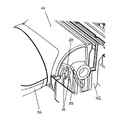
以下、本発明の第1の実施の形態について図面を用いて説明する。図1は本発明の吸込具の上部材を外した平面図、図2は図1の同吸込具の導線配線箇所拡大した平面図、図3は同吸込具の断面図、図4は同吸込具を構成するパイプとアーム部が連結した状態の側面図、図5は同吸込具を構成する上部材Bを外したパイプとアーム部が連結した状態の平面図、図6は同吸込具を構成する上部材Bを外した状態におけるアーム通常位置の斜視図、図7は図6の状態からアームが上方向にθ度回動した時の斜視図、図8は同吸込具を装着した電気掃除機の全体斜視図である。
(Embodiment 1)
Hereinafter, a first embodiment of the present invention will be described with reference to the drawings. 1 is a plan view with the upper member of the suction tool of the present invention removed, FIG. 2 is an enlarged plan view of a conductor wiring portion of the suction tool of FIG. 1, FIG. 3 is a sectional view of the suction tool, and FIG. FIG. 5 is a plan view of a state in which the pipe and the arm part are connected, and FIG. 6 is a view of the suction tool. FIG. 7 is a perspective view of the arm in a normal position with the upper member B removed, FIG. 7 is a perspective view when the arm is turned upward by θ degrees from the state of FIG. 6, and FIG. It is a whole perspective view of a vacuum cleaner.
図1〜図8において、1は吸込具であり電気掃除機用吸込具1は電気掃除機2に、ホース3、延長管4を介して接続される。ホース3および延長管4は内部が中空になっており、電気掃除2の後方に配置されている電動送風機5によって内部の空気が吸気、排出されることにより真空状態になり負圧がかかることで吸引風を発生させるものである。
1 to 8, reference numeral 1 denotes a suction tool, and the vacuum cleaner suction tool 1 is connected to the vacuum cleaner 2 through a hose 3 and an
電気掃除機用吸込具1の前後方向に対する後方部、略中央付近には前後もしくは左右に回動自在に保持されているパイプ6が設置されている。パイプ6は内部が中空状のパイプ部6aと上部材B6bで構成されており、一方を電気掃除5と延長管4ないしホース3を介して接続される。他方は止め具14によりアーム13と接続され、パイプ6と接続側と逆側のアームの開口部を吸引口7としてある。パイプ6はアーム13の中心軸に対し、左右約180度回動可能な構成としてある。アーム13は吸引具1の上部材15と下部材16に設けた軸受部に挟持され、アーム13は前後に回動可能な構成としてある。
A
一方、電気掃除機用吸込具1の底面は下方に開口する吸込口8を有し、吸込口8と吸引口7を繋ぎ、電気掃除機用吸込具1内部に形成される空間部を吸込室9として構成されている。
On the other hand, the bottom surface of the vacuum cleaner suction tool 1 has a
吸込室9内部には吸込口8に臨み、かつ吸込室9内側前壁に到達する位置に回転自在に軸支された回転ブラシ10が設けられている。回転ブラシ10はパイプ6が設置されている左右どちらか、もしくは同軸上に構成された駆動源11により動力を伝達されて回転運動をするように構成されている。一般的にパイプ6の左右どちらか一方に駆動源11を配置した場合には、回転ブラシ10と駆動源11はベルト12により張架されている。また、駆動源11には電動機(モータ)やタービンなどを使用されることが一般的であり、本発明では、モータを使用している。駆動源11を駆動させる電力は、電気掃除機2からホース3、延長管4内の導線(図示なし)、電気掃除機用吸込具1内の導線17、制御基板18、導線B19を経由して供給される。ここで、導線17はパイプ6、アーム13、下部材16内部に配線され、制御基板18に至る構成としてある。導線17の位置を規制するために、アーム13には導線17が通る側に孔部24を設け、孔部とアーム回動軸25間にリブB20と下部材16にはリブA21、リブC22、リブD23を設けている。リブB20、リブA21、リブC22、リブD23の各壁面は、同一面となるよう配置してある。特に、リブB20はアーム13の全回動位置で溝部A21の壁面と同一面となるよう、複数の直線、曲線で構成してある。また、リブB20はアーム13の外観面に対し、段落ちした形状としてある。また、リブA21は導線17を挿入する略U字状の溝部50を備えている。
Inside the suction chamber 9, there is provided a rotating
電気掃除機2を運転することにより電動送風機5が動き、電動送風機5の前方の空気を吸気し、後方に排出されることにより真空状態になり負圧がかかることで吸引風を発生させる。この負圧はホース3、延長管4を通じて電気掃除機用吸込具1に伝えられる。発生した負圧は電気掃除機用吸込具1では吸引風となり被掃除面上の塵埃を吸引することができる。
When the electric vacuum cleaner 2 is operated, the electric blower 5 moves, sucks in air in front of the electric blower 5, and discharges backward to generate a vacuum and generate a suction air by applying negative pressure. This negative pressure is transmitted to the vacuum cleaner suction tool 1 through the hose 3 and the
負圧はまずパイプ6を通じて、吸込口8を通して吸引口7に伝達される。主に塵埃は吸引口7から集塵されることになる。
The negative pressure is first transmitted through the
回転ブラシ10は駆動源11が電動機であった場合には電気掃除機2より電源の供給を受け回転駆動することができる。また、タービンだった場合には負圧により発生する吸引風によりタービンが駆動して、その動力が伝達される。回転ブラシ10は回転動作することにより被掃除面を機械力によって掻き出し、磨きの動作を加えて塵埃を集塵するものである。回転ブラシ10によって集塵された塵埃は吸込室9を通じて吸引されることになる。
When the
以上のように構成された電気掃除機用吸込具について、以下その動作、作用を説明する。 About the vacuum cleaner suction tool comprised as mentioned above, the operation | movement and an effect | action are demonstrated below.
電気掃除機用吸込具1には上部材15もしくは下部材16で構成した底面が下方に開口する吸込室9と、吸込室9の開口部を吸込口8とし、吸込口8には回転自在に軸支された回転ブラシ10と、吸込室9には回転ブラシ10を駆動する駆動源11であるモータと、電気掃除機用吸込具1の後方部であり長手方向の略中方付近に設けられたパイプ6と、パイプ6と吸込室9を連結し、上部材15と下部材16で挟持することで上下方向に回動するアーム13と、電気掃除機2本体からの電力を駆動源11であるモータへ伝達する導線17を有し、上部材15もしくは下部材16に導線17を配線するリブA21と、アーム13には導線17が通る孔部24と、孔部24の出口付近でかつリブA21付近のアーム13部にリブB20を設けることで、アーム13の全回動位置でアーム13部からの導線17の位置を規制する構成としたもので、下部材16にパイプ6、アーム13、導線17を組合せたユニット部品を組立てる時に、導線17がリブB20により位置が規制されるため、導線17が図12のような位置にいかず、リブA21間の正規位置に入ることができる。よって、組立作業上での不具合による導線17の噛み込みの恐れがなくなり、導線17断線、傷付けによる安全上の問題がなく、導線17不具合による再組立あるいは導線17断線が要因による他部品交換で発生するロスコストがなく、さらに、導線17噛み込みを対策するための別部品追加や導線17の引き回し作業あるいは、導線17の噛み込み有無確認のための作業チェックによる組立費増加、工数増加をなくすことが可能となる。
The vacuum cleaner suction tool 1 has a suction chamber 9 having a bottom surface formed by an
また、アーム13に設けたリブB20はリブA21導線配線用面に対して平行な位置関係としたもので、下部材16にパイプ6、アーム13、導線17を組合せたユニット部品を上方向から挿入して組立てる時に、リブB20とリブA21導線配線用面が平行であるため、リブB20が導線17配線時のガイドとなり、導線17が図12のような位置にいかず、導線17をリブA21間の正規位置に容易に配線することができる。さらに、リブC22、リブD23により、逆側の導線17位置も規制することができ、より導線17を正規位置に配線し易くなる。よって、組立作業上での不具合による導線17の噛み込みの恐れがなくなり、導線17断線、傷付けによる安全上の問題がなく、導線17不具合による再組立あるいは導線17断線が要因による他部品交換で発生するロスコストがなく、さらに、導線17噛み込みを対策するための別部品追加や導線17の引き回し作業あるいは、導線17の噛み込み有無確認のための作業チェックによる組立費増加、工数増加をなくすことが可能となる。
The rib B20 provided on the
また、アーム13に設けたリブB20は、アーム13に設けたリブB20と上部材15もしくは下部材16に設けたリブA21の壁面がアーム13の全回動位置で同一面なるよう、複数の直線、曲線形状の組み合わせで構成したもので、下部材16にパイプ6、アーム13、導線17を組合せたユニット部品を上方向から挿入して組立てる時に、ユニット部品がある程度傾斜していてもリブB20が導線17配線時のガイドの役割を果たすことができると共に、アーム全回動時においてリブB20による導線17への傷付け、挟み込み等を引き起こす恐れがない。よって、組立作業上、通常使用上での不具合による導線17の噛み込みの恐れがなくなり、導線17断線、傷付けによる安全上の問題がなく、導線17不具合による再組立あるいは導線17断線が要因による他部品交換で発生するロスコストがなく、さらに、導線17噛み込みを対策するための別部品追加や導線17の引き回し作業あるいは、導線17の噛み込み有無確認のための作業チェックによる組立費増加、工数増加をなくすことが可能となる。
Further, the rib B20 provided on the
また、アーム13に設けたリブB20は、アーム13の外観面に対し、段落ちの形状としたもので、段落ち形状でリブB20と吸込室9を構成する下部材16間に隙間を設けることで、異物付着および侵入等による摺動抵抗増加を防ぐことがきる。よって、異物付着および侵入等が原因によるパイプ6、アーム13の回動力増加を防ぐことができる。
The rib B20 provided on the
以上のように本発明にかかる電気掃除機用吸込具は、組立作業上での不具合による導線の噛み込みの恐れがなくなり、導線断線、傷付け等による安全上の問題を解消でき、同じく回転自在なパイプ、アームを有し、内部に導線を配線する電化機器製品に、幅広く応用可能である。 As described above, the vacuum cleaner suction tool according to the present invention eliminates the risk of the biting of the lead wire due to problems in assembly work, can solve the safety problem due to the wire breakage, scratching, etc., and is also rotatable. It can be widely applied to electrical equipment products that have pipes and arms and wire conductors inside.
1 電気掃除機用吸込具
6 パイプ
8 吸込口
9 吸込室
13 アーム
16 下部材
17 導線
20 リブB
21 リブA
24 孔部
DESCRIPTION OF SYMBOLS 1 Vacuum
21 Rib A
24 holes
Claims (3)
Priority Applications (1)
| Application Number | Priority Date | Filing Date | Title |
|---|---|---|---|
| JP2007080940A JP5040394B2 (en) | 2007-03-27 | 2007-03-27 | Vacuum cleaner suction tool |
Applications Claiming Priority (1)
| Application Number | Priority Date | Filing Date | Title |
|---|---|---|---|
| JP2007080940A JP5040394B2 (en) | 2007-03-27 | 2007-03-27 | Vacuum cleaner suction tool |
Publications (2)
| Publication Number | Publication Date |
|---|---|
| JP2008237461A true JP2008237461A (en) | 2008-10-09 |
| JP5040394B2 JP5040394B2 (en) | 2012-10-03 |
Family
ID=39909510
Family Applications (1)
| Application Number | Title | Priority Date | Filing Date |
|---|---|---|---|
| JP2007080940A Expired - Fee Related JP5040394B2 (en) | 2007-03-27 | 2007-03-27 | Vacuum cleaner suction tool |
Country Status (1)
| Country | Link |
|---|---|
| JP (1) | JP5040394B2 (en) |
Cited By (2)
| Publication number | Priority date | Publication date | Assignee | Title |
|---|---|---|---|---|
| JP2015221150A (en) * | 2014-05-23 | 2015-12-10 | 三菱電機株式会社 | Vacuum cleaner |
| JP2018011737A (en) * | 2016-07-21 | 2018-01-25 | 日立アプライアンス株式会社 | Suction port body and vacuum cleaner including the same |
Citations (2)
| Publication number | Priority date | Publication date | Assignee | Title |
|---|---|---|---|---|
| JPH10262876A (en) * | 1997-03-28 | 1998-10-06 | Mitsubishi Electric Corp | Suction equipment for vacuum cleaner |
| JP2000217755A (en) * | 1999-01-28 | 2000-08-08 | Toshiba Tec Corp | Electric cleaner and suction port body therefor |
-
2007
- 2007-03-27 JP JP2007080940A patent/JP5040394B2/en not_active Expired - Fee Related
Patent Citations (2)
| Publication number | Priority date | Publication date | Assignee | Title |
|---|---|---|---|---|
| JPH10262876A (en) * | 1997-03-28 | 1998-10-06 | Mitsubishi Electric Corp | Suction equipment for vacuum cleaner |
| JP2000217755A (en) * | 1999-01-28 | 2000-08-08 | Toshiba Tec Corp | Electric cleaner and suction port body therefor |
Cited By (2)
| Publication number | Priority date | Publication date | Assignee | Title |
|---|---|---|---|---|
| JP2015221150A (en) * | 2014-05-23 | 2015-12-10 | 三菱電機株式会社 | Vacuum cleaner |
| JP2018011737A (en) * | 2016-07-21 | 2018-01-25 | 日立アプライアンス株式会社 | Suction port body and vacuum cleaner including the same |
Also Published As
| Publication number | Publication date |
|---|---|
| JP5040394B2 (en) | 2012-10-03 |
Similar Documents
| Publication | Publication Date | Title |
|---|---|---|
| JP2008132299A (en) | Vacuum cleaner | |
| US9826870B2 (en) | Robotic vacuum cleaner | |
| JP5656327B2 (en) | Cleaning fan for ceiling fan | |
| JP5040394B2 (en) | Vacuum cleaner suction tool | |
| JP4978223B2 (en) | Vacuum cleaner suction tool and vacuum cleaner using the same | |
| JP2000354567A (en) | Vacuum cleaner and nozzle body thereof | |
| JP3597429B2 (en) | Suction port for vacuum cleaner and vacuum cleaner | |
| JP6853586B2 (en) | Dust remover and vacuum cleaner system | |
| JP6876984B2 (en) | Suction tool | |
| JP4900099B2 (en) | Vacuum cleaner suction tool and vacuum cleaner using the same | |
| JP2008099924A (en) | Suction head of vacuum cleaner | |
| JP3797461B2 (en) | Vacuum cleaner and its suction port | |
| KR100598599B1 (en) | Turbine brush of a vacuum cleaner | |
| JP2013056385A (en) | Power tool dust collecting device and power tool | |
| KR200161823Y1 (en) | A connect apparatus of indraft hose in center dust collection vacuum cleaner | |
| JP2000354568A5 (en) | ||
| JP2000354563A (en) | Vacuum cleaner and nozzle body thereof | |
| JP2017140256A (en) | Suction tool for vacuum cleaner for bedding and vacuum cleaner | |
| KR102451129B1 (en) | An underground distribution line connection type support device capable of detecting abnormalities | |
| CN214595733U (en) | Rolling brush mechanism and sweeping robot | |
| JP4540501B2 (en) | Connecting device for vacuum cleaner and suction tool for vacuum cleaner provided with the same | |
| JP2718655B2 (en) | Electric vacuum cleaner | |
| JP2849371B2 (en) | Electric vacuum cleaner | |
| JP2004113540A (en) | Vacuum cleaner | |
| JPH0795945A (en) | Vacuum cleaner |
Legal Events
| Date | Code | Title | Description |
|---|---|---|---|
| A621 | Written request for application examination |
Free format text: JAPANESE INTERMEDIATE CODE: A621 Effective date: 20100226 |
|
| RD01 | Notification of change of attorney |
Free format text: JAPANESE INTERMEDIATE CODE: A7421 Effective date: 20100312 |
|
| A977 | Report on retrieval |
Free format text: JAPANESE INTERMEDIATE CODE: A971007 Effective date: 20111110 |
|
| A131 | Notification of reasons for refusal |
Free format text: JAPANESE INTERMEDIATE CODE: A131 Effective date: 20111115 |
|
| A521 | Request for written amendment filed |
Free format text: JAPANESE INTERMEDIATE CODE: A523 Effective date: 20120110 |
|
| TRDD | Decision of grant or rejection written | ||
| A01 | Written decision to grant a patent or to grant a registration (utility model) |
Free format text: JAPANESE INTERMEDIATE CODE: A01 Effective date: 20120612 |
|
| A01 | Written decision to grant a patent or to grant a registration (utility model) |
Free format text: JAPANESE INTERMEDIATE CODE: A01 |
|
| A61 | First payment of annual fees (during grant procedure) |
Free format text: JAPANESE INTERMEDIATE CODE: A61 Effective date: 20120625 |
|
| R151 | Written notification of patent or utility model registration |
Ref document number: 5040394 Country of ref document: JP Free format text: JAPANESE INTERMEDIATE CODE: R151 |
|
| FPAY | Renewal fee payment (event date is renewal date of database) |
Free format text: PAYMENT UNTIL: 20150720 Year of fee payment: 3 |
|
| LAPS | Cancellation because of no payment of annual fees |