JP2008232147A - Turbomachine fan - Google Patents
Turbomachine fan Download PDFInfo
- Publication number
- JP2008232147A JP2008232147A JP2008065739A JP2008065739A JP2008232147A JP 2008232147 A JP2008232147 A JP 2008232147A JP 2008065739 A JP2008065739 A JP 2008065739A JP 2008065739 A JP2008065739 A JP 2008065739A JP 2008232147 A JP2008232147 A JP 2008232147A
- Authority
- JP
- Japan
- Prior art keywords
- disk
- platform
- upstream
- lug
- fan
- Prior art date
- Legal status (The legal status is an assumption and is not a legal conclusion. Google has not performed a legal analysis and makes no representation as to the accuracy of the status listed.)
- Pending
Links
Images


Classifications
-
- F—MECHANICAL ENGINEERING; LIGHTING; HEATING; WEAPONS; BLASTING
- F04—POSITIVE - DISPLACEMENT MACHINES FOR LIQUIDS; PUMPS FOR LIQUIDS OR ELASTIC FLUIDS
- F04D—NON-POSITIVE-DISPLACEMENT PUMPS
- F04D29/00—Details, component parts, or accessories
- F04D29/60—Mounting; Assembling; Disassembling
- F04D29/64—Mounting; Assembling; Disassembling of axial pumps
- F04D29/644—Mounting; Assembling; Disassembling of axial pumps especially adapted for elastic fluid pumps
-
- F—MECHANICAL ENGINEERING; LIGHTING; HEATING; WEAPONS; BLASTING
- F01—MACHINES OR ENGINES IN GENERAL; ENGINE PLANTS IN GENERAL; STEAM ENGINES
- F01D—NON-POSITIVE DISPLACEMENT MACHINES OR ENGINES, e.g. STEAM TURBINES
- F01D11/00—Preventing or minimising internal leakage of working-fluid, e.g. between stages
- F01D11/005—Sealing means between non relatively rotating elements
- F01D11/006—Sealing the gap between rotor blades or blades and rotor
- F01D11/008—Sealing the gap between rotor blades or blades and rotor by spacer elements between the blades, e.g. independent interblade platforms
-
- F—MECHANICAL ENGINEERING; LIGHTING; HEATING; WEAPONS; BLASTING
- F04—POSITIVE - DISPLACEMENT MACHINES FOR LIQUIDS; PUMPS FOR LIQUIDS OR ELASTIC FLUIDS
- F04D—NON-POSITIVE-DISPLACEMENT PUMPS
- F04D29/00—Details, component parts, or accessories
- F04D29/26—Rotors specially for elastic fluids
- F04D29/32—Rotors specially for elastic fluids for axial flow pumps
- F04D29/321—Rotors specially for elastic fluids for axial flow pumps for axial flow compressors
- F04D29/322—Blade mountings
-
- F—MECHANICAL ENGINEERING; LIGHTING; HEATING; WEAPONS; BLASTING
- F01—MACHINES OR ENGINES IN GENERAL; ENGINE PLANTS IN GENERAL; STEAM ENGINES
- F01D—NON-POSITIVE DISPLACEMENT MACHINES OR ENGINES, e.g. STEAM TURBINES
- F01D5/00—Blades; Blade-carrying members; Heating, heat-insulating, cooling or antivibration means on the blades or the members
- F01D5/30—Fixing blades to rotors; Blade roots ; Blade spacers
- F01D5/32—Locking, e.g. by final locking blades or keys
- F01D5/323—Locking of axial insertion type blades by means of a key or the like parallel to the axis of the rotor
-
- F—MECHANICAL ENGINEERING; LIGHTING; HEATING; WEAPONS; BLASTING
- F05—INDEXING SCHEMES RELATING TO ENGINES OR PUMPS IN VARIOUS SUBCLASSES OF CLASSES F01-F04
- F05D—INDEXING SCHEME FOR ASPECTS RELATING TO NON-POSITIVE-DISPLACEMENT MACHINES OR ENGINES, GAS-TURBINES OR JET-PROPULSION PLANTS
- F05D2220/00—Application
- F05D2220/30—Application in turbines
- F05D2220/36—Application in turbines specially adapted for the fan of turbofan engines
-
- Y—GENERAL TAGGING OF NEW TECHNOLOGICAL DEVELOPMENTS; GENERAL TAGGING OF CROSS-SECTIONAL TECHNOLOGIES SPANNING OVER SEVERAL SECTIONS OF THE IPC; TECHNICAL SUBJECTS COVERED BY FORMER USPC CROSS-REFERENCE ART COLLECTIONS [XRACs] AND DIGESTS
- Y02—TECHNOLOGIES OR APPLICATIONS FOR MITIGATION OR ADAPTATION AGAINST CLIMATE CHANGE
- Y02T—CLIMATE CHANGE MITIGATION TECHNOLOGIES RELATED TO TRANSPORTATION
- Y02T50/00—Aeronautics or air transport
- Y02T50/60—Efficient propulsion technologies, e.g. for aircraft
Abstract
Description
本発明は、航空機のターボファンまたはターボプロップなどのターボ機械のファンに関する。 The present invention relates to a turbomachine fan such as an aircraft turbofan or turboprop.
知られている態様において、ターボ機械ファンは、ディスクの周囲に形成される実質的に軸方向のスロットでその根元部が係合されて保持される複数のブレードを担持するロータディスクを備える。これらのブレードは、プラットフォームとの半径方向の内側端部で結合され、これらのプラットフォームは、ターボ機械に入る空気流用の環状流路を内部に画定する。 In a known manner, a turbomachine fan comprises a rotor disk carrying a plurality of blades whose roots are engaged and held in substantially axial slots formed around the disk. These blades are coupled at the radially inner end with the platform, and these platforms define an annular flow path for air flow into the turbomachine therein.
ファンの各ブレードは、プラットフォームと単一部品に形成されてもよい。ブレードは、その場合には相対的に重く、ブレード根元部における相当の機械的応力によって動作中に現れる因子が、場合によっては、破損または分割をこの根元部に生じる原因となる。さらに、このタイプのファンブレードの損失は、ターボ機械に著しい損傷を生じる結果となり、ファンの不つり合いを相当増大する。 Each blade of the fan may be formed in a single piece with the platform. The blade is then relatively heavy, and factors that appear during operation due to considerable mechanical stress at the blade root can in some cases cause breakage or splitting at this root. In addition, the loss of this type of fan blade results in significant damage to the turbomachine and significantly increases fan imbalance.
ファンブレードおよびプラットフォームはまた、互いに独立であってもよい。プラットフォームは、ブレード間プラットフォームと呼ばれ、2つの隣接ブレード間でファンディスクにそれぞれ装着されて固着される。各プラットフォームは、プラットフォームのラグにおけるオリフィスおよびディスクのラグの対応するオリフィスに取り付けられたナットおよびボルト型またはスラグから構成される多数のシステムによって、ディスクの対応するラグに固着される内部半径方向のラグを備える。これらのブレードは、プラットフォームに連結されないため、したがって、ブレード根元部が動作中に受ける機械的応力を相当低減することを可能にする。次に、ファンを軽量化し、したがってターボ機械の性能を増大させるために、ブレード根元部のサイズを減少することも可能である。さらに、ファンブレードを喪失した場合には、ブレードの両側に1つずつ位置する2つのプラットフォームは依然として、ディスク上に置かれ、ターボ機械においてさらなる損傷を生じないようにする。これらの2つのプラットフォームはさらに、ブレードの半径方向内側端部と接触する喪失したブレードがデブリを生じないようすることによって、周囲のファンブレードを保護することを可能にする。 The fan blade and platform may also be independent of each other. The platform is referred to as an inter-blade platform and is mounted and secured to a fan disk between two adjacent blades. Each platform has an internal radial lug secured to the corresponding lug of the disk by a number of systems consisting of nuts and bolts or slugs attached to the orifice in the platform lug and the corresponding orifice of the disk lug. Is provided. Since these blades are not connected to the platform, it is therefore possible to considerably reduce the mechanical stresses experienced by the blade root during operation. It is then possible to reduce the blade root size in order to reduce the fan weight and thus increase the performance of the turbomachine. In addition, if the fan blade is lost, the two platforms, one on each side of the blade, are still placed on the disk to prevent further damage in the turbomachine. These two platforms further allow the surrounding fan blades to be protected by preventing lost blades in contact with the radially inner ends of the blades from causing debris.
しかし、ブレード間プラットフォームの使用は、上記で明記した理由のために有利であるが、ナットおよびボルト型またはスラグから構成されるシステムによって、これらのプラットフォームを固着することは、約1mの直径を有する小さなエンジンの場合に達成することは困難であることが分かっており、不可能である場合もある。この理由は、ナットおよびボルト型から構成される固着システムが、きわめて分厚く、小さな直径のエンジンに用いることができないことである。さらに、2つの隣接するファンブレード間の間隔およびプラットフォームの半径方向の内部に位置する空間は、これらの固着システムを締め付けるために必要な工具を操作することができるほど十分ではない。したがって、製作業者は、小さな直径のエンジンに組み込み型プラットフォームを有するブレードを用いることを強いられる。 However, the use of inter-blade platforms is advantageous for the reasons specified above, but securing these platforms by a system consisting of nuts and bolts or slugs has a diameter of about 1 m. It has proved difficult and sometimes impossible to achieve with small engines. The reason for this is that the fastening system consisting of a nut and bolt type is very thick and cannot be used for small diameter engines. Furthermore, the spacing between two adjacent fan blades and the space located in the radial interior of the platform is not sufficient to operate the tools necessary to tighten these fastening systems. Thus, manufacturers are forced to use blades with embedded platforms in small diameter engines.
本発明の具体的な目的は、これらの種々の問題に対して、簡単かつ経済的で効果的な解決策を提供すると同時に、特に小さな直径のエンジンにおいてブレード間プラットフォームの使用を可能にすることである。 A specific object of the present invention is to provide a simple, economical and effective solution to these various problems, while at the same time enabling the use of a blade-to-blade platform, especially in small diameter engines. is there.
したがって、本発明は、その根元部がロータディスクの周囲のスロットに取り付けられる複数のブレードと、ブレード根元部を取り付けるためのスロットの間で、ディスクを対応するラグに固着するための半径方向のラグを有するブレード間プラットフォームとを備え、各プラットフォームが、プラットフォームのラグにおけるオリフィスおよびディスクのラグの対応するオリフィスに挿入されるピンによってディスクに固着される、ターボ機械ファンを提供する。 Accordingly, the present invention provides a radial lug for securing a disk to a corresponding lug between a plurality of blades whose roots are mounted in slots around the rotor disk and a slot for mounting the blade root. A turbomachine fan, wherein each platform is secured to a disk by a pin inserted into an orifice in the platform lug and a corresponding orifice in the disk lug.
本発明によれば、各ブレード間プラットフォームは、プラットフォームの全体的な軸方向の寸法に沿って実質的に延在し、プラットフォームのラグにおけるオリフィスおよびディスクのラグの対応するオリフィスの中で上流または下流から実質的に軸方向に係合する単独の構成要素を用いて、ディスクに固着される。ピンは、ファンの上流または下流から取り付けられ、プラットフォームの半径方向の内部に位置する空間において、特定の工具の操作を必要としない。したがって、小さな直径のエンジンを含め、任意のタイプのエンジンにブレード間プラットフォームを用いることを可能にする。 In accordance with the present invention, each inter-blade platform extends substantially along the overall axial dimension of the platform, upstream or downstream within the orifice in the platform lug and the corresponding orifice in the disk lug. Are secured to the disk using a single component that engages substantially axially. The pins are mounted from upstream or downstream of the fan and do not require any specific tool manipulation in the space located radially inside the platform. Thus, it makes it possible to use a blade-to-blade platform for any type of engine, including small diameter engines.
これらのプラットフォームのそれぞれは、その上流端部および下流端部のそれぞれに、半径方向のラグを備えてもよい。 Each of these platforms may include radial lugs at each of its upstream and downstream ends.
有利には、各プラットフォームは、ディスクの上流ラグに接触するその上流端部およびディスクに追加されて固着される下流の環状側板のラグに接触するその下流端部で、軸方向かつ半径方向に担持される。 Advantageously, each platform is supported axially and radially at its upstream end in contact with the upstream lug of the disk and its downstream end in contact with the lug of the downstream annular side plate that is additionally secured to the disk. Is done.
プラットフォームとディスクとの間およびプラットフォームと環状側板との間の上流および下流の担持接触部は、ディスクにおけるプラットフォームの正確な位置決めを確保し、プラットフォームのラグにおけるオリフィスが、ディスクおよび環状端部板のラグにおけるオリフィスと正確に整列されることを確保する。 The upstream and downstream bearing contacts between the platform and the disk and between the platform and the annular side plate ensure accurate positioning of the platform in the disk, and the orifice in the platform lug is connected to the disk and annular end plate lugs. Ensure that it is accurately aligned with the orifice in the.
好ましくは、ピンは、上流からプラットフォームおよびディスクのラグにおけるオリフィスに挿入され、その上流端部に、ディスクに追加されて固着される上流の環状側板によって、プラットフォームの上流ラグに対して当てられ続ける頭部を備える。 Preferably, the pin is inserted into the orifice in the platform and disk lug from upstream and is headed against the upstream lug of the platform by an upstream annular side plate that is added and secured to the disk at its upstream end. A part.
したがって、ピンは、上流の環状側板およびプラットフォームの上流ラグに対して軸方向に担持されることによって、軸方向に不動である。この不動化により、特定の工具を用いなくて済む。 Thus, the pin is axially immobile by being axially carried against the upstream annular side plate and the platform upstream lug. This immobilization eliminates the need for a specific tool.
取り付け位置において、ピンは好ましくは、ディスクの回転軸に対して斜めに延在する。ピンは、例えば、外側に向かって下流に延在してもよい。 In the mounting position, the pin preferably extends obliquely with respect to the axis of rotation of the disk. The pin may, for example, extend downstream toward the outside.
本発明はまた、上述のタイプのファンを備える航空機ターボファンなどのターボ機械に関する。 The invention also relates to a turbomachine, such as an aircraft turbofan, comprising a fan of the type described above.
本発明はさらに、上述のようにファンのディスクにブレード間プラットフォームを固着するためのピンであって、本体より大きい直径または横寸法を有する頭部に一端で接合される実質的に円筒形の細長い直線形状の本体を備えるピンに関する。 The present invention further includes a pin for securing the inter-blade platform to the fan disk as described above, and having a substantially cylindrical elongated shape joined at one end to a head having a larger diameter or lateral dimension than the body. The present invention relates to a pin including a linear main body.
ピンは、チタンまたは複合材料などの強力で軽量材料から製造されてもよい。 The pin may be manufactured from a strong and lightweight material such as titanium or a composite material.
添付図面を参照して非限定的な実施例によって与えられる以下の詳細を読めば、本発明は、よりよく理解され、本発明の他の利点および特徴は、明白となるであろう。 The invention will be better understood and other advantages and features of the invention will become apparent upon reading the following details given by way of non-limiting examples with reference to the accompanying drawings.
第一に、ターボ機械ファン10を概略的に示す図1を参照されたい。ターボ機械ファン10は、タービンシャフト14の上流端部に取り付けられ、その周囲に、ファンの回転軸18を中心にして均一に分散され、その間にブレード間プラットフォーム20が取り付けられる複数のブレード16を担持するディスク12を備える。
First, please refer to FIG. 1, which schematically shows a
ブレード16は、プラットフォーム20と共に、ターボ機械に入る空気流22のための環状流路を画定するナセル(図示せず)によって外側から包囲される。
The
その周囲で、ディスク12は、ディスク12の全長にわたって長手方向に延在するスロット23およびリブ24の交互構成を備える(図3)。それらの半径方向内部の端部で、ブレード16は、上流からディスクのスロット23の中に軸方向に係合し、これらのスロット23と連結する形状によって協働し、ブレード16がディスク12上で半径方向に保持されることを確保するための根元部を備える。ブレード根元部は、例えば、ダブテイル形状を有する。
At its periphery, the
ブレード16は、ディスク12の下流面に追加されて固着される環状側板26によって、軸方向の下流に保持される。示された実施例において、側板26は、ナットおよびボルト型の手段29を用いて、ディスク12の半径方向の外部下流ラグ28に固着される。この下流側板26は、その半径方向外側端部で、ブレード間プラットフォーム20と整列される内部ファンケーシング30と封止して協働する。
The
シム32は、ディスク12上で半径方向にブレード16を不動にするためにブレード根元部とスロット23の下部との間に上流から軸方向に挿入される(図1および図4)。その上流端部で、このシム32は、上流方向においてブレードを軸方向に保持するために、ブレード根元部の上流端部に接触して軸方向に担持する半径方向リップ34を備える。シム32は、ディスク12の上流面に追加されて固着され、シム32の半径方向リップに接触してその半径方向外側端部に担持する上流環状側板36によって、軸方向に不動化される。上流環状側板36の半径方向内側端部は、下流に位置するファンディスクの環状フランジ38と、上流に位置するターボ機械の入口円錐42の環状フランジ40との間に介在され、ナットおよびボルト型の手段29を用いて、これらのフランジ38、40の間で締結される。入口円錐42は、ブレード間プラットフォーム20と整列される。
The
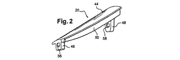
各プラットフォーム20は、実質的に円周方向の向きの壁44と、一方は上流に、一方は下流にあり、壁44の内面から半径方向内側に延在する2つの半径方向ラグ46、48と、を備える。2つのラグ46および48は、壁44の内面に沿って上流ラグ46から下流ラグ48まで延在する少なくとも1つの長手方向の補強リブ50によって相互接続される(図2)。
Each
各プラットフォーム20は、2つの隣接ブレード16の間でディスク12のリブ24上に位置決めされ、ディスク12の半径方向外側上流ラグ52および下流環状側板26に担持される半径方向外側ラグ54に接触して軸方向かつ半径方向に担持する。さらに正確に言えば、プラットフォーム20のラグ46および48は、ディスク12のラグ52および下流環状側板26のラグ54に接触して下流方向において軸方向に担持し、プラットフォーム20の壁44またはリブ50は、ディスク12の上流ラグ52の半径方向外側端部に接触してその上流端部で半径方向に担持し、プラットフォーム20のリブ50は、下流環状側板26のラグ54の半径方向外側端部に接触してその下流端部で半径方向に担持する。これらの担持接触は、ディスク12のリブ24上におけるプラットフォーム20の正確な位置決めを確保し、ディスク12および下流環状側板26のラグにおけるオリフィス60および62とプラットフォーム20のラグにおけるオリフィス56および58の軸方向の整列を確保する(図1)。
Each
本発明によれば、プラットフォーム20は、上流からプラットフォーム20のラグにおけるオリフィス56、58およびディスク12および下流環状側板26のラグのオリフィス60および62に実質的に軸方向に係合するピン64によって、ディスク12のリブ24上で不動化される。
In accordance with the present invention, the
このピン64は、実質的に円筒であり、プラットフォーム20の半径方向内側で上述のオリフィス56、58、60、62を通って延在することを意図した細長い直線形状の本体66を備える。示された実施例において、ピン64は、ファン10の回転軸18に対して傾斜されており、外側に向かって下流に延在する。
The
ピン64の本体66は、その上流端部で本体66より大きな直径または大きな横寸法を有する頭部68に接合され、この頭部68は、下流方向に向けられ、プラットフォーム20のラグ46の上流面と当接することを意図する半径方向の面を有し、上流方向においてプラットフォーム20を軸方向に保持する。ピン64の頭部68は、ピン64の頭部68の上流端部に接触してその半径方向外側端部で担持する上流環状側板36によって、この位置で不動化される。
The
本発明によるファン10は、以下の方法で組み立てられる。下流環状側板26が、ナットおよびボルト型の手段29を用いて、ディスク12に固着される(図3)。ブレード16の根元部が次に、ブレード16が下流環状側板26に対して当接するまで、ディスクのスロット23に上流から軸方向に係合される。シム32が次に、ディスク12上で半径方向でブレード16を不動化するために、ブレード根元部の下に挿入される(図4)。プラットフォーム20が次に、ディスク12のリブ24上に取り付けられる。各プラットフォーム20は、プラットフォーム20がディスク12の上流ラグ52および下流環状側板26のラグ54に接触して、軸方向かつ半径方向に担持するまで、ディスク12のリブ24の上に持ってきて、半径方向内側に移動され得る。ピン64は、ピン64の上流頭部68がプラットフォーム20の上流ラグ46の上流面に対して当接するまで、上流側からプラットフォーム20のラグ46および48におけるオリフィス56および58をディスク12および環状側板26のラグにおけるオリフィス60および62を介して、実質的に軸方向に係合される(図1および図4)。上流環状側板36が、次に、組立品を固定するために、ディスク12の上流フランジ38に追加されて固着される(図1)。
The
本発明によるファン10の使用は、小さなエンジンの場合に特に有利であることが分かっているが、大きなエンジンの場合にも等しく用いられ得る。この目的のために、1つまたは複数の追加の半径方向のラグが、プラットフォーム20上に設けられ得、対応する半径方向のラグが、ディスク12のリブ24上に設けられ得、これらのラグは、ピン64が通過するオリフィスを有する。これは、ターボ機械の動作中、プラットフォーム20の屈曲移動を制限することを可能にする。
The use of the
ディスク12および下流環状側板26が、単一部品に製造され得る。
The
プラットフォーム20は、ブレード16に関して用いられる材料と同一の材料、例えば金属、あるいは複合材料またはチタンなどの強力な軽量材料から製造され得る。
10 ターボ機械
12 ディスク
14 タービンシャフト
16 ブレード
18 ファンの回転軸
20 ブレード間プラットフォーム
22 空気流
23 スロット
24 リブ
26 下流環状側板
28 下流ラグ
29 ナットおよびボルト型の手段
30 内部ファンケーシング
32 シム
36 上流環状側板
38、40 環状フランジ
42 入口円錐
44 壁
46、48、52、54 ラグ
50 補強リブ
56、58、60、62 オリフィス
64 ピン
66 ピン本体
68 ピン頭部
DESCRIPTION OF
Claims (10)
Applications Claiming Priority (1)
| Application Number | Priority Date | Filing Date | Title |
|---|---|---|---|
| FR0701903A FR2913734B1 (en) | 2007-03-16 | 2007-03-16 | TURBOMACHINE BLOWER |
Related Child Applications (1)
| Application Number | Title | Priority Date | Filing Date |
|---|---|---|---|
| JP2013164773A Division JP5719888B2 (en) | 2007-03-16 | 2013-08-08 | Turbomachine fan |
Publications (1)
| Publication Number | Publication Date |
|---|---|
| JP2008232147A true JP2008232147A (en) | 2008-10-02 |
Family
ID=38657661
Family Applications (2)
| Application Number | Title | Priority Date | Filing Date |
|---|---|---|---|
| JP2008065739A Pending JP2008232147A (en) | 2007-03-16 | 2008-03-14 | Turbomachine fan |
| JP2013164773A Active JP5719888B2 (en) | 2007-03-16 | 2013-08-08 | Turbomachine fan |
Family Applications After (1)
| Application Number | Title | Priority Date | Filing Date |
|---|---|---|---|
| JP2013164773A Active JP5719888B2 (en) | 2007-03-16 | 2013-08-08 | Turbomachine fan |
Country Status (7)
| Country | Link |
|---|---|
| US (1) | US8246310B2 (en) |
| EP (1) | EP1970537B1 (en) |
| JP (2) | JP2008232147A (en) |
| CA (1) | CA2625319C (en) |
| DE (1) | DE602008000388D1 (en) |
| FR (1) | FR2913734B1 (en) |
| RU (1) | RU2459120C2 (en) |
Cited By (3)
| Publication number | Priority date | Publication date | Assignee | Title |
|---|---|---|---|---|
| JP2014513765A (en) * | 2011-05-04 | 2014-06-05 | スネクマ | Turbomachine rotor with blade axial holding means |
| JP2018525558A (en) * | 2015-07-08 | 2018-09-06 | サフラン・エアクラフト・エンジンズ | Rotating assembly of an aero turbomachine with retrofit fan blade platform |
| JP2019512639A (en) * | 2016-03-21 | 2019-05-16 | サフラン エアークラフト エンジンズ | Wing pedestal and fan disk for aircraft turbine engines |
Families Citing this family (33)
| Publication number | Priority date | Publication date | Assignee | Title |
|---|---|---|---|---|
| FR2961847B1 (en) * | 2010-06-25 | 2012-08-17 | Snecma | AUBES MOBILE WHEEL IN COMPOSITE MATERIAL FOR A TURBINE GAS TURBINE ENGINE WITH A WAVEBASE / TIGHTENING DISC |
| FR2965843B1 (en) * | 2010-10-06 | 2012-11-09 | Snecma | ROTOR FOR TURBOMACHINE |
| FR2974863B1 (en) * | 2011-05-06 | 2015-10-23 | Snecma | TURBOMACHINE BLOWER DISK |
| US9303520B2 (en) | 2011-12-09 | 2016-04-05 | General Electric Company | Double fan outlet guide vane with structural platforms |
| US9267386B2 (en) | 2012-06-29 | 2016-02-23 | United Technologies Corporation | Fairing assembly |
| US10344601B2 (en) | 2012-08-17 | 2019-07-09 | United Technologies Corporation | Contoured flowpath surface |
| WO2014088673A2 (en) * | 2012-09-20 | 2014-06-12 | United Technologies Corporation | Gas turbine engine fan spacer platform attachments |
| FR3004227B1 (en) * | 2013-04-09 | 2016-10-21 | Snecma | BLOWER DISK FOR A TURBOJET ENGINE |
| EP3047109B1 (en) | 2013-09-18 | 2020-04-15 | United Technologies Corporation | Fan platform with leading edge tab |
| US10539148B2 (en) | 2013-10-11 | 2020-01-21 | United Technologies Corporation | Fan rotor with integrated platform attachment |
| US10024234B2 (en) * | 2014-09-08 | 2018-07-17 | Rolls-Royce Deutschland Ltd & Co Kg | Panels of a fan of a gas turbine |
| DE102014217884A1 (en) * | 2014-09-08 | 2016-03-24 | Rolls-Royce Deutschland Ltd & Co Kg | Filling elements of a fan of a gas turbine |
| US9909430B2 (en) | 2014-11-13 | 2018-03-06 | Rolls-Royce North American Technologies Inc. | Turbine disk assembly including seperable platforms for blade attachment |
| FR3038654B1 (en) * | 2015-07-08 | 2017-08-04 | Snecma | ASSEMBLY OF A REPORTED PLATFORM OF BLOWER BLADE ON A BLOWER DISK |
| US9976426B2 (en) * | 2015-07-21 | 2018-05-22 | United Technologies Corporation | Fan platform with stiffening feature |
| FR3051174B1 (en) | 2016-05-10 | 2018-06-01 | Safran Aircraft Engines | FRONT ROTATING PART OF AN AIRCRAFT TURBOMACHINE RECEIVER WITH IMPROVED DESIGN FOR RELEASE OF THE CONE TIP |
| FR3053083B1 (en) * | 2016-06-22 | 2019-11-01 | Safran Aircraft Engines | RING OF WHEEL FAIRING IN AUBES |
| FR3057908B1 (en) | 2016-10-21 | 2019-11-22 | Safran Aircraft Engines | ROTARY ASSEMBLY OF A TURBOMACHINE PROVIDED WITH AN AXIAL MAINTAINING SYSTEM OF A DAWN |
| FR3066552B1 (en) | 2017-05-22 | 2021-11-19 | Safran Aircraft Engines | ASSEMBLY ON A TURBOMACHINE SHAFT OF A MONOBLOC BLADE DISC AND A LOW PRESSURE COMPRESSOR ROTOR WITH AT LEAST TWO STAGES OF MOBILE BLADES |
| US10280767B2 (en) * | 2017-08-29 | 2019-05-07 | United Technologies Corporation | Fan hub attachment for leading and trailing edges of fan blades |
| US10612400B2 (en) * | 2017-11-27 | 2020-04-07 | United Technologies Corporation | Composite fan platform lug reinforcement |
| US10781702B2 (en) | 2018-03-08 | 2020-09-22 | Raytheon Technologies Corporation | Fan spacer for a gas turbine engine |
| US10724390B2 (en) | 2018-03-16 | 2020-07-28 | General Electric Company | Collar support assembly for airfoils |
| US11174741B2 (en) * | 2018-04-19 | 2021-11-16 | Raytheon Technologies Corporation | Platform for an airfoil of a gas turbine engine |
| FR3082876B1 (en) * | 2018-06-21 | 2021-01-22 | Safran Aircraft Engines | BLOWER INCLUDING A PLATFORM AND A LOCK LOCK |
| US11092020B2 (en) * | 2018-10-18 | 2021-08-17 | Raytheon Technologies Corporation | Rotor assembly for gas turbine engines |
| FR3089548B1 (en) * | 2018-12-07 | 2021-03-19 | Safran Aircraft Engines | BLOWER INCLUDING AN INTER-BLADE PLATFORM FIXED UPSTREAM BY A VIROLE |
| FR3094400B1 (en) | 2019-03-28 | 2022-12-16 | Safran | Fan rotor for turbomachinery |
| FR3107923B1 (en) | 2020-03-03 | 2022-02-04 | Safran Aircraft Engines | METHOD FOR MANUFACTURING A COMPOSITE PLATFORM FOR AN AIRCRAFT TURBOMACHINE FAN |
| FR3107915B1 (en) | 2020-03-03 | 2022-02-04 | Safran Aircraft Engines | METHOD FOR MANUFACTURING A COMPOSITE PLATFORM FOR AN AIRCRAFT TURBOMACHINE FAN |
| FR3107914B1 (en) | 2020-03-03 | 2022-02-04 | Safran Aircraft Engines | COMPOSITE PLATFORM FOR AN AIRCRAFT TURBOMACHINE FAN |
| FR3109794B1 (en) | 2020-05-04 | 2022-08-12 | Safran Aircraft Engines | PLATFORM FOR A FAN ROTOR OF AN AIRCRAFT TURBOMACHINE |
| FR3109793B1 (en) | 2020-05-04 | 2022-08-12 | Safran Aircraft Engines | PLATFORM FOR A FAN ROTOR OF AN AIRCRAFT TURBOMACHINE |
Citations (1)
| Publication number | Priority date | Publication date | Assignee | Title |
|---|---|---|---|---|
| JP2002195103A (en) * | 2000-11-27 | 2002-07-10 | General Electric Co <Ge> | Blade spacer |
Family Cites Families (16)
| Publication number | Priority date | Publication date | Assignee | Title |
|---|---|---|---|---|
| FR989839A (en) * | 1949-06-28 | 1951-09-13 | Cem Comp Electro Mec | Blade for turbo-machine |
| US2751189A (en) * | 1950-09-08 | 1956-06-19 | United Aircraft Corp | Blade fastening means |
| US4621979A (en) * | 1979-11-30 | 1986-11-11 | United Technologies Corporation | Fan rotor blades of turbofan engines |
| US5277548A (en) * | 1991-12-31 | 1994-01-11 | United Technologies Corporation | Non-integral rotor blade platform |
| GB9208409D0 (en) * | 1992-04-16 | 1992-06-03 | Rolls Royce Plc | Rotors for gas turbine engines |
| FR2715968B1 (en) * | 1994-02-10 | 1996-03-29 | Snecma | Rotor with platforms added between the blades. |
| GB9405473D0 (en) * | 1994-03-19 | 1994-05-04 | Rolls Royce Plc | A gas turbine engine fan blade assembly |
| JP2000320492A (en) * | 1999-05-12 | 2000-11-21 | Ishikawajima Harima Heavy Ind Co Ltd | Bush for fan blade support device |
| EP1124038A1 (en) * | 2000-02-09 | 2001-08-16 | Siemens Aktiengesellschaft | Turbine blading |
| US6422820B1 (en) * | 2000-06-30 | 2002-07-23 | General Electric Company | Corner tang fan blade |
| FR2814495B1 (en) * | 2000-09-28 | 2003-01-17 | Snecma Moteurs | UPSTREAM RETENTION SYSTEM FOR BLADES AND BLOWER PLATFORMS |
| US6416280B1 (en) * | 2000-11-27 | 2002-07-09 | General Electric Company | One piece spinner |
| US6447250B1 (en) * | 2000-11-27 | 2002-09-10 | General Electric Company | Non-integral fan platform |
| US7063505B2 (en) * | 2003-02-07 | 2006-06-20 | General Electric Company | Gas turbine engine frame having struts connected to rings with morse pins |
| FR2858370B1 (en) * | 2003-07-31 | 2005-09-30 | Snecma Moteurs | INTER-AUBES ALLEGEE PLATFORM FOR A TURBOREACTOR BLADE SUPPORT DISK |
| US7811053B2 (en) * | 2005-07-22 | 2010-10-12 | United Technologies Corporation | Fan rotor design for coincidence avoidance |
-
2007
- 2007-03-16 FR FR0701903A patent/FR2913734B1/en not_active Expired - Fee Related
-
2008
- 2008-02-19 DE DE602008000388T patent/DE602008000388D1/en active Active
- 2008-02-19 EP EP08151618A patent/EP1970537B1/en active Active
- 2008-03-12 CA CA2625319A patent/CA2625319C/en active Active
- 2008-03-14 US US12/048,550 patent/US8246310B2/en active Active
- 2008-03-14 RU RU2008110029/06A patent/RU2459120C2/en active
- 2008-03-14 JP JP2008065739A patent/JP2008232147A/en active Pending
-
2013
- 2013-08-08 JP JP2013164773A patent/JP5719888B2/en active Active
Patent Citations (1)
| Publication number | Priority date | Publication date | Assignee | Title |
|---|---|---|---|---|
| JP2002195103A (en) * | 2000-11-27 | 2002-07-10 | General Electric Co <Ge> | Blade spacer |
Cited By (4)
| Publication number | Priority date | Publication date | Assignee | Title |
|---|---|---|---|---|
| JP2014513765A (en) * | 2011-05-04 | 2014-06-05 | スネクマ | Turbomachine rotor with blade axial holding means |
| JP2018525558A (en) * | 2015-07-08 | 2018-09-06 | サフラン・エアクラフト・エンジンズ | Rotating assembly of an aero turbomachine with retrofit fan blade platform |
| JP2019512639A (en) * | 2016-03-21 | 2019-05-16 | サフラン エアークラフト エンジンズ | Wing pedestal and fan disk for aircraft turbine engines |
| JP7164435B2 (en) | 2016-03-21 | 2022-11-01 | サフラン エアークラフト エンジンズ | Wing plinths and fan discs for aircraft turbine engines |
Also Published As
| Publication number | Publication date |
|---|---|
| RU2459120C2 (en) | 2012-08-20 |
| JP2014005834A (en) | 2014-01-16 |
| EP1970537A1 (en) | 2008-09-17 |
| FR2913734A1 (en) | 2008-09-19 |
| JP5719888B2 (en) | 2015-05-20 |
| CA2625319A1 (en) | 2008-09-16 |
| EP1970537B1 (en) | 2009-12-16 |
| DE602008000388D1 (en) | 2010-01-28 |
| RU2008110029A (en) | 2009-09-20 |
| US8246310B2 (en) | 2012-08-21 |
| FR2913734B1 (en) | 2009-05-01 |
| CA2625319C (en) | 2015-04-28 |
| US20080226458A1 (en) | 2008-09-18 |
Similar Documents
| Publication | Publication Date | Title |
|---|---|---|
| JP5719888B2 (en) | Turbomachine fan | |
| US11041392B2 (en) | Attachment faces for clamped turbine stator of a gas turbine engine | |
| JP5152755B2 (en) | Rotor disk | |
| US8092183B2 (en) | Fan rotor for a turbomachine or a test engine | |
| US8162615B2 (en) | Split disk assembly for a gas turbine engine | |
| JP5580040B2 (en) | Stator assembly for gas turbine engine | |
| US8661641B2 (en) | Rotor blade assembly tool for gas turbine engine | |
| US10024191B2 (en) | Fan track liner designed to yield next to fan case hook | |
| JP4181528B2 (en) | Rotor end plate retention system | |
| JP6730031B2 (en) | Fixing jig and method for mounting turbine blades | |
| US9441494B2 (en) | Turbomachine rotor with a means for axial retention of the blades | |
| US20130189092A1 (en) | Gas turbine engine stator vane assembly with inner shroud | |
| US7850430B2 (en) | Turbomachine rotor blade | |
| JP2007154890A (en) | Retrofit blade stator for turbo-engine | |
| EP3477047B1 (en) | Segmented structural links for coupled disk frequency tuning and corresponding gas turbine engine with such links | |
| US9951654B2 (en) | Stator blade sector for an axial turbomachine with a dual means of fixing | |
| WO2007105702A1 (en) | Holding structure of fan blade | |
| US9945240B2 (en) | Power turbine heat shield architecture | |
| EP3246517B1 (en) | Fastener openings for stress distribution | |
| JP6233578B2 (en) | Turbine | |
| EP3323998B1 (en) | Inner shroud segment and corresponding inner shroud and gas turbine motor | |
| EP2202388A1 (en) | Flange architecture |
Legal Events
| Date | Code | Title | Description |
|---|---|---|---|
| A621 | Written request for application examination |
Free format text: JAPANESE INTERMEDIATE CODE: A621 Effective date: 20110223 |
|
| A977 | Report on retrieval |
Free format text: JAPANESE INTERMEDIATE CODE: A971007 Effective date: 20120912 |
|
| A131 | Notification of reasons for refusal |
Free format text: JAPANESE INTERMEDIATE CODE: A131 Effective date: 20120918 |
|
| A601 | Written request for extension of time |
Free format text: JAPANESE INTERMEDIATE CODE: A601 Effective date: 20121112 |
|
| RD02 | Notification of acceptance of power of attorney |
Free format text: JAPANESE INTERMEDIATE CODE: A7422 Effective date: 20121112 |
|
| A602 | Written permission of extension of time |
Free format text: JAPANESE INTERMEDIATE CODE: A602 Effective date: 20121119 |
|
| A521 | Written amendment |
Free format text: JAPANESE INTERMEDIATE CODE: A523 Effective date: 20130315 |
|
| RD04 | Notification of resignation of power of attorney |
Free format text: JAPANESE INTERMEDIATE CODE: A7424 Effective date: 20130315 |
|
| A02 | Decision of refusal |
Free format text: JAPANESE INTERMEDIATE CODE: A02 Effective date: 20130409 |