JP2008228663A - Transplanter - Google Patents

Transplanter Download PDF

Info

Publication number
JP2008228663A
JP2008228663A JP2007073559A JP2007073559A JP2008228663A JP 2008228663 A JP2008228663 A JP 2008228663A JP 2007073559 A JP2007073559 A JP 2007073559A JP 2007073559 A JP2007073559 A JP 2007073559A JP 2008228663 A JP2008228663 A JP 2008228663A
Authority
JP
Japan
Prior art keywords
rotor
leveling
water
muddy water
leveling rotor
Prior art date
Legal status (The legal status is an assumption and is not a legal conclusion. Google has not performed a legal analysis and makes no representation as to the accuracy of the status listed.)
Pending
Application number
JP2007073559A
Other languages
Japanese (ja)
Inventor
Kazuyoshi Nonami
和好 野波
Hisao Nogami
久男 野上
Current Assignee (The listed assignees may be inaccurate. Google has not performed a legal analysis and makes no representation or warranty as to the accuracy of the list.)
Mitsubishi Agricultural Machinery Co Ltd
Original Assignee
Mitsubishi Agricultural Machinery Co Ltd
Priority date (The priority date is an assumption and is not a legal conclusion. Google has not performed a legal analysis and makes no representation as to the accuracy of the date listed.)
Filing date
Publication date
Application filed by Mitsubishi Agricultural Machinery Co Ltd filed Critical Mitsubishi Agricultural Machinery Co Ltd
Priority to JP2007073559A priority Critical patent/JP2008228663A/en
Publication of JP2008228663A publication Critical patent/JP2008228663A/en
Pending legal-status Critical Current

Links

Images

Landscapes

  • Soil Working Implements (AREA)
  • Transplanting Machines (AREA)

Abstract

<P>PROBLEM TO BE SOLVED: To provide a transplanter which is equipped with a ground-leveling rotor for raking and smoothing a field and can efficiently send backward the muddy water in front of the ground-leveling rotor. <P>SOLUTION: This transplanter which connects a planting implement 4 for planting seedlings to the back side of a travel machine frame 3, disposes a plurality of ground-leveling rotors 12 for raking and smoothing a field in a laterally arranged state in front of the planting implement 4, and forms muddy water passages S for backward guiding muddy water in the field between the ground-leveling rotors 12 has disposed water-raking rotors 14 rotated, in a direction for backward sending the muddy water with the forward travel of the machine frame in the muddy water passages S. <P>COPYRIGHT: (C)2009,JPO&INPIT

Description

この発明は、圃場を掻き均す整地ロータを備えた移植機に関する。   The present invention relates to a transplanter equipped with a leveling rotor that scrapes and smoothes a field.

圃場を掻き均す整地ロータを備えた従来公知の移植機は、機体の前進走行にともなって整地ロータ前方に溜まった圃場内の泥水が整地ロータの沿って横方向に流され、整地ロータの側方から圃場内にまとめて排出され、既に植付けられた圃場内の苗を押し倒すことがあるという欠点があった。   A conventionally known transplanter equipped with a leveling rotor for scraping and leveling the farm field causes the muddy water in the field collected in front of the leveling rotor to flow laterally along the leveling rotor as the machine moves forward, and the side of the leveling rotor There is a drawback that the seedlings in the field that have already been planted and discharged from the side may be pushed down.

上記欠点を改善するため、苗の植付けを行う植付作業機を走行機体の後方に連結し、圃場を掻き均す整地ロータを横方向に複数並べて植付作業機の前方に配置し、各整地ロータ間に圃場内の泥水を後方に導く泥水流路を形成するとともに、各整地ロータを、機体前進走行にともなって整地ロータに導入される泥水を上記泥水路側に送るように構成した特許文献1,2に示す移植機が公知となっている。
特許第3430619号公報 特許第3770992号公報
In order to improve the above-mentioned drawbacks, a planting work machine for planting seedlings is connected to the rear of the traveling machine, and a plurality of leveling rotors for leveling the field are arranged in the horizontal direction in front of the planting work machine. Patent Document 1 is configured such that a muddy water flow path that guides muddy water in the field to the rear is formed between the rotors, and each leveling rotor is configured to send muddy water that is introduced into the leveling rotor to the muddy water channel side as the aircraft moves forward. , 2 is known.
Japanese Patent No. 3430619 Japanese Patent No. 3770992

しかし、整地ロータに沿った泥水の横方向への流れは整地ロータによる前方への泥水の押し出しによって発生するため、上記特許文献1,2の移植機の整地ロータには十分な量の泥水が導入されず、整地ロータの側方から圃場内にまとめて排出される泥水による苗の押し倒しを十分に防止することができないという欠点がある。   However, since the muddy water lateral flow along the leveling rotor is generated by the muddy water being pushed forward by the leveling rotor, a sufficient amount of muddy water is introduced into the leveling rotor of the transplanter of Patent Documents 1 and 2 above. However, there is a drawback that it is not possible to sufficiently prevent the seedlings from being pushed down by the muddy water discharged from the side of the leveling rotor into the field.

上記課題を解決するため本発明の移植は、第1に苗の植付けを行う植付作業機4を走行機体3の後方に連結し、圃場を掻き均す整地ロータ12を横方向に複数並べて植付作業機4の前方に配置し、整地ロータ12間に圃場内の泥水を後方に導く泥水流路Sを形成した移植機において、機体前進走行にともなって泥水を後方に送る方向に回転する水掻きロータ14を、前記泥水流路Sに設けたことを特徴としている。   In order to solve the above-mentioned problems, the transplantation of the present invention is performed by first connecting a planting work machine 4 for planting seedlings to the rear of the traveling machine 3 and arranging a plurality of leveling rotors 12 for leveling the field in the horizontal direction. In the transplanting machine which is arranged in front of the attached work machine 4 and forms a muddy water flow path S for guiding muddy water in the field to the rear between the leveling rotors 12, the water scraping which rotates in a direction to send muddy water to the rear as the machine moves forward The rotor 14 is provided in the muddy water flow path S.

第2に、水掻きロータ14は回転周面に複数の水掻き42を有し、該水掻き42の作用面42aを、機体前進走行に伴う水掻きロータ14の回転方向前側位置になる従って水掻きロータ14の回転軸心から遠ざかるように構成し、整地ロータ12は回転周面に複数の整地部材32を有し、該整地部材32の作用面32aを、機体前進走行に伴う整地ロータ12の回転方向前側位置になるに従って整地ロータ12の回転軸心に近づくように構成したことを特徴としている。   Secondly, the water scraping rotor 14 has a plurality of water scrapers 42 on the rotating peripheral surface, and the action surface 42a of the water scraper 42 is positioned at the front side in the rotation direction of the water scraping rotor 14 accompanying the forward travel of the machine body. The ground leveling rotor 12 has a plurality of leveling members 32 on the rotating circumferential surface, and the action surface 32a of the leveling member 32 is positioned at the front side in the rotational direction of the leveling rotor 12 as the aircraft moves forward. It is characterized by being configured so as to approach the rotational axis of the leveling rotor 12 as it goes.

第3に、水掻きロータ14の側方に、泥水の横方向への流れを規制する規制板28を設けたことを特徴としている。   Thirdly, a restriction plate 28 for restricting the flow of muddy water in the lateral direction is provided on the side of the water scraping rotor 14.

以上のように構成される本発明の移植機によれば、圃場内の泥水を後方に導く泥水流路に圃場内の泥水を後方に送る水掻きロータを設けるため、機体の前進走行にともなって整地ロータ前方に溜まった泥水が効率良く整地ロータ後方に送られる。このため、整地ロータ前方に溜まった泥水が、機体の前進走行にともなって整地ロータの沿って横方向に流され、整地ロータの側方から圃場内にまとめて排出されることにより、既に植付けられた圃場内の苗が押し倒されることが防止される。   According to the transplanter of the present invention configured as described above, the muddy flow path that guides the muddy water in the field to the rear is provided with the scraping rotor that sends the muddy water in the field to the rear. The muddy water collected in front of the rotor is efficiently sent to the rear of the leveling rotor. For this reason, the muddy water accumulated in front of the leveling rotor is flown laterally along the leveling rotor as the aircraft moves forward, and is discharged from the side of the leveling rotor together into the field. It is prevented that the seedling in the cultivated field is pushed down.

また、水掻きロータは回転周面に複数の水掻きを有し、該水掻きの作用面を、機体前進走行に伴う水掻きロータの回転方向前側位置になる従って水掻きロータの回転軸心から遠ざかるように構成することにより、機体前進走行に伴って先端部から泥水面に挿入される水掻きが泥水を掻き上げ、効率良く泥水を後方に送ることができる。くわえて、整地ロータは回転周面に複数の整地部材を有し、該整地部材の作用面を、機体前進走行に伴う整地ロータの回転方向前側位置になるに従って整地ロータの回転軸心に近づくように構成することにより、機体の前進に伴って基端部から整地面に接地する整地部材が整地面を均等に均し、効率よく圃場を整地することが可能になる。   Further, the water scraping rotor has a plurality of water scoops on the rotating peripheral surface, and the action surface of the water scissors is configured to be positioned at the front side in the rotation direction of the water scraping rotor accompanying forward traveling of the machine body, and thus away from the rotation axis of the water scraping rotor. Accordingly, the water scrap inserted into the muddy water surface from the front end portion with the forward traveling of the machine body scoops up the muddy water, and can efficiently send the muddy water backward. In addition, the leveling rotor has a plurality of leveling members on the rotating circumferential surface, and the working surface of the leveling member approaches the rotational axis of the leveling rotor as the position of the leveling rotor in the rotational direction becomes higher as the aircraft moves forward. With this configuration, the leveling member that comes in contact with the leveling ground from the base end as the aircraft moves forward can evenly level the leveling and can level the field efficiently.

さらに、水掻きロータの側方に規制板を設け、泥水の横方向への流れを規制することによっても、整地ロータ側方からまとまった泥水の排出を防止することが可能になる。   Furthermore, it is possible to prevent the muddy water from being discharged from the side of the leveling rotor by providing a regulating plate on the side of the watering rotor and regulating the flow of the muddy water in the lateral direction.

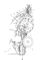
図1は本発明の移植機を適用した乗用田植機の側面図である。乗用田植機は、前後輪1,2を備えた走行機体3の後方に、苗載せ台5を有する植付作業機4が昇降リンク6を介して昇降自在に連結された構造となっている。植付作業機4は、下部に、苗載せ台5から苗を掻き取って圃場に植付ける複数の植付部7と、圃場を均す前後方向の複数のフロート8とを備えている。   FIG. 1 is a side view of a riding rice transplanter to which the transplanter of the present invention is applied. The riding rice transplanter has a structure in which a planting work machine 4 having a seedling table 5 is connected to a rear part of a traveling machine body 3 having front and rear wheels 1 and 2 via a lifting link 6 so as to be movable up and down. The planting work machine 4 is provided with a plurality of planting units 7 for scraping seedlings from the seedling mount 5 and planting them on a farm field, and a plurality of floats 8 in the front-rear direction for leveling the farm field.

上記昇降リンク6には左右方向の横フレーム11がローリング自在に連結されている。該横フレーム11は、左右両端部に上方に向かって延びる縦方向の縦フレーム9,9がそれぞれ設けられている他、上記植付部7が後方に向かって突設されている。   A horizontal frame 11 in the left-right direction is connected to the elevating link 6 in a freely rolling manner. The horizontal frame 11 is provided with vertical frames 9 and 9 extending upward at the left and right end portions, respectively, and the planting portion 7 is projected rearward.

また、植付部7の前方且つ後輪2の後方には、本乗用田植機の略横幅全体にわたって、横方向の整地ロータ12がロータ軸13によって回転駆動自在に軸支されている。整地ロータ12は、左右方向に複数並べて配置されており、整地ロータ12間には後述する水掻きロータ14が設けられている。   Further, in the front of the planting part 7 and behind the rear wheel 2, a horizontal leveling rotor 12 is rotatably supported by a rotor shaft 13 over a substantially entire width of the riding rice transplanter. A plurality of leveling rotors 12 are arranged side by side in the left-right direction, and a wetting rotor 14 described later is provided between the leveling rotors 12.

植付作業時の機体旋回等により荒れた代掻き後の圃場の枕地等において、上記整地ロータ12を接地させて回転駆動させることにより、該枕地等の整地を行うことができる。そして、前記整地ロータ12が植付作業機4の前方に配置されているため、本乗用田植機は、整地ロータ12による整地後の枕地等に苗を植え付けることができる。   In the headland or the like of the field after scraping, which has been rough due to the turning of the body during planting work, etc., the ground leveling rotor 12 can be grounded and rotated to drive the headland or the like. And since the said leveling rotor 12 is arrange | positioned ahead of the planting work machine 4, this riding rice transplanter can plant a seedling in the headland etc. after leveling by the leveling rotor 12. FIG.

次に上記整地ロータ13の支持構造について説明する。
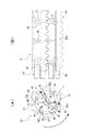
図2は(A)は植付作業機の要部背面図であり、(B)は植付作業機の要部平面図である。図1,図2に示されるように、整地ロータ12の上方には、左右方向の軸16が設けられている。該軸16は、左右の縦フレーム9,9上部に回動自在に支持されており、軸16の左右両端にはそれぞれ軸16と一体回動するアーム17の基端部が一体的に取付けられている。
Next, the support structure for the leveling rotor 13 will be described.
2A is a rear view of the main part of the planting work machine, and FIG. 2B is a plan view of the main part of the planting work machine. As shown in FIGS. 1 and 2, a horizontal axis 16 is provided above the leveling rotor 12. The shaft 16 is rotatably supported on the left and right vertical frames 9, 9, and a base end portion of an arm 17 that rotates integrally with the shaft 16 is integrally attached to the left and right ends of the shaft 16. ing.

各アーム17の先端部にはリンク機構18を介して支持ロッド19の上端部が連結されており、該左右の支持ロッド19,19の下端部には前述したロータ軸13が回転自在に支持されている。そして、上記軸16にはレバー21が設けられており、レバー21を揺動させることによって該軸16を回動させ、ロータ軸13の昇降、すなわち整地ロータ12の昇降操作を行う。レバー21は複数個所に固定可能に構成されており、それに対応して、整地ロータ12が所定の昇降高さで位置決めされる。   An upper end portion of a support rod 19 is connected to the distal end portion of each arm 17 via a link mechanism 18, and the rotor shaft 13 is rotatably supported on the lower end portions of the left and right support rods 19, 19. ing. The shaft 16 is provided with a lever 21. The shaft 16 is rotated by swinging the lever 21, and the rotor shaft 13 is moved up and down, that is, the leveling rotor 12 is moved up and down. The lever 21 is configured to be fixed at a plurality of locations, and the leveling rotor 12 is positioned at a predetermined elevation height correspondingly.

次に整地ロータ12への動力伝動機構について説明する。
図1,2に示すように、上記ロータ軸13の中間部分にはギヤケース22が設けられる一方、走行機体3の後端部下側には整地ロータ12駆動用の駆動ケース23が設けられている。そして、駆動ケース23は、2つのユニバーサルジョイント24,24及び駆動軸26を介して、ギヤケース22に連結されている。上記構成により、駆動ケース23内に設けられたクラッチ(図示しない)を入り操作すると、ギヤケース22に動力が伝動され、ロータ軸13(整地ロータ12)が回動駆動される。
Next, a power transmission mechanism for the leveling rotor 12 will be described.
As shown in FIGS. 1 and 2, a gear case 22 is provided at an intermediate portion of the rotor shaft 13, and a drive case 23 for driving the leveling rotor 12 is provided below the rear end portion of the traveling machine body 3. The drive case 23 is connected to the gear case 22 via two universal joints 24 and 24 and a drive shaft 26. With the above configuration, when a clutch (not shown) provided in the drive case 23 is engaged and operated, power is transmitted to the gear case 22 and the rotor shaft 13 (leveling rotor 12) is rotationally driven.

なお、整地ロータ12によって圃場を整地するのは植付作業機を行う機体前進時であり、機体前進時において整地ロータ12は、車輪1,2と同一方向、すなわち左側面視で反時計回り(図1における矢印方向)に回転駆動される(正転方向に回動駆動される)。   It is to be noted that the ground leveling by the leveling rotor 12 is performed when the machine moves forward with the planting work machine, and when the machine moves forward, the leveling rotor 12 rotates counterclockwise in the same direction as the wheels 1 and 2, that is, when viewed from the left side ( It is rotationally driven in the direction of the arrow in FIG. 1 (rotated in the forward direction).

次に上記整地ロータ12及び水掻きロータ14の構成について説明する。
図2に示すように、上記整地ロータ14は、左右の支持ロッド19,19の外側と、左側の支持ロッド19とギヤケース22の間と、ギヤケース22と右側の支持ロッド19の間との計4箇所に取り付けられ、各整地ロータ12の上方は横方向のカバーにより略全体が覆われている。該カバー27は、左右の支持ロッド19,19によって支持され、カバー27の左右端にはそれぞれ下方及び前方に向かって延びて後輪2にまで至る規制板28,28が一体的に延設されている。
Next, the structure of the leveling rotor 12 and the watering rotor 14 will be described.
As shown in FIG. 2, the leveling rotor 14 includes a total of 4 outsides of the left and right support rods 19, between the left support rod 19 and the gear case 22, and between the gear case 22 and the right support rod 19. The top of each leveling rotor 12 is substantially entirely covered with a horizontal cover. The cover 27 is supported by left and right support rods 19 and 19, and restriction plates 28 and 28 that extend downward and forward and reach the rear wheel 2 are integrally extended at the left and right ends of the cover 27, respectively. ing.

左側の支持ロッド19の外側(左側)に設けられた整地ロータ12と、左側の支持ロッド19とギヤケース22の間に設けられた整地ロータとにより形成される隙間により、整地ロータ12前方の圃場内の泥水を整地ロータ12後方に導く泥水流路Sが構成される。その他、泥水流路Sは、左側の支持ロッド19とギヤケース22の間に設けられた整地ロータ12と、ギヤケース22と右側の支持ロッド19の間に設けられた整地ロータ12とにより形成される隙間によっても構成され、ギヤケース22と右側の支持ロッド19の間に設けられた整地ロータ12と、右側の支持ロッド19の外側(右側)に設けられた整地ロータ12とにより形成される隙間とによっても構成される。以上、計3箇所に形成された泥水流路Sを通って、整地ロータ12前方の泥水が整地ロータ12後方に送られる。   In the field in front of the leveling rotor 12 by a gap formed by the leveling rotor 12 provided on the outside (left side) of the left support rod 19 and the leveling rotor provided between the left support rod 19 and the gear case 22. The muddy water flow path S for guiding the muddy water to the rear of the leveling rotor 12 is configured. In addition, the muddy water flow path S is a gap formed by the leveling rotor 12 provided between the left support rod 19 and the gear case 22 and the leveling rotor 12 provided between the gear case 22 and the right support rod 19. And the clearance formed by the leveling rotor 12 provided between the gear case 22 and the right support rod 19 and the leveling rotor 12 provided outside the right support rod 19 (right side). Composed. As described above, the muddy water in front of the leveling rotor 12 is sent to the rear of the leveling rotor 12 through the muddy water flow paths S formed in three places.

泥水流路Sを形成する整地ロータ12の泥水流路S側の側部には、整地ロータ12と一体回転する水掻きロータ14が設けられている。また、ロータ軸13の左右両端部にそれぞれ設けられた整地ロータ12の外側の側部にも1つづつ計2つの水掻ロータ14が取り付けられており、該2つの水掻きロータ14,14の外側側方は、前述の左右の規制版28,28によって略全体が覆われている。   A draining rotor 14 that rotates integrally with the leveling rotor 12 is provided on the side of the leveling rotor 12 that forms the muddy water path S on the side of the muddy water path S. Also, a total of two scraping rotors 14 are attached to the outer side portions of the leveling rotor 12 respectively provided at the left and right ends of the rotor shaft 13, and the outer sides of the two scraping rotors 14, 14. The side is substantially entirely covered with the left and right restriction plates 28, 28 described above.

上記規制板28、泥水流路S及び水掻きロータ14の作用について説明すると、規制板28によって横方向への流れが規制された整理ロータ12前方の泥水は、泥水流路S内に流れ込む。泥水流路Sに流れ込んだ泥水は上記水掻きロータ14によって効率よく整地ロータ12後方に送り出される。上記一連の作用によって相乗的な効果を相し、整地ロータ12前方の泥水を効率良く整地ロータ12後方に送ることが可能になる。   The operation of the restriction plate 28, the muddy water flow path S and the water scraping rotor 14 will be described. The muddy water in front of the arranging rotor 12 whose flow in the lateral direction is restricted by the restriction plate 28 flows into the muddy water flow path S. The muddy water that has flowed into the muddy water flow path S is efficiently sent to the rear of the leveling rotor 12 by the water scraping rotor 14. Synergistic effects are combined by the above series of actions, and the muddy water in front of the leveling rotor 12 can be efficiently sent to the rear of the leveling rotor 12.

また、3つの泥水流路Sの後方には、前述のフロート8がそれぞれ配置されており、整地ロータ12によって掻き均されていない箇所をフロート8によって均す。なお、29は、植付部7による苗の植付箇所を示し、各フロート8の後方に位置している。各植付箇所29は、左右の両端箇所を除いて概ね各整地ロータ12及び各フロート8によって整地される。左右の両端の植付箇所29,29は、車輪1,2等によって圃場面が荒らされることが少ないため、整地ロータ12やフロート8によって整地しなくても十分に良好な状態が保たれている。   Further, the above-described floats 8 are respectively disposed behind the three muddy water channels S, and the portions that are not scraped by the leveling rotor 12 are leveled by the floats 8. In addition, 29 shows the planting location of the seedling by the planting part 7, and is located behind each float 8. FIG. Each planting location 29 is leveled by each leveling rotor 12 and each float 8 except for the left and right ends. The planting places 29 and 29 at the left and right ends are rarely damaged by the wheels 1 and 2 and the like, so that a sufficiently good state is maintained even if the ground leveling rotor 12 and the float 8 are not leveled. .

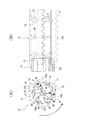
図3(A),(B)は、水掻きロータを取り付けた整地ロータの左側面図及び正面図である。整地ロータ12は、ロータ軸13を挟んで対称に2分割されており、2つの分割片31の組み合わせによって構成され、全体として側面視略正多角形(本実施例では略正6角形)となる篭型をなしている。各分割片31は回転に伴って圃場面を掻く複数の板状の整地部材32と、該整地部材32を左右両側において連結する連結部材33と、整地部材32を左右の略中央において連結する補強部材34とから構成されており、樹脂によって一体成形されている。   FIGS. 3A and 3B are a left side view and a front view of a leveling rotor to which a watering rotor is attached. The leveling rotor 12 is symmetrically divided into two with the rotor shaft 13 in between, and is composed of a combination of two divided pieces 31 and has a substantially regular polygon (substantially regular hexagonal in this embodiment) in side view as a whole. Has a saddle shape. Each of the divided pieces 31 has a plurality of plate-shaped leveling members 32 that scratch the field scene as it rotates, a connecting member 33 that connects the leveling members 32 on both the left and right sides, and a reinforcement that connects the leveling members 32 at the approximate left and right sides. It is comprised from the member 34, and is integrally molded with resin.

連結部材33のロータ軸13を挟んだ両側には、2つの分割片31,31を固定するボルト(図示しない)を取り付けるためのボルト座36と、ナット(図示しない)を収容するためのナット孔37が形成されている。そして、一方の分割片31のボルト座36と他方の分割片31のナット孔37とが対向するように、両分割片31,31をロータ軸13を挟んで対称にボルト及びナットによって一体固定することによって、整地用ロータ12が形成される。   On both sides of the connecting member 33 across the rotor shaft 13, a bolt seat 36 for attaching a bolt (not shown) for fixing the two divided pieces 31, 31 and a nut hole for accommodating a nut (not shown). 37 is formed. Then, both the split pieces 31 and 31 are symmetrically fixed integrally with bolts and nuts with the rotor shaft 13 interposed therebetween so that the bolt seat 36 of one split piece 31 and the nut hole 37 of the other split piece 31 face each other. Thus, the leveling rotor 12 is formed.

また、各連結部材33にはロータ軸13を挿通させる半円状の切欠部38が形成されており、両連結部材33,33を連結することによって、両切欠部38,38が側面視略円形の挿通孔39を形成する。この挿通孔39にロータ軸13を挿通させ、ピン(図示しない)等を用いて整地ロータ12をロータ軸13に固定する。   Each connecting member 33 is formed with a semicircular cutout 38 through which the rotor shaft 13 is inserted. By connecting the two connecting members 33 and 33, the cutouts 38 and 38 are substantially circular in a side view. The insertion hole 39 is formed. The rotor shaft 13 is inserted into the insertion hole 39, and the leveling rotor 12 is fixed to the rotor shaft 13 using a pin (not shown) or the like.

なお、各分割片31には整地部材32が3つ取り付けられており、分割片31が整地ロータ13として組み立てられると、各整地部材32が側面視において正6角形の各頂点部分(多角形の各頂点部分)に位置する。各整地部材32は、波状に成形された端部が連結部材の外側に突出しており、整理ロータ12の回転周面に対して外方を向いた側の面が圃場での整理ロータ12回転時に圃場に接地して圃場を均す作用面32aを形成している。そして、整理部材32及び整地部材32の作業面32aは、整地ロータ12の正転方向後部から回転軸心までの距離Rよりも整地ロータ12の正転方向前部から回転軸心までの距離Rの方が短くなるように構成されている。 In addition, three leveling members 32 are attached to each divided piece 31. When the divided pieces 31 are assembled as the leveling rotor 13, each leveling member 32 has a regular hexagonal apex portion (polygonal shape) in side view. Located at each vertex). Each leveling member 32 has an end formed in a wave shape protruding outside the connecting member, and the surface facing outward with respect to the rotational circumferential surface of the organizing rotor 12 is when the organizing rotor 12 rotates in the field. An action surface 32a for grounding the field and leveling the field is formed. The working surface 32a of the organizing member 32 and the leveling member 32, the distance than the distance R 1 from the forward direction the rear of leveling rotor 12 to the rotational axis from the normal direction front portion of the ground leveling rotor 12 to the rotational axis R 2 is configured to be shorter.

水掻きロータ14は、図3に示すように、ロータ軸13を挟んで対称に2分割されており、2つの分割片41,41の組み合わせによって構成されている。各分割片41は、回転に伴って圃場の泥水を掻き送る板状の3つの水掻き42と、各水掻き42が突設される板状のベース部43とから構成されている。   As shown in FIG. 3, the water draining rotor 14 is divided into two symmetrically across the rotor shaft 13, and is configured by a combination of two divided pieces 41 and 41. Each divided piece 41 is composed of three plate-shaped water scrapers 42 that scrape off the muddy water in the field as it rotates, and a plate-shaped base portion 43 on which each water scraper 42 projects.

水掻きロータ14の分割片41のベース部43は、上記整地ロータ12の分割片31の側面に全体が収まる大きさに形成されており、ベース部43の2箇所に設けられたボルト孔44を介して、連結部材33の側面に取付面全体が接した状態で、ボルト固定される。水掻きロータ14の分割片41を取付固定した状態で、整地ロータ12の分割片31をロータ軸13を挟んで一体固定して整地ロータ12を構成すると、水掻きロータ14の分割片もロータ軸13を挟んで一体固定され、1つの水掻きロータを構成する。   The base portion 43 of the split piece 41 of the water scraping rotor 14 is formed in a size that fits entirely on the side surface of the split piece 31 of the leveling rotor 12, and the bolt holes 44 provided at two locations of the base portion 43 are interposed. Then, the bolt is fixed in a state where the entire mounting surface is in contact with the side surface of the connecting member 33. When the split piece 31 of the leveling rotor 12 is integrally fixed with the rotor shaft 13 sandwiched between the divided pieces 41 of the scooping rotor 14 and fixed, the leveling rotor 12 is configured to fix the rotor shaft 13. It is fixed integrally by sandwiching it and constitutes one scooping rotor.

すなわち、水掻きロータ13の2つ分割片41,41は、整地ロータ12の2つ分割片31,31を一体固定することにより一体になるように構成されている。このことにより、整地ロータ12の分割片31同士の固定を解除する際に、水掻きロータ14の分割片41を取外す必要がなくなり、メンテナンス性等が向上する。   That is, the two divided pieces 41 and 41 of the water scraping rotor 13 are configured to be integrated by fixing the two divided pieces 31 and 31 of the leveling rotor 12 together. This eliminates the need to remove the split piece 41 of the water scraping rotor 14 when releasing the fixing of the split pieces 31 of the leveling rotor 12, and improves maintainability and the like.

整地ロータ12に取付固定されて水掻きロータ14を構成する2つの分割片41,41のベース部43は、側面視において整地ロータ12の前述した挿通孔39と略同一軸心となる略円形のリング状をなし、ベース部43のボルト孔44が90°間隔で配置されている。整地ロータ12への取付状態において水掻きロータ14の2つベース41,41がリング状をなすため、整地ロータ12の挿通孔39が水掻きロータ14によって塞がれることがない。このため、水掻きロータ14を取り付けた状態でも、整地ロータ12に対して、ロータ軸13を挿脱することが可能になる。   The base portions 43 of the two divided pieces 41 and 41 that are attached and fixed to the leveling rotor 12 and constitute the scooping rotor 14 are substantially circular rings that have substantially the same axial center as the aforementioned insertion hole 39 of the leveling rotor 12 in a side view. The bolt holes 44 of the base portion 43 are arranged at intervals of 90 °. Since the two bases 41, 41 of the water scraping rotor 14 form a ring shape when attached to the leveling rotor 12, the insertion hole 39 of the leveling rotor 12 is not blocked by the water scraping rotor 14. For this reason, it is possible to insert / remove the rotor shaft 13 with respect to the leveling rotor 12 even in the state where the water scraping rotor 14 is attached.

水掻き42は、ベース部43からロータ軸13の軸方向に突設されるプレート状の部材であり、1つのベース部43に等間隔で3つ設けられており、水掻きロータ14が整地ロータ12に取付固定された状態で、整地ロータ12の側方から突出した状態になる。各水掻き42は、水掻きロータ14の回転周面に対して内方を向いた側の面が圃場での水掻きロータ14回転時に圃場の泥水を送り出す作用面42aを形成している。そして、水掻き42及び水掻き42の作業面42aは、水掻きロータ14の正転方向(整地ロータの正転方向)後部から回転軸心までの距離rよりも水掻きロータ14の正転方向前部から回転軸心までの距離rの方が長くなるように、正転方向側に湾曲形成されている。 The webbing 42 is a plate-like member protruding from the base part 43 in the axial direction of the rotor shaft 13, and three bases 43 are provided at equal intervals on the base part 43. In a state of being attached and fixed, the state is a state of protruding from the side of the leveling rotor 12. In each of the webs 42, the surface facing inward with respect to the rotational circumferential surface of the web rotor 14 forms an action surface 42a for sending muddy water in the field when the web rotor 14 rotates in the field. The working surface 42a of the paddle 42 and paddle 42, the forward direction the front of the paddle rotor 14 than the distance r 1 from the rear (forward direction of the ground leveling rotor) forward direction of the paddle rotor 14 to the rotational axis as towards the distance r 2 to the rotation axis becomes longer, which is curved in the forward direction.

上記構成の水掻きロータ14は、水掻き42の基端部(図3(B)における右端部)のみを支持し、先端部を支持しない片持ち構造であることから、水掻きの先端部からベース部43のボルト孔44に容易にアクセスすることができるため、組み付けを容易に行うことができる。   Since the water scraping rotor 14 having the above-described structure has a cantilever structure that supports only the base end portion (the right end portion in FIG. 3B) of the water scraping 42 and does not support the front end portion, the base portion 43 extends from the front end portion of the water scraping. Since the bolt hole 44 can be easily accessed, the assembly can be easily performed.

以上、水掻きロータ14の各分割片41に3つの水掻き42を等間隔で設ける例につき説明したが、図4は、水掻きロータ14の各分割片41に6つの水掻き42を等間隔で設ける例につき示している。上記構成の水掻きロータ14によれば、泥水流路Sにおいて泥水を後方に送る効率がさらに上昇する。   As described above, the example in which the three scrapers 42 are provided at equal intervals on each divided piece 41 of the water scraping rotor 14 has been described. FIG. 4 is an example in which the six scrapers 42 are provided at equal intervals on each divided piece 41 of the water scraping rotor 14. Show. According to the water scraping rotor 14 having the above-described configuration, the efficiency of sending muddy water backward in the muddy water flow path S further increases.

本発明の移植機を適用した乗用田植機の側面図である。It is a side view of the riding rice transplanter to which the transplanter of the present invention is applied. (A)は植付作業機の要部背面図であり、(B)は植付作業機の要部平面図である。(A) is a principal part rear view of a planting work machine, (B) is a principal part top view of a planting machine. (A),(B)は、水掻きロータを取り付けた整地ロータの左側面図及び正面図である。(A), (B) is the left view and front view of the leveling rotor which attached the watering rotor. 他の実施例を示す水掻きロータを取り付けた整地ロータの図面であり、(A),(B)は、水掻きロータを取り付けた整地ロータの左側面図及び正面図である。It is drawing of the leveling rotor which attached the watering rotor which shows another Example, (A), (B) is the left view and front view of the leveling rotor which attached the watering rotor.

符号の説明Explanation of symbols

3 走行機体
4 植付作業機
12 整地ロータ
14 水掻きロータ
28 規制板
32 整地部材
32a 作用面
42 水掻き
42a 作用面
S 泥水流路
DESCRIPTION OF SYMBOLS 3 Traveling machine body 4 Planting work machine 12 Leveling rotor 14 Water scraping rotor 28 Control board 32 Leveling member 32a Action surface 42 Water scraping 42a Action surface S Mud flow path

Claims (3)

苗の植付けを行う植付作業機(4)を走行機体(3)の後方に連結し、圃場を掻き均す整地ロータ(12)を横方向に複数並べて植付作業機(4)の前方に配置し、整地ロータ(12)間に圃場内の泥水を後方に導く泥水流路(S)を形成した移植機において、機体前進走行にともなって泥水を後方に送る方向に回転する水掻きロータ(14)を、前記泥水流路(S)に設けた移植機。   A planting work machine (4) for planting seedlings is connected to the rear of the traveling machine body (3), and a plurality of leveling rotors (12) for leveling the field are arranged in the lateral direction in front of the planting work machine (4). In a transplanter having a muddy flow path (S) that is disposed and guides muddy water in a farm field rearward between the leveling rotors (12), a water scraping rotor (14) that rotates in a direction to send muddy water backward as the aircraft moves forward ) In the muddy water flow path (S). 水掻きロータ(14)は回転周面に複数の水掻き(42)を有し、該水掻き(42)の作用面(42a)を、機体前進走行に伴う水掻きロータ(14)の回転方向前側位置になる従って水掻きロータ(14)の回転軸心から遠ざかるように構成し、整地ロータ(12)は回転周面に複数の整地部材(32)を有し、該整地部材(32)の作用面(32a)を、機体前進走行に伴う整地ロータ(12)の回転方向前側位置になるに従って整地ロータ(12)の回転軸心に近づくように構成した請求項1の移植機。   The water scraping rotor (14) has a plurality of water scoops (42) on the rotating peripheral surface, and the action surface (42a) of the water scissors (42) is positioned at the front side in the rotational direction of the water scraping rotor (14) accompanying forward traveling of the machine body. Therefore, it is constructed so as to move away from the rotation axis of the water draining rotor (14), and the leveling rotor (12) has a plurality of leveling members (32) on the rotating peripheral surface, and the working surface (32a) of the leveling member (32). The transplanter according to claim 1, wherein the machine is configured so as to approach the rotational axis of the leveling rotor (12) as the position of the leveling rotor (12) increases as the position of the leveling rotor (12) increases. 水掻きロータ(14)の側方に、泥水の横方向への流れを規制する規制板(28)を設けた請求項1又は2の移植機。   The transplanter according to claim 1 or 2, wherein a regulating plate (28) for regulating the lateral flow of muddy water is provided on a side of the watering rotor (14).
JP2007073559A 2007-03-20 2007-03-20 Transplanter Pending JP2008228663A (en)

Priority Applications (1)

Application Number Priority Date Filing Date Title
JP2007073559A JP2008228663A (en) 2007-03-20 2007-03-20 Transplanter

Applications Claiming Priority (1)

Application Number Priority Date Filing Date Title
JP2007073559A JP2008228663A (en) 2007-03-20 2007-03-20 Transplanter

Publications (1)

Publication Number Publication Date
JP2008228663A true JP2008228663A (en) 2008-10-02

Family

ID=39902232

Family Applications (1)

Application Number Title Priority Date Filing Date
JP2007073559A Pending JP2008228663A (en) 2007-03-20 2007-03-20 Transplanter

Country Status (1)

Country Link
JP (1) JP2008228663A (en)

Cited By (1)

* Cited by examiner, † Cited by third party
Publication number Priority date Publication date Assignee Title
JP2018191616A (en) * 2017-05-20 2018-12-06 みのる産業株式会社 Sludge guide plate in work machine for paddy field

Cited By (1)

* Cited by examiner, † Cited by third party
Publication number Priority date Publication date Assignee Title
JP2018191616A (en) * 2017-05-20 2018-12-06 みのる産業株式会社 Sludge guide plate in work machine for paddy field

Similar Documents

Publication Publication Date Title
JP2008228663A (en) Transplanter
JP2007312661A (en) Transplanter
JP2008228601A (en) Rice transplanter
JP2007202494A (en) Transplanter
JP5718739B2 (en) Paddy field machine leveling equipment
KR200489965Y1 (en) Rigding Device for Tractor
JPH1056835A (en) Transplanter with simultaneous puddling function
CA2776762C (en) Ditch forming implement
KR101897671B1 (en) Rotavator having integrated harrow
JP2007267642A (en) Rice transplanter
JP2010046029A (en) Transplanter
JP2009022181A (en) Transplanter
JP7290333B2 (en) Puddling machine
JP6579606B2 (en) Pricking machine
JP5781912B2 (en) Rice transplanter
JPH09294406A (en) Transplanting machine
JP2009159919A (en) Transplanter
JP7220919B2 (en) Puddling machine
JP2003102219A (en) Transplanter
JP2007104935A (en) Transplanting machine
JP4011447B2 (en) Rotor for leveling of transplanting machine
JP3811638B2 (en) Wave extinguishing device for paddy field machine
JPH09224427A (en) Walking type non-tilled planting machine
JP3983946B2 (en) Transplanter
JP4799963B2 (en) Transplanter