JP2008215367A - Joint structure of vehicle body plate material for vehicle - Google Patents
Joint structure of vehicle body plate material for vehicle Download PDFInfo
- Publication number
- JP2008215367A JP2008215367A JP2007049240A JP2007049240A JP2008215367A JP 2008215367 A JP2008215367 A JP 2008215367A JP 2007049240 A JP2007049240 A JP 2007049240A JP 2007049240 A JP2007049240 A JP 2007049240A JP 2008215367 A JP2008215367 A JP 2008215367A
- Authority
- JP
- Japan
- Prior art keywords
- body plate
- bonding
- vehicle body
- adhesive
- edge
- Prior art date
- Legal status (The legal status is an assumption and is not a legal conclusion. Google has not performed a legal analysis and makes no representation as to the accuracy of the status listed.)
- Granted
Links
Images


Abstract
Description
本発明は、2つの車体板材の接合面同士を接着剤で接着接合したのち、それらの接合面の複数箇所を間隔をあけて、溶接、リベットなどの加圧圧着接合手段により圧着接合してなる車両の車体板材の接合構造に関する。 In the present invention, the joint surfaces of two vehicle body plate members are adhesively bonded to each other with an adhesive, and then a plurality of portions of the joint surfaces are spaced and joined by pressure-bonding means such as welding and rivets. The present invention relates to a joining structure for vehicle body plate materials.
従来、自動車用の車体を構成する2つの車体板材を接合するのに、その接合強度を高めるために、2つの車体板材を予め接着剤により接着接合してから、それらを溶接、リベットなどの加圧圧着接合手段により圧着接合するようにした技術手段が既に知られている。 Conventionally, in order to join two body plate members constituting an automobile body, in order to increase the joint strength, the two body plate members are bonded and bonded together with an adhesive in advance, and then they are welded, added with rivets or the like. There is already known a technical means in which pressure bonding is performed by a pressure bonding means.
しかしながら、従来の技術手段では、図6に示すように、2つの車体板材(たとえばフロントサイドフレームとフロアパネル)を接着接合した後に加圧圧着接合したとき、接着剤を2つの車体板材の接合面のエッジ部まで行き渡らせるのが難しく、接着部の剛性、強度が低下し、またエッジ部の角部の接着面に隙間が生じてしまい、電着塗料が剥離し、特に、2つの車体板材を鉄板とアルミ板など異種金属板で構成した場合には、それらの直接接触により電食してしまうという不都合があった。そこで、このような不都合を解消すべく、接着剤を増量すれば、接着剤が車体板材の間からはみだすことがあり、はみだした接着剤がリベットの打込みダイスの凹部などに入り込んで接合品質に悪影響を与えるとう弊害があった。 However, in the conventional technical means, as shown in FIG. 6, when two body plate members (for example, a front side frame and a floor panel) are bonded and bonded together by pressure and pressure bonding, the adhesive is bonded to the two vehicle body plate members. It is difficult to spread to the edge part, the rigidity and strength of the adhesive part are reduced, and a gap is formed in the adhesive surface of the corner part of the edge part, and the electrodeposition paint is peeled off. In the case of using different metal plates such as an iron plate and an aluminum plate, there is an inconvenience that galvanic corrosion occurs due to their direct contact. Therefore, if the amount of the adhesive is increased in order to eliminate such inconvenience, the adhesive may protrude from between the vehicle body plate materials, and the protruding adhesive will enter into the recesses of the rivet driving die and adversely affect the bonding quality. There was a harmful effect of giving.
そこで、後記特許文献1に開示のものでは、異種の金属板よりなる車体板材を接合する接合部に2種の接着剤を使用し、すなわちリベットで加圧されるエリアの接着剤を他のエリアに配置される接着剤よりも相対的に流動性の低い接着剤を使用するようにして前記弊害を解消するよにした技術手段も既に提案されている。
ところが、前記特許文献1に開示されるものでは、2種の接着剤を使用するので、接着剤の塗布作業が煩雑であり、コスト高を招くばかりでなく、接合面の全域に接着剤を均等に行き渡らせることが難しいという問題がある。 However, in the one disclosed in Patent Document 1, since two types of adhesives are used, the operation of applying the adhesive is complicated, and not only the cost is increased, but the adhesive is evenly distributed over the entire joining surface. There is a problem that it is difficult to spread.
本発明はかかる実情に鑑みてなされたものであり、接着剤による接着接合と、リベット、溶接などの加圧圧着接合とを併用した、2つの車体板材の接合構造において、接着剤による接着強度を高めると共に接着剤による接合品質を向上させるようにすることを目的とする。 The present invention has been made in view of such a situation, and in the joint structure of two vehicle body plate materials, which uses both adhesive bonding by an adhesive and pressure-bonding bonding such as rivets and welding, the adhesive strength by the adhesive is increased. It aims at improving and joining quality by an adhesive agent while improving.
上記目的を達成するため、請求項1記載の発明は、2つの車体板材の接合面同士を接着剤で接着接合したのち、それらの接合面の複数箇所を間隔をあけて、溶接、リベットなどの加圧圧着接合手段により圧着接合してなる車両の車体板材の接合構造において、
一方の車体板材の接合面の、圧着接合打点の配列方向端面のエッジ部の形状を、その圧着接合打点を中心とする半径のアール形状に形成したことを特徴としている。
In order to achieve the above-mentioned object, the invention according to claim 1 is characterized in that after joining the joint surfaces of the two body plate materials with an adhesive, a plurality of locations of the joint surfaces are spaced apart, and welding, rivets, etc. In the joining structure of the vehicle body plate material of the vehicle formed by pressure bonding by the pressure pressure bonding means,
The feature is that the shape of the edge portion of the joining surface of one of the body plate members at the end face in the arrangement direction of the crimping joint hit points is formed into a rounded shape having a radius centering on the crimping joint hitting point.
また上記目的を達成するため、請求項1記載の発明は、請求項1記載のものにおいて、 2つの車体板材の少なくとも一方は、底板部とその底板部の両側より起立する縦壁部と、その縦壁部の上縁より外向きに横方向に延びるフランジ部を備えて横断面チャンネル状に形成され、前記フランジ部は、他方の車体板材との接合面を有し、該接合面は、縦壁部との接続側のエッジ部および自由端側のエッジ部をいずれも前記アール形状に形成したことを特徴としている。 In order to achieve the above object, the invention described in claim 1 is the one described in claim 1, wherein at least one of the two body plate members includes a bottom plate portion and a vertical wall portion standing up from both sides of the bottom plate portion, A flange portion extending laterally outwardly from the upper edge of the vertical wall portion is formed in a cross-sectional channel shape, and the flange portion has a joint surface with the other body plate material, and the joint surface is The edge part on the connection side with the wall part and the edge part on the free end side are both formed in the rounded shape.
本請求項各項記載の発明によれば、2つの車両用車体板材を、接着剤により接着接合したのち溶接、リベットなどで加圧圧着接合するものにおいて、接着面に接着剤を均等に行き渡らせることができ、接着部の剛性、強度を確保することができ、また、特に、2つの車体板材が異種材料によりなる場合に、それらの電食を防止することができる。 According to the invention described in the claims, in the case where two vehicle body plate members are bonded and bonded by an adhesive, and then pressure-bonded by welding, rivets or the like, the adhesive is evenly distributed on the bonding surface. In addition, the rigidity and strength of the bonded portion can be secured, and in particular, when the two vehicle body plate materials are made of different materials, their electrolytic corrosion can be prevented.
以下、本発明の実施の形態を、添付図面に示した本発明の実施例に基づいて具体的に説明する。 DESCRIPTION OF THE PREFERRED EMBODIMENTS Embodiments of the present invention will be specifically described below based on examples of the present invention shown in the accompanying drawings.
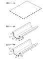
以下の実施例は、本発明車両の2つの車体板材の接合構造を自動車の車体のフロントサイドフレームとフロアパネルとの接合構造に実施した場合であって、図1は、自動車の車体の一部破断の部分斜視図、図2は、図1の図2−2線に沿う拡大断面図、図3は、図1の3矢視拡大図、図4は、図3の4矢視拡大図、図5は、フロントサイドフレームの成形過程を示す図である。
The following embodiment is a case where the joining structure of the two body plate members of the vehicle of the present invention is implemented in the joining structure of the front side frame and the floor panel of the automobile body. FIG. FIG. 2 is an enlarged cross-sectional view taken along line 2-2 of FIG. 1, FIG. 3 is an enlarged view of
図1において、自動車の車体Bの下部には、その前後方向に縦走する左右一対のフロアフレーム1,1が互いに平行に設けられ、これらのフロアフレーム1,1の前部には、左右一対のフロントサイドフレーム2,2の後部が一体に接合されている。左右一対のフロントサイドフレーム2,2は、車室とエンジンルームとを仕切るダッシュボード3を貫通してエンジンルームの下方へと延長され、それらの前部が図示しないバルクヘッドのロアクロスメンバに結合されている。車室内において、左右一対のフロアフレーム1,1およびフロントサイドフレーム2,2の上面には、フロアパネル4が後に述べる接合手段を介して一体に接合される。フロアパネル4の左右中央部には、断面凸状のフロアトンネルスチフナ5が一体に隆起されており、このフロアトンネルスチフナ5は、ダッシュボード3を貫通してエンジンルームの下部へと延長されている。
In FIG. 1, a pair of left and right floor frames 1, 1 that run longitudinally in the front-rear direction are provided in parallel with each other at the lower part of a vehicle body B of the automobile. The rear portions of the
図2,3に示すように、2つの車体板材の一方を構成する左右のフロントサイドフレーム2,2は、左右のフロアフレーム1,1の前部に一体に接合される。各フロントサイドフレーム2は、フロアフレーム1と略同じ形状に形成されており、図2,3に示すように、略水平に延びる底壁部2aと、この底壁部2aの左右両側から起立する左右縦壁部2b,2bと、これらの縦壁部2b,2bの上縁より横方向に外向きに延びる左右フランジ部2c,2cと、左右フランジ部2c,2cより下向きに屈曲する屈曲端部2d,2dを有して横断面チャンネル状に形成されている。そして、左右フランジ部2c,2cの上面が、他の車体板材を構成するフロアパネル4との接合面とされている。
As shown in FIGS. 2 and 3, the left and right
フロントサイドフレーム2は、車体Bの軽量化を図るために、軽合金板製、この実施例ではアルミ合金板製であって、その左右上縁のフランジ部2c,2cの上面には、鋼板製のフロアパネル4が、本発明にかかる接合手段により一体に接合される。すなわち、図3,4に示すように、前記フランジ部2c,2cの上面には、熱硬化性の接着剤7が塗布され、その上にフロアパネル4が接着接合される。その後、フロントサイドフレーム2のフランジ部2c,2cとフロアパネル4との接着部は、フランジ部2c,2cの長手方向に沿い所定の間隔を存して加圧圧着接合、この実施例では、スポット溶接8される。
The
ところで、この実施例のものでは、フロントサイドフレーム2のフランジ部2c,2cの上面には、その全域、特にその端部に至るまで接着剤7が万遍なく均等に行き渡るように、フランジ部2c,2cの前記スポット溶接7の打点P…の配列方向端面のエッジ部が特殊な形状に加工されている。すなわち、図4に最も明の瞭に示すように、フロントサイドフレーム2のフランジ部2cの、縦壁部2bとの接続側における端面のエッジ部E1は、スポット溶接打点Pを中心点とした半径Rのアール形状に形成され、同じくフランジ部2cの自由端側の端面のエッジ部E2もまたスポット溶接打点Pを中心点とした半径Rのアール形状に形成され、この半径Rの長さは、フランジ部2cの幅の約1/2である。以上のように、フランジ部2cのエッジ部E1,E2を前記アール形状に形成することにより、接着剤7の塗布後、その接着剤7はスポット溶接8による加圧圧着を受けてそのスポット溶接打点Pを中心として円状に広がり、フランジ部2c端面のエッジ部E1,E2まで均等に充填させることができる。
By the way, in the thing of this Example, the
なお、接着剤量は、少量の接着剤7がエッジ部E1,E2からはみ出す程度に設定することにより、該エッジ部E1,E2を接着剤7により保護することができ、フロントサイドフレーム2とフロアパネル4同士の直接接触を回避することができ、電食錆の発生を防止できる。
The amount of adhesive is set so that a small amount of the adhesive 7 protrudes from the edge portions E1 and E2, so that the edge portions E1 and E2 can be protected by the adhesive 7, and the
図5(a)〜(c)に示すように、車体板材の一方である、フロントサイドフレーム2は、アルミ合金材よりなる四角なブランク材から、ドロー成形およびトリム成形を経て作られるが、フランジ部2c端面の縦壁部2bとの接続側のエッジ部E1のアール形状は、前記ドロー成形過程で成形され、またフランジ部2c端面の自由端側のエッジ部E2のアール形状はトリム成形過程で成形される。
As shown in FIGS. 5 (a) to 5 (c), the
また、図2に示すように、フロントサイドフレーム1には、フランジ部2cの外縁に屈曲端部2dを形成したことにより、そこにダストシーラ10を塗布した際に、そのダストシーラ10の保持力を高めて、錆に対する耐久性を高めることができる。
Further, as shown in FIG. 2, the front side frame 1 is formed with a
以上のように、この実施例によれば、フロントサイドフレーム2のフランジ部2cのスポット溶接打点P…の配列方向端面の、縦壁部2cとの接続側およびその自由端側のエッジ部E1,Eは何れもスポット溶接8の打点Pを中心とする半径Rのアール形状に形成されるので、スポット溶接8の加圧圧着時に、接着剤7をフランジ部2cのエッジ部E1,E2まで均等に充填させることができ、接着剤7による接着接合部の剛性、強度を確保することができ、接合部のエッジ部の確実な保護が可能となり、電食による錆びの発生を防止することができる。
As described above, according to this embodiment, the edge portions E1 on the connection side with the
以上、本発明の実施例について説明したが、本発明はその実施例に限定されることなく、本発明の範囲内で種々の実施例が可能である。 As mentioned above, although the Example of this invention was described, this invention is not limited to the Example, A various Example is possible within the scope of the present invention.
たとえば、この実施例では、本発明車体板材の接合構造をフロントサイドフレーム2とフロアパネル4との接合構造に実施した場合を説明したが、これを他の車体板材の接合構造、たとえば、フロアフレームとフロントサイドフレームとの接合構造にも実施でき、また、この実施例では、加圧圧着接合としてスポット溶接を用いた場合を説明したが、これに代えてセルフピアスリベットなど他の加圧圧着接合を用いてもよい。
For example, in this embodiment, the case where the joining structure of the vehicle body plate material of the present invention is implemented in the joining structure of the
2・・・・・・・・・車体板材(フロントサイドフレーム)
2a・・・・・・・・底壁部
2b・・・・・・・・縦壁部
2c・・・・・・・・フランジ部
4・・・・・・・・・車体板材(フロアパネル)
7・・・・・・・・・接着剤
8・・・・・・・・・加圧圧着接手段(スポット溶接)
E1,E2・・・・・エッジ部
P・・・・・・・・・圧着接合打点(スポット溶接打点)
2 .... Body plate material (front side frame)
2a .........
7 ·········
E1, E2 ... Edge part P ... Crimp joint spot (spot weld spot)
Claims (2)
一方の車体板材(2)の接合面の、圧着接合打点(P)の配列方向端面のエッジ部(E1,E2)の形状を、その圧着接合打点(P)を中心とする半径のアール形状に形成したことを特徴とする、車両の車体板材の接合構造。 After the bonding surfaces of the two vehicle body plate members (2, 4) are bonded and bonded together with an adhesive (7), a plurality of portions of the bonding surfaces are spaced apart, and a pressure-bonding bonding means such as welding or rivet (8 ) In the joining structure of the vehicle body plate material,
The shape of the edge part (E1, E2) of the end surface in the arrangement direction of the pressure bonding bonding point (P) of the bonding surface of one of the body plate members (2) is changed to a rounded shape having a radius centered on the pressure bonding bonding point (P). A joint structure for a vehicle body plate material, characterized by being formed.
Priority Applications (1)
| Application Number | Priority Date | Filing Date | Title |
|---|---|---|---|
| JP2007049240A JP4767882B2 (en) | 2007-02-28 | 2007-02-28 | Bonding structure of vehicle body plate material |
Applications Claiming Priority (1)
| Application Number | Priority Date | Filing Date | Title |
|---|---|---|---|
| JP2007049240A JP4767882B2 (en) | 2007-02-28 | 2007-02-28 | Bonding structure of vehicle body plate material |
Publications (2)
| Publication Number | Publication Date |
|---|---|
| JP2008215367A true JP2008215367A (en) | 2008-09-18 |
| JP4767882B2 JP4767882B2 (en) | 2011-09-07 |
Family
ID=39835659
Family Applications (1)
| Application Number | Title | Priority Date | Filing Date |
|---|---|---|---|
| JP2007049240A Expired - Fee Related JP4767882B2 (en) | 2007-02-28 | 2007-02-28 | Bonding structure of vehicle body plate material |
Country Status (1)
| Country | Link |
|---|---|
| JP (1) | JP4767882B2 (en) |
Cited By (8)
| Publication number | Priority date | Publication date | Assignee | Title |
|---|---|---|---|---|
| JP2010132083A (en) * | 2008-12-03 | 2010-06-17 | Honda Motor Co Ltd | Vehicle body structure |
| JP2010132087A (en) * | 2008-12-03 | 2010-06-17 | Honda Motor Co Ltd | Vehicle body structure |
| WO2011157204A1 (en) * | 2010-06-13 | 2011-12-22 | Jia Bingcheng | Vehicle frame component |
| CN104097699A (en) * | 2013-04-02 | 2014-10-15 | 铃木株式会社 | Vehicle front structure |
| JP6447702B1 (en) * | 2017-12-01 | 2019-01-09 | マツダ株式会社 | Vehicle body structure |
| CN109421826A (en) * | 2017-08-24 | 2019-03-05 | 马自达汽车株式会社 | The body construction of vehicle |
| JP6485525B1 (en) * | 2017-12-01 | 2019-03-20 | マツダ株式会社 | Vehicle body structure |
| JP2019098902A (en) * | 2017-12-01 | 2019-06-24 | マツダ株式会社 | Vehicle body structure |
-
2007
- 2007-02-28 JP JP2007049240A patent/JP4767882B2/en not_active Expired - Fee Related
Cited By (12)
| Publication number | Priority date | Publication date | Assignee | Title |
|---|---|---|---|---|
| JP2010132083A (en) * | 2008-12-03 | 2010-06-17 | Honda Motor Co Ltd | Vehicle body structure |
| JP2010132087A (en) * | 2008-12-03 | 2010-06-17 | Honda Motor Co Ltd | Vehicle body structure |
| WO2011157204A1 (en) * | 2010-06-13 | 2011-12-22 | Jia Bingcheng | Vehicle frame component |
| CN104097699A (en) * | 2013-04-02 | 2014-10-15 | 铃木株式会社 | Vehicle front structure |
| CN109421826A (en) * | 2017-08-24 | 2019-03-05 | 马自达汽车株式会社 | The body construction of vehicle |
| JP2019038364A (en) * | 2017-08-24 | 2019-03-14 | マツダ株式会社 | Vehicle body structure for vehicle |
| US10518818B2 (en) | 2017-08-24 | 2019-12-31 | Mazda Motor Corporation | Vehicle body structure of vehicle |
| JP6447702B1 (en) * | 2017-12-01 | 2019-01-09 | マツダ株式会社 | Vehicle body structure |
| JP6485525B1 (en) * | 2017-12-01 | 2019-03-20 | マツダ株式会社 | Vehicle body structure |
| JP2019098902A (en) * | 2017-12-01 | 2019-06-24 | マツダ株式会社 | Vehicle body structure |
| JP2019098897A (en) * | 2017-12-01 | 2019-06-24 | マツダ株式会社 | Vehicle body structure |
| JP2019098901A (en) * | 2017-12-01 | 2019-06-24 | マツダ株式会社 | Vehicle body structure |
Also Published As
| Publication number | Publication date |
|---|---|
| JP4767882B2 (en) | 2011-09-07 |
Similar Documents
| Publication | Publication Date | Title |
|---|---|---|
| JP4767883B2 (en) | Bonding structure of vehicle body plate material | |
| JP4767882B2 (en) | Bonding structure of vehicle body plate material | |
| JP4273922B2 (en) | Body member joint structure | |
| CN108025771B (en) | Vehicle body structure of vehicle | |
| JP6546065B2 (en) | Front body structure | |
| US10046422B2 (en) | Extrusion piece with insert of dissimilar material | |
| US9085327B2 (en) | Vehicle roof reinforcement | |
| US20180134318A1 (en) | Vehicle lower part structure | |
| JP2019099098A (en) | Vehicle member joint structure | |
| US10689035B2 (en) | Side rail and manufacturing method of side rail | |
| JP5754643B2 (en) | Manufacturing method for superstructure of vehicle body | |
| JP2007022262A (en) | Joint structure of panel | |
| JP4523976B2 (en) | Body front structure | |
| JP2006327250A (en) | Roof device for vehicle | |
| JP2006281956A (en) | Sheet metal joint structure for vehicle body | |
| JP4638215B2 (en) | Metal plate joint structure | |
| KR20170081515A (en) | Structure for increasing of stiffness of joint portion ins vehicle | |
| JP2017515746A (en) | Automobile roof brazed to the side of the body shell | |
| JP2015110959A (en) | Joint structure of car body member | |
| JP5853413B2 (en) | Dash panel structure and manufacturing method thereof | |
| JP5659141B2 (en) | Vehicle operation pedal | |
| CN201442607U (en) | Body structure of novel passenger car | |
| JP4588433B2 (en) | Metal plate joint structure | |
| JP5468637B2 (en) | Auto body floor structure | |
| CN110304147B (en) | Vehicle body side structure |
Legal Events
| Date | Code | Title | Description |
|---|---|---|---|
| A621 | Written request for application examination |
Free format text: JAPANESE INTERMEDIATE CODE: A621 Effective date: 20091127 |
|
| A977 | Report on retrieval |
Free format text: JAPANESE INTERMEDIATE CODE: A971007 Effective date: 20110118 |
|
| A131 | Notification of reasons for refusal |
Free format text: JAPANESE INTERMEDIATE CODE: A131 Effective date: 20110330 |
|
| A521 | Written amendment |
Free format text: JAPANESE INTERMEDIATE CODE: A523 Effective date: 20110517 |
|
| TRDD | Decision of grant or rejection written | ||
| A01 | Written decision to grant a patent or to grant a registration (utility model) |
Free format text: JAPANESE INTERMEDIATE CODE: A01 Effective date: 20110608 |
|
| A01 | Written decision to grant a patent or to grant a registration (utility model) |
Free format text: JAPANESE INTERMEDIATE CODE: A01 |
|
| A61 | First payment of annual fees (during grant procedure) |
Free format text: JAPANESE INTERMEDIATE CODE: A61 Effective date: 20110615 |
|
| R150 | Certificate of patent or registration of utility model |
Ref document number: 4767882 Country of ref document: JP Free format text: JAPANESE INTERMEDIATE CODE: R150 Free format text: JAPANESE INTERMEDIATE CODE: R150 |
|
| FPAY | Renewal fee payment (event date is renewal date of database) |
Free format text: PAYMENT UNTIL: 20140624 Year of fee payment: 3 |
|
| LAPS | Cancellation because of no payment of annual fees |