JP2008212707A - Game machine - Google Patents
Game machine Download PDFInfo
- Publication number
- JP2008212707A JP2008212707A JP2008114186A JP2008114186A JP2008212707A JP 2008212707 A JP2008212707 A JP 2008212707A JP 2008114186 A JP2008114186 A JP 2008114186A JP 2008114186 A JP2008114186 A JP 2008114186A JP 2008212707 A JP2008212707 A JP 2008212707A
- Authority
- JP
- Japan
- Prior art keywords
- mounting
- frame
- door frame
- main body
- led
- Prior art date
- Legal status (The legal status is an assumption and is not a legal conclusion. Google has not performed a legal analysis and makes no representation as to the accuracy of the status listed.)
- Granted
Links
Images


Landscapes
- Pinball Game Machines (AREA)
Abstract
Description
本発明は、パチンコ遊技機やスロットマシン等のように個別の機能を備えた複数のパネル体を組み立てて一体化し遊技者に所定の遊技を提供するようにした遊技機に関するものである。 The present invention relates to a gaming machine such as a pachinko gaming machine or a slot machine that assembles and integrates a plurality of panel bodies having individual functions to provide a predetermined game to a player.
遊技機として従来から親しまれているパチンコ遊技機やスロットマシン等は異なる複数のパネル体を組み合わせて製造するようになっている。例えばパチンコ遊技機に必要とされるパネル体としては具体的に扉枠、遊技盤、遊技機本体、機構盤等が挙げられる。要はこれら遊技機では各パネル体毎に機能を分担させこれらを組み合わせることで結果的に遊技機として機能し得るようにしているわけである。これらパネル体は一般に外枠をベースとして前後方向に重ね合わせながら組み立てられ一体化される。ここに各パネル体自体も複数の機能部品を組み合わせて構成されている。そして、機能部品の組み合わせによってパネル体として所定の機能を奏するように構成されている。 Pachinko machines, slot machines, and the like that have been familiar as gaming machines have been manufactured by combining a plurality of different panel bodies. For example, specific examples of the panel body required for the pachinko gaming machine include a door frame, a gaming board, a gaming machine main body, a mechanism board, and the like. The point is that these gaming machines share functions for each panel body and combine them to function as a gaming machine as a result. These panel bodies are generally assembled and integrated while overlapping in the front-rear direction based on an outer frame. Each panel body itself is also configured by combining a plurality of functional parts. And it is comprised so that a predetermined | prescribed function may be show | played as a panel body by the combination of a functional component.
従来では付属的な機能部品、例えばLED基板、中継基板、表示装置等はやはり機能部品としてのプラスチック製ベースに装着され、更に必要な場合には補強のための金属製の薄板状のフレームが固着されてパネル体が構成されるようになっている。 Conventionally, accessory functional parts such as LED boards, relay boards, display devices, etc. are also mounted on plastic bases as functional parts, and if necessary, a metal thin plate frame is attached for reinforcement. Thus, the panel body is configured.
ところで、最近の遊技機では種々の機能を充実させる要請から上記プラスチック製ベースにより多くの機能部品を装着する傾向にある。するとプラスチック製ベースがそれら機能部品の装着による重量や装着用の透孔を形成したりしなければならず、いきおいプラスチック製ベースに十分な強度を保証できなくなってきている。また、同ベースに対する機能部品の配置場所も十分確保できなくなってきている。 By the way, in recent gaming machines, there is a tendency to mount more functional parts on the plastic base in order to satisfy various functions. As a result, the plastic base has to form a weight due to the mounting of these functional parts and a through hole for mounting, and it is no longer possible to guarantee sufficient strength for the plastic base. In addition, it has become impossible to secure a sufficient location for the functional components to be placed on the base.
本発明は、このような従来の技術に存在する問題点に着目してなされたものである。その目的とするところは、機能部品が増加してもその増加によって生ずる諸問題に対応できるパネル体を構成することが可能な遊技機を提供することにある。 The present invention has been made paying attention to such problems existing in the prior art. An object of the present invention is to provide a gaming machine capable of configuring a panel body that can cope with various problems caused by an increase in functional parts.
上記の目的を達成するために、請求項1に記載の発明では、複数の機能部品を組み合わせて一枚のパネル体を構成し、複数の同パネル体を組み立てて一体化するようにした遊技機において、複数の機能部品を同じく機能部品としての金属製ベースに対して装着し、前記パネル体を構成するようにしたことをその要旨とする。 In order to achieve the above object, according to the first aspect of the present invention, a gaming machine in which a plurality of functional parts are combined to form a single panel body, and the plurality of the panel bodies are assembled and integrated. In the present invention, the gist is that a plurality of functional parts are similarly mounted on a metal base as a functional part to constitute the panel body.
請求項1の発明のような構成では、機能部品は同じく機能部品である金属製ベースに対して装着させられてパネル体を構成することとなる。 In the configuration as in the first aspect of the invention, the functional component is mounted on a metal base which is also a functional component to constitute a panel body.
請求項1に記載の発明では、機能部品は同じく機能部品である金属製ベースに対して装着させられて全体としてパネル体を構成するため多数の機能部品からなるパネル体であっても強度をしっかりと保持させることが可能となる。 In the first aspect of the present invention, since the functional component is mounted on the metal base, which is also the functional component, and constitutes the panel body as a whole, the strength is ensured even if the panel body is composed of a large number of functional components. Can be held.
以下、本発明をパチンコ遊技機に応用した実施の形態について図面に基づいて説明する。まず、各実施の形態に共通する概略構成について説明し、次いで各実施の形態の固有の構成及び作用効果について説明する。尚、以下の説明においては前面、前方或いは表面側とは遊技者が正対する側をいい、後面、後方或いは裏面側とはそれら正対する側の反対側をいう。また、特記なき限り左右とは前面からみた左右方向をいう。 Hereinafter, embodiments in which the present invention is applied to a pachinko gaming machine will be described with reference to the drawings. First, a schematic configuration common to each embodiment will be described, and then a unique configuration and operational effects of each embodiment will be described. In the following description, the front, front, or front side refers to the side facing the player, and the rear, rear, or back side refers to the opposite side of the facing side. Unless otherwise specified, left and right refer to the left and right direction as viewed from the front.
まず、図1〜図3に基づいてパチンコ遊技機の構成の概略を説明する。 First, the outline of the configuration of the pachinko gaming machine will be described based on FIGS.
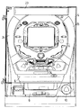
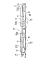
図2に示すように、パチンコ遊技機ではパチンコ機本体1を中心としてその他のパネル状の構成部材がその前後方向に積層状に配置されている。パチンコ機本体1の上半身に形成された遊技盤取り付けスペース2には遊技盤3が嵌合されている。遊技盤3の前方位置には扉枠5が配設されている。扉枠5は金属製ベースとしての取り付けフレーム4をベースとして機能部品としてのプラスチックの扉枠本体15が装着されて構成されている。取り付けフレーム4には機能部品としてのガラス窓G及び同取り付けフレーム4に装着された機能部品としての第1〜第3のLED基板L1〜L3、扉枠本体15の下部位置に装着された機能部品としての上受け皿6が装着されている。扉枠5に関しては詳しく後述する。
As shown in FIG. 2, in the pachinko gaming machine, other panel-like constituent members are arranged in a stacked manner in the front-rear direction with the
パチンコ機本体1において遊技盤3の下方位置にはカバープレート7が配設されている。カバープレート7はパチンコ機本体1に対して固着されている。カバープレート7の裏面にはパチンコ球発射機構8が配設されている。カバープレート7には前方に突出形成した下受け皿9が形成されている。下受け皿9の右側方にはパチンコ球発射機構8に連動する操作ハンドル10が取付けられている。
In the
遊技盤3の後方位置にはこれらを背面から覆うように機構盤11が配設されている。機構盤11の下方には取り付けベース12が配設されている。取り付けベース12は機構盤11とは別体に構成されたパチンコ機本体1に装着される部材であって、各種基板が搭載されている。
A
これら各パネルは主となるパチンコ機本体1を介して額縁状に枠組みされた四角形の木製外枠13に装着されている。パチンコ機本体1は木製外枠13に対して着脱可能に嵌合されている。
Each of these panels is attached to a rectangular wooden
次にこのように構成されるパチンコ遊技機における扉枠5において特に扉枠本
体15及び取り付けフレーム4の構成を中心に説明する。
(実施の形態1)
まず扉枠本体15の構成について説明する。図1及び図2に示すように、プラスチック製の扉枠本体15は中央にガラス窓G用の略円形の大開口部21が形成された略長方形板体とされている。大開口部21からは背後の遊技盤3の前面に形成された遊技面22が露出される。扉枠本体15前面側において大開口部21の上部の装着部15aには正面形状略長方形の第1の電飾パネル23が配設されている。扉枠本体15前面側において大開口部21の左右の装着部15b,15cには第2の電飾パネル24,25が配設されている。両第2の電飾パネル24,25は互いに対称な弧状部材であって、第1の電飾パネル23とともに大開口部21を包囲している。
Next, the structure of the door frame
(Embodiment 1)
First, the configuration of the door frame
両第2の電飾パネル24,25の下端には同両第2の電飾パネル24,25と連続する透明パネル30が配設されている。これら各パネル23〜25,30は機能部品を構成し、扉枠本体15の前面側から装着可能とされている。各パネル23〜25,30は図示しないビスによって背面側から固定されるようになっている。図5に示すようにする。図1における扉枠本体15の左側面位置には取り付けフレーム4との間でヒンジ部26を構成する係合部材27が形成されている。
A
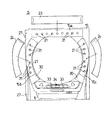
図4に示すように、扉枠本体15の前記各電飾パネル23〜25の配置位置には複数の円形形状の透孔31が形成されており、後述するLEDが同透孔31から前方に露出するようになっている。また、透明パネル30位置においては方形の大型透孔32が形成されており、透明パネル30を通して遊技部としての遊技面に貼付された検閲シール等が目視できるようになっている。
As shown in FIG. 4, a plurality of circular through
図1〜図5に示すように、大開口部21の前面側中央下部位置には機能部品としての上受け皿6が形成されている。上受け皿6と大開口部21の間には球貸し用の操作ボタン33とカードの残量を7セグスタイルで表示する表示パネル34が配設されている。これら操作ボタン33や表示パネル34は機能部品を構成する。
As shown in FIGS. 1 to 5, an
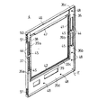
扉枠本体15は取り付けフレーム4に対して装着されるようになっている。図6〜図8、図26〜図28に示すように、取り付けフレーム4は合金をプレス成形して得られる長方形形状の外郭をなすフレーム本体35を有している。フレーム本体35の全外周縁にはフレーム本体35から前方に突出したフランジ37が形成されている。フレーム本体35の中央位置には大きく方形に開口された大開口部38が形成されている。フレーム本体35において大開口部38の左右に配置された部分を左右の縦フレーム35a,35bとし、大開口部38の上下に配置された部分を上下フレーム35c、35dとする。扉枠本体15に取り付けフレーム4が装着された状態において縦フレーム35a,35bは扉枠本体15の大開口部21の左右位置を補強し、上下フレーム35c、35dは扉枠本体15の大開口部21の上下位置を補強する。
The door frame
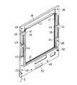
図6、図7、図27及び図28に示すように、大開口部38の全周縁であってフレーム本体35の前面側には凹部39が形成されている。同凹部39の左右の内周縁は折り曲げ形成されてフレーム本体35の裏面側に突出されており左右突出部39a,39bとされている。左右突出部39a,39bは上下方向に沿って延出させられ、同左右突出部39a,39bにはそれぞれ左右の案内レール41が装着されている。同凹部39の下部内周縁は折り曲げ形成されてフレーム本体35の裏面側に突出されており下部突出部39cとされている。下部突出部39cは左右方向に沿って延出させられ、同下部突出部39cには支持レール42が装着されている。
As shown in FIGS. 6, 7, 27, and 28, a
ガラス窓Gは左右の案内レール41に案内された状態で支持レール42によって下方から支持されるようになっている。本実施の形態1ではフレーム本体35に対して後方に向かって案内レール41及び支持レール42が突出されているためこれらに支持されているガラス窓Gはフレーム本体35の裏面に配設されることとなる。ガラス窓Gは更に後方の遊技盤3の遊技面との間隔も考慮されて配置される。図27に示すように、ガラス窓Gが案内レール41及び支持レール42に支持された状態でフレーム本体35のどの部分にも接触することはない。
The glass window G is supported from below by the
フレーム本体35の大開口部38の左右位置、すなわち左右の縦フレーム35a,35bには上下方向に延出された第1の機能部品取り付け口44が形成されている。同取り付け口44はそれぞれ左右位置において上下2箇所に直列状に合計4つの孔として配設されている。同各取り付け口44下端縁には左右方向に延出された補強リブ45が前方に向かって突出形成されている。補強リブ45はプレス加工によってフレーム本体35と一体的に形成されている。取り付けフレーム4の大開口部38の上部位置、すなわち上部フレーム35cには左右方向に延出された第2の機能部品取り付け口46が形成されている。同各取り付け口46下端縁には左右方向に延出された補強リブ47が前方に向かって突出形成されている。補強リブ47はプレス加工によってフレーム本体35と一体的に形成されている。フレーム本体35には同フレーム本体35を扉枠本体15に装着するための固定ビス(図示せず)用の取り付け孔48が散点的に配設されている。
First functional
図8に示すように、左縦フレーム35aには外枠13に対して扉枠5を固定させるためのラッチ49が上下2箇所に後方に向かって突設されている。右縦フレーム35bには遊技盤3に対して係合されて扉枠5を片持ちに保持するための支持金具50が上下2箇所に形成されている。図6及び図7に示すように、支持金具50に隣接してヒンジ部26を構成する係合ピン51が形成されている。図17に示すように係合ピン51は前記扉枠本体15側の係合部材27内に挿入された状態でヒンジ部26を構成するため扉枠本体15は取り付けフレーム4(フレーム本体35)に対してヒンジ部26を中心に回動可能となる。
As shown in FIG. 8, latches 49 for fixing the
図8に示すように、フレーム本体35にはシール52が貼付されている。シール52には取り付けフレーム4に装着されたLED基板L1〜L3の廃棄時期(つまりいつまで使用できるかのデータ)が記載されており、パチンコ遊技機を回収した際に再度LED基板L1〜L3を他のパチンコ遊技機に搭載してもよいかどうかの指標となる。また、図6〜8に示すように、フレーム本体35にはアース線Eが接続されておりパチンコ遊技機をセットした状態で蓄積された静電気をアーシングして放電するようになっている。
As shown in FIG. 8, a
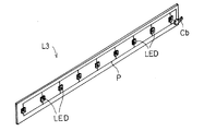
次にこのような構成の取り付けフレーム4に対して装着される第1〜第3のLED基板L1〜L3について説明する。図9及び図10に示すように、各LED基板L1〜L3は基板表面Laに発光部としての複数のLEDが配設され、基板表面LaからはケーブルCbが延出されている。基板表面にはLED用の配線パターンPがプリントされている。第1〜第3のLED基板L1〜L3はそれぞれ取り付けフレーム4のフレーム本体35の前面の左右及び上部装着部35a,35b,35cにそれぞれ装着されるようになっている。
Next, the first to third LED boards L1 to L3 mounted on the mounting
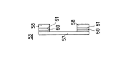
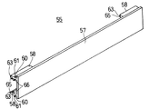
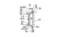
第1〜第3のLED基板L1〜L3は仲介部材としての第1及び第2の連結キャッチ53,55を介してフレーム本体35に対して固着される。図11〜図16に示すように、ABS樹脂製の第1及び第2の連結キャッチ53,55は長方形形状のキャッチ本体57と、同キャッチ本体57の前面側両端寄りから前方に向かって突出する一対の揺動脚58とにより基本的な構成が形成されている。対向配置された一対の揺動脚58の外側面には係合部としての第1の押さえ部60が形成されている。第1の押さえ部60は揺動脚58の側面長手方向に沿って延出されており、その前面にはテーパ状の案内面61が形成されている。揺動脚58の内側面には係合部としての第2の押さえ部63が形成されている。第2の押さえ部63は揺動脚58の側面長手方向に沿って延出されており、その前面にはテーパ状の案内面65が形成されている。第2の押さえ部63から若干キャッチ本体57に寄った位置には棚部66が形成されている。
The first to third LED boards L1 to L3 are fixed to the
第1及び第2の連結キャッチ53,55による第1〜第3のLED基板L1〜L3の詳しい装着作用については後述する。 Detailed mounting action of the first to third LED boards L1 to L3 by the first and second connection catches 53 and 55 will be described later.
次に、第1〜第3のLED基板L1〜L3の取り付けフレーム4への装着作業及び扉枠本体15の取り付けフレーム4への装着作業について説明する。
Next, the mounting operation of the first to third LED substrates L1 to L3 to the mounting
まず、第1〜第3のLED基板L1〜L3の取り付けフレーム4への装着作業について説明する。LED基板L1の装着作用についてはLED基板L2と基本的に同じであるためLED基板L2側の装着作業のみ説明する。
First, the mounting operation of the first to third LED substrates L1 to L3 to the mounting
作業者はまず第1の連結キャッチ53を把持し、同連結キャッチ53を取り付けフレーム4の第2の機能部品取り付け口46に対して図18に示すように取り付けフレーム4の後方から装着していく。
First, the operator grasps the
図21(a)に示すように、第1の連結キャッチ53の揺動脚58を第1の機能部品取り付け口44に挿入させる。すると対向する揺動脚58の間隔はちょうど同取り付け口44の幅と等しいためすみやかに挿入されて行き、揺動脚58の外側面形成されている第1の押さえ部60が同取り付け口44の縁部44aと当接する。この段階で更に第1の連結キャッチ53を同取り付け口44方向に押して行くと図18(b)に示すように揺動脚58は案内面61を介して縁部44aによって押動され徐々に内側に撓んでいく。そして、揺動脚58が進出していって縁部44aと第1の押さえ部60との係合状態が解除されると図19及び図21(c)に示すように揺動脚58は自身の弾性作用によって戻る。この状態で第1の連結キャッチ53はキャッチ本体57と第1の押さえ部60とによって縁部44a位置のフレーム本体35を挟持することとなり同取り付け口44位置に固定されることとなる。このように第1の連結キャッチ53が装着された状態でちょうど第1の連結キャッチ53は補強リブ45の上に載置されることとなり(図19,図20、図26等参照)、補強リブ45は第1の連結キャッチ53の一種の底板としての役割を果たすこととなる。
As shown in FIG. 21A, the
このような作業を上下の第1の連結キャッチ53に対して行う。 Such an operation is performed on the upper and lower first connection catches 53.
次いで、このように固定された第1の連結キャッチ53に対して図10に示す第1のLED基板L1を図19に示すように取り付けフレーム4の前方から装着していく。
Next, the first LED board L1 shown in FIG. 10 is attached to the
図21(d)に示すように、第1のLED基板L1を揺動脚58の第2の押さえ部63の案内面65に当接させる。この段階で更に第1のLED基板L1を第1の連結キャッチ53方向に押して行くと図21(e)に示すように揺動脚58は案内面65を介して第1のLED基板L1に押動され徐々に内側に撓んでいく。そして、揺動脚58が進出していって第1のLED基板L1と第1の押さえ部60との係合状態が解除されると図20及び図21(f)に示すように揺動脚58は自身の弾性作用によって戻る。この状態で第1のLED基板L1は第2の押さえ部63と棚部66とによって挟持されることとなり第1の連結キャッチ53を介して同取り付け口44位置に固定されることとなる。
As shown in FIG. 21 (d), the first
第1及び第2のLED基板L1,L2をこのように装着した後、第3のLED基板L3を装着するために第2の連結キャッチ55を第2の機能部品取り付け口46に対して図22に示すように取り付けフレーム4の後方から装着していく。第2の連結キャッチ55の装着作業は図25(a)〜図25(c)に示す通りである。この一連の作用は上記第1の連結キャッチ53と同じであるため説明を省略する。
After mounting the first and second LED boards L1 and L2 in this way, the
次いで、このように固定された第2の連結キャッチ55に対して図9に示す第3のLED基板L3を図23に示すように取り付けフレーム4の前方から装着していく。第3のLED基板L3の装着作業は図25(d)〜図25(f)に示す通りである。この一連の作用は上記第1のLED基板L1と同じであるため説明を省略する。
Next, the third LED board L3 shown in FIG. 9 is attached to the
このLED基板L1〜L3のLED基板用フレーム16への装着作業はパチンコ遊技機組立ライン工程とは別のラインにて前もって行っておくことが可能であ
る。
The mounting operation of the LED boards L1 to L3 to the LED board frame 16 can be performed in advance on a line different from the pachinko gaming machine assembly line process.
次いでこのように第1〜第3のLED基板L1〜L3を装着した状態の取り付けフレーム4の前面側に扉枠本体15を装着する。すなわち作業者は図17に示すように取り付けフレーム4側の係合ピン51に対して扉枠本体15側の係合部材27を嵌合させてヒンジ部27とし、取り付けフレーム4に対して扉枠本体15を片持ちに保持させるようにする。そして取り付けフレーム4と扉枠本体15とを重ね合わせ前記ビス止め用のビス孔48に対してビス59を螺着させて取り付けフレーム4と扉枠本体15とを固定する(図29)。
Next, the door frame
このように構成することで本実施の形態1では次のような効果を奏する。
(1)従来金属フレームは扉枠本体15等の強度を補完する目的以外には用いられてはおらず、機能部品を装着するベースとして金属製のベースを用いるという発想はなかった。このような構成とすれば様々な機能部品が必要となってきている状態においてプラスチック製のベースに多くの機能部品を装着させて強度低下に陥るといった不具合が生じることがなくなる。また、金属フレーム4側にこのようにLED基板L1〜L3を装着させることで扉枠本体15側のLED基板L1〜L3と重なった位置には他の機能部品を配置することもでき、パネル体としての扉枠5の機能部品を装着する裕度が生まれる。
(2)機能部品が増加してきた場合にこれらをすべて扉枠本体15にそれぞれ別個に装着するとした場合には扉枠本体15にかかる荷重も増加し構造的にも複雑化することとなる。しかし、このように取り付けフレーム4(フレーム本体35)に一部(あるいは全部)の機能部品を分担させることでそのような問題が解消されることとなる。
(3)前もって取り付けフレーム4にLED基板L1〜L3を装着しておけば取り付けフレーム4を扉枠本体15に対して装着するだけでLED基板L1〜L3の配置も可能となるため製造ラインにおけるLED基板L1〜L3の取り付け作業が簡略化でき作業効率が向上する。
(4)取り付けフレーム4に対して扉枠本体15はヒンジ部26によって開放可能とされている。つまり扉枠本体15のみを取り付けフレーム4に対して開放してその裏面を露出させることができ、また、取り付けフレーム4については機能部品(ここではLED基板L1〜L3)が装着された前面を露出させることができるわけである。従って、点検作業等において扉枠本体15を取り付けフレーム4に対して開放させることが容易となり作業効率が極めて向上する。
(5)取り付けフレーム4にLED基板L1〜L3を装着するようにしたため取り付けフレーム4自体の剛性も向上することとなる。
(6)取り付けフレーム4は金属製であって、成形上の制限からこれに装着させる機能部品(ここではLED基板L1〜L3)を掛止するための構造を容易に形成することは困難である。しかし、上記のように第1及び第2の連結キャッチ53,55を使用してこれを介してLED基板L1〜L3を装着するようにしている。これによって機能部品の取り付けが可能となっている。
With this configuration, the first embodiment has the following effects.
(1) Conventionally, the metal frame is not used except for the purpose of complementing the strength of the door frame
(2) When functional parts are increased, if all of them are separately mounted on the door frame
(3) If the LED boards L1 to L3 are mounted on the mounting
(4) The door frame
(5) Since the LED boards L1 to L3 are mounted on the mounting
(6) The mounting
また、取り付けフレーム4とは別個に成形できる連結キャッチ53,55は自由な形状とすることができ、取り付けフレーム4に装着する機能部品に応じて自在に変形させることが可能となる。
In addition, the connection catches 53 and 55 that can be molded separately from the mounting
更に、上記連結キャッチ53,55はプラスチック製であるためリサイクル可能である。
(7)フレーム本体35は大開口部38以外に取り付け口44,46を設けるために多くの透孔が形成されることとなる。しかし、上記連結キャッチ53,55によってこの取り付け口44,46は塞がれてしまうため強度の劣化は極力防止されることとなる。
(8)取り付けフレーム4にはフランジ37や凹部39や折り返した突出部39a〜39c等が形成されているため、薄板状であるにもかかわらず曲げ強度を必要十分に得ることができる。
(9)LED基板L1〜L3は一度の使用のみで廃棄するのではなくパチンコ遊技機を回収した後に改めて異なるパチンコ遊技機に搭載可能である。すなわちこれら複数のLED基板L1〜L3はリサイクル可能であるという機能の観点から見た場合共通性を有する。これらはまた、リサイクルしない場合であってもこのようにケーブルCbを有するプラスチック部材として分別廃棄が可能という機能の観点から見た場合にも共通性を有する。
(10)取り付けフレーム4は金属製であってリサイクル可能な機能部品であるためLED基板L1〜L3をリサイクルするとともに自身も回収してリサイクルすることが可能である。
(11)LED基板L1〜L3のリサイクルの限界はシール52の使用日限をチェックすることでそれが可能である。そのため取り付けフレーム4を取り外した段階でシール52を見て再度リサイクルする場合と廃棄する場合に区別して分別することが容易となる。
(12)凹部39内にLED基板L1〜L3のケーブルCbを通すことで周囲の壁面によってケーブルCbは包囲されるため遊技者側からケーブルCbが目視されてしまうことがない。
(13)LED基板L1〜L3を保持した状態で重量のあるこれら連結キャッチ53,55は揺動脚58によって自身で取り付け口44,46に支持されると同時に第1の連結キャッチ53は補強リブ45の上に、第2の連結キャッチ55は補強リブ47の上にそれぞれ載置されることとなる。従って連結キャッチ53,55は取り付け口44,46にしっかりと保持されて脱落することがなくなる。
(14)各第1の連結キャッチ53は補強リブ45の上に載置されることとなる。そのためこれら連結キャッチ53にLED基板L1,L2を装着した状態において補強リブ45が一種の底板となってLED基板L1,L2が下方にスライドして連結キャッチ53から脱落することのないようになっている。
(15)取り付けフレーム4の大開口部38の内周には突出部39a〜39cが形成されているためこれらが一種の遮蔽壁として大開口部38の外側が見えにくくなっている。そのため、遊技者の目を気にすることなく取り付けフレーム4や扉枠本体15の裏面の構造を設計することができる。
(実施の形態2)
実施の形態2は実施の形態1とは異なり第3のLED基板L3の代わりに表示装置70が配設される場合である。図示において実施の形態1と対応する構成については同じ番号を付すことで詳しい説明を省略する。
Furthermore, since the connection catches 53 and 55 are made of plastic, they can be recycled.
(7) Since the frame
(8) Since the
(9) The LED boards L1 to L3 can be mounted on a different pachinko gaming machine after the pachinko gaming machine is collected instead of being discarded only by one use. That is, the plurality of LED substrates L1 to L3 have commonality from the viewpoint of the function of being recyclable. These also have commonality from the viewpoint of the function of being able to be separated and disposed as a plastic member having the cable Cb even when not recycled.
(10) Since the mounting
(11) The limit of recycling of the LED boards L1 to L3 can be achieved by checking the date of use of the
(12) Since the cable Cb is surrounded by the surrounding wall surface by passing the cable Cb of the LED boards L1 to L3 through the
(13) The connection catches 53 and 55 which are heavy while holding the LED boards L1 to L3 are supported by the swinging
(14) Each
(15) Since the projecting
(Embodiment 2)
In the second embodiment, unlike the first embodiment, a
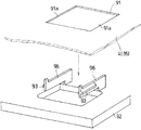
図32及び図33に示すように、フレーム本体35の第2の取り付け口46を利用して同取り付け口46の横幅よりも短い機能部品、例えば液晶画面の表示部71を備えた表示装置70をLED基板用フレーム16に着脱可能に配置するようにしてもよい。
As shown in FIGS. 32 and 33, a
第2の取り付け口46には補強リブ47上に表示装置70が載置され上部装着部35cに対してビス77によって固定されるようになっている。表示装置70の左右には封塞プレート73が第2の取り付け口46の残った空間を封塞するように配置されビス77によって固定されるようになっている。
A
図30及び図31に示すように、扉枠本体15の大開口部21の上部の装着部15aには透孔78が形成されている。フレーム本体35(取り付けフレーム4)に装着された表示装置70は実施の形態1と同様に扉枠本体15に固定され表示部71が透孔78から露出されるようになっている。透孔78には扉枠本体15前面側から表示部71の周縁を包囲するようにカバー79が装着されるようになっている。
As shown in FIGS. 30 and 31, a through
表示装置70は左右の封塞プレート73にもビス77によって固定されるため表示装置70は第2の取り付け口46の左右幅よりも短いにもかかわらずフレーム本体35にしっかりと固定されることとなる。更に、フレーム本体35に左右方向に大きく開放された開口部が形成されるためフレーム本体35単独では強度が劣ってしまう。しかし、封塞プレート73は表示装置70を中間に介して直列状に連結されて第2の取り付け口46を完全に塞ぎ同取り付け口46の補強となるため強度の劣化が防止されることとなる。
Since the
尚、この発明は、次のように変更して具体化することも可能である。 It should be noted that the present invention can be modified and embodied as follows.
・実施の形態1のように第1〜第3のLED基板L1〜L3を直接第1又は第2の連結キャッチ53,55の揺動脚58に把持させるのではなく、支持体を介在させて装着するようにしてもよい。例えば図34及び図35に示すように、LED基板L2にちょうど揺動脚58に把持される形状(つまり上記実施の形態1でのLED基板L1の外形形状のような)の支持板81連結部82を介して連結する。そして、揺動脚58に支持板81を把持させるようにするものである。
The first to third LED boards L1 to L3 are not directly gripped by the
このように構成すると種々の形状とされたLED基板L1〜L3のような機能部品に自在に対応させることができ、特にLED基板L1〜L3のようなLEDの光を前方に発光させる機能部品ではより前方に進出させるような設計が可能となるため有利である。 If comprised in this way, it can be made to respond | correspond freely to functional components like LED board L1-L3 made into various shapes, Especially in the functional component which light-emits LED light like LED board L1-L3 ahead. This is advantageous because it allows a design to advance further forward.
・上記各実施の形態では個々の連結キャッチ53,55毎に1つの第1〜第3のLED基板L1〜L3を把持するようにしていたが、例えば図36に示すように隣接する連結キャッチ53で1つのLED基板L2を把持するようにしてもよい。 In each of the above embodiments, one of the first to third LED boards L1 to L3 is held for each of the connection catches 53 and 55. For example, as shown in FIG. Thus, one LED substrate L2 may be held.
・連結キャッチ53,55の形状は上記各実施の形態に限定されることはない。例えば、図37のように連結キャッチ55のキャッチ本体57の両端にのみ揺動脚58を形成してもよい。すなわち、上記実施の形態1の第2の連結キャッチ55の揺動脚58とは90度ずれた向きに揺動脚58を配置するようにしてもよい。このような向きにして上記第2の同取り付け口46とは別位置で揺動脚58の作用によって装着するようにしてもよい。その他、キャッチ本体57の形状を変形させたり揺動脚58の幅を変更する等は自由である。
The shape of the connection catches 53 and 55 is not limited to the above embodiments. For example, as shown in FIG. 37, the
・連結キャッチ53,55の材質はその他のプラスチック製としてもよい。また、弾性体(例えば合成ゴム)で構成するようにしてもよい。弾性体とすれば連結キャッチ53,55が大きく撓むため第1〜第3のLED基板L1〜L3の撓
みが極めて少なくなる。
-The material of the connection catches 53 and 55 may be made of other plastics. Moreover, you may make it comprise with an elastic body (for example, synthetic rubber). If the elastic body is used, the connection catches 53 and 55 are greatly bent, so that the bending of the first to third LED boards L1 to L3 is extremely reduced.
・上記実施の形態ではシール52に記載された日付によってリサイクル可能回数をチェックするようになっていたが、その他のリサイクル回数確認手段として例えばバーコード、QRコードを使用するようにしてもよい。また、リサイクル回数確認手段としてシール52以外にICチップやメモリカードを使用するようにしてもよい。
In the above embodiment, the recyclable number is checked based on the date written on the
・上記実施の形態では揺動脚58のような爪としての押さえ部63やビス77によって機能部品(LED基板L1〜L3、表示装置70)を固定するようにし
いたが他の手段であっても構わない。
In the above embodiment, the functional parts (LED boards L1 to L3, display device 70) are fixed by the
・図38に示すように、ガラス窓Gを取り付けフレーム4の前面側に配置するようにしてもよい。この場合には取り付けフレーム4の裏面側に配置する場合に比べて遊技盤3から離間した位置に配置されることとなるため。このように後方に後退した段違い部85を形成することで上部装着部35a、35bを基準として若干後方位置に配置するようにしてもよい。段違い部85は同時に大開口部38の補強ともなる。図38に示すように、セット状態において段違い部85は遊技盤3側に形成された凹部86に嵌合されるためガラス窓Gのぐらつきが防止される(ガラス窓Gは自体は遊技盤3にもフレーム本体35にも接触することはない)。
As shown in FIG. 38, the glass window G may be arranged on the front side of the mounting
・図39に示すように、案内レール41をガラス窓Gを取り付けフレーム4の前面側に装着するようにしてもよい。この場合ではガラス窓G自体はフレーム本体35よりも後方位置に配置されるものの、案内レール41自体はフレーム本体35の前面側に取り付けられている。
As shown in FIG. 39, the
・取り付けフレーム4に対する機能部品の装着は種々の手段が考えられるが、図40に示すように、取り付けフレーム4に形成された透孔91に対して装着する機能部品92に向かい合って形成された一対の押さえ部93を設けたレバー95,96によって透孔91の相対向する内周縁91aと押さえ部93とを係合させるようにしてもよい。このような片持ち横爪方式のレバー95,96であれば内周縁91aの長手方向に沿って広く押さえ付けることが可能であるとともに、レバー95,96が水平方向に延出されるため前後方向に突起してパネル体の厚みが増してしまうようなことがない。このようにすればビスを使用しなくともしっかりとLED基板Lを保持させることができる。また、レバー95,96を揺動させることで容易に着脱が可能となる。
Various means are conceivable for mounting the functional component on the mounting
もちろん、このようなレバー95,96と上記ビス77等の併用は構わない。
Of course,
・上記実施の形態ではLED基板L1〜L3はフレーム本体35(取り付けフレーム4)の前面側に配設されていたが、フレーム本体35の裏面側に配設するようにしてもよい。その場合にはLEDの光が第2の同取り付け口46に装着されている第2の連結キャッチ55に邪魔されないように図41に示すように第2の連結キャッチ55に透孔98を形成する。これによってLEDの光が透孔98を通して前方に照明されるようになる。
In the above embodiment, the LED boards L1 to L3 are disposed on the front side of the frame body 35 (mounting frame 4), but may be disposed on the back side of the
・取り付けフレーム4(フレーム本体35)の形状は上記に限定されることはない、フランジ37の形状や突出量、取り付け口44,46の形状、配置位置、数は適宜変更可能である。
The shape of the mounting frame 4 (frame main body 35) is not limited to the above, and the shape and the protruding amount of the
・上記実施の形態ではフランジ37側をフレーム本体35に当接させたが、逆向きであってもよい。
In the above embodiment, the
・上記各実施の形態では先にすべての第1の連結キャッチ53(又は第2の連結キャッチ55)をフレーム本体35に装着してからLED基板L1(又はL2,L3)を装着するようにしていたが、これは装着作業の一例であって例えば連結キャッチ53を1つ着けるごとにLED基板L1(又はL2)を装着するようにしてもよいし、すべての連結キャッチ53,55を着けてからLED基板L1〜L3を装着するようにしてもよい。
In each of the above embodiments, all the first connection catches 53 (or second connection catches 55) are first attached to the
・上記各実施の形態ではビス59によって扉枠本体15に対して取り付けフレーム4を固定していたが、ビス59以外の手段、例えば扉枠本体15に爪部材を形成し取り付けフレーム4側の係合部材に対して掛止させるようにして固定してもよい。また、ビス59と爪部材をを併用するようにしてもよい。
In each of the above embodiments, the mounting
・上記ケーブルCbのような配線を保持する保持手段を設けるようにしてもよい。 -You may make it provide the holding means to hold | maintain wiring like the said cable Cb.
・上記取り付けフレーム4の大開口部38の内周には突出部39a〜39cが形成されておりこれらが一種の遮蔽壁として大開口部38の外側が見えにくくなっていた。しかし、逆に突出部39a〜39cをそれほど突起させずに内部を積極的に見せるようにしてもよい。
・上記実施の形態では機能部品の例として第1〜第3のLED基板L1〜L3と表示装置70を例として挙げたが、その他装飾用のカバー、ガラス保持枠、中継基板、配線保持部材等の機能部品を装着するようにしてもよい。
In the above embodiment, the first to third LED boards L1 to L3 and the
・前記取り付けフレーム4では特に扉枠5のための装飾用の機能部品であるLED基板L1〜L3と表示装置70を装着していたために、これら機能部品は取り付けフレーム4の前面側に配置されていたが、部品によっては裏面に配設するようにしても構わない。
In the mounting
・上記各実施の形態はパネル体として特に扉枠5に反映した実施の形態として説明したが、他のパネル体、例えばパチンコ機本体1や機構盤11に応用することも可能である。
-Although each said embodiment was demonstrated as embodiment reflected especially in the
・本実施の形態はいわゆるパチンコ機以外の例えばスロットマシンやパチロットにも応用可能である。 This embodiment can be applied to slot machines and patty lots other than so-called pachinko machines.
・その他、本発明の趣旨を逸脱しない態様で実施することは自由である。 -Besides, it is free to implement in a mode that does not depart from the gist of the present invention.
本発明の目的を達成するために上記実施の形態から把握できるその他の技術的思想について下記に付記として説明する。
(1)前記機能部品は前記金属製ベースに着脱可能に装着されることを特徴とする請求項1に記載の遊技機。
Other technical ideas that can be grasped from the above-described embodiments in order to achieve the object of the present invention will be described below as additional notes.
(1) The gaming machine according to
これによって機能部品の交換やリサイクルが容易に行えることとなる。
(2)前記機能部品には同面に形成されたレバーを設け、同レバーを常時は同レバーに形成された係合部を前記金属製ベースに形成された透孔の周縁と干渉させるとともに、同基部を中心として同透孔の周縁から離間する方向に向かって撓ませることで同金属製ベースとの機能部品の着脱時には同金属製ベースと干渉しない位置に移動可能としたことを特徴とする請求項1又は付記1に記載の遊技機。
This facilitates replacement and recycling of functional parts.
(2) The functional component is provided with a lever formed on the same surface, and the lever is normally made to interfere with the periphery of the through hole formed in the metal base with the engaging portion formed on the lever. It is possible to move to a position that does not interfere with the metal base when the functional part is attached to or detached from the metal base by bending in the direction away from the periphery of the through hole with the base as the center. The gaming machine according to
例えば上記実施の形態の図40のいわゆる片持ち横爪方式のレバー95,96が考えられる。これによってレバーを撓ませることで容易に金属製ベースに対して機能部品を着脱することが可能となる。
(3)前記機能部品は仲介部材を介して前記金属製ベースに着脱可能に装着されることを特徴とする請求項1に記載の遊技機。
For example, the so-called cantilever side claw levers 95 and 96 of FIG. This makes it possible to easily attach / detach the functional component to / from the metal base by bending the lever.
(3) The gaming machine according to
これによって加工しにくい金属製ベースに対して複雑な取り付けようの加工を施さなくとも仲介部材を介することによって確実に機能部品を装着することができる。
(4)前記仲介部材は前記金属製ベースに形成された透孔に対して固定手段によって固定されることを特徴とする付記3に記載の遊技機。
As a result, the functional component can be securely mounted by way of the mediating member without performing complicated mounting processing on the metal base that is difficult to process.
(4) The gaming machine according to
これには例えば上記実施の形態の揺動脚58のように爪によって固定する場合や、ビス77によって螺着する場合がある。
(5)前記仲介部材にはレバーを設け、同レバーを撓ませることで同レバーに形成された係合爪によって前記金属製ベースに形成された透孔に掛止させ、もって仲介部材を同ベースに装着するようにしたことを特徴とする付記3又は4のいずれかに記載の遊技機。
For example, it may be fixed by a claw as in the
(5) The mediating member is provided with a lever, and the lever is bent to be engaged with a through hole formed in the metal base by an engaging claw formed on the lever. The gaming machine according to any one of
レバーとは上記実施の形態では揺動脚58であり、係合爪とは例えば上記各実施の形態のような押さえ部60がこれに相当する。このような装着手段を採用することで作業の効率化を図ることができる。
(6)前記係合爪は前記透孔の対向する両縁部に係合爪が係合されるように対向配置されていることを特徴とする付記5に記載の遊技機。。
The lever is the
(6) The gaming machine according to
これによって仲介部材は金属製ベースに対してしっかりと固定される。
(7)前記レバーの係合爪には機能部品の同係合爪に対する押圧による圧力を分散させ同レバーに前記透孔の側方に向かって撓ませる方向のベクトル成分を付与する斜状部を形成したことを特徴とする付記5又は6に記載の遊技機。
As a result, the intermediate member is firmly fixed to the metal base.
(7) The engaging claw of the lever is provided with a slanted portion for dispersing a pressure applied to the engaging claw of the functional component and applying a vector component in a direction in which the lever is bent toward the side of the through hole. The gaming machine according to
これによって仲介部材を金属製ベースの透孔に押し込むだけで斜状部の作用でレバーが揺動し、仲介部材を透孔位置に装着させることができるので作業が効率化する。斜状部とは上記実施の形態では案内面61である。
As a result, the lever is swung by the action of the slanted portion simply by pushing the mediating member into the through hole of the metal base, and the mediating member can be mounted at the through hole position, so that the work becomes efficient. The slanted portion is the
これによってワンタッチで仲介部材を装着することができ、作業の効率化とコストダウンに貢献する。
(8)前記透孔は装着する前記仲介部材よりも大きく開口しており、補助部材によって仲介部材とともに同透孔を塞ぐようにしていることを特徴とする付記3〜7のいずれかに記載の遊技機。
This makes it possible to attach the mediating member with a single touch, contributing to work efficiency and cost reduction.
(8) The through hole is larger than the mediating member to be mounted, and the through hole is closed together with the mediating member by an auxiliary member. Gaming machine.
これによって金属製ベースに種々の形状の仲介部材を装着することができひいては仲介部材に保持される機能部品の大きさの如何にかかわりなく装着できることとなる。この場合に透孔は仲介部材と補助部材によって完全に塞がれなくともよい。補助部材とは上記実施の形態では封塞プレート73が相当する。
(9)前記2以上の仲介部材は1つの前記機能部品を保持することを特徴とする付記3〜8のいずれかに記載の遊技機。
As a result, various shapes of mediating members can be mounted on the metal base, and thus can be mounted regardless of the size of the functional component held by the mediating member. In this case, the through hole may not be completely blocked by the mediating member and the auxiliary member. The auxiliary member corresponds to the sealing
(9) The gaming machine according to any one of
これによって一つの仲介部材では取り付けにくい機能部品の装着が可能となる。
(10)前記仲介部材は透孔への装着状態で下方から支持手段によって支持されていることを特徴とする付記3〜9のいずれかに記載の遊技機。
This makes it possible to mount functional parts that are difficult to attach with a single mediating member.
(10) The gaming machine according to any one of
これは特に重量のある機能部品例えば表示装置を搭載したユニット化ベースにおいて有効である。支持手段とは上記実施の形態では補強リブ45,47等である。
(11)前記支持手段は前記仲介部材に支持された前記機能部品の下方への脱落を防止する機能を兼ねていることを特徴とする付記10に記載の遊技機。
This is particularly effective on a unitized base equipped with a heavy functional component such as a display device. The support means is the reinforcing
(11) The gaming machine according to
例えば上記実施の形態1のように連結キャッチ53に支持されたLED基板L2は構造上補強リブ45がなければ揺動脚58をスライドして下方に脱落してしまうこととなる。これによって付記8の効果に加え脱落が防止されることとなる。
(12)前記仲介部材はプラスチック製であることを特徴とする付記3〜11のいずれかに記載の遊技機。
For example, as in the first embodiment, the LED board L2 supported by the
(12) The gaming machine according to any one of
これによって機能部品の形状にうまく適合した部品に成形することが可能である。また、リサイクルが可能である。
(13)前記仲介部材は弾性素材から構成されていることを特徴とする付記3〜11のいずれかに記載の遊技機。
As a result, it is possible to form a component that is well adapted to the shape of the functional component. It can also be recycled.
(13) The gaming machine according to any one of
これによって機能部品を撓ませずに仲介部材側を撓ますことが容易となるため機能部品に対する負荷が少なくなる。
(14)前記金属製ベースには補強加工が施されていることを特徴とする請求項1若しくは付記1〜13のいずれかに記載の遊技機。
As a result, it is easy to bend the mediating member side without bending the functional component, so the load on the functional component is reduced.
(14) The gaming machine according to any one of
補強加工とは上記各実施の形態ではフランジ37、凹部39、突出部39a〜39c、段違い部85等が相当する。これによって金属製ベースの強度が増加する。
(15)前記金属製ベースには電機部品用の配線の収納部が形成されていることを特徴とする請求項1若しくは付記1〜14のいずれかに記載の遊技機。
In the above embodiments, the reinforcing process corresponds to the
(15) The gaming machine according to any one of
上記実施の形態では凹部39が相当する。凹部39は同時にベースの補強も兼ねている。
(16)前記金属製ベースには同ベースに装着される前記機能部品についての情報の読み取りが可能とされた識別媒体が配設されていることを特徴とする請求項1若しくは付記1〜15のいずれかに記載の遊技機。
In the above embodiment, the
(16) The metal base is provided with an identification medium capable of reading information on the functional parts mounted on the base. A gaming machine according to any one of the above.
情報とは例えばリサイクル回数、リサイクル可能な日限情報、材質、製造年月日等が挙げられる。識別媒体としては例えば上記実施の形態のようなシール74以外にICチップ、メモリカード等が挙げられる。情報の開示手段としては上記実施の形態のように直接日付を記載することの他に、識別コード(例えばバーコード、QRコード)を使用することが可能である。識別コードを使用した場合では読み取り装置が必要となるため情報の秘密性が保持できるという利点がある。
(17)前記金属製ベースには外部端子に接続されたアース線が配設されていることを特徴とする請求項1若しくは付記1〜16のいずれかに記載の遊技機。
The information includes, for example, the number of times of recycling, date information that can be recycled, material, date of manufacture, and the like. Examples of the identification medium include an IC chip and a memory card in addition to the seal 74 as in the above embodiment. As means for disclosing information, it is possible to use an identification code (for example, a bar code, a QR code) in addition to directly describing the date as in the above embodiment. When the identification code is used, since a reading device is required, there is an advantage that confidentiality of information can be maintained.
(17) The gaming machine according to any one of (1) and (1) to (16), wherein the metal base is provided with a ground wire connected to an external terminal.
これによってパチンコ遊技機を使用した際に蓄積されるた静電気をアーシングして放電することが可能となっている。
(18)金属製ベースに形成された前記透孔は装着する基準となる前記機能部品に対してより大きく開口されており余った開口部分を同機能部品と連結された補助部材によって封塞することで異なる種類の機能部品を同透孔に面して配置するようにしたことを特徴とする請求項1若しくは付記1〜17のいずれかに記載の遊技機。
This makes it possible to ground and discharge static electricity accumulated when using a pachinko gaming machine.
(18) The through hole formed in the metal base is opened larger than the functional component serving as a reference for mounting, and the remaining opening is sealed with an auxiliary member connected to the functional component. 18. A gaming machine according to
これによって種々の機能部品を金属製ベースに配置させために透孔を大きく形成しても補助部材によって封塞することで透孔部の補強をすることができる。
(19)前記金属製ベースと同金属製ベースが装着される他の機能部品との間には他の機能部品が挟持されていることを特徴とする請求項1若しくは付記1〜18のいずれかに記載の遊技機。
As a result, even if the through hole is formed large in order to arrange various functional parts on the metal base, the through hole portion can be reinforced by sealing with the auxiliary member.
(19) The other functional component is sandwiched between the metal base and another functional component on which the metal base is mounted. The gaming machine described in 1.
これによって機能部品の機構をより高めることができる。例えばLEDの光を拡散させる散光シートのようなものが考えられる。
(20)前記金属製ベースには遊技盤の遊技面を前方に露出させるための開口部が形成され、同開口部周縁には遮蔽壁が配設されていることを特徴とする請求項1若しくは付記1〜19のいずれかに記載の遊技機。
As a result, the mechanism of the functional component can be further enhanced. For example, a diffuser sheet that diffuses the light of the LED can be considered.
(20) The metal base has an opening for exposing the game surface of the game board to the front, and a shielding wall is disposed around the periphery of the opening. The gaming machine according to any one of
遮蔽壁に阻まれて外側が見えにくくなっている。そのため、遊技者の目を気にすることなくパネル体や機能部品(取り付けフレーム4や扉枠本体15等)の設計をすることができる。
(21)前記金属製ベースに装着される窓ガラス取り付け用のガラス用レールは同金属製ベースを基準として後方位置に配置されていることを特徴とする請求項1若しくは付記1〜20のいずれかに記載の遊技機。
(22)前記金属製ベースに装着される窓ガラス取り付け用のガラス用レールは同金属製ベースを基準として前方位置に配置されていることを特徴とする請求項1若しくは付記1〜21のいずれかに記載の遊技機。
The outside is difficult to see due to the obstruction of the shielding wall. Therefore, it is possible to design a panel body and functional parts (such as the
(21) The glass rail for attaching a window glass to be mounted on the metal base is disposed at a rear position with reference to the metal base. The gaming machine described in 1.
(22) The glass rail for attaching the window glass to be mounted on the metal base is arranged at a front position with reference to the metal base, or any one of
ここに前方位置とはガラス用レール及び窓ガラスとも金属製ベースよりも前方にある場合のみではなく、例えば上記図39に示すようにガラス用レールの取り付け位置が前方にある場合も含む。
(23)前記金属製ベースに隣接する遊技盤には前記ガラス用レールを直接的又は間接的に保持する保持手段が形成されていることを特徴とする請求項1若しくは付記1〜21のいずれかに記載の遊技機。
Here, the front position includes not only the case where both the glass rail and the window glass are in front of the metal base, but also the case where the glass rail mounting position is in front as shown in FIG. 39, for example.
(23) The game board adjacent to the metal base is provided with holding means for directly or indirectly holding the glass rail, or any one of
例えば上記図38に示すように遊技盤3に形成された凹部86が保持手段に該当する。また、間接的とは上記図38のように案内レール41が凹部86に直接係合するのではなく段違い部85を介して係合されているような場合をいう。
(24)前記金属製ベースは同ベースが固定される機能部品(上記実施の形態では扉枠本体15)との間でヒンジ部を中心に互いに回動可能であることを特徴とする請求項1若しくは付記1〜23のいずれかに記載の遊技機。
For example, as shown in FIG. 38, a
(24) The metal base is capable of rotating with respect to a hinge part between the metal base and a functional component to which the base is fixed (in the above embodiment, the door frame body 15). Or the game machine in any one of appendices 1-23.
これによって点検作業等において互いに開放させることができ作業効率が極めて向上する。
(25)前記金属製ベースは同金属製ベースを構成するパネル体とは別のパネル体に対してヒンジ部を中心に回動可能であることを特徴とする請求項1若しくは付記1〜24のいずれかに記載の遊技機。
As a result, they can be opened to each other in inspection work or the like, and work efficiency is greatly improved.
(25) The metal base can be rotated around a hinge portion with respect to a panel body different from the panel body constituting the metal base. A gaming machine according to any one of the above.
他のパネル体とは上記実施の形態では例えばパチンコ機本体1が挙げられる。(26)前記金属製ベースには複数の機能部品装着用の透孔群が形成され、同透孔群には常時は機能部品を装着しない予備的な透孔が含まれることを特徴とする請求項1若しくは付記1〜25のいずれかに記載の遊技機。
In the above embodiment, the other panel body includes, for example, the
これによって、将来の機能部品の変更、例えばリサイクルした金属製ベースに別の機能部品を装着するような対応が可能となる。透孔には直接機能部品を装着しても上記仲介部材を介在させてもよい。
(27)前記複数の機能部品は複数種類の部品から構成されることを特徴とする請求項1若しくは付記1〜26のいずれかに記載の遊技機。
This makes it possible to cope with future functional component changes, such as mounting another functional component on a recycled metal base. The functional member may be directly attached to the through hole, or the mediating member may be interposed.
(27) The gaming machine according to
ここに複数種類とは機能に共通性があっても総体的には異なる機能である場合、例えば上記実施の形態においてLED基板L1〜L3と表示装置70を取り付けフレーム4(フレーム本体35)に搭載させるような場合である。
(28)前記金属製ベースに装着される前記機能部品は電気部品であることを特徴とすることを特徴とする請求項1若しくは付記1〜27のいずれかに記載の遊技機。
Here, when the functions are different from each other even though the functions are common, for example, in the above embodiment, the LED boards L1 to L3 and the
(28) The gaming machine according to any one of (1) and (1) to (27), wherein the functional component mounted on the metal base is an electrical component.
電気部品とは上記LED基板L1〜L3のように発光部品やカード操作機構、各種表示装置、スピーカ、その他電源から電力を供給されるものを広く言う。このようにユニット化ベースに電機部品をまとめることで配線作業や点検の便宜を図ることができ、また、パチンコ遊技機を回収した際にユニット化ベースを取り外しこれをチェックすることで電機部品としてリサイクルするか廃棄するかの判断もできることとなる。
(29)前記金属製ベース又は/及び同金属製ベースに装着される前記機能部品はそのまま再使用することのできる機能を有することを特徴とする請求項1若しくは付記1〜28のいずれかに記載の遊技機。
The electric parts broadly refer to light-emitting parts, card operation mechanisms, various display devices, speakers, and other parts that are supplied with power from a power source, such as the LED boards L1 to L3. Collecting electrical parts in a unitized base in this way can facilitate the convenience of wiring work and inspection, and when collecting pachinko machines, remove the unitized base and check it for recycling as electrical parts You can also decide whether to discard or discard.
(29) The metal base and / or the functional component mounted on the metal base has a function that can be reused as it is, or any one of
このような機能部品は特に大きく加工する必要もなく再利用できることからリサイクル性が高い。例え場上記実施の形態のLED基板L1〜L3が挙げられる。
(30)前記金属製ベースに装着される機能部品は前記仲介部材を介して金属製ベースよりも前方位置或いは後方位置に配置されることを特徴とする請求項1若しくは付記1〜29のいずれかに記載の遊技機。
Such a functional component is highly recyclable because it can be reused without the need for particularly large processing. For example, the LED substrates L1 to L3 of the above-described embodiment may be mentioned.
(30) The functional component mounted on the metal base is disposed at a front position or a rear position with respect to the metal base via the mediating member, or any one of
これによって所望の機能部品をより前方位置或いは後方位置に配置できることとなる。上記実施の形態では揺動脚58に支持される支持板81と連結部82がこれに相当する。
(31)前記複数の機能部品は前記金属製ベースの前面側に配置されることを特徴とする請求項1若しくは付記1〜30のいずれかに記載の遊技機。
As a result, a desired functional component can be arranged at a more forward position or a rear position. In the above embodiment, the
(31) The gaming machine according to
なるべく前方に配置させることが好ましい機能部品にとって有利である。
(32)前記複数の機能部品は前記金属製ベースの裏面側に配置されることを特徴とする請求項1若しくは付記1〜31のいずれかに記載の遊技機。
It is advantageous for a functional component that is preferably arranged as far forward as possible.
(32) The gaming machine according to any one of
なるべく後方に配置させることが好ましい機能部品にとって有利である。
(33)前記金属製ベースには複数の発光部品が装着されることを特徴とする請求項1若しくは付記1〜32のいずれかに記載の遊技機。
It is advantageous for functional parts that are preferably arranged as far back as possible.
(33) The gaming machine according to any one of
これによって特にリサイクル性が重視される発光部品を一括して取り扱うことが可能となる。発光部品とは上記ではLED基板L1〜L3である。
(34)前記金属製ベースの裏面側に前記発光部品が装着される場合には同発光部品の照明が同金属製ベースを通して前方に導かれるように同金属製ベースに透孔が形成されることを特徴とする付記33に記載の遊技機。
This makes it possible to handle light emitting components that are particularly important for recycling. In the above description, the light emitting components are the LED substrates L1 to L3.
(34) When the light emitting component is mounted on the back side of the metal base, a through hole is formed in the metal base so that the illumination of the light emitting component is guided forward through the metal base. 34. The gaming machine according to
これによって発光部品を後方位置に配置する際の照明が可能となる。
(35)前記発光部品が前記仲介部品を介して前記金属製ベースに装着されている場合に、同仲介部品によって前記透孔が塞がれる場合には第2の透孔を同仲介部品に形成して照明が前方に導かれるようにしたことを特徴とする付記34に記載の遊技機。
This enables illumination when the light emitting component is arranged at the rear position.
(35) When the light emitting component is attached to the metal base through the mediating component, and the through hole is blocked by the mediating component, a second through hole is formed in the mediating component. 35. The gaming machine according to
上記実施の形態では図41の透孔98が第2の透孔に相当する。
In the above embodiment, the through
4…取り付けフレーム、5…扉枠、15…扉枠本体、16…LED基板用フレーム、53,55、L1〜l3…LED基板。
DESCRIPTION OF
Claims (1)
複数の機能部品を同じく機能部品としての金属製ベースに対して装着し、前記パネル体を構成するようにしたことを特徴とする遊技機。 In a gaming machine in which a plurality of functional parts are combined to form a single panel body, and the same panel body is assembled and integrated,
A gaming machine characterized in that a plurality of functional parts are mounted on a metal base as a functional part to constitute the panel body.
Priority Applications (1)
| Application Number | Priority Date | Filing Date | Title |
|---|---|---|---|
| JP2008114186A JP4645916B2 (en) | 2008-04-24 | 2008-04-24 | Game machine |
Applications Claiming Priority (1)
| Application Number | Priority Date | Filing Date | Title |
|---|---|---|---|
| JP2008114186A JP4645916B2 (en) | 2008-04-24 | 2008-04-24 | Game machine |
Related Parent Applications (1)
| Application Number | Title | Priority Date | Filing Date |
|---|---|---|---|
| JP2002087893A Division JP4288890B2 (en) | 2002-03-27 | 2002-03-27 | Game machine |
Related Child Applications (1)
| Application Number | Title | Priority Date | Filing Date |
|---|---|---|---|
| JP2010117207A Division JP4788831B2 (en) | 2010-05-21 | 2010-05-21 | Game machine |
Publications (2)
| Publication Number | Publication Date |
|---|---|
| JP2008212707A true JP2008212707A (en) | 2008-09-18 |
| JP4645916B2 JP4645916B2 (en) | 2011-03-09 |
Family
ID=39833405
Family Applications (1)
| Application Number | Title | Priority Date | Filing Date |
|---|---|---|---|
| JP2008114186A Expired - Fee Related JP4645916B2 (en) | 2008-04-24 | 2008-04-24 | Game machine |
Country Status (1)
| Country | Link |
|---|---|
| JP (1) | JP4645916B2 (en) |
Citations (10)
| Publication number | Priority date | Publication date | Assignee | Title |
|---|---|---|---|---|
| JPH0337886U (en) * | 1989-08-21 | 1991-04-12 | ||
| JPH09713A (en) * | 1995-06-19 | 1997-01-07 | Sophia Co Ltd | Game machine |
| JPH09313696A (en) * | 1996-05-29 | 1997-12-09 | Tsugio Kondo | Metal frame structure for pachinko machine |
| JPH1094650A (en) * | 1996-09-24 | 1998-04-14 | Daiichi Shokai Co Ltd | Pachinko machine |
| JPH10263166A (en) * | 1997-03-28 | 1998-10-06 | Sankyo Kk | Pachinko machine |
| JPH11216226A (en) * | 1998-01-30 | 1999-08-10 | Aruze Corp | Game machine |
| JP2000070504A (en) * | 1998-09-01 | 2000-03-07 | Toyomaru Sangyo Kk | Pachinko machine |
| JP2001334051A (en) * | 2000-05-29 | 2001-12-04 | Kyoraku Sangyo | Pachinko game machine |
| JP2002085758A (en) * | 2000-09-14 | 2002-03-26 | Kyoraku Sangyo | Upward-movement preventing member for transparent plate in pachinko game machine |
| JP2003117186A (en) * | 2001-10-12 | 2003-04-22 | Adachi Light Co Ltd | Frame for glass door of pachinko machine |
-
2008
- 2008-04-24 JP JP2008114186A patent/JP4645916B2/en not_active Expired - Fee Related
Patent Citations (10)
| Publication number | Priority date | Publication date | Assignee | Title |
|---|---|---|---|---|
| JPH0337886U (en) * | 1989-08-21 | 1991-04-12 | ||
| JPH09713A (en) * | 1995-06-19 | 1997-01-07 | Sophia Co Ltd | Game machine |
| JPH09313696A (en) * | 1996-05-29 | 1997-12-09 | Tsugio Kondo | Metal frame structure for pachinko machine |
| JPH1094650A (en) * | 1996-09-24 | 1998-04-14 | Daiichi Shokai Co Ltd | Pachinko machine |
| JPH10263166A (en) * | 1997-03-28 | 1998-10-06 | Sankyo Kk | Pachinko machine |
| JPH11216226A (en) * | 1998-01-30 | 1999-08-10 | Aruze Corp | Game machine |
| JP2000070504A (en) * | 1998-09-01 | 2000-03-07 | Toyomaru Sangyo Kk | Pachinko machine |
| JP2001334051A (en) * | 2000-05-29 | 2001-12-04 | Kyoraku Sangyo | Pachinko game machine |
| JP2002085758A (en) * | 2000-09-14 | 2002-03-26 | Kyoraku Sangyo | Upward-movement preventing member for transparent plate in pachinko game machine |
| JP2003117186A (en) * | 2001-10-12 | 2003-04-22 | Adachi Light Co Ltd | Frame for glass door of pachinko machine |
Also Published As
| Publication number | Publication date |
|---|---|
| JP4645916B2 (en) | 2011-03-09 |
Similar Documents
| Publication | Publication Date | Title |
|---|---|---|
| JP5440960B2 (en) | Game machine | |
| CN104213365A (en) | Laundry treating apparatus | |
| JP4964919B2 (en) | Game machine | |
| JP4645916B2 (en) | Game machine | |
| JP2007143988A (en) | Game machine | |
| JP4288890B2 (en) | Game machine | |
| JP4788831B2 (en) | Game machine | |
| WO2013061798A1 (en) | Pos terminal device having built-in device with excellent attachment/detachment workability | |
| JP4218252B2 (en) | Game machine | |
| JP2003260237A (en) | Game machine | |
| JP5560952B2 (en) | vending machine | |
| JP4488442B2 (en) | Game machine | |
| JP2004147878A (en) | Game machine | |
| JP2009183402A (en) | Game machine | |
| JP4929985B2 (en) | Amusement machine Shimadai | |
| JP5300110B2 (en) | POS terminal device | |
| JP7127822B2 (en) | game machine | |
| JP2003310974A (en) | Game machine | |
| JP7106119B2 (en) | game machine | |
| JP2000251134A (en) | Exhibition device for automatic vending machine | |
| JP7127824B2 (en) | game machine | |
| JP2008113884A (en) | Game machine island | |
| JP2009129294A (en) | Indicator attachment/detachment structure and indicator attachment/detachment method | |
| JP2003236190A (en) | Game machine | |
| JP2008310492A (en) | Advertising panel for automatic vending machine |
Legal Events
| Date | Code | Title | Description |
|---|---|---|---|
| A131 | Notification of reasons for refusal |
Free format text: JAPANESE INTERMEDIATE CODE: A131 Effective date: 20100326 |
|
| A521 | Request for written amendment filed |
Free format text: JAPANESE INTERMEDIATE CODE: A523 Effective date: 20100524 |
|
| TRDD | Decision of grant or rejection written | ||
| A01 | Written decision to grant a patent or to grant a registration (utility model) |
Free format text: JAPANESE INTERMEDIATE CODE: A01 Effective date: 20101111 |
|
| A01 | Written decision to grant a patent or to grant a registration (utility model) |
Free format text: JAPANESE INTERMEDIATE CODE: A01 |
|
| A61 | First payment of annual fees (during grant procedure) |
Free format text: JAPANESE INTERMEDIATE CODE: A61 Effective date: 20101124 |
|
| FPAY | Renewal fee payment (event date is renewal date of database) |
Free format text: PAYMENT UNTIL: 20131217 Year of fee payment: 3 |
|
| R150 | Certificate of patent or registration of utility model |
Ref document number: 4645916 Country of ref document: JP Free format text: JAPANESE INTERMEDIATE CODE: R150 Free format text: JAPANESE INTERMEDIATE CODE: R150 |
|
| R250 | Receipt of annual fees |
Free format text: JAPANESE INTERMEDIATE CODE: R250 |
|
| R250 | Receipt of annual fees |
Free format text: JAPANESE INTERMEDIATE CODE: R250 |
|
| R250 | Receipt of annual fees |
Free format text: JAPANESE INTERMEDIATE CODE: R250 |
|
| R250 | Receipt of annual fees |
Free format text: JAPANESE INTERMEDIATE CODE: R250 |
|
| R250 | Receipt of annual fees |
Free format text: JAPANESE INTERMEDIATE CODE: R250 |
|
| R250 | Receipt of annual fees |
Free format text: JAPANESE INTERMEDIATE CODE: R250 |
|
| LAPS | Cancellation because of no payment of annual fees |