JP2008205485A - Positive electrode for electric double-layer capacitor using graphite and electric double-layer capacitor - Google Patents
Positive electrode for electric double-layer capacitor using graphite and electric double-layer capacitor Download PDFInfo
- Publication number
- JP2008205485A JP2008205485A JP2008066073A JP2008066073A JP2008205485A JP 2008205485 A JP2008205485 A JP 2008205485A JP 2008066073 A JP2008066073 A JP 2008066073A JP 2008066073 A JP2008066073 A JP 2008066073A JP 2008205485 A JP2008205485 A JP 2008205485A
- Authority
- JP
- Japan
- Prior art keywords
- graphite
- electrode
- electric double
- layer capacitor
- double layer
- Prior art date
- Legal status (The legal status is an assumption and is not a legal conclusion. Google has not performed a legal analysis and makes no representation as to the accuracy of the status listed.)
- Pending
Links
Images


Classifications
-
- Y—GENERAL TAGGING OF NEW TECHNOLOGICAL DEVELOPMENTS; GENERAL TAGGING OF CROSS-SECTIONAL TECHNOLOGIES SPANNING OVER SEVERAL SECTIONS OF THE IPC; TECHNICAL SUBJECTS COVERED BY FORMER USPC CROSS-REFERENCE ART COLLECTIONS [XRACs] AND DIGESTS
- Y02—TECHNOLOGIES OR APPLICATIONS FOR MITIGATION OR ADAPTATION AGAINST CLIMATE CHANGE
- Y02E—REDUCTION OF GREENHOUSE GAS [GHG] EMISSIONS, RELATED TO ENERGY GENERATION, TRANSMISSION OR DISTRIBUTION
- Y02E60/00—Enabling technologies; Technologies with a potential or indirect contribution to GHG emissions mitigation
- Y02E60/13—Energy storage using capacitors
Abstract
Description
本発明は、蓄電要素、特に電気二重層キャパシタに関するものであり、静電容量が大きな電気二重層キャパシタに関するものである。 The present invention relates to a power storage element, particularly an electric double layer capacitor, and more particularly to an electric double layer capacitor having a large capacitance.
蓄電要素や電気二重層キャパシタにおいては、分極性電極として比表面積が大きな活性炭が用いられていた。水溶液を電解液とした場合には、使用可能な耐電圧は、水の電気分解電圧である1V程度であるという問題点があったが、電解液として、有機電解液を用いた場合には、有機電解液の種類によっては、耐電圧は3V以上とすることができるので、耐電圧の上昇に伴って電圧の二乗に比例する静電エネルギーを大きくすることが可能となる。 In power storage elements and electric double layer capacitors, activated carbon having a large specific surface area has been used as a polarizable electrode. When the aqueous solution is used as an electrolytic solution, the usable withstand voltage has a problem that it is about 1 V which is an electrolysis voltage of water. However, when an organic electrolytic solution is used as the electrolytic solution, Depending on the type of the organic electrolyte, the withstand voltage can be set to 3 V or more, so that the electrostatic energy proportional to the square of the voltage can be increased as the withstand voltage increases.
更に、分極性電極を構成する炭素材料として、アルカリ金属とアルカリ金属化合物の少なくとも1種と共にアルカリ金属の蒸気が発生する温度以上で熱処理を行って製造される黒鉛類似の微結晶炭素を有する炭素材料を用いて、電気二重層キャパシタを組み立てた後に、最初に定格電圧以上の電圧を分極性電極間に印加することによって、微結晶炭素の層間に有機電解液における溶質のイオンを挿入させて静電容量を発現させて、従来の活性炭を使用したものに比べて大きな静電容量を有する電気二重層キャパシタを提供することが提案されている(例えば特許文献1)。
本発明は、従来の電気二重層キャパシタに比べて、容積あたりの静電容量が大きく、また高い耐電圧を有し、単位体積当たりの静電エネルギーが大きな電気二重層キャパシタを提供することを課題とするものである。 An object of the present invention is to provide an electric double layer capacitor having a large capacitance per volume, a high withstand voltage, and a large electrostatic energy per unit volume as compared with a conventional electric double layer capacitor. It is what.
本発明の課題は、電気二重層キャパシタにおいて、少なくともいずれか一方の電極が、定電流による充電時において、充電の途中から電解液中のイオンの吸着によって時定数に基づく電圧変化曲線よりも電圧の変化率が小さくなる黒鉛電極からなり、イオンの吸着および脱着による充放電が行なわれる電気二重層キャパシタによって解決することができる。
また、正極、負極ともに黒鉛を用いた前記の電気二重層キャパシタである。
また、一方の電極が、初回の充電時にイオンの挿入によって静電容量が発現したものであって、定電流による2回目以降の充電時には時定数に基づく電圧変化曲線を示す黒鉛類似の微結晶炭素を含有した炭素電極からなる前記の電気二重層キャパシタである。
黒鉛電極が対極の炭素電極に比べて体積が小さなものである前記の電気二重層キャパシタである。
An object of the present invention is to provide an electric double layer capacitor in which at least one of the electrodes has a voltage higher than a voltage change curve based on a time constant due to adsorption of ions in the electrolyte from the middle of charging during charging with a constant current. This can be solved by an electric double layer capacitor comprising a graphite electrode with a low rate of change and charged and discharged by adsorption and desorption of ions.
Further, the electric double layer capacitor using graphite for both the positive electrode and the negative electrode.
In addition, one of the electrodes has a capacitance due to insertion of ions during the first charge, and has a voltage-change curve based on the time constant during the second and subsequent charging with a constant current. It is the said electric double layer capacitor which consists of a carbon electrode containing this.
In the electric double layer capacitor, the graphite electrode has a volume smaller than that of the counter carbon electrode.
電解液中は、分子の最小投影面における原子間距離の最大値が0.7nm以下であるイオンを有する前記の電気二重層キャパシタである。
電解液が、非プロトン性溶媒中に、四級アンモニウムおよびその誘導体の四フッ化ホウ酸塩、または六フッ化リン酸塩の少なくともいずれか一種を溶解した電解液を用いた前記の電気二重層キャパシタである。
電解液が、式
In the electrolytic solution, the electric double layer capacitor includes ions having a maximum interatomic distance on a minimum projection plane of molecules of 0.7 nm or less.
The above electric double layer using an electrolytic solution in which at least one of quaternary ammonium and its derivative tetrafluoroborate or hexafluorophosphate is dissolved in an aprotic solvent It is a capacitor.
The electrolyte is the formula

[式中、Rはそれぞれ独立して炭素数1〜10のアルキル基、又は一緒に連結した炭素数3〜8のアルキレン基である。]
で表されるピロリジニウム化合物、スピロ−(1,1’)ビピロリジニウム、ジメチルピロリジニウム、ジエチルピロリジニウム、エチルメチルピロリジニウム、スピロ−ビピリジニウム、テトラメチルホスホニウム、テトラエチルホスホニウム、トリメチルアルキルアンモニウムであってアルキル基の炭素数が2から10の間であるアンモニウムからなる群から選ばれる少なくともいずれか一種と四フッ化ホウ酸塩、または六フッ化リン酸塩の少なくともいずれか一種を溶解したものである前記の電気二重層キャパシタである。
黒鉛がラマン分光法によるI(1360)/I(1580)の比が0.05から0.25の範囲である前記の電気二重層キャパシタである。
黒鉛がX線回折法による六方晶と菱面体晶比(Ib/Ia比)が0.3以上である前記の電気二重層キャパシタである。
リチウムの酸化還元電位を基準として、+0.5Vから+6Vの電位の範囲で作動する前記の電気二重層キャパシタである。
[Wherein, each R is independently an alkyl group having 1 to 10 carbon atoms or an alkylene group having 3 to 8 carbon atoms linked together. ]
A pyrrolidinium compound represented by: spiro- (1,1 ′) bipyrrolidinium, dimethylpyrrolidinium, diethylpyrrolidinium, ethylmethylpyrrolidinium, spiro-bipyridinium, tetramethylphosphonium, tetraethylphosphonium, trimethylalkylammonium The alkyl group has at least one selected from the group consisting of ammonium having 2 to 10 carbon atoms and at least one selected from tetrafluoroborate and hexafluorophosphate. Said electric double layer capacitor.
In the electric double layer capacitor, graphite has a ratio of I (1360) / I (1580) by Raman spectroscopy in the range of 0.05 to 0.25.
In the above electric double layer capacitor, the graphite has a hexagonal to rhombohedral ratio (Ib / Ia ratio) of 0.3 or more according to an X-ray diffraction method.
The electric double layer capacitor described above operates in a potential range of +0.5 V to +6 V with reference to a redox potential of lithium.
本発明の電気二重層キャパシタは、充電時に特定の特性を示す黒鉛を用いたことによって、単位容積あたりの静電容量が大きく、耐電圧も高くて大きな静電エネルギーを蓄積することが可能であって、電気自動車等の移動体用の電源、電気事業用の電力貯蔵システム等に有用な電気二重層キャパシタを提供することができる。 The electric double layer capacitor of the present invention is capable of accumulating a large amount of electrostatic energy because of its large capacitance per unit volume and high withstand voltage by using graphite exhibiting specific characteristics during charging. Thus, it is possible to provide an electric double layer capacitor useful for a power source for a mobile object such as an electric vehicle, a power storage system for an electric utility, and the like.
本発明の電気二重層キャパシタは、従来、電気二重層キャパシタの分極性電極として使用されることがなかった、高温度によって炭素材料を焼成する黒鉛化工程を経て製造された黒鉛を用いることによって、従来の活性炭、あるいは非多孔性の炭素材料の賦活処理によって得られた炭素材料を用いた電気二重層キャパシタに比べて静電容量が大きな電気二重層キャパシタを提供することが可能であることを見出したものである。 The electric double layer capacitor of the present invention is conventionally used as a polarizable electrode of an electric double layer capacitor, by using graphite produced through a graphitization step of firing a carbon material at a high temperature, It has been found that it is possible to provide an electric double layer capacitor having a larger capacitance than that of an electric double layer capacitor using a conventional activated carbon or a carbon material obtained by activation treatment of a non-porous carbon material. It is a thing.
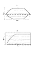
すなわち、図1に、本発明の電気二重層キャパシタと従来例の電気二重層キャパシタの充放電曲線を示すように、本発明の電気二重層キャパシタの充放電曲線を示す図1(A)においては、初回の充電時に定電流充電によって充電する際には、時間に対する電圧変化が、充電の初期においては時定数に基づく電圧変化率よりも電圧の変化率が大きく、電圧の上昇によって時定数に基づく電圧の変化率よりも変化率が小さくなる屈曲点C1を有しており、第2回目以降の充電の際にも、同様の挙動を示す屈曲点C2を有していることを特徴としている。 That is, in FIG. 1A, which shows the charge / discharge curves of the electric double layer capacitor of the present invention, as shown in FIG. 1, the charge / discharge curves of the electric double layer capacitor of the present invention and the conventional electric double layer capacitor are shown. When charging by constant current charging at the first charge, the voltage change with respect to time is larger than the voltage change rate based on the time constant in the initial stage of charging, and based on the time constant due to the voltage increase It has a bend point C1 where the change rate is smaller than the change rate of the voltage, and has a bend point C2 that exhibits the same behavior during the second and subsequent charging.
これに対して、特許文献1に記載のような黒鉛類似の微結晶炭素を有する炭素材料を用いて、電気二重層キャパシタを組み立てた後に、最初に定格電圧以上の電圧を分極性電極間に印加することによって、微結晶炭素の層間に有機電解液における溶質のイオンを挿入させて静電容量を発現させた炭素電極を用いた場合にも、図1(B)に示すように、初回の充電時には、初期の電圧上昇率は時定数に基づく電圧変化率よりも大きく、屈曲点D1を示すものの、第2回目の充電の際には、時定数に基づく充電曲線を示す点に相違点を有している。
初回の充電時の電圧変化曲線にみられる現象は、電気二重層キャパシタ中への細部への電解液の進入の駆動力および炭素中へのイオンの挿入による電流とみられ、第2回目以降の定電流による充電時の電圧変化曲線には屈曲点がみられない。
On the other hand, after assembling an electric double layer capacitor using a carbon material having microcrystalline carbon similar to graphite as described in
The phenomenon seen in the voltage change curve during the first charge is considered to be the driving force of the electrolyte entering the details into the electric double layer capacitor and the current due to the insertion of ions into the carbon. There is no inflection point in the voltage change curve during charging by current.
本発明の黒鉛電極にみられる現象は、充電時に毎回ある一定の電圧において電解液中から黒鉛へのイオンの吸着が開始され、その結果大きな静電容量が発現しているものと考えられる。またこの反応は、電解液が細部へ進入する駆動力も作用するので、初回の充電時に最も大きく進行するものとみられる。第2回目以降の充電時においても、初回の充電時に比べてその時間は短いものの同様の現象が見られる。 The phenomenon observed in the graphite electrode of the present invention is considered that the adsorption of ions from the electrolytic solution to the graphite is started at a certain voltage every time during charging, and as a result, a large capacitance is developed. This reaction is also considered to proceed most greatly during the first charge because the driving force for the electrolyte to enter the details also acts. Even during the second and subsequent charging, the same phenomenon is observed although the time is shorter than that during the first charging.
本発明の黒鉛電極は、活性炭や、初期充電によって細孔を形成した炭素を電極としたものに比べて、静電容量が大きいので、活性炭等の電極を対極とした場合には、活性炭等の電極に対応した静電容量を得るためには、黒鉛電極は活性炭等の電極に比べて厚みを大幅に薄くすることが可能となる。
その結果、黒鉛電極側の厚みを小さくすることによって従来の電気二重層キャパシタと同様の充放電速度を有し、従来のものに比べて容積が小さな電気二重層キャパシタを提供することができる。
Since the graphite electrode of the present invention has a larger capacitance than activated carbon or carbon having pores formed by initial charging as an electrode, when an electrode such as activated carbon is used as a counter electrode, activated carbon or the like In order to obtain a capacitance corresponding to the electrode, the graphite electrode can be made much thinner than an electrode such as activated carbon.
As a result, by reducing the thickness on the graphite electrode side, it is possible to provide an electric double layer capacitor having a charge / discharge rate similar to that of a conventional electric double layer capacitor and having a smaller volume than the conventional one.
本発明に適用可能な黒鉛を、ラマン分光法にて比較したところ、本発明に適用可能な黒鉛は、グラファイト層に乱れを生じている黒鉛であることが判明した。具体的には、ラマン分光法にて1580カイザーおよび1360カイザーのピークの比を計ることで、グラファイト層の乱れを定量化したものである。I(1360)/I(1580)の比が0.02から0.3の問にあり、好ましくは0.15付近にあるものである。
この比が0.02よりも小さいもの、あるいは0.3よりも大きなものでは十分な静電容量を得ることができない。
When the graphite applicable to the present invention was compared by Raman spectroscopy, it was found that the graphite applicable to the present invention was graphite in which the graphite layer was disturbed. Specifically, the disorder of the graphite layer is quantified by measuring the peak ratio of 1580 Kaiser and 1360 Kaiser by Raman spectroscopy. The ratio of I (1360) / I (1580) is in the range of 0.02 to 0.3, preferably in the vicinity of 0.15.
If this ratio is smaller than 0.02 or larger than 0.3, sufficient capacitance cannot be obtained.
また、X線回折法による測定においては、六方晶と菱面体晶の比が六方晶/菱面体の比(Ib/Ia)=0.3以上のものが最も好ましい。
この比が0.3よりも小さいものでは十分な静電容量を得ることができない。
In the measurement by the X-ray diffraction method, the hexagonal / rhombohedral ratio (Ib / Ia) = 0.3 or more is most preferable.
If this ratio is less than 0.3, sufficient capacitance cannot be obtained.
なお、これらの黒鉛で特に菱面体晶成分の少ない黒鉛をリチウムイオン電池の負極材料として使用することが既に提案されている。リチウムイオン電池用の負極材料である炭素材料は、リチウムの酸化還元電位を基準として+0.25V以下の電位においてリチウムの炭素材料中への挿入よって電池の負極としての特性を発現するものである。これに対して、本願の発明の電気二重層キャパシタにおいては、黒鉛電極の動作電位はリチウムの酸化還元電位を基準として、+0.5Vから+6Vの電位の範囲、好ましくは+0.5V〜+5.5V、より好ましくは+0.5V〜5.0Vであってリチウムイオン電池用の負極材料である炭素材料とは異なる領域において異なる動作をしているものと考えられる。
本発明の黒鉛電極においては、水素基準電極に対して−2.5V〜+3V、好ましくは−2.5V〜+2.5V、より好ましくは−2.5V〜+2.0Vの電位において特殊な電気二重層形成が起こると推測される。その結果、静電容量が発現するものとみられる。このように本発明の電気二重層キャパシタよりも、卑な電位の領域である−3Vよりも卑な電位領域において生じるリチウムの黒鉛層間への挿入を利用したリチウムイオン電池と、本発明の電気二重層キャパシタとはその動作電位領域、反応機構等も異なるものとみられる。
In addition, it has already been proposed to use graphite having a particularly small rhombohedral component as a negative electrode material for a lithium ion battery. A carbon material, which is a negative electrode material for a lithium ion battery, exhibits characteristics as a negative electrode of a battery by inserting lithium into the carbon material at a potential of +0.25 V or less with respect to the oxidation-reduction potential of lithium. On the other hand, in the electric double layer capacitor of the present invention, the operating potential of the graphite electrode is in the range of +0.5 V to +6 V, preferably +0.5 V to +5.5 V, based on the oxidation-reduction potential of lithium. More preferably, it is +0.5 V to 5.0 V, and is considered to operate differently in a different region from the carbon material which is a negative electrode material for a lithium ion battery.
In the graphite electrode of the present invention, a special electric voltage is applied at a potential of −2.5 V to +3 V, preferably −2.5 V to +2.5 V, more preferably −2.5 V to +2.0 V with respect to the hydrogen reference electrode. It is estimated that stratification occurs. As a result, it is considered that capacitance is developed. Thus, a lithium ion battery using insertion of lithium between graphite layers generated in a base potential region lower than −3 V, which is a base potential region, as compared with the electric double layer capacitor of the present invention, and the electric double layer of the present invention. It seems that the operating potential region, reaction mechanism, and the like are different from those of the multilayer capacitor.
更に、本発明に好ましい特徴は、粒径:1μm〜20μm、層間間隔:0.3354〜0.3390nm、Lc:50〜100nmである。 Further, preferred features of the present invention are a particle size of 1 μm to 20 μm, an interlayer spacing: 0.3354 to 0.3390 nm, and Lc: 50 to 100 nm.
また、一方の電極として、黒鉛以外の炭素材料を用いる場合には、石油ピッチ石油コークス等の石油系炭素原料、石炭ピッチ、石炭コークス等の石炭系炭素原料、ヤシガラ、オガクズ等の木質系炭素原料、フェノール樹脂、ポリ塩化ビニルポリ塩化ビニリデン、ポリイミド等の樹脂系炭素原料等を原料として、アルカリ金属とアルカリ金属化合物の少なくとも1種と共にアルカリ金属の蒸気が発生する温度以上で熱処理を行って製造される黒鉛類似の微結晶炭素を有する炭素材料を挙げることができ、得られた電極は初期充電時における通電によって賦活されて電気二重層キャパシタとしての静電容量を発現する。また表面積1000平方メートル/gから3000平方メートル/gの活性炭を用いることができる。 When carbon materials other than graphite are used as one electrode, petroleum-based carbon materials such as petroleum pitch petroleum coke, coal-based carbon materials such as coal pitch and coal coke, woody carbon materials such as coconut shells and sawdust It is manufactured by using a resin-based carbon raw material such as phenol resin, polyvinyl chloride, polyvinylidene chloride, polyimide, etc. as a raw material and performing heat treatment at a temperature higher than the temperature at which alkali metal vapor is generated together with at least one of alkali metal and alkali metal compound. A carbon material having microcrystalline carbon similar to graphite can be mentioned, and the obtained electrode is activated by energization at the time of initial charging and develops a capacitance as an electric double layer capacitor. Activated carbon having a surface area of 1000 square meters / g to 3000 square meters / g can be used.
また本発明の黒鉛電極の対極として、リチウム金属、表面積10平方メートル以下の黒鉛、あるいは金属酸化物などリチウムイオンのインターカレーションが可能な物質を負極に用い、リチウムイオンを含有する有機電解液を用いてもよい。 In addition, as the counter electrode of the graphite electrode of the present invention, lithium metal, graphite having a surface area of 10 square meters or less, or a material capable of lithium ion intercalation such as metal oxide is used for the negative electrode, and an organic electrolyte containing lithium ions is used. May be.
本発明において使用することができる電解液は、非水溶媒中に溶質を溶解させたものを用いることができる。特に、電解液としては、分子の最小投影面における原子間距離が0.7nm以下のイオンを含有するものが炭素材料の中に挿入されて電気二重層キャパシタの電気容量を大きなものとすることができるので好ましい。
すなわち、電解液において作用する陰イオンとしては、4フッ化ホウ酸イオン(BF4 -)、6フッ化リン酸イオン(PF6 -)、過塩素酸イオン(ClO4 -)、6フッ化ヒ素(AsF6 -)、6フッ化アンチモン(SbF6 -)、ペルフルオロメチルスルホニル(CF3SO2 -)、ペルフルオロメチルスルホナト(CF3SO3 - )からなる群から選ばれる少なくとも一種を挙げることができる。
As the electrolytic solution that can be used in the present invention, a solution in which a solute is dissolved in a non-aqueous solvent can be used. In particular, as the electrolytic solution, an electrolyte containing ions having an interatomic distance of 0.7 nm or less on the minimum projected surface of the molecule may be inserted into the carbon material to increase the electric capacity of the electric double layer capacitor. It is preferable because it is possible.
That is, the anions acting in the electrolyte include tetrafluoroborate ion (BF 4 − ), hexafluorophosphate ion (PF 6 − ), perchlorate ion (ClO 4 − ), and arsenic hexafluoride. And at least one selected from the group consisting of (AsF 6 − ), antimony hexafluoride (SbF 6 − ), perfluoromethylsulfonyl (CF 3 SO 2 − ), and perfluoromethyl sulfonate (CF 3 SO 3 − ). it can.
また、陽イオンとしては、対称、非対称の四級アンモニウムイオン、エチルメチルイミダゾリウム、スピロ−(1,1’)ビピロリジニウム等のイミダゾリウム誘導体イオン、リチウムイオンからなる群から選ばれる。なかでも、トリエチルメチルアンモニウムイオン、上記ピロリジニウム化合物、スピロ−(1,1’)ビピロリジニウム、ジメチルピロリジニウム、ジエチルピロリジニウム、エチルメチルピロリジニウム、スピロ−ビピリジニウム、テトラメチルホスホニウム、テトラエチルホスホニウム、トリメチルアルキルアンモニウムであってアルキル基の炭素数が2から10であるアンモニウムからなる群から選ばれる少なくともいずれか一種等を挙げることができる。これらの分子は、最小投影面積が小さく、炭素材料の層間に挿入されて大きな容量を発現する。 The cation is selected from the group consisting of symmetrical and asymmetrical quaternary ammonium ions, imidazolium derivative ions such as ethylmethylimidazolium, spiro- (1,1 ') bipyrrolidinium, and lithium ions. Among them, triethylmethylammonium ion, the above pyrrolidinium compound, spiro- (1,1 ′) bipyrrolidinium, dimethylpyrrolidinium, diethylpyrrolidinium, ethylmethylpyrrolidinium, spiro-bipyridinium, tetramethylphosphonium, tetraethylphosphonium, trimethyl Examples thereof include at least any one selected from the group consisting of ammonium which is alkylammonium and whose alkyl group has 2 to 10 carbon atoms. These molecules have a small minimum projected area and are inserted between carbon material layers to develop a large capacity.
また、非水溶媒としては、テトラヒドロフラン(THF)、メチルテトラヒドロフラン(MeTHF)、メチルホルムアミド、メチルアセテート、ジエチルカーボネート、ジメチルエーテル(DME)、プロピレンカーボネート(PC)、γ−ブチルラクトン(GBL)、ジメチルカーボネート(DMC)、エチレンカーボネート(EC)、アセトニトリル(AN)、スルホラン(SL)あるいは分子の一部にハロゲンを含有するこれら非水溶媒からなる群から選ばれる少なくとも1種を選ぶことができる。 Non-aqueous solvents include tetrahydrofuran (THF), methyltetrahydrofuran (MeTHF), methylformamide, methyl acetate, diethyl carbonate, dimethyl ether (DME), propylene carbonate (PC), γ-butyllactone (GBL), dimethyl carbonate ( DMC), ethylene carbonate (EC), acetonitrile (AN), sulfolane (SL), or at least one selected from the group consisting of these non-aqueous solvents containing a halogen in a part of the molecule can be selected.
また水素標準電位に対して正極側1.5V程度、陰極側では−1.6V程度で特殊な電気二重層形成が起こると推測されるために、溶媒、溶質ともに−1.6Vから+1.5V以上の電位窓を持つ必要があり、アニオンとしては4フッ化ホウ酸イオン(BF4 -)、6フッ化リン酸イオン(PF6 -)、過塩素酸イオン(ClO4 -)が好ましい。
また、カチオンとしては、上記ピロリジニウム化合物、スピロ−(1,1’)ビピロリジニウム、ジメチルピロリジニウム、ジエチルピロリジニウム、エチルメチルピロリジニウム、スピロ−ビピリジニウム等のピロリジニウム塩、テトラメチルホスホニウム、テトラエチルホスホニウムが好ましい。溶媒としては、−3Vから+3.5V程度の電位窓を持つ、アセトニトリル(AN)、プロピレンカーボネート(PC)、エチレンカーボネート(EC)、ジメチルカーボネート(DMC)の少なくとも一種からなるものが好ましい。
In addition, since it is estimated that a special electric double layer is formed at about 1.5V on the positive electrode side and about -1.6V on the cathode side with respect to the hydrogen standard potential, both the solvent and the solute are from -1.6V to + 1.5V. It is necessary to have the above potential window, and as the anion, tetrafluoroborate ion (BF 4 − ), hexafluorophosphate ion (PF 6 − ), and perchlorate ion (ClO 4 − ) are preferable.
Examples of the cation include pyrrolidinium compounds, spiro- (1,1 ′) bipyrrolidinium, dimethylpyrrolidinium, diethylpyrrolidinium, ethylmethylpyrrolidinium, pyrrolidinium salts such as spiro-bipyridinium, tetramethylphosphonium, tetraethylphosphonium. Is preferred. The solvent is preferably made of at least one of acetonitrile (AN), propylene carbonate (PC), ethylene carbonate (EC), and dimethyl carbonate (DMC) having a potential window of about -3V to + 3.5V.
電解液には、リチウムの酸化還元電位に対して+1Vから+5Vの範囲で分解し、黒鉛電極表面にイオン透過性の皮膜を形成する添加剤を含有させてもよい。また、初回の電圧印加時に、30℃から100℃の温度雰囲気において充電をしても良い。
以下に、実施例、比較例を示し本発明を説明する。
The electrolytic solution may contain an additive that decomposes in the range of +1 V to +5 V with respect to the oxidation-reduction potential of lithium and forms an ion-permeable film on the surface of the graphite electrode. Further, charging may be performed in a temperature atmosphere of 30 ° C. to 100 ° C. at the first voltage application.
The present invention will be described below with reference to examples and comparative examples.
(黒鉛電極1の製造)
表1の黒鉛1のように、ラマン比0.11、菱面体晶比0.56であり、個数平均粒径:3.5μm、層間間隔:0.3355nm、Lc:80nm、炭素以外の元素として、Fe:72ppm、Si:62ppm、Ca:32ppm、S:23ppm、Al:2ppm)なる特徴を有する黒鉛3g、アセチレンブラック(電気化学工業製)1g、ポリテトラフルオロエチレン粉末(三井・デュポンフロロケミカル製)0.3gを混合し、めのう乳鉢を用いて混練した後に成形装置を用いて、0.2mmの均一な厚みのシート状に成形して、黒鉛電極1を得た。また、密度は0.8g/ccであった。
(Manufacture of graphite electrode 1)
Like
(黒鉛電極2の製造)
黒鉛電極1の製造における黒鉛に代えて、表1の黒鉛2のように、ラマン比0.05、菱面体晶比0であり、平均粒径:3.0μm、層間間隔:0.354nm、比表面積13m2/g、を用いた点を除き、黒鉛電極の製造1と同様にして黒鉛電極2を製造した。
(黒鉛電極3の製造)
黒鉛電極1の製造における黒鉛に代えて、黒鉛として、表1の黒鉛3のように、ラマン比0.06、菱面体晶比0.53であり、平均粒径:3.0μm、層間間隔:0.354nm、比表面積5m2/gを用いた点を除き、黒鉛電極の製造1と同様にして黒鉛電極3を製造した。
(Manufacture of graphite electrode 2)
Instead of graphite in the production of the
(Production of graphite electrode 3)
Instead of graphite in the production of the
(黒鉛電極4の製造)
黒鉛電極1の製造における黒鉛に代えて、表1の黒鉛4のように、ラマン比0.05、菱面体晶比0であり平均粒径:3.0μm、層間間隔:0.354nm、比表面積15m2 /g、を用いた点を除き、黒鉛電極の製造1と同様にして黒鉛電極4を製造した。
(黒鉛電極5の製造)
黒鉛電極1の製造における黒鉛に代えて、表1の黒鉛5のように、ラマン比0.05、菱面体晶比0であり平均粒径:2.5μm、層間間隔:0.355nm、比表面積5m2/g、を用いた点を除き、黒鉛電極の製造1と同様にして黒鉛電極5を製造した。
(Production of graphite electrode 4)
Instead of graphite in the production of the
(Production of graphite electrode 5)
Instead of graphite in the production of the
(黒鉛電極6の製造)
黒鉛電極1の製造における黒鉛に代えて、表1の黒鉛6のように、ラマン比0.19、菱面体晶比0.33であり、平均粒径0.5μm、比表面積300m2/gを用いた点を除き、黒鉛電極の製造1と同様にして黒鉛電極6を製造した。
(黒鉛電極7の製造)
黒鉛電極1の製造における黒鉛に代えて、メソフィーズカーボンMCMBを2800℃で15時間焼成した表1の黒鉛7のように、ラマン比0.16、菱面体晶比0である、平均粒径5μm、比表面積15m2/gの炭素を用いた点を除き黒鉛電極の製造1と同様にして黒鉛電極7を製造した。
(Manufacture of graphite electrode 6)
Instead of graphite in the production of the
(Manufacture of graphite electrode 7)
Instead of graphite in the production of the
(黒鉛電極8の製造)
黒鉛電極1の製造における黒鉛に代えて、表1の黒鉛8のように、ラマン比0.26、菱面体晶比0.31であり、平均粒径3μm、比表面積80m2/gを用いた点を除き、黒鉛電極の製造1と同様にして黒鉛電極8を製造した。
(黒鉛電極9の製造)
黒鉛電極1の製造における黒鉛に代えて、表1の黒鉛9のように、ラマン比0.03、菱面体晶比0.19であり、平均粒径5μm、比表面積12m2/gを用いた点を除き、黒鉛電極の製造1と同様にして黒鉛電極8を製造した。
(Manufacture of graphite electrode 8)
In place of graphite in the production of the
(Production of graphite electrode 9)
Instead of graphite in the production of the
(金属リチウム対極による充放電の結果)
負極としてリチウム金属を用い、正極として表1の黒鉛1を用い、電解液に0.8MLiPF6のEC/DMC溶液を用いて0.5mAの定電流充放電を行ったところ、図7のような充放電曲線を得た。黒鉛1は対リチウム金属に対して4.5V付近から急激に容量を発現し、4.8V付近で25mAh/g程度の電気容量を得た。すなわち、金属リチウムの酸化還元電位に対して1V以上の電圧において、10〜200mAhの電気エネルギー貯蔵能力を有するBET表面積5〜300m2/gの黒鉛、および該黒鉛を用いることを特徴とする蓄電要素が見出された。好ましくは、上記黒鉛は金属リチウムの酸化還元電位に対して3〜6Vの電圧において10〜150mAhの電気エネルギー貯蔵能力、及びBET表面積10〜250m2/gを有する。
(Results of charging / discharging with metallic lithium counter electrode)
When lithium metal was used as the negative electrode,
(黒鉛の分析結果)
黒鉛電極に用いた黒鉛をラマン分光装置(ジョバンイボン社製 分光器500M,検出器Specrum ONE、ソフトSpectra MAX)を用い顕微鏡(オリンパス社製 BX60M)を備えた顕微ユニット(西進商事製)を取り付け、レーザー照射装置(日本電気製 Ar-Laser GLG3280)を用い測定した。特に1580および1360カイザー付近のピークを測定するとともに、黒鉛由来の1580cm-1のピークの半値幅をcm-1の単位で求めた。
(Results of graphite analysis)
A graphite unit (manufactured by Nishijin Shoji Co., Ltd.) equipped with a microscope (Olympus BX60M) using a Raman spectrometer (Spectrograph 500M manufactured by Joban Yvon, detector Spectrum ONE, Soft Spectra MAX) is used for the graphite electrode. It measured using the laser irradiation apparatus (NEC Ar-Laser GLG3280). With particular measuring the peak of 1580 and 1360 near the Kaiser, the half-value width of the peak of the graphite from the 1580 cm -1 was determined in units of cm -1.
また、これらの黒鉛をX線回折装置(理学電機製RINT2000)にて測定した。
結晶性は2θ=26.5°付近の六方晶(002)ピークの半値幅が1°以内を良とした。
結晶化度は結晶化度=(3.44−d(002))/0.0868の式から計算した。d(002)は2θ=26.5°付近のピーク位置から面間隔d(002)を求めた。
菱面体晶(101)のピーク位置は2θ=43.3°付近でピーク強度をIBとする。六方晶(100)のピーク位置は2θ=42.4°付近に有り、ピーク強度をIAすると、ピーク強度比IB/IAを強度比とした。
These graphites were measured with an X-ray diffractometer (RINT2000 manufactured by Rigaku Corporation).
The crystallinity was good when the half width of the hexagonal crystal (002) peak near 2θ = 26.5 ° was within 1 °.
The crystallinity was calculated from the formula: crystallinity = (3.44−d (002)) / 0.0868. For d (002), the interplanar spacing d (002) was obtained from the peak position near 2θ = 26.5 °.
The peak position of the rhombohedral crystal (101) is around 2θ = 43.3 °, and the peak intensity is IB. The peak position of hexagonal crystal (100) is in the vicinity of 2θ = 42.4 °, and when the peak intensity is IA, the peak intensity ratio IB / IA is taken as the intensity ratio.
六方晶(101)は2θ=44.5°付近にある。菱面体晶(101)のピーク2θ=43.3°付近が平坦か凹の場合は菱面体晶は無し、かすかに認められるのを痕跡とした。
また、比表面積は比表面積測定装置(島津製作所製Gemini2375)によりBET比表面積を求めた。また、平均粒径は粒度分布測定装置(堀場製作所製 遠心式自動粒度分布測定装置 CAPA−300)によって行った。
以上の結果を表1に示す。
The hexagonal crystal (101) is in the vicinity of 2θ = 44.5 °. In the case where the vicinity of the peak 2θ = 43.3 ° of the rhombohedral crystal (101) is flat or concave, there was no rhombohedral crystal, and it was traced that it was slightly recognized.
Moreover, the specific surface area calculated | required the BET specific surface area with the specific surface area measuring apparatus (Shimadzu Corporation Gemini2375). Moreover, the average particle diameter was measured with the particle size distribution measuring apparatus (Horiba Manufacturing Centrifugal automatic particle size distribution measuring apparatus CAPA-300).
The results are shown in Table 1.
[表1]
表において、ラマン比は、1580カイザーおよび1360カイザーの強度比I(1360)/I(1580)を示す。 In the table, the Raman ratio indicates the intensity ratio I (1360) / I (1580) of 1580 Kaiser and 1360 Kaiser.
(分極性炭素電極1の製造)
活性炭(関西熱化学製MSP−20)を3g、アセチレンブラック(電気化学工業製)1g、ポリテトラフルオロエチレン粉末(三井・デュポンフロロケミカル製)0.3gを混合し、めのう乳鉢を用いて混練した後に成形装置を用いて、0.2mmの均一な厚みのシート状に成形して、分極性炭素電極1を得た。また、密度は0.8g/ccであった。なお、表においては活性炭1と表記した。
(Production of polarizable carbon electrode 1)
3 g of activated carbon (MSP-20 manufactured by Kansai Thermal Chemical Co., Ltd.), 1 g of acetylene black (manufactured by Denki Kagaku Kogyo), and 0.3 g of polytetrafluoroethylene powder (manufactured by Mitsui / DuPont Fluorochemical) were mixed and kneaded using an agate mortar. Later, by using a molding apparatus, the sheet was molded into a sheet having a uniform thickness of 0.2 mm to obtain a
(分極性炭素電極2の製造)
電極の厚みを0.8mmとした点を除き活性炭電極1と同様にして分極性炭素電極2を得た。なお、表においては活性炭2と表記した。
(Production of polarizable carbon electrode 2)
A
(分極性炭素電極3の製造)
電極の厚みを1.0mmとした点を除き活性炭電極1と同様にして分極性炭素電極3を得た。なお、表においては活性炭3と表記した。
(Production of polarizable carbon electrode 3)
A
(分極性炭素電極4の製造)
電極の厚みを1.2mmとした点を除き活性炭電極1と同様にして分極性炭素電極4を得た。なお、表においては活性炭4と表記した。
(Manufacture of polarizable carbon electrode 4)
A
(非多孔性炭素電極1の製造)
ニードルコークス(新日鉄化学製)を、窒素気流中で1000℃において5時間焼成した。次に、この3倍量の水酸化カリウムと混合し、同じく窒素気流中で750℃で5時間焼成して賦活した。
これを洗浄し、BET法にて窒素の吸着等温曲線により表面積を求めたところ80m2/g であった。これは通常の活性炭表面積の1/20程度の非多孔性炭素であった。
得られた非多孔性炭素:3g、アセチレンブラック(電気化学工業製)1g、ポリテトラフルオロエチレン粉末(三井・デュポンフロロケミカル製)0.3gを混合し、めのう乳鉢を用いて混練した後に成形装置を用いて、0.2mmの均一な厚みのシート状に成形して、非多孔性炭素電極1を得た。また、密度は0.8g/ccであった。なお、表においては、非多孔1と表記する。
(Manufacture of non-porous carbon electrode 1)
Needle coke (manufactured by Nippon Steel Chemical Co., Ltd.) was fired at 1000 ° C. for 5 hours in a nitrogen stream. Next, the mixture was mixed with 3 times the amount of potassium hydroxide and activated by calcination at 750 ° C. for 5 hours in the same nitrogen stream.
This was washed, and the surface area was determined by the nitrogen adsorption isotherm curve by the BET method. As a result, it was 80 m 2 / g. This was non-porous carbon about 1/20 of the normal activated carbon surface area.
Non-porous carbon obtained: 3 g, 1 g of acetylene black (manufactured by Denki Kagaku Kogyo), 0.3 g of polytetrafluoroethylene powder (manufactured by Mitsui / DuPont Fluorochemical) are mixed and kneaded using an agate mortar and then a molding apparatus. Was used to form a sheet with a uniform thickness of 0.2 mm to obtain a
(非多孔性炭素電極2の製造)
電極の厚みを0.8mmとした点を除き非多孔性炭素電極1と同様にして非多孔性炭素電極2を得た。なお、表においては、非多孔2と表記する。
(Production of non-porous carbon electrode 2)
A
(非多孔性炭素電極3の製造)
電極の厚みを1.0mmとした点を除き非多孔性炭素電極1と同様にして非多孔性炭素電極3を得た。なお、表においては、非多孔3と表記する。
(Manufacture of non-porous carbon electrode 3)
A
(非多孔性炭素電極4の製造)
電極の厚みを1.2mmとした点を除き非多孔性炭素電極1と同様にして非多孔性炭素電極4を得た。なお、表においては、非多孔4と表記する。
(Production of non-porous carbon electrode 4)
A
(非多孔性炭素電極5の製造)
電極の厚みを0.4mmとした点を除き非多孔性炭素電極1と同様にして非多孔性炭素電極5を得た。なお、表においては、非多孔5と表記する。
(Manufacture of non-porous carbon electrode 5)
A
(試験用のセルの作製)
先に製造した黒鉛電極1〜8、活性炭電極1〜4、非多孔性炭素電極1〜5をそれぞれ直径20mmの大きさに切り出し、セパレータ(日本高度紙製 MER3−5)を介して、表2に示される組み合わせに従い、図2に斜視図を示す参照電極を設けた3電極からなる試験用セルを組み立てた。
(Production of test cell)
The
図2において、試験用セル1は、セル本体2、底部カバー3、上部カバー4からなり、絶縁性部材から形成されたOリング5を介して、保持部材6と、絶縁性ワッシャー7によって一体に組み立てられている。
セル本体2と底部カバー3との間には、活性炭電極等から構成された参照電極8が、ステンレス、アルミニウム等の金属からなる多孔性の押さえ板9によって保持されて集電されている。
また、セル本体2と上部カバー4との間には、絶縁性部材からなる保持ガイド10に設けた開口部に正極集電体11、正極電極12を装着し、正極電極上にはセパレータ13を介して、負極電極14および負極集電体15配置し、電解液を注液した後にばね16によって押圧した状態で密閉したものであって、セル本体、底部カバー、および上部カバーのそれぞれ各構成部材が正極、参照電極、負極に結合されたものであり、密閉状態を保持した状態での電気二重層キャパシタの充放電試験を可能としたものである。
In FIG. 2, the
Between the
Further, between the
(充放電試験)
得られた試験セルに対して、5mAの定電流で充電電流を印加した後に、3.2Vに達した時点で定電圧に切換て、計2時間の充電を行った後、5mA2Vまで放電し試験セルの静電容量および単位体積当たりの静電容量を測定し、それぞれセル容量(単位F)、単位体積容量(F/cm3)として表2に示した。
また、充放電時には、端子電圧と共に参照電極を基準として、標準水素電位基準の正極電位および負極電位を測定した。
(Charge / discharge test)
After applying a charging current at a constant current of 5 mA to the obtained test cell, switching to a constant voltage when reaching 3.2 V, charging for a total of 2 hours, discharging to 5 mA and 2 V, and testing measuring the capacitance of the electrostatic capacity and per unit volume of the cell, respectively cell capacity (unit F), are shown in Table 2 as a unit volumetric capacity (F / cm 3).
Further, at the time of charging and discharging, the positive electrode potential and the negative electrode potential of the standard hydrogen potential standard were measured with the reference voltage as a reference together with the terminal voltage.
[表2]
[表2]の続き
ただし、表2において、
TEMABF4/PC:1.5M/Lのトリエチルメチルアンモニウムの4フッ化ホウ酸塩を含有したプロピレンカーボネート溶液
TEMAPF6/PC:1.5M/Lのトリエチルメチルアンモニウムの6フッ化リン酸塩を含有したプロピレンカーボネート溶液
SBPBF4/PC:1.5M/Lのスピロ−(1,1’)ビピロリジニウムの4フッ化ホウ酸塩を含有したプロピレンカーボネート溶液
SBPPF6/PC:1.5M/Lのスピロ−(1,1’)ビピロリジニウムの6フッ化リン酸を含有したプロピレンカーボネート溶液
DMPBF4/PC:1.5M/Lのジメチルピロリジニウムの4フッ化ホウ酸塩を含有したプロピレンカーボネート溶液
DEPBF4/PC:1.5M/Lのジエチルピロリジニウムの4フッ化ホウ酸塩を含有したプロピレンカーボネート溶液
DEMPBF4/PC:1.5M/Lのエチルメチルピロリジニウムの4フッ化ホウ酸塩を含有したプロピレンカーボネート溶液
DMP1BF4/PC:1.0M/Lのジメチルピロリジニウムの4フッ化ホウ酸塩を含有したプロピレンカーボネート溶液
DEP1BF4/PC:1.0M/Lのジエチルピロリジニウムの4フッ化ホウ酸塩を含有したプロピレンカーボネート溶液
EMP1BF4/PC:1.0M/Lのエチルメチルピロリジニウムの4フッ化ホウ酸塩を含有したプロピレンカーボネート溶液
SBPi1BF4/PC:1.0M/Lのスピロ−ビピリジニウムの4フッ化ホウ酸塩を含有したプロピレンカーボネート溶液
TMPBF4/PC:0.8M/Lのテトラメチルホスホニウムの4フッ化ホウ酸塩を含有したプロピレンカーボネート溶液
TEPBF4/PC:0.8M/Lのテトラエチルホスホニウムの4フッ化ホウ酸塩を含有したプロピレンカーボネート溶液
LiPF6/PC:0.8M/Lの6フッ化リン酸のリチウム塩を含有したプロピレンカーボネート溶液
EMIBF4/PC:1.5M/Lのエチルメチルイミダゾリウムを含有したプロピレンカーボネート溶液
TMPABF4/PC:0.8M/Lのトリメチルペンチルアンモニウムの4フッ化ホウ酸塩を含有したプロピレンカーボネート溶液
TMOABF4/PC:0.8M/Lのトリメチルオクチルアンモニウムの4フッ化ホウ酸塩を含有したプロピレンカーボネート溶液
However, in Table 2,
TEMABF4 / PC: Propylene carbonate solution containing 1.5M / L triethylmethylammonium tetrafluoroborate
TEMAPF6 / PC: Propylene carbonate solution containing 1.5M / L triethylmethylammonium hexafluorophosphate
SBPBF4 / PC: propylene carbonate solution containing 1.5 M / L of spiro- (1,1 ′) bipyrrolidinium tetrafluoroborate
SBPPF6 / PC: Propylene carbonate solution containing 1.5 M / L spiro- (1,1 ′) bipyrrolidinium hexafluorophosphate
DMPBF4 / PC: Propylene carbonate solution containing 1.5M / L dimethylpyrrolidinium tetrafluoroborate
DEPBF4 / PC: Propylene carbonate solution containing 1.5M / L diethylpyrrolidinium tetrafluoroborate
DEMPBF4 / PC: Propylene carbonate solution containing 1.5M / L of ethylmethylpyrrolidinium tetrafluoroborate
DMP1BF4 / PC: Propylene carbonate solution containing 1.0 M / L dimethylpyrrolidinium tetrafluoroborate
DEP1BF4 / PC: Propylene carbonate solution containing 1.0 M / L diethylpyrrolidinium tetrafluoroborate
EMP1BF4 / PC: Propylene carbonate solution containing 1.0 M / L of ethylmethylpyrrolidinium tetrafluoroborate
SBPi1BF4 / PC: A propylene carbonate solution containing 1.0 M / L of spiro-bipyridinium tetrafluoroborate
TMPBF4 / PC: Propylene carbonate solution containing tetramethylphosphonium tetrafluoroborate at 0.8M / L
TEPBF4 / PC: Propylene carbonate solution containing 0.8M / L tetraethylphosphonium tetrafluoroborate
LiPF6 / PC: Propylene carbonate solution containing 0.8M / L lithium hexafluorophosphate
EMIBF4 / PC: Propylene carbonate solution containing 1.5M / L ethylmethylimidazolium
TMPABF4 / PC: Propylene carbonate solution containing 0.8M / L trimethylpentylammonium tetrafluoroborate
TMOABF4 / PC: Propylene carbonate solution containing 0.8M / L trimethyloctylammonium tetrafluoroborate
(充放電曲線の挙動1)
図3は、本発明の黒鉛を正極に用いたセル番号1−1についての、2回目の充放電時の充放電曲線を示す図であり、図3(A)は、参照電極を用いて測定した標準水素電極基準の正極側、負極側の電位を測定した図であり、図3(B)は、端子電圧を測定した場合の電圧を充電開始時のみを示した図である。
電圧曲線は、端子電圧が2.1V付近において、充電側には顕著な屈曲点を観測することができ、屈曲点を境に電圧の時間に対する傾きが大きく変化している。
(Behavior of charge / discharge curve 1)
FIG. 3 is a view showing a charge / discharge curve at the second charge / discharge for cell number 1-1 using the graphite of the present invention for the positive electrode, and FIG. 3 (A) is measured using a reference electrode. FIG. 3B is a diagram showing only the voltage when the terminal voltage is measured at the start of charging. FIG.
In the voltage curve, when the terminal voltage is around 2.1 V, a remarkable inflection point can be observed on the charging side, and the slope of the voltage with respect to time changes greatly at the inflection point.
図4は、本発明の黒鉛を正極に用いたセル番号7−2についての、2回目の充放電時の充放電曲線を示す図であり、図4(A)は、参照電極を用いて測定した標準水素電極基準の正極側、負極側の電位を測定した図であり、図4(B)は、端子電圧を測定した場合の電圧を充電開始時のみを示した図である。
電圧曲線は、端子電圧が2.2V付近において、充電側、放電側共に顕著な屈曲点を観測することができ、屈曲点を境に電圧の時間に対する傾きが大きく変化している。
FIG. 4 is a view showing a charge / discharge curve at the second charge / discharge for cell number 7-2 using the graphite of the present invention for the positive electrode, and FIG. 4 (A) is measured using the reference electrode. FIG. 4B is a diagram showing only the voltage when the terminal voltage is measured at the start of charging. FIG.
In the voltage curve, when the terminal voltage is around 2.2 V, a remarkable inflection point can be observed on both the charging side and the discharging side, and the slope of the voltage with respect to time changes greatly at the inflection point.
図5は、本発明の黒鉛を負極に用いたセル番号8−3についての、2回目の充放電時の充放電曲線を示す図であり、図5(A)は、参照電極を用いて測定した標準水素電極基準の正極側、負極側の電位を個別に測定した図であり、図5(B)は、端子電圧を測定した場合の電圧を充電開始時のみを示した図である。
電圧曲線は、端子電圧が2.3V付近において、充電側、放電側共に顕著な屈曲点を観測することができ、屈曲点を境に電圧の時間に対する傾きが大きく変化している。
FIG. 5 is a diagram showing a charge / discharge curve at the second charge / discharge for cell number 8-3 using the graphite of the present invention as a negative electrode, and FIG. 5 (A) is measured using a reference electrode. FIG. 5B is a diagram showing the voltage when the terminal voltage is measured only at the start of charging. FIG.
In the voltage curve, a remarkable inflection point can be observed on the charge side and the discharge side when the terminal voltage is around 2.3 V, and the slope of the voltage with respect to time changes greatly at the inflection point.
(充放電曲線の挙動2)
図6は、先行技術1に記載の電気二重層キャパシタと同様の構成の比較例を示すセル番号10−1についての、2回目の充放電時の充放電曲線を示す図である。
正極、負極とも初回の充電時に静電容量を発現する非多孔性炭素電極を用いたものであり、図6(A)は、参照電極を用いて測定した標準水素電極基準の正極側、負極側の電位を個別に測定した図であり、図6(B)は、端子電圧を測定した場合の電圧を充電開始時のみを拡大して示した図である。
いずれにおいても、時間に対する電圧変化曲線には屈曲点は観察されなかった。
(Charge / discharge curve behavior 2)
FIG. 6 is a diagram showing a charge / discharge curve at the time of second charge / discharge for cell number 10-1 showing a comparative example having the same configuration as the electric double layer capacitor described in
Both the positive electrode and the negative electrode are non-porous carbon electrodes that develop a capacitance during the initial charge. FIG. 6A shows the positive electrode side and the negative electrode side of the standard hydrogen electrode standard measured using the reference electrode. FIG. 6B is an enlarged view of the voltage when the terminal voltage is measured only at the start of charging.
In any case, no inflection point was observed in the voltage change curve with respect to time.
(黒鉛−黒鉛電極の系について)
本発明による黒鉛を正極、負極に用いた試験セル1−1では、水素の酸化還元電位を基準として吸着の起こる電位は正極側1.6V、負極側は−1.8Vであり、セル容量は80F/g程度と電気二重層キャパシタとしては驚異的な高容量となった。
これは本発明の黒鉛では、充電時に特殊な電気二重層を形成すると見られるため、大きな静電容量が発現したものとみられる。
一方、充電時にカチオンが吸着されなかったものとみられる1−2〜2−5の試験セルでは実用的な容量の発現はみられなかった。黒鉛電極2〜5を正極とし、活性炭電極とを組み合わせた場合にも、正極側の黒鉛電極において充分な容量が発現しなかった。
(Graphite-graphite electrode system)
In the test cell 1-1 in which graphite according to the present invention is used for the positive electrode and the negative electrode, the potential at which adsorption occurs based on the oxidation-reduction potential of hydrogen is 1.6 V on the positive electrode side and -1.8 V on the negative electrode side, and the cell capacity is About 80 F / g, the electric double layer capacitor has a surprisingly high capacity.
This is because the graphite of the present invention seems to form a special electric double layer during charging, and thus appears to have developed a large capacitance.
On the other hand, expression of practical capacity was not observed in the test cells of 1-2 to 2-5, in which it was considered that cations were not adsorbed during charging. Even when the
負極を黒鉛とし、電解液にはトリエチルメチルアンモニウムを用いた場合には十分な容量が発現せず、スピロ−(1,1’)ビピロリジニウムとした場合には容量が発現した。
そこで両者の分子モデルを作成するとともに、分子軌道計算を行って両者の違いを検討した。
When graphite was used as the negative electrode and triethylmethylammonium was used as the electrolytic solution, sufficient capacity was not developed, and when spiro- (1,1 ′) bipyrrolidinium was used, capacity was developed.
Therefore, both molecular models were created and molecular orbital calculations were performed to examine the differences between the two.
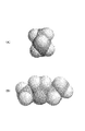
図8は、スピロ−(1,1’)ビピロリジニウム、トリエチルメチルアンモニウムの分子モデルの紙面方向へ投影した面積が最小となるとなる最小投影面を説明する図である。
図8(A)は、スピロ−(1,1’)ビピロリジニウム、図8(B)は、トリエチルメチルアンモニウムを示す。
また、図9は、スピロ−(1,1’)ビピロリジニウム、トリエチルメチルアンモニウムの分子モデルの紙面方向へ投影した面積が最大となるとなる最大投影面を説明する図である。
図9(A)は、スピロ−(1,1’)ビピロリジニウム、図9(B)は、トリエチルメチルアンモニウムを示す。
それぞれの縦と横の立体原子間距離を算出したところ、スピロ−(1,1’)ビピロリジニウムがそれぞれ0.4216nmおよび0.4212nmであり、トリエチルメチルアンモニウムが0.6137nmおよび0.4239nmであった。
これらのことから、トリエチルメチルアンモニウムにおける0.6nmを超える部位の立体障害が容量の出現に影響を与えているものと推測される。
FIG. 8 is a diagram for explaining the minimum projection plane that minimizes the area projected in the paper plane direction of the molecular model of spiro- (1,1 ′) bipyrrolidinium and triethylmethylammonium.
FIG. 8A shows spiro- (1,1 ′) bipyrrolidinium, and FIG. 8B shows triethylmethylammonium.
FIG. 9 is a diagram for explaining the maximum projection plane where the area projected in the paper plane direction of the molecular model of spiro- (1,1 ′) bipyrrolidinium and triethylmethylammonium is maximized.
FIG. 9A shows spiro- (1,1 ′) bipyrrolidinium, and FIG. 9B shows triethylmethylammonium.
When the distance between the vertical and horizontal stereo atoms was calculated, spiro- (1,1 ′) bipyrrolidinium was 0.4216 nm and 0.4212 nm, and triethylmethylammonium was 0.6137 nm and 0.4239 nm, respectively. .
From these facts, it is presumed that the steric hindrance at a site exceeding 0.6 nm in triethylmethylammonium affects the appearance of the capacity.
なお分子力学計算は、Tinker ver3.8 を用い、potential parameter=mm3 RMS=0.01にて原子間距離を計算した。分子軌道計算は、Mopac ver2.6 を用い、PM3をハミルトニアンに指定し計算した。
これらの結果から、電子雲の広がりを含まない原子間距離の最小投影面積として0.7nm以下の分子であれば、黒鉛表面の結晶の乱れからイオンが吸着され容量を発現すると推測される。
The molecular mechanics calculation was performed by using Tinker ver. 3.8 and calculating the interatomic distance with potential parameter = mm3 RMS = 0.01. The molecular orbital calculation was performed using Mopac ver2.6, specifying PM3 as a Hamiltonian.
From these results, it is presumed that if the molecule is 0.7 nm or less as the minimum projected area of the interatomic distance not including the spread of the electron cloud, ions are adsorbed due to the disorder of the crystal on the graphite surface and the capacity is developed.
図10は、トリメチルヘキシルアンモニウムの分子モデルを説明する図であり、図10(A)は、紙面方向へ投影した面積が最小となる最小投影面を見た図を示し、図10(B)は、最大投影面を見た図を示す。
トリメチルヘキシルアンモニウムは、テトラメチルアンモニウムに比べて溶解度が大きくて好ましい電解液であって、一辺が0.424nmの正三角錐であるテトラメチルアンモニウムの一部の化学構造を置き換えたものである。
このように、テトラメチルアンモニウムのメチル基の一つを炭素数2から10のアルキル基に変えたものが有効であると見られる。
FIG. 10 is a diagram for explaining a molecular model of trimethylhexylammonium. FIG. 10 (A) shows a view of the minimum projection surface where the area projected in the paper plane direction is minimum, and FIG. The figure which looked at the largest projection surface is shown.
Trimethylhexylammonium is a preferable electrolytic solution having a higher solubility than tetramethylammonium, and is obtained by replacing a part of the chemical structure of tetramethylammonium, which is a regular triangular pyramid having a side of 0.424 nm.
Thus, it is considered effective to change one of the methyl groups of tetramethylammonium to an alkyl group having 2 to 10 carbon atoms.
図11は、エチルメチルイミダゾリウムの分子モデルを説明する図であり、図11(A)は、エチルメチルイミダゾリウムの最小投影面を示し、図11(B)は最大投影面を示す。
エチルメチルイミダゾリウムの最小投影面の立体原子間距離は0.3005nmと小さいが、吸着する電位以下で分解してしまうため使用できないと推測される。
また、図12は、BF4アニオン分子モデルを説明する図である。
以上と同様の計算の結果一辺が0.206nmの正三角錐である。ClO4も同様に0.208nmの正三角錐であり、PF6は0.25nmの正八面体であると推定できる。このため問題なく容量を発現すると見られる。
FIG. 11 is a diagram for explaining a molecular model of ethylmethylimidazolium. FIG. 11A shows a minimum projection plane of ethylmethylimidazolium, and FIG. 11B shows a maximum projection plane.
Although the interatomic distance between the minimum projection planes of ethylmethylimidazolium is as small as 0.3005 nm, it is presumed that it cannot be used because it decomposes below the adsorbing potential.
FIG. 12 is a diagram for explaining the BF 4 anion molecule model.
As a result of calculation similar to the above, one side is a regular triangular pyramid of 0.206 nm. ClO 4 is also a regular triangular pyramid of 0.208nm Similarly, PF 6 can be estimated to be a regular octahedron of 0.25 nm. For this reason, it seems that capacity is developed without problems.
(黒鉛−活性炭/非多孔性炭素の系)
正極側に本発明の炭素電極を用い、負極側に活性炭あるいは非多孔性炭素からなる分極性炭素電極を用いた場合に、正極側、負極側の電極の静電容量を個別に測定し、負極側の容積を増加させた場合の合成容量の変化について測定した場合には、試料セル4−1〜7−4では、活性炭電極を黒鉛電極の5倍にしたとき、容量は増えなくなった。また非多孔性電極では黒鉛電極に対して3倍にしたときそれ以上容量は増えなかった。
(Graphite-activated carbon / non-porous carbon system)
When the carbon electrode of the present invention is used on the positive electrode side and the polarizable carbon electrode made of activated carbon or non-porous carbon is used on the negative electrode side, the capacitances of the positive electrode side and the negative electrode side are individually measured. In the case of measuring the change in the synthetic capacity when the volume on the side was increased, in the sample cells 4-1 to 7-4, when the activated carbon electrode was made five times the graphite electrode, the capacity did not increase. In addition, the capacity of the non-porous electrode did not increase further when tripled with respect to the graphite electrode.
一方、同様の測定条件において本発明の陰極に使用した活性炭電極の単極容量は約50F/gであり、非多孔性電極の単極容量は約80F/gであることから、同様の電解液を用いた場合には、黒鉛電極を陽極に用いた場合の単極容量は240から250F/g程度と言う非常の高いものであると推定される。
また、黒鉛電極を負極として、正極側に活性炭あるいは非多孔性炭素からなる分極性炭素電極を用いた場合にも、試料セル8−1〜9−4に示すように、同様の結果が得られた。
On the other hand, since the single electrode capacity of the activated carbon electrode used for the cathode of the present invention under the same measurement conditions is about 50 F / g and the single electrode capacity of the non-porous electrode is about 80 F / g, the same electrolyte solution Is used, it is estimated that the single electrode capacity when a graphite electrode is used for the anode is very high, about 240 to 250 F / g.
In addition, when a graphite electrode is used as a negative electrode and a polarizable carbon electrode made of activated carbon or non-porous carbon is used on the positive electrode side, similar results are obtained as shown in sample cells 8-1 to 9-4. It was.
したがって、本発明の黒鉛電極を、これらの活性炭、非多孔性電極と組み合わせて使用する場合には、活性炭あるいは非多孔性電極のみからなる場合に比べて単位容積当たりの容量が小さな黒鉛電極の容積を小さくすることができるので、活性炭、非多孔性炭素の電極のみからなる電気二重層キャパシタに比べて容積エネルギー密度が大きな電気二重層キャパシタを得ることができる。 Therefore, when the graphite electrode of the present invention is used in combination with these activated carbon and non-porous electrodes, the volume of the graphite electrode is smaller than that of only activated carbon or non-porous electrodes. Therefore, it is possible to obtain an electric double layer capacitor having a large volumetric energy density as compared with an electric double layer capacitor composed only of activated carbon and non-porous carbon electrodes.
(耐久テスト)
当該黒鉛による電気二重層キャパシタの耐久性を実証するためにサイクルテストを行った。充放電電流は20mAとし、25℃にて端子間電圧3.5Vにて繰り返し充放電を行い、初期容量からの変化率を求めた。実験には図2に示されるセルを用い、表2のセル番号1-1に示される構成にて実験を行った。図2の番号11、15に示されるように、セルの集電極にはアルミニウムが使用されている。実験では本集電極に未処理のアルミニウム(未処理)のほかにアルミニウム表面を塩酸で処理し、表面積を10倍程度に増大させた集電極(エッチング処理)と当該集電極表面にコロイダルカーボン(日本アチソン製 アクアダック)を塗布し乾燥したもの(エッチング処理+炭素処理)を用意した。この結果を表3に示す。本結果、当該黒鉛を用いる電気二重層キャパシタでは、エッチング処理のアルミニウムを集電極として用い、好ましくはアルミニウム上に請求項1以外の炭素よりなる層を儲け、その上に当該黒鉛よりなる電極を形成すると、十分な耐久性が得られると見られる。
(Durability test)
A cycle test was conducted to verify the durability of the electric double layer capacitor with graphite. The charge / discharge current was 20 mA, and charge / discharge was repeated at a terminal voltage of 3.5 V at 25 ° C., and the rate of change from the initial capacity was determined. For the experiment, the cell shown in FIG. 2 was used, and the experiment was conducted with the configuration shown in cell number 1-1 in Table 2. As indicated by
[表3] サイクルテスト
(電極密度)
当該黒鉛による電気二重層キャパシタにおいて、電極密度の容量および抵抗に及ぼす影響を調査した。実施例1-黒鉛電極1の製造において、電極成型圧力を種々変更し、異なる電極密度を有する黒鉛電極を得た。これらを表2 セル1-1と同様の構成においてセルを組み立て、5mAの定電流で充電電流を印加した後に、3.2Vに達した時点で定電圧に切換て、計2時間の充電を行った後、5mAにて2Vまで放電し試験セルの静電容量と抵抗を測定した。この結果を表4に示す。実験の結果、当該黒鉛電極における電極密度は、0.6から1.5g/CCであり好ましくは0.7から1.0g/CC程度であると推定される。また対極に活性炭あるいは非多孔炭素を用いる場合には、活性炭あるいは非多孔電極の電極密度 0.6から1.0g/CCであり好ましくは0.7から0.9g/CC程度が良いと推定される。
(Electrode density)
In the electric double layer capacitor made of graphite, the influence of the electrode density on the capacity and resistance was investigated. Example 1 In production of the
[表4] 初期充放電テスト
本発明は、定電流充電時に電圧曲線が屈曲点を有する黒鉛を用いたので、充電過程において大きな静電容量が発現するので、対極として黒鉛、活性炭からなる分極性電極等の容量に見合った量比の分極性炭素電極を組み合わせて用いることにより、高速動作が可能で、容量が大きく、耐圧が高い電気二重層キャパシタを提供することが可能である。 Since the present invention uses graphite having a bending point in the voltage curve during constant current charging, a large capacitance is manifested in the charging process, so that the amount suitable for the capacity of a polarizable electrode made of graphite, activated carbon or the like as a counter electrode By using the polarizable carbon electrodes in combination, it is possible to provide an electric double layer capacitor that can operate at high speed, has a large capacity, and a high withstand voltage.
1…試験用セル、
2…セル本体、
3…底部カバー、
4…上部カバー、
5…Oリング、
6…保持部材、
7…絶縁性ワッシャー、
8…参照電極、
9…押さえ板、
10…保持ガイド、
11…正極集電体、
12…正極電極、
13…セパレータ、
14…負極電極、
15…負極集電体、
16…ばね。
1 ... Test cell,
2 ... Cell body,
3 ... Bottom cover,
4 ... Top cover,
5 ... O-ring,
6 ... holding member,
7 ... Insulating washer,
8: Reference electrode,
9 ... Presser plate,
10: Holding guide,
11 ... positive electrode current collector,
12 ... positive electrode,
13 ... Separator,
14 ... negative electrode,
15 ... negative electrode current collector,
16 ... Spring.
Claims (17)
で表されるピロリジニウム化合物、スピロ−(1,1’)ビピロリジニウム、ジメチルピロリジニウム、ジエチルピロリジニウム、エチルメチルピロリジニウム、スピロ−ビピリジニウム、テトラメチルホスホニウム、テトラエチルホスホニウム、トリメチルアルキルアンモニウムであってアルキル基の炭素数が2から10であるアンモニウムからなる群から選ばれる少なくともいずれか一種と四フッ化ホウ酸塩、または六フッ化リン酸塩の少なくともいずれか一種を溶解したものであることを特徴とする請求項9に記載の電気二重層キャパシタ。 The electrolyte is the formula
A pyrrolidinium compound represented by: spiro- (1,1 ′) bipyrrolidinium, dimethylpyrrolidinium, diethylpyrrolidinium, ethylmethylpyrrolidinium, spiro-bipyridinium, tetramethylphosphonium, tetraethylphosphonium, trimethylalkylammonium That at least one selected from the group consisting of ammonium having 2 to 10 carbon atoms in the alkyl group and at least one of tetrafluoroborate and hexafluorophosphate are dissolved. The electric double layer capacitor according to claim 9, wherein:
Priority Applications (1)
| Application Number | Priority Date | Filing Date | Title |
|---|---|---|---|
| JP2008066073A JP2008205485A (en) | 2003-12-05 | 2008-03-14 | Positive electrode for electric double-layer capacitor using graphite and electric double-layer capacitor |
Applications Claiming Priority (3)
| Application Number | Priority Date | Filing Date | Title |
|---|---|---|---|
| JP2003407080 | 2003-12-05 | ||
| JP2004067509 | 2004-03-10 | ||
| JP2008066073A JP2008205485A (en) | 2003-12-05 | 2008-03-14 | Positive electrode for electric double-layer capacitor using graphite and electric double-layer capacitor |
Related Parent Applications (1)
| Application Number | Title | Priority Date | Filing Date |
|---|---|---|---|
| JP2004121985A Division JP4194044B2 (en) | 2003-12-05 | 2004-04-16 | Electric double layer capacitor using graphite for positive and negative electrodes |
Publications (2)
| Publication Number | Publication Date |
|---|---|
| JP2008205485A true JP2008205485A (en) | 2008-09-04 |
| JP2008205485A5 JP2008205485A5 (en) | 2008-10-16 |
Family
ID=39782576
Family Applications (1)
| Application Number | Title | Priority Date | Filing Date |
|---|---|---|---|
| JP2008066073A Pending JP2008205485A (en) | 2003-12-05 | 2008-03-14 | Positive electrode for electric double-layer capacitor using graphite and electric double-layer capacitor |
Country Status (1)
| Country | Link |
|---|---|
| JP (1) | JP2008205485A (en) |
Cited By (7)
| Publication number | Priority date | Publication date | Assignee | Title |
|---|---|---|---|---|
| JP2011082364A (en) * | 2009-10-07 | 2011-04-21 | Seiko Instruments Inc | Electrolyte for electric double layer capacitor, and electric double layer capacitor using the same |
| JP2012054372A (en) * | 2010-09-01 | 2012-03-15 | Gunma Univ | Three-pole cell |
| US8268283B2 (en) | 2010-06-17 | 2012-09-18 | Samsung Sdi Co., Ltd. | Crystalline carbonaceous material with controlled interlayer spacing and method of preparing same |
| WO2015001897A1 (en) * | 2013-07-02 | 2015-01-08 | 大塚化学株式会社 | Nonaqueous electrolyte solution for electric double layer capacitors |
| CN104979102A (en) * | 2015-07-08 | 2015-10-14 | 深圳新宙邦科技股份有限公司 | Electrolyte solute, electrolyte and super capacitor |
| JP2016201295A (en) * | 2015-04-13 | 2016-12-01 | 日新電機株式会社 | Power storage device |
| JP2017091994A (en) * | 2015-11-17 | 2017-05-25 | 株式会社リコー | Nonaqueous electrolyte power storage device |
-
2008
- 2008-03-14 JP JP2008066073A patent/JP2008205485A/en active Pending
Cited By (14)
| Publication number | Priority date | Publication date | Assignee | Title |
|---|---|---|---|---|
| JP2011082364A (en) * | 2009-10-07 | 2011-04-21 | Seiko Instruments Inc | Electrolyte for electric double layer capacitor, and electric double layer capacitor using the same |
| US8268283B2 (en) | 2010-06-17 | 2012-09-18 | Samsung Sdi Co., Ltd. | Crystalline carbonaceous material with controlled interlayer spacing and method of preparing same |
| US8894964B2 (en) | 2010-06-17 | 2014-11-25 | Samsung Sdi Co., Ltd. | Crystalline carbonaceous material with controlled interlayer spacing and method of preparing same |
| JP2012054372A (en) * | 2010-09-01 | 2012-03-15 | Gunma Univ | Three-pole cell |
| CN105378870A (en) * | 2013-07-02 | 2016-03-02 | 大塚化学株式会社 | Nonaqueous electrolyte solution for electric double layer capacitors |
| WO2015001897A1 (en) * | 2013-07-02 | 2015-01-08 | 大塚化学株式会社 | Nonaqueous electrolyte solution for electric double layer capacitors |
| KR20160029093A (en) * | 2013-07-02 | 2016-03-14 | 오츠카 가가쿠 가부시키가이샤 | Nonaqueous electrolyte solution for electric double layer capacitors |
| JPWO2015001897A1 (en) * | 2013-07-02 | 2017-02-23 | 大塚化学株式会社 | Non-aqueous electrolyte for electric double layer capacitors |
| EP3018671A4 (en) * | 2013-07-02 | 2017-07-05 | Otsuka Chemical Company, Limited | Nonaqueous electrolyte solution for electric double layer capacitors |
| US9905375B2 (en) | 2013-07-02 | 2018-02-27 | Otsuka Chemical Co., Ltd. | Nonaqueous electrolytic solution for electric double layer capacitor |
| KR102180586B1 (en) | 2013-07-02 | 2020-11-19 | 오츠카 가가쿠 가부시키가이샤 | Nonaqueous electrolyte solution for electric double layer capacitors |
| JP2016201295A (en) * | 2015-04-13 | 2016-12-01 | 日新電機株式会社 | Power storage device |
| CN104979102A (en) * | 2015-07-08 | 2015-10-14 | 深圳新宙邦科技股份有限公司 | Electrolyte solute, electrolyte and super capacitor |
| JP2017091994A (en) * | 2015-11-17 | 2017-05-25 | 株式会社リコー | Nonaqueous electrolyte power storage device |
Similar Documents
| Publication | Publication Date | Title |
|---|---|---|
| JP4194044B2 (en) | Electric double layer capacitor using graphite for positive and negative electrodes | |
| US7626804B2 (en) | Power storage element and electric double layer capacitor | |
| JP4202334B2 (en) | Electrochemical devices | |
| JP5322435B2 (en) | Negative electrode active material for electricity storage devices | |
| US8842417B2 (en) | High voltage electro-chemical double layer capacitor | |
| US9786443B2 (en) | Capacitor and method for charging and discharging the same | |
| JP4035150B2 (en) | Pseudo capacitance capacitor | |
| EP1498409A1 (en) | Ionic liquid, method of dehydration, electric double layer capacitor, and secondary battery | |
| EP1890307A1 (en) | Electrode for electric double layer capacitor and electric double layer capacitor | |
| US8564934B2 (en) | Ultracapacitor with improved aging performance | |
| JP5578532B2 (en) | Power storage device | |
| US9472353B2 (en) | Ultracapacitor with improved aging performance | |
| US20070223178A1 (en) | Electric double layer capacitor | |
| JP2008205485A (en) | Positive electrode for electric double-layer capacitor using graphite and electric double-layer capacitor | |
| JP2013157603A (en) | Activated carbon for lithium ion capacitor, electrode including the same as active material, and lithium ion capacitor using electrode | |
| JP4081125B2 (en) | Positive electrode for electric double layer capacitor and electric double layer capacitor | |
| JP3920310B1 (en) | Positive electrode for electric double layer capacitor and electric double layer capacitor | |
| KR100978604B1 (en) | Carbonaceous material for electric double layer capacitor and electric double layer capacitor | |
| JP5494917B2 (en) | Manufacturing method of carbonaceous material, carbonaceous material manufactured by this manufacturing method, and power storage device having this carbonaceous material | |
| JP2022531547A (en) | Supercapacitor | |
| JP2014165435A (en) | Electrochemical capacitor | |
| JP4194052B2 (en) | Electric double layer capacitor using graphite as positive electrode | |
| EP1085541B1 (en) | Method for manufacturing an electrochemical capacitor | |
| EP1296338A1 (en) | Process for producing an electric double layer capacitor and positive electrode for an electric double layer capacitor | |
| JP4370019B2 (en) | Electric field activation method for electric double layer capacitor |
Legal Events
| Date | Code | Title | Description |
|---|---|---|---|
| A521 | Written amendment |
Free format text: JAPANESE INTERMEDIATE CODE: A523 Effective date: 20080731 |
|
| A131 | Notification of reasons for refusal |
Free format text: JAPANESE INTERMEDIATE CODE: A131 Effective date: 20100727 |
|
| A02 | Decision of refusal |
Free format text: JAPANESE INTERMEDIATE CODE: A02 Effective date: 20101207 |