JP2008196614A - Range changeover control device - Google Patents
Range changeover control device Download PDFInfo
- Publication number
- JP2008196614A JP2008196614A JP2007032945A JP2007032945A JP2008196614A JP 2008196614 A JP2008196614 A JP 2008196614A JP 2007032945 A JP2007032945 A JP 2007032945A JP 2007032945 A JP2007032945 A JP 2007032945A JP 2008196614 A JP2008196614 A JP 2008196614A
- Authority
- JP
- Japan
- Prior art keywords
- range
- learning
- limit position
- motor
- target
- Prior art date
- Legal status (The legal status is an assumption and is not a legal conclusion. Google has not performed a legal analysis and makes no representation as to the accuracy of the status listed.)
- Pending
Links
Images


Classifications
-
- F—MECHANICAL ENGINEERING; LIGHTING; HEATING; WEAPONS; BLASTING
- F16—ENGINEERING ELEMENTS AND UNITS; GENERAL MEASURES FOR PRODUCING AND MAINTAINING EFFECTIVE FUNCTIONING OF MACHINES OR INSTALLATIONS; THERMAL INSULATION IN GENERAL
- F16H—GEARING
- F16H61/00—Control functions within control units of change-speed- or reversing-gearings for conveying rotary motion ; Control of exclusively fluid gearing, friction gearing, gearings with endless flexible members or other particular types of gearing
- F16H61/26—Generation or transmission of movements for final actuating mechanisms
- F16H61/28—Generation or transmission of movements for final actuating mechanisms with at least one movement of the final actuating mechanism being caused by a non-mechanical force, e.g. power-assisted
- F16H61/32—Electric motors actuators or related electrical control means therefor
-
- F—MECHANICAL ENGINEERING; LIGHTING; HEATING; WEAPONS; BLASTING
- F16—ENGINEERING ELEMENTS AND UNITS; GENERAL MEASURES FOR PRODUCING AND MAINTAINING EFFECTIVE FUNCTIONING OF MACHINES OR INSTALLATIONS; THERMAL INSULATION IN GENERAL
- F16H—GEARING
- F16H61/00—Control functions within control units of change-speed- or reversing-gearings for conveying rotary motion ; Control of exclusively fluid gearing, friction gearing, gearings with endless flexible members or other particular types of gearing
- F16H61/26—Generation or transmission of movements for final actuating mechanisms
- F16H61/28—Generation or transmission of movements for final actuating mechanisms with at least one movement of the final actuating mechanism being caused by a non-mechanical force, e.g. power-assisted
- F16H2061/283—Adjustment or calibration of actuator positions, e.g. neutral position
-
- F—MECHANICAL ENGINEERING; LIGHTING; HEATING; WEAPONS; BLASTING
- F16—ENGINEERING ELEMENTS AND UNITS; GENERAL MEASURES FOR PRODUCING AND MAINTAINING EFFECTIVE FUNCTIONING OF MACHINES OR INSTALLATIONS; THERMAL INSULATION IN GENERAL
- F16H—GEARING
- F16H63/00—Control outputs from the control unit to change-speed- or reversing-gearings for conveying rotary motion or to other devices than the final output mechanism
- F16H63/40—Control outputs from the control unit to change-speed- or reversing-gearings for conveying rotary motion or to other devices than the final output mechanism comprising signals other than signals for actuating the final output mechanisms
- F16H63/48—Signals to a parking brake or parking lock; Control of parking locks or brakes being part of the transmission
Landscapes
- Engineering & Computer Science (AREA)
- General Engineering & Computer Science (AREA)
- Mechanical Engineering (AREA)
- Gear-Shifting Mechanisms (AREA)
Abstract
Description
本発明は、運転者のレンジ切換操作に応じてモータを駆動制御してレンジ切換機構のシフトレンジを切り換えるレンジ切換制御装置に関する発明である。 The present invention relates to a range switching control device that switches a shift range of a range switching mechanism by driving a motor in accordance with a driver's range switching operation.
近年の車両は、電子制御化が進み、特許文献1(特開2006−136035号公報)に示すように、運転者のレンジ切換操作(シフトレバーの操作)をスイッチ等で検出して、その検出信号に基づいてモータを駆動制御してレンジ切換機構のシフトレンジを目標のレンジに切り換える、いわゆるシフトバイワイヤ方式のレンジ切換制御システムが開発されている。 In recent years, electronic control has progressed, and as shown in Patent Document 1 (Japanese Patent Application Laid-Open No. 2006-136035), a driver's range switching operation (operation of a shift lever) is detected by a switch or the like, and the detection is performed. A so-called shift-by-wire range switching control system has been developed in which a motor is driven and controlled based on a signal to switch a shift range of a range switching mechanism to a target range.
このものは、モータの回転軸に減速機構を介して出力軸を連結し、この出力軸によってレンジ切換機構を駆動して自動変速機のシフトレンジを切り換えるようにしている。この場合、モータには、回転位置を検出するエンコーダを搭載し、レンジ切換時には、このエンコーダの出力パルスのカウント値(以下「エンコーダカウント値」という)に基づいてモータを目標のレンジに相当する目標回転位置(目標カウント値)まで回転させることで、レンジ切換機構を目標のレンジに切り換えるようにしている。 In this device, an output shaft is connected to a rotating shaft of a motor via a speed reduction mechanism, and a range switching mechanism is driven by the output shaft to switch the shift range of the automatic transmission. In this case, the motor is equipped with an encoder for detecting the rotational position, and when the range is switched, the motor is set to a target corresponding to the target range based on the count value of the output pulse of the encoder (hereinafter referred to as “encoder count value”). By rotating to the rotational position (target count value), the range switching mechanism is switched to the target range.
ところで、モータの回転量(回転角度)は、減速機構等の回転伝達系を介してレンジ切換機構の操作量に変換されるが、回転伝達系を構成する部品間には、遊び(ガタ)が存在する。例えば、減速機構の歯車間に遊び(バックラッシ)があり、また、減速機構の回転軸の先端部に形成した断面非円形(角形、Dカット形状等)の連結部を出力軸の嵌合穴に嵌め込んで連結する構成では、両者の嵌め込み作業を容易にするためのクリアランスが必要となる。このように、モータの回転量(回転角度)を制御対象の操作量に変換する回転伝達系には、遊び(ガタ)が存在するため、エンコーダカウント値に基づいてモータの回転量を正確に制御しても、レンジ切換機構の操作量には回転伝達系の遊び(ガタ)分の誤差が生じてしまい、レンジ切換機構の操作量を精度良く制御することができない。 By the way, the rotation amount (rotation angle) of the motor is converted into the operation amount of the range switching mechanism via a rotation transmission system such as a speed reduction mechanism, but there is play (backlash) between the components constituting the rotation transmission system. Exists. For example, there is play (backlash) between the gears of the speed reduction mechanism, and a non-circular cross-section (square, D cut shape, etc.) connecting portion formed at the tip of the rotation shaft of the speed reduction mechanism is used as a fitting hole of the output shaft In the configuration of fitting and connecting, a clearance for facilitating the fitting operation of both is required. As described above, since there is play in the rotation transmission system that converts the rotation amount (rotation angle) of the motor into the operation amount to be controlled, the rotation amount of the motor is accurately controlled based on the encoder count value. Even so, an error corresponding to the play (backlash) of the rotation transmission system occurs in the operation amount of the range switching mechanism, and the operation amount of the range switching mechanism cannot be accurately controlled.
そこで、特許文献1に示すように、システム起動後に最初に目標レンジがPレンジになったときに、モータをレンジ切換機構の可動範囲のPレンジ側の限界位置に突き当たるまで回転させるPレンジ側突き当て制御を実施してPレンジ側の限界位置を学習し、更に、最初に目標レンジがDレンジになったときに、モータをレンジ切換機構の可動範囲のDレンジ側の限界位置に突き当たるまで回転させるDレンジ側突き当て制御を実施してDレンジ側の限界位置を学習し、Pレンジ側の限界位置の学習値とDレンジ側の限界位置の学習値とに基づいてレンジ切換機構の可動範囲の実測値を算出して、この可動範囲の実測値と設計値との差分を回転伝達系の遊び量として学習し、その後、目標レンジに相当する目標回転位置(目標カウント値)を設定する際に、Pレンジ側の限界位置の学習値を基準にして回転伝達系の遊び量の学習値を考慮して目標回転位置を設定するようにしている。
近年、走行レンジとして、Dレンジの他に、Lレンジ、2レンジ等を設けた自動変速機を搭載した車両が増加しつつある。このような複数の走行レンジを持つシステムでは、レンジ切換機構の可動範囲の走行レンジ側の限界位置に隣接するシフトレンジは、Dレンジではなく、Lレンジとなるため、上記特許文献1の制御技術を適用すると、目標レンジがLレンジになったときに、モータをレンジ切換機構の可動範囲のLレンジ側の限界位置に突き当たるまで回転させるLレンジ側突き当て制御を実施してLレンジ側の限界位置を学習する必要がある。 In recent years, vehicles equipped with automatic transmissions having an L range, 2 ranges, etc. in addition to the D range as the running range are increasing. In such a system having a plurality of travel ranges, the shift range adjacent to the limit position on the travel range side of the movable range of the range switching mechanism is not the D range but the L range. When the target range becomes the L range, the L range side limit control is performed by rotating the motor until it hits the limit position on the L range side of the movable range of the range switching mechanism, and the limit on the L range side is implemented. It is necessary to learn the position.
しかし、大多数の運転者は、Dレンジのみで走行し、Lレンジで走行する機会がほとんどないため、Lレンジ側の限界位置を学習する機会がほとんどない。このため、Lレンジ側の限界位置を学習せずにレンジ切換制御を実施せざるを得ず、モータ駆動式のレンジ切換制御システムの信頼性を低下させてしまうという問題がある。 However, the majority of drivers travel only in the D range and have little opportunity to travel in the L range, so there is almost no opportunity to learn the limit position on the L range side. For this reason, there is a problem that the range switching control must be performed without learning the limit position on the L range side, and the reliability of the motor-driven range switching control system is lowered.
本発明はこのような事情を考慮してなされたものであり、従ってその目的は、複数の走行レンジ(Dレンジ、Lレンジ等)を持つモータ駆動式のレンジ切換制御システムにおいて、走行レンジ側の限界位置の学習を確実に行うことができ、モータ駆動式のレンジ切換制御システムの信頼性を向上させることができるレンジ切換制御装置を提供することにある。 The present invention has been made in consideration of such circumstances. Accordingly, the object of the present invention is to provide a motor-driven range switching control system having a plurality of travel ranges (D range, L range, etc.). It is an object of the present invention to provide a range switching control device that can reliably learn a limit position and improve the reliability of a motor-driven range switching control system.
上記目的を達成するために、請求項1に係る発明は、運転者のレンジ切換操作に応じてモータを駆動制御してレンジ切換部材を所定の可動範囲内で回動させることで、シフトレンジを、Pレンジ、Rレンジ、Nレンジ、Dレンジ及びD以外の走行レンジのいずれかに切り換えると共に、前記レンジ切換部材の可動範囲の一方の限界位置にPレンジが隣接し、他方の限界位置に前記D以外の走行レンジが隣接するレンジ切換機構と、前記モータの回転位置を検出する回転位置検出手段と、前記モータを前記レンジ切換部材の可動範囲の少なくとも一方の限界位置に突き当たるまで回転させる突き当て制御を実行してその限界位置を前記回転位置検出手段の検出値に基づいて学習する学習手段とを備えたレンジ切換制御装置において、前記学習手段は、運転者のレンジ切換操作で設定された目標レンジがDレンジ又は前記D以外の走行レンジになったときに前記レンジ切換部材の可動範囲の走行レンジ側の限界位置に突き当たるまで前記モータを回転させる突き当て制御を実行して当該走行レンジ側の限界位置を学習した後、シフトレンジを本来の目標レンジに切り換えるようにしたものである。 In order to achieve the above-described object, the invention according to claim 1 is configured such that the motor is driven and controlled in accordance with the driver's range switching operation, and the range switching member is rotated within a predetermined movable range, whereby the shift range is increased. , The P range, the R range, the N range, the D range, and the driving range other than D, and the P range is adjacent to one limit position of the movable range of the range switching member, and the other limit position is A range switching mechanism adjacent to a traveling range other than D, a rotational position detecting means for detecting the rotational position of the motor, and abutting for rotating the motor until it hits at least one limit position of the movable range of the range switching member In a range switching control device comprising learning means for executing control and learning the limit position based on a detection value of the rotational position detection means, the learning hand Rotates the motor until it hits the limit position on the travel range side of the movable range of the range switching member when the target range set by the driver's range switching operation is the D range or a travel range other than D The shift range is switched to the original target range after learning the limit position on the travel range side by executing the butting control.
この構成では、運転者がPレンジからDレンジに切り換えて車両を発進させるときに、走行レンジ側の限界位置に突き当たるまでモータを回転させる突き当て制御を実行して走行レンジ側の限界位置を学習することができるため、運転者がD以外の走行レンジに切り換えない場合でも、発進時に走行レンジ側の限界位置を確実に学習することができて、モータ駆動式のレンジ切換制御システムの信頼性を向上させることができる。 In this configuration, when the driver switches from the P range to the D range to start the vehicle, the abutting control is performed to rotate the motor until it hits the limit position on the travel range side to learn the limit position on the travel range side. Therefore, even when the driver does not switch to a travel range other than D, the limit position on the travel range side can be surely learned when starting, and the reliability of the motor-driven range switching control system can be improved. Can be improved.
この場合、走行レンジ側の限界位置の学習に要する時間は短いため、通常は、運転者がPレンジからDレンジに切り換えてアクセルペダルを踏み込んで車両を発進させるまでの短い時間内で学習を終了してDレンジに戻すことができ、また、仮に、学習終了前にアクセルペダルが踏み込まれたとしても、D以外の走行レンジもDレンジと同様に前進方向の駆動力を駆動輪に伝達する走行レンジであるため、Dレンジと同様に発進可能であり、発進性能を損なうことはない。 In this case, since the time required for learning the limit position on the driving range side is short, the learning usually ends within a short time from when the driver switches from the P range to the D range and depresses the accelerator pedal to start the vehicle. Thus, even if the accelerator pedal is depressed before the end of learning, the driving range other than D also transmits the driving force in the forward direction to the driving wheels in the same manner as the D range. Since it is a range, it can start like the D range and does not impair the starting performance.
本発明は、例えば、運転者がDレンジに切り換える毎に走行レンジ側の限界位置を学習するようにしても良いが、この学習時の突き当て制御は、モータの駆動力によって回転伝達系の部品を可動範囲の限界位置(壁)に突き当てた状態にするため、回転伝達系の部品に負担がかかる。そのため、突き当て制御の実行回数が多くなるに従って、回転伝達系の部品が徐々に変形・損傷する可能性があり、耐久性・信頼性を低下させる原因となる。 In the present invention, for example, every time the driver switches to the D range, the limit position on the traveling range side may be learned, but the abutting control at the time of learning is a component of the rotation transmission system by the driving force of the motor. Is placed on the limit position (wall) of the movable range, a load is imposed on the parts of the rotation transmission system. For this reason, as the number of executions of the abutting control increases, the components of the rotation transmission system may be gradually deformed / damaged, resulting in a decrease in durability and reliability.
この対策として、請求項2のように、目標レンジがPレンジであるときにレンジ切換部材の可動範囲のPレンジ側の限界位置に突き当たるまでモータを回転させる突き当て制御を実行してPレンジ側の限界位置を学習して、Pレンジ側の限界位置の学習値と前記走行レンジ側の限界位置の学習値とに基づいてレンジ切換部材の可動範囲の実測値を算出して回転伝達系の遊び量を学習し(遊び量=可動範囲の実測値−設計値)、その学習値を電源オフ時でも記憶保持可能な記憶手段に記憶させておき、この記憶手段に回転伝達系の遊び量の学習値が記憶されている場合には、走行レンジ側の限界位置の学習を行わないようにしても良い。
As a countermeasure against this, as in
つまり、回転伝達系の遊び量は、回転伝達系の部品の摩耗・変形によって少しずつ変化するが、この変化は、長い期間を経過して徐々に現れる変化であるため、通常は、この経時的な変化をほとんど無視でき、回転伝達系の遊び量を一定値として取り扱っても問題はない。従って、Pレンジ側の限界位置と走行レンジ側の限界位置をそれぞれ学習してそれらの学習値から回転伝達系の遊び量を学習して記憶保持しておけば、その後は、システム起動時(電源オン時)にPレンジ側の限界位置を学習するだけで、そのPレンジ側の限界位置の学習値を基準にして回転伝達系の遊び量の学習値を用いて目標レンジに相当するモータの目標回転位置を正確に設定することができるため、走行レンジ側の限界位置の学習を行う必要はない。これにより、突き当て制御の実行回数を大幅に少なくすることができ、システムの耐久性・信頼性を向上させることができる。 In other words, the amount of play in the rotation transmission system changes little by little due to wear and deformation of the components of the rotation transmission system, but this change is a change that gradually appears over a long period of time. Therefore, there is no problem even if the amount of play in the rotation transmission system is treated as a constant value. Therefore, if the limit position on the P range side and the limit position on the traveling range side are learned, and the play amount of the rotation transmission system is learned and stored from those learned values, then the system is started (power supply) Only when learning the limit position on the P range side at the time of ON), and using the learned value of the play amount of the rotation transmission system based on the learned value of the limit position on the P range side, the motor target corresponding to the target range Since the rotational position can be set accurately, it is not necessary to learn the limit position on the traveling range side. Thereby, the number of executions of the abutting control can be greatly reduced, and the durability and reliability of the system can be improved.
この場合、請求項3のように、所定期間毎、所定走行回数毎又は所定積算走行距離毎に、目標レンジがDレンジ又はD以外の走行レンジになったときに走行レンジ側の限界位置の学習を行うようにしても良い。このようにすれば、回転伝達系の部品の摩耗・変形による限界位置のずれ(回転伝達系の遊び量の経時的な変化)を定期的に学習することができ、長期間にわたって制御精度の低下を防止することができる。 In this case, as in claim 3, when the target range becomes the D range or a travel range other than D every predetermined period, every predetermined number of travels or every predetermined total travel distance, the limit position on the travel range side is learned. May be performed. In this way, it is possible to periodically learn the deviation of the limit position (change in the play amount of the rotation transmission system over time) due to wear / deformation of the components of the rotation transmission system, and the control accuracy decreases over a long period of time. Can be prevented.
以下、本発明を実施するための最良の形態を具体化した一実施例を説明する。
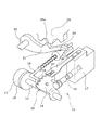
まず、図1及び図2に基づいてレンジ切換機構11の構成を説明する。
Hereinafter, an embodiment embodying the best mode for carrying out the present invention will be described.
First, the configuration of the
レンジ切換機構11は、自動変速機12のシフトレンジを、例えば、Pレンジ(パーキングレンジ)、Rレンジ(リバースレンジ)、Nレンジ(ニュートラルレンジ)、Dレンジ(ドライブレンジ)、2レンジ、Lレンジ(ローレンジ)に切り換えるためのものである。このレンジ切換機構11の駆動源となるモータ13は、例えばスイッチトリラクタンスモータ(SRモータ)等の同期モータにより構成され、減速機構14(図2参照)を内蔵し、この減速機構14の回転軸に嵌合連結された出力軸15の回転位置を検出する出力軸センサ16が設けられている。この出力軸センサ16は、P,R,N,D,2,Lの各レンジに対応する回転角度範囲でオン(ON)する6個の接点を有するスイッチにより構成され、いずれの接点がオン状態であるかを判別することによって実シフトレンジを検出するようになっている。
The
一方、出力軸15には、自動変速機12の油圧回路のマニュアルバルブ17を切り換えるためのディテントレバー18(レンジ切換部材)が固定されている。このディテントレバー18にはL字形のパーキングロッド19が固定され、このパーキングロッド19の先端部に設けられた円錐体20がロックレバー21に当接している。このロックレバー21は、円錐体20の位置に応じて軸22を中心にして上下動してパーキングギヤ23をロック/ロック解除するようになっている。このパーキングギヤ23は、自動変速機12の出力軸に設けられ、このパーキングギヤ23がロックレバー21によってロックされると、車両の駆動輪が回り止めされた状態(パーキング状態)に保持される。
On the other hand, a detent lever 18 (range switching member) for switching the
また、ディテントレバー18には、マニュアルバルブ17のスプール弁24が連結され、モータ13によって出力軸15と一体にディテントレバー18を回動させることで、マニュアルバルブ17のスプール弁24の位置を切り換えて自動変速機12に内蔵された油圧クラッチを、Pレンジ、Rレンジ、Nレンジ、Dレンジ、2レンジ、Lレンジのいずれかの状態に切り換える。この場合、Dレンジ、2レンジ、Lレンジが特許請求の範囲でいう走行レンジである。
Further, the
ディテントレバー18には、スプール弁24を上記各レンジに対応する位置に保持するための6個の保持凹部25(図3参照)が形成され、ディテントレバー18を各レンジに対応する位置に保持するためのディテントバネ26がマニュアルバルブ17に固定されている。このディテントバネ26の先端に設けられた係合部27がディテントレバー18の目標レンジの保持凹部25に嵌まり込むことで、ディテントレバー15が目標レンジの回転位置で保持されて、マニュアルバルブ17のスプール弁24の位置が目標レンジの位置で保持されるようになっている。図3に示すように、ディテントレバー18の6個の保持凹部25は、Pレンジ、Rレンジ、Nレンジ、Dレンジ、2レンジ、Lレンジの順序に配置され、ディテントレバー18(係合部27)の可動範囲の一方の限界位置にPレンジが隣接し、他方の限界位置にD以外の走行レンジであるLレンジが隣接した構成となっている。尚、ディテントレバー18とディテントバネ26等からディテント機構28が構成されている。
The
Pレンジでは、パーキングロッド19がロックレバー21に接近する方向に移動して、円錐体20の太い部分がロックレバー21を押し上げてロックレバー21の凸部21aがパーキングギヤ23に嵌まり込んでパーキングギヤ23をロックした状態となり、それによって、自動変速機12の出力軸(車両の駆動輪)がロックされた状態(パーキング状態)に保持される。
In the P range, the
Pレンジ以外のレンジでは、パーキングロッド19がロックレバー21から離れる方向に移動して、円錐体20の太い部分がロックレバー21から抜け出てロックレバー21が下降し、それによって、ロックレバー21の凸部21aがパーキングギヤ20から外れてパーキングギヤ20のロックが解除され、自動変速機12の出力軸が回転可能な状態(走行可能な状態)に保持される。
In ranges other than the P range, the
一方、モータ13には、ロータの回転位置を検出するためのエンコーダ31が設けられている。このエンコーダ31は、例えば磁気式のロータリエンコーダにより構成されており、モータ13のロータの回転に同期してA相、B相、Z相のパルス信号をレンジ切換制御装置32に出力するように構成されている。このレンジ切換制御装置32に設けられたレンジ切換制御用ECU33(マイクロコンピュータ)は、エンコーダ31から出力されるA相信号とB相信号の立ち上がり/立ち下がりの両方のエッジをカウントして、そのエンコーダカウント値に応じてモータ駆動回路34によってモータ13の通電相を所定の順序で切り換えることでモータ13を回転駆動する。
On the other hand, the
この際、A相信号とB相信号の発生順序によってロータの回転方向を判定し、正回転方向(Pレンジ→Dレンジの回転方向)ではエンコーダカウント値をカウントアップし、逆回転方向(Dレンジ→Pレンジの回転方向)ではエンコーダカウント値をカウントダウンする。これにより、モータ13が正回転/逆回転のいずれの方向に回転しても、エンコーダカウント値とモータ13の回転位置との対応関係が維持されるため、正回転/逆回転のいずれの回転方向でも、エンコーダカウント値によってモータ13の回転位置を検出して、その回転位置に対応した相の巻線に通電してモータ13を回転駆動することが可能となる。尚、エンコーダ31のZ相信号は、ロータの基準回転位置を検出するのに用いられる。
At this time, the rotation direction of the rotor is determined based on the generation order of the A-phase signal and the B-phase signal, the encoder count value is counted up in the forward rotation direction (P range → D range rotation direction), and the reverse rotation direction (D range) (→ P range rotation direction) The encoder count value is counted down. As a result, the correspondence relationship between the encoder count value and the rotational position of the
本実施例では、レンジ切換機構11の実シフトレンジを検出するシフトレンジ検出手段として出力軸センサ16を用いるようにしたが、この出力軸センサ16を省略して、エンコーダカウント値によって実シフトレンジを検出するようにしても良い。
In this embodiment, the
運転者が自動変速機12のシフトレバーを操作すると、そのシフトレバーの操作位置(目標レンジ)がシフトレンジ検出装置36によって検出され、このシフトレンジ検出装置28の出力信号(目標レンジの信号)がレンジ切換制御用ECU33に入力される。これにより、レンジ切換制御用ECU33は、目標レンジに対応する目標回転角(エンコーダカウント値の目標値)を設定して、モータ13への通電を開始し、エンコーダカウント値が目標値と一致する位置で停止するようにモータ13をフィードバック制御する。
When the driver operates the shift lever of the
ところで、モータ13の回転量(回転角度)は、減速機構14、出力軸15、ディテントレバー18等からなる回転伝達系を介してレンジ切換機構11の操作量(パーキングロッド19のスライド量)に変換されるが、回転伝達系を構成する部品間には、遊び(ガタ)が存在する。例えば、減速機構14の歯車間のバックラッシが存在し、また、モータ13の回転軸の先端部に形成した断面非円形の連結部を出力軸15の嵌合穴に嵌め込んで連結する構成では、両者の嵌め込み作業を容易にするためのクリアランスが必要となる。
By the way, the rotation amount (rotation angle) of the
また、図3に示すように、ディテントバネ26の係合部27がディテントレバー18のPレンジ側やLレンジ側の各保持凹部25に嵌まり込んだときに、係合部27と各保持凹部25の側壁との間に僅かな隙間(ガタ)が存在する。このように、モータ13の回転量をレンジ切換機構11の操作量(ディテントレバー18の回転角度)に変換する回転伝達系には、バックラッシや部品間の隙間等による遊び(ガタ)が存在するため、エンコーダカウント値に基づいてモータ13の回転量(回転角度)を正確に制御しても、レンジ切換機構11の操作量には回転伝達系の遊び(ガタ)分の誤差が生じてしまい、レンジ切換機構11の操作量を精度良く制御することができない。
Further, as shown in FIG. 3, when the engaging
そこで、本実施例では、回転伝達系の遊び量を学習する機能(学習手段)をレンジ切換制御用ECU33に持たせている。具体的には、システム起動時(電源オン時)に、目標レンジがPレンジになっているときに、ディテントバネ26の係合部27がレンジ切換機構11の可動範囲のPレンジ側の限界位置であるPレンジ保持凹部25の側壁(以下「Pレンジ壁」という)に突き当たるまでモータ13を逆回転させる“Pレンジ壁突き当て制御”を実施して、Pレンジ壁位置のエンコーダカウント値Np(Pレンジ壁位置学習値)を学習する。
Therefore, in this embodiment, the range
その後、運転者がシフトレバーを操作して目標レンジがPレンジからDレンジ、2レンジ、Lレンジのいずれかの走行レンジに切り換えられると、レンジ切換機構11の可動範囲のLレンジ側(走行レンジ側)の限界位置であるLレンジ保持凹部25の側壁(以下「Lレンジ壁」という)に突き当たるまでモータ13を正回転させる“Lレンジ壁突き当て制御”を実施して、Lレンジ壁位置のエンコーダカウント値Nl(Lレンジ壁位置学習値)を学習する。
Thereafter, when the driver operates the shift lever to switch the target range from the P range to the D range, the 2 range, or the L range, the L range side (travel range) of the movable range of the
この後、Pレンジ壁位置からLレンジ壁位置までのエンコーダカウント値の増減量(Nl−Np)をレンジ切換機構11の可動範囲の実測値として求めた後、この可動範囲の実測値と該可動範囲の設計値との差分を回転伝達系の遊び量として学習し、この回転伝達系の遊び量の学習値を電源オフ時でも記憶保持可能な記憶手段であるバックアップRAM37に記憶する。
回転伝達系の遊び量=可動範囲の実測値−設計値
After that, an increase / decrease amount (Nl−Np) of the encoder count value from the P range wall position to the L range wall position is obtained as an actual value of the movable range of the
Play amount of rotation transmission system = Actual value of movable range-Design value
この後は、モータ13を目標レンジに相当する目標位置(目標カウント値)まで回転させる際に、当該目標位置をPレンジ壁位置学習値Npを基準にして回転伝達系の遊び量の学習値とモータ13の回転方向を考慮して設定する。このようにすれば、回転伝達系に遊び(ガタ)があっても、その遊び(ガタ)を含めた目標位置を設定することができ、レンジ切換機構11の操作量を精度良く制御することができる。
Thereafter, when the
本実施例のように、複数の走行レンジを持つシステム(Dレンジの他に、Lレンジ等を持つシステム)では、レンジ切換機構11の可動範囲の走行レンジ側の限界位置に隣接するシフトレンジは、Dレンジではなく、Lレンジとなるため、目標レンジがLレンジになったときに、Lレンジ壁突き当て制御を実施して、Lレンジ壁位置を学習することが考えられる。しかし、大多数の運転者は、Dレンジのみで走行し、Lレンジで走行する機会がほとんどないため、Lレンジ壁位置を学習する機会がほとんどない。このため、Lレンジ壁位置の学習(回転伝達系の遊び量の学習)を行わずにレンジ切換制御を実施せざるを得ず、モータ駆動式のレンジ切換制御システムの信頼性を低下させてしまうという問題がある。
As in this embodiment, in a system having a plurality of travel ranges (a system having an L range and the like in addition to the D range), the shift range adjacent to the limit position on the travel range side of the movable range of the
この対策として、本実施例では、目標レンジがPレンジからDレンジ、2レンジ、Lレンジのいずれかの走行レンジに切り換えられときに、Lレンジ壁位置を学習した後、シフトレンジを本来の目標レンジに切り換えるようにしている。 As a countermeasure, in this embodiment, when the target range is switched from the P range to the D range, the 2 range, or the L range, after learning the L range wall position, the shift range is changed to the original target range. The range is switched.
この構成では、運転者がPレンジからDレンジに切り換えて車両を発進させるときに、Lレンジ壁突き当て制御を実施してLレンジ壁位置を学習することができるため、運転者がLレンジに切り換えない場合でも、発進時にLレンジ壁位置を確実に学習することができて、モータ駆動式のレンジ切換制御システムの信頼性を向上させることができる。 In this configuration, when the driver switches from the P range to the D range and starts the vehicle, the L range wall abutting control can be performed to learn the L range wall position. Even when switching is not performed, the L range wall position can be reliably learned at the time of start, and the reliability of the motor-driven range switching control system can be improved.
この場合、Lレンジ壁位置の学習に要する時間は短いため、通常は、運転者がPレンジからDレンジに切り換えてアクセルペダルを踏み込んで車両を発進させるまでの短い時間内で学習を終了してDレンジに戻すことができ、また、仮に、学習終了前にアクセルペダルが踏み込まれたとしても、LレンジもDレンジと同様に前進方向の駆動力を駆動輪に伝達する走行レンジであるため、Dレンジと同様に発進可能であり、発進性能を損なうことはない。 In this case, since the time required for learning the L range wall position is short, the learning usually ends within a short time from when the driver switches from the P range to the D range and depresses the accelerator pedal to start the vehicle. Even if the accelerator pedal is depressed before the end of learning, the L range is a traveling range that transmits the driving force in the forward direction to the driving wheels in the same way as the D range. The vehicle can be started in the same manner as the D range, and the starting performance is not impaired.
本発明は、例えば、運転者がDレンジに切り換える毎にLレンジ壁位置を学習するようにしても良いが、この学習時のLレンジ壁突き当て制御は、モータ13の駆動力によって回転伝達系の部品をLレンジ壁に突き当てた状態にするため、回転伝達系の部品に負担がかかる。そのため、Lレンジ壁突き当て制御の実行回数が多くなるに従って、回転伝達系の部品が徐々に変形・損傷する可能性があり、システムの耐久性・信頼性を低下させる原因となる。
In the present invention, for example, the L range wall position may be learned every time the driver switches to the D range. The L range wall abutting control at the time of learning is performed by the rotation transmission system by the driving force of the
この対策として、本実施例では、Pレンジ壁位置とLレンジ壁位置を一通り学習した後に、Pレンジ壁位置とLレンジ壁位置の学習値に基づいて回転伝達系の遊び量を学習し、この回転伝達系の遊び量の学習値を、電源オフ時でも記憶保持可能な記憶手段であるバックアップRAM37に記憶しておき、このバックアップRAM37に回転伝達系の遊び量の学習値が記憶されている場合には、Lレンジ壁位置の学習を行わないようにしている。
As a countermeasure, in this embodiment, after learning the P range wall position and the L range wall position as a whole, the play amount of the rotation transmission system is learned based on the learned values of the P range wall position and the L range wall position. The learning value of the amount of play of the rotation transmission system is stored in a
つまり、回転伝達系の遊び量は、回転伝達系の部品の摩耗・変形によって少しずつ変化するが、この変化は、長い期間を経過して徐々に現れる変化であるため、通常は、この経時的な変化をほとんど無視でき、回転伝達系の遊び量を一定値として取り扱っても問題はない。従って、Pレンジ壁位置とLレンジ壁位置をそれぞれ学習してそれらの学習値から回転伝達系の遊び量を学習してバックアップRAM37に保存しておけば、その後は、システム起動時(電源オン時)にPレンジ壁位置を学習するだけで、そのPレンジ壁位置の学習値を基準にして回転伝達系の遊び量の学習値を用いて目標レンジに相当するモータ13の目標回転位置を正確に設定することができるため、Lレンジ壁位置の学習を行う必要はない。これにより、Lレンジ壁突き当て制御の実行回数を大幅に少なくすることができ、システムの耐久性・信頼性を向上させることができる。
In other words, the amount of play in the rotation transmission system changes little by little due to wear and deformation of the components of the rotation transmission system, but this change is a change that gradually appears over a long period of time. Therefore, there is no problem even if the amount of play in the rotation transmission system is treated as a constant value. Therefore, if the P range wall position and the L range wall position are learned and the play amount of the rotation transmission system is learned from the learned values and stored in the
更に、本実施例では、所定期間毎、所定走行回数毎又は所定積算走行距離毎に、目標レンジがDレンジ、2レンジ、Lレンジのいずれかの走行レンジになったときにLレンジ壁位置の学習を行うようにしている。このようにすれば、回転伝達系の部品の摩耗・変形による回転伝達系の遊び量の経時的な変化を定期的に学習することができ、長期間にわたって制御精度の低下を防止することができる。 Further, in this embodiment, the L range wall position is detected when the target range is any of the D range, the 2 range, and the L range every predetermined period, every predetermined number of times of travel, or every predetermined total travel distance. I try to learn. In this way, it is possible to periodically learn the change over time in the amount of play in the rotation transmission system due to wear and deformation of the components of the rotation transmission system, and to prevent a reduction in control accuracy over a long period of time. .
以上説明した本実施例のLレンジ壁位置の学習は、レンジ切換制御用ECU33によって図4のLレンジ壁位置学習プログラムに従って次のようにして実行される。この図4のLレンジ壁位置学習プログラムは、システム起動時(電源オン時)に起動され、特許請求の範囲でいう学習手段としての役割を果たす。
The learning of the L range wall position according to the present embodiment described above is executed by the range
本プログラムが起動されると、まずステップ101で、Lレンジ壁位置を学習済みであるか否か(回転伝達系の遊び量の学習値がバックアップRAM37に記憶されているか否か)を判定し、まだLレンジ壁位置を学習していなければ、ステップ103に進み、目標レンジがDレンジ、2レンジ、Lレンジのいずれかの走行レンジに切り換えられたか否かを判定し、いずれかの走行レンジに切り換えられるまで待機する。
When this program is started, first, in
その後、目標レンジがDレンジ、2レンジ、Lレンジのいずれかの走行レンジに切り換えられた時点で、ステップ104に進み、Lレンジ壁突き当て制御を実施してLレンジ壁位置を学習し、次のステップ105で、Pレンジ壁位置の学習値とLレンジ壁位置の学習値とに基づいて回転伝達系の遊び量を学習して、その学習値をバックアップRAM37に記憶する。この後、ステップ106に進み、シフトレンジを本来の目標レンジに切り換える。
After that, when the target range is switched to one of the driving ranges of D range, 2 range, and L range, the process proceeds to step 104, the L range wall abutting control is performed, and the L range wall position is learned. In
また、上記ステップ101で、Lレンジ壁位置を学習済み(回転伝達系の遊び量の学習値がバックアップRAM37に記憶されている)と判定されれば、ステップ102に進み、前回のLレンジ壁位置の学習時から所定期間(又は所定走行回数又は所定積算走行距離)が経過したか否かを判定し、前回のLレンジ壁位置の学習時から所定期間(又は所定走行回数又は所定積算走行距離)が経過していなければ、そのまま本プログラムを終了する。一方、このステップ102で、前回のLレンジ壁位置の学習時から所定期間(又は所定走行回数又は所定積算走行距離)が経過したと判定されれば、上述したステップ103〜106の処理を実行し、目標レンジがDレンジ、2レンジ、Lレンジのいずれかの走行レンジに切り換えられた時点で、Lレンジ壁突き当て制御を実施してLレンジ壁位置を学習して回転伝達系の遊び量を学習し、その学習値をバックアップRAM37に更新記憶した後、シフトレンジを本来の目標レンジに切り換える。
If it is determined in
尚、本実施例では、Dレンジ以外の走行レンジとして、2レンジとLレンジの2つの走行レンジを設けたが、Lレンジのみであっても良く、勿論、Dレンジ以外の走行レンジが3つ以上であっても良い。 In the present embodiment, two travel ranges, the 2 range and the L range, are provided as travel ranges other than the D range. However, only the L range may be provided. Of course, there are three travel ranges other than the D range. It may be above.
また、本実施例では、シフトレバーによって目標レンジを指示するようにしたが、シフトレバー以外の操作部材で目標レンジを指示する構成としても良い。 In the present embodiment, the target range is instructed by the shift lever. However, the target range may be instructed by an operation member other than the shift lever.
その他、本発明は、レンジ切換機構11の構成を適宜変更しても良い等、種々変更して実施できることは言うまでもない。
In addition, it goes without saying that the present invention can be implemented with various changes such as the configuration of the
11…レンジ切換機構、12…自動変速機、13…モータ、14…減速機構、15…出力軸、16…出力軸センサ、17…マニュアルバルブ、18…ディテントレバー、19…パーキングロッド、21…ロックレバー、23…パーキングギヤ、24…スプール弁、25…保持凹部、26…ディテントバネ、27…係合部、28…ディテント機構、31…エンコーダ(回転位置検出手段)、32…レンジ切換制御装置、33…レンジ切換制御用ECU(学習手段)、36…シフトレンジ検出装置、37…バックアップRAM(電源オフ時でも記憶保持可能な記憶手段)
DESCRIPTION OF
Claims (3)
前記モータの回転位置を検出する回転位置検出手段と、
前記モータを前記レンジ切換部材の可動範囲の少なくとも一方の限界位置に突き当たるまで回転させる突き当て制御を実行してその限界位置を前記回転位置検出手段の検出値に基づいて学習する学習手段とを備えたレンジ切換制御装置において、
前記学習手段は、運転者のレンジ切換操作で設定された目標レンジがDレンジ又は前記D以外の走行レンジになったときに前記レンジ切換部材の可動範囲の前記走行レンジ側の限界位置に突き当たるまで前記モータを回転させる突き当て制御を実行して当該走行レンジ側の限界位置を学習した後、シフトレンジを本来の目標レンジに切り換えることを特徴とするレンジ切換制御装置。 The shift range is set to a range other than the P range, R range, N range, D range, and D by driving the motor according to the range switching operation of the driver and rotating the range switching member within a predetermined movable range. A range switching mechanism in which a P range is adjacent to one limit position of the movable range of the range switching member and a travel range other than the D is adjacent to the other limit position;
Rotational position detecting means for detecting the rotational position of the motor;
Learning means for executing abutting control for rotating the motor until it hits at least one limit position of the movable range of the range switching member and learning the limit position based on a detection value of the rotation position detecting means; In the range switching control device,
The learning means until the target range set by the driver's range switching operation reaches the limit position on the traveling range side of the movable range of the range switching member when the target range is a D range or a traveling range other than D. A range switching control device characterized by switching the shift range to an original target range after performing abutting control for rotating the motor and learning a limit position on the traveling range side.
前記学習手段は、前記記憶手段に前記回転伝達系の遊び量の学習値が記憶されている場合には前記走行レンジ側の限界位置の学習を行わないことを特徴とする請求項1に記載のレンジ切換制御装置。 The learning means executes abutting control to rotate the motor until it reaches the limit position on the P range side of the movable range of the range switching member when the target range is the P range, and sets the limit position on the P range side. Learning, calculating an actual measurement value of the movable range of the range switching member based on the learned value of the limit position on the P range side and the learned value of the limit position on the traveling range side, thereby calculating the play amount of the rotation transmission system Learning and storing the learned value in a storage means that can store and hold even when the power is turned off,
2. The learning device according to claim 1, wherein the learning unit does not learn the limit position on the traveling range side when a learning value of the play amount of the rotation transmission system is stored in the storage unit. Range switching control device.
Priority Applications (1)
| Application Number | Priority Date | Filing Date | Title |
|---|---|---|---|
| JP2007032945A JP2008196614A (en) | 2007-02-14 | 2007-02-14 | Range changeover control device |
Applications Claiming Priority (1)
| Application Number | Priority Date | Filing Date | Title |
|---|---|---|---|
| JP2007032945A JP2008196614A (en) | 2007-02-14 | 2007-02-14 | Range changeover control device |
Publications (1)
| Publication Number | Publication Date |
|---|---|
| JP2008196614A true JP2008196614A (en) | 2008-08-28 |
Family
ID=39755747
Family Applications (1)
| Application Number | Title | Priority Date | Filing Date |
|---|---|---|---|
| JP2007032945A Pending JP2008196614A (en) | 2007-02-14 | 2007-02-14 | Range changeover control device |
Country Status (1)
| Country | Link |
|---|---|
| JP (1) | JP2008196614A (en) |
Cited By (1)
| Publication number | Priority date | Publication date | Assignee | Title |
|---|---|---|---|---|
| JP2014173606A (en) * | 2013-03-06 | 2014-09-22 | Denso Corp | Range changeover device |
-
2007
- 2007-02-14 JP JP2007032945A patent/JP2008196614A/en active Pending
Cited By (1)
| Publication number | Priority date | Publication date | Assignee | Title |
|---|---|---|---|---|
| JP2014173606A (en) * | 2013-03-06 | 2014-09-22 | Denso Corp | Range changeover device |
Similar Documents
| Publication | Publication Date | Title |
|---|---|---|
| JP4302039B2 (en) | Motor control device | |
| JP4367620B2 (en) | Abnormality diagnosis device for motor drive system | |
| JP4385768B2 (en) | Motor control device | |
| JP4609418B2 (en) | Control device and control method for shift switching mechanism | |
| JP4968178B2 (en) | Control device for range switching mechanism | |
| JP5817747B2 (en) | Range switching device | |
| JP2009177965A (en) | Motor control device | |
| US10941861B2 (en) | Shift range control apparatus | |
| US7567051B2 (en) | Position shift control apparatus ensuring durability and operation accuracy thereof | |
| JP4410784B2 (en) | Control device and control method for shift switching mechanism | |
| US9580051B2 (en) | Control device and control method for vehicle | |
| US9403445B2 (en) | Motor controller | |
| JP2009095101A (en) | Motor controller | |
| US7713168B2 (en) | Control apparatus for shift range changeover device | |
| CN110382928B (en) | Shift gear control device | |
| JP6789461B2 (en) | Shift range controller | |
| US7245225B2 (en) | Failure monitor for motor drive control system | |
| JP4591396B2 (en) | Control device for range switching device | |
| JP2015010640A (en) | Range switching device | |
| JP2012110083A (en) | Motor controller | |
| US20080129236A1 (en) | Motor control device | |
| JP2005198450A (en) | Motor controller | |
| JP2013143822A (en) | Motor control device | |
| JP2014020459A (en) | Range switching device | |
| JP4572858B2 (en) | Shift-by-wire range switching device |