JP2008191069A - Reflector control type fast reactor, and neutron detector installation method and operation method for same - Google Patents
Reflector control type fast reactor, and neutron detector installation method and operation method for same Download PDFInfo
- Publication number
- JP2008191069A JP2008191069A JP2007027681A JP2007027681A JP2008191069A JP 2008191069 A JP2008191069 A JP 2008191069A JP 2007027681 A JP2007027681 A JP 2007027681A JP 2007027681 A JP2007027681 A JP 2007027681A JP 2008191069 A JP2008191069 A JP 2008191069A
- Authority
- JP
- Japan
- Prior art keywords
- neutron
- reflector
- core
- reactor
- fast reactor
- Prior art date
- Legal status (The legal status is an assumption and is not a legal conclusion. Google has not performed a legal analysis and makes no representation as to the accuracy of the status listed.)
- Pending
Links
Images


Classifications
-
- Y—GENERAL TAGGING OF NEW TECHNOLOGICAL DEVELOPMENTS; GENERAL TAGGING OF CROSS-SECTIONAL TECHNOLOGIES SPANNING OVER SEVERAL SECTIONS OF THE IPC; TECHNICAL SUBJECTS COVERED BY FORMER USPC CROSS-REFERENCE ART COLLECTIONS [XRACs] AND DIGESTS
- Y02—TECHNOLOGIES OR APPLICATIONS FOR MITIGATION OR ADAPTATION AGAINST CLIMATE CHANGE
- Y02E—REDUCTION OF GREENHOUSE GAS [GHG] EMISSIONS, RELATED TO ENERGY GENERATION, TRANSMISSION OR DISTRIBUTION
- Y02E30/00—Energy generation of nuclear origin
- Y02E30/30—Nuclear fission reactors
Landscapes
- Monitoring And Testing Of Nuclear Reactors (AREA)
Abstract
Description
本発明は、中性子反射体の移動により炉心の反応度を制御する反射体制御方式高速炉の中性子検出器設置方法及び運転方法、並びに反射体制御方式高速炉に関する。 The present invention relates to a neutron detector installation method and operation method for a reflector control type fast reactor that controls the reactivity of a core by moving a neutron reflector, and a reflector control type fast reactor.
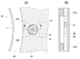
例えば、特許文献1及び2に記載の反射体制御方式高速炉の従来の一般的な構成を、図10〜図12を用いて説明する。図10は、従来の反射体制御方式高速炉を中心部から右半分のみ概略的に示し、図11は図10における高速炉の直径方向の断面を示し、図12は図11における燃料集合体を示している。
For example, the conventional general configuration of the reflector control type fast reactor described in
図10に示すように、原子炉容器1の内部には炉心2が中央部に位置し、この炉心2の周囲を囲繞する位置に中性子遮蔽体3が配置されると共に、ナトリウム等の液体金属の冷却材4が満たされている。
As shown in FIG. 10, a
前記炉心2は、図11に示すように、例えば六角形状の18本の燃料集合体5によって構成され、この中央部に、炉心2の反応度制御用で運転時には上方に引き抜かれる中性子吸収棒用のチャンネル6が配置されていると共に、炉心バレル7によって包囲されている。
As shown in FIG. 11, the
この炉心バレル7の外側には、所定間隔離間して冷却材4の流路を分割する隔壁8が配置され、この炉心バレル7と隔壁8との間に設けられた空間によって、炉心2の運転に使用する中性子反射体9の移動領域10が形成されている。
A
ここに、冷却材4は、隔壁8の内側を下から上方向に向かって流れ、その途中で炉心2に入り、核分裂によって生じた熱を奪って温度が上昇する。この温度が上昇した冷却材4は、図示しない中間熱交換器の内部に流入し、ここで二次系冷却材と熱交換を行った後、上記中間熱交換器から下方向へ流出する。この熱交換後の冷却された冷却材4は、隔壁8の外側を通って炉心2の下部に回り込み、再び炉心2に導入される。
Here, the coolant 4 flows from the lower side to the upper side of the
中性子遮蔽体3は、原子炉容器1の中性子照射量を反射体制御方式高速炉の全寿命にわたって所定値以下に制限するものであり、前記原子炉容器1と隔壁8との間に配置された複数の中性子遮蔽棒11によって構成されている。
The neutron shield 3 limits the amount of neutron irradiation of the
この中性子遮蔽体3の構成としては、ステンレス鋼等からなる構造体の他に、中性子吸収能力の大きいボロンを含むB4Cセラミックを収納したピンを配置したり、またハフニウム、タンタル等の金属またはそれらの化合物を含むようにすることができる。 As a configuration of the neutron shield 3, in addition to a structure made of stainless steel or the like, a pin containing B 4 C ceramic containing boron having a large neutron absorption capability is arranged, or a metal such as hafnium or tantalum or These compounds can be included.
また、冷却材よりも中性子反射能力が劣る中性子吸収体あるいは中性子透過物質を中性子反射体9の上部領域24に配置することにより、中性子反射体9による炉心2の反応度制御能力を増大させることができる(例えば、特許文献3参照)。尚、符号12は、原子炉容器1の周囲を包囲するガードベッセルである。
Further, the ability of the
更に、ガードベッセル12の外側に中性子検出器25が設置される。この中性子検出器25の信号、熱出力測定装置等のデータを処理して、反射体制御方式高速炉は出力(核出力)が制御されて運転される。
Furthermore, a
燃料集合体5は、例えば図12に示すように、ステンレス鋼製の六角形状のラッパ管13の内部に多数の燃料ピン14を規則的に配列すると共に、ラッパ管13の上部および下部に中性子遮蔽体15a、15bを配置することにより構成されている。
In the
尚、同図は、多数の燃料ピン14のうちの1本を取り出して図示しており、この燃料ピン14には、燃料部14aと、核分裂により生じるガス成分を封じ込めるプレナム部14bとが備えられている。また、燃料ピン14は、ワイヤラップまたはグリッド(図示せず)により冷却材4の混合を促進すると共に、下部端栓部でラッパ管13に結合して固定されている。また、燃料集合体5は、小径のエントランスノズル16を介して炉心支持体17に差し込まれて固定されると共に、冷却材入口18と冷却材出口19とが備えられている。
In the figure, one of a large number of
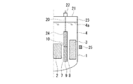
図11に示す炉心バレル7と隔壁8との間の移動領域10には、図10に示すように中性子反射体9が配置されている。この中性子反射体9は、駆動棒20の下端に吊り下げ支持され、この駆動棒20は、原子炉容器1の上端開口部を閉塞する遮蔽プラグ21を貫いて上方に延び、遮蔽プラグ21の上面に設置された駆動装置22によって上下方向、つまり炉心2の軸方向に移動するよう構成されている。
In the
すなわち、駆動装置22の駆動に伴って、駆動棒20を介して中性子反射体9が、炉心バレル7と隔壁8との間の移動領域10内を、炉心2に沿って上下方向(炉心2の軸方向)に移動するように構成されている。尚、冷却材4の液面4aと遮蔽プラグ21との間は、カバーガスで満たされたカバーガス空間23である。
That is, as the
これにより、中性子反射体9を、駆動装置22を介して炉心2の軸方向に移動させて炉心2からの中性子の漏洩を調整し、これにより炉心2の反応度が制御される。この反応度の制御は、炉心の起動停止や、燃料の燃焼による炉心反応度の低下を補償するために行われる。
As a result, the
反射体制御方式高速炉における炉心2の仕様の一例としては、表1に示すように、熱出力約120MWt、炉心径約130cm、炉心高さ200cmで、濃縮ウランの金属合金U−Zrを燃料とする炉心を燃料交換なしで約30年運転し、かつ、燃料の燃焼による反応度変化を補償するため、長さ200cmの中性子反射体を一定速度で引き上げて運転するものがある。
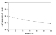
このときの炉心2の側部に設置された中性子検出器25が検出する中性子計数率の相対値を図14に示す。この結果では、炉心2の側部に設置された中性子検出器25による中性子計数率は、原子炉の運転が進むに従って減少しており、30年後の燃焼末期では燃焼初期に比べて約1桁小さくなる傾向にある。
FIG. 14 shows the relative value of the neutron count rate detected by the
図10に示す反射体制御方式高速炉において、原子炉運転中の中性子反射体9の軸方向移動は、図13に示すように、燃焼初期では中性子反射体9を引き上げて炉心2を臨界とし、その後、中性子反射体9を引き下げて一定出力で運転し、炉心2の燃焼による反応度低下を中性子反射体9の上昇で補い、30年後には中性子反射体9が炉心2の全体を覆うことになる。中性子検出器25が検出する中性子計数率の図14に示す変化傾向は、この中性子反射体9の軸方向移動に伴い中性子の流れが中性子検出器25に対して遮断されることに起因している。
In the reflector controlled fast reactor shown in FIG. 10, the axial movement of the
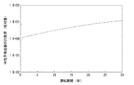
一方、図15に示すように中性子検出器25が炉心2の底部に設置された場合に、この中性子検出器25にて検出される中性子計数率を図16に示す。この場合の中性子計数率は、炉心2の側部に設置した中性子検出器25による中性子計数率とは逆に、原子炉の運転が進むに従って増大しており、30年後の燃焼末期では燃焼初期に比べて約1桁大きくなる傾向にある。この傾向は、この中性子反射体9の移動に伴い中性子が中性子検出器25に流れ込むことに起因している。
On the other hand, FIG. 16 shows the neutron count rate detected by the
以上のように、炉心2の側部或いは底部に設置された中性子検出器25が検出する中性子計数率は、原子炉の運転に伴う中性子反射体9の軸方向移動の影響を受けてそれぞれ約1桁の変動がある。従って、これらの中性子検出器25が検出する中性子計数率を用いて原子炉の出力(核出力)を制御する場合、中性子計数率の検出誤差が大きくなるので、安全側で運転するために、熱出力測定装置にて測定された熱出力の誤差を大きく見積もって、過大な出力にならないように制御する必要がある。その結果、定格出力よりも低い出力(核出力)での運転となり、経済性の低い反射体制御方式高速炉となってしまう。
従来の高速炉では、制御棒の操作などによって中性子束の歪まない炉外位置に中性子検出器を配置し、中性子束を監視することで出力を監視している。しかしながら、上述のような反射体制御方式高速炉においては、炉心2の側部或いは底部に設置された中性子検出器25が検出する中性子計数率は、高速炉の運転に伴う中性子反射体9の移動の影響を受けて、出力が変化していないにもかかわらず運転中約1桁の変動がある。すなわち、炉心2の出力と中性子検出器25が検出する中性子束との比例関係が変化してしまう。従来の高速炉においては、中性子検出器により検出される中性子計数率は20%程度の変動があり、これを熱出力誤差としても許容される。しかし、前述した反射体制御方式高速炉においては、中性子検出器25にて検出される中性子計数率が約1桁変動したときに、これを熱出力誤差として許容することは高速炉の経済性を損ねることになる。
In a conventional fast reactor, a neutron detector is placed at a position outside the reactor where the neutron flux is not distorted by operating a control rod, and the output is monitored by monitoring the neutron flux. However, in the reflector control type fast reactor as described above, the neutron count rate detected by the
本発明の目的は、上述の事情を考慮してなされたものであり、中性子反射体の移動に伴う中性子検出器の信号の変動の影響を小さくして検出誤差を低減し、熱出力誤差を小さく見積もって原子炉出力を制御し、これにより経済性の高い反射体制御方式高速炉を実現できる反射体制御方式高速炉の中性子検出器設置方法及び運転方法、並びに反射体制御方式高速炉を提供することにある。 The object of the present invention has been made in consideration of the above-mentioned circumstances. The influence of fluctuations in the signal of the neutron detector accompanying the movement of the neutron reflector is reduced to reduce the detection error, and the heat output error is reduced. Provided is a reflector control system fast reactor neutron detector installation method and operation method, and a reflector control system fast reactor that can control the reactor power by estimation and thereby realize a highly economical reflector control system fast reactor. There is.
本発明に係る反射体制御方式高速炉の中性子検出器設置方法は、原子炉容器内に収容された炉心の外側に設置される中性子反射体を前記炉心の軸方向に移動させて、前記炉心からの中性子の漏洩を調整することにより前記炉心の反応度を制御する反射体制御方式高速炉であって、前記原子炉容器外に中性子検出器を設置する反射体制御方式高速炉の中性子検出器設置方法において、前記中性子検出器を前記炉心の軸方向に複数設置し、このうちの少なくとも一つの中性子検出器を前記中性子反射体の移動範囲内に設置し、かつ、少なくとも一つの前記中性子検出器を前記中性子反射体の移動範囲外に設置し、これら移動範囲内および移動範囲外にそれぞれ設置された前記中性子検出器の信号を合算処理することを特徴とするものである。 In the reflector control method fast reactor neutron detector installation method according to the present invention, the neutron reflector installed outside the core housed in the reactor vessel is moved in the axial direction of the core, A reflector-controlled fast reactor that controls the reactivity of the core by adjusting leakage of neutrons, and a neutron detector installed in a reflector-controlled fast reactor in which a neutron detector is installed outside the reactor vessel In the method, a plurality of the neutron detectors are installed in the axial direction of the core, at least one of these neutron detectors is installed within a moving range of the neutron reflector, and at least one of the neutron detectors is installed. It is installed outside the moving range of the neutron reflector, and the signals of the neutron detectors installed inside and outside the moving range are summed up.
また、本発明に係る反射体制御方式高速炉の運転方法は、本発明に係る反射体制御方式高速炉の中性子検出器設置方法を用いて設置された中性子検出器からの検出信号を、当該検出信号以外で原子炉状態を監視する機能を持つ信号と組み合わせ、中性子反射体の移動に伴うそれぞれの信号の誤差を補完するように信号処理して、原子炉出力を制御することを特徴とするものである。 Also, the operating method of the reflector control type fast reactor according to the present invention is the detection signal from the neutron detector installed using the neutron detector installation method of the reflector control type fast reactor according to the present invention. Combined with a signal that has a function to monitor the reactor state other than the signal, the signal processing is performed to complement the error of each signal accompanying the movement of the neutron reflector, and the reactor output is controlled. It is.
更に、本発明に係る反射体制御方式高速炉は、原子炉容器内に収容された炉心の外側に設置される中性子反射体を前記炉心の軸方向に移動させて、前記炉心からの中性子の漏洩を調整することにより前記炉心の反応度を制御する反射体制御方式高速炉において、前記原子炉容器外には、前記炉心の軸方向に複数の中性子検出器が設置され、このうちの少なくとも一つの中性子検出器が前記中性子反射体の移動範囲内に設置され、かつ、少なくとも一つの前記中性子検出器が前記中性子反射体の移動範囲外に設置され、これら移動範囲の内、外にそれぞれ設置された前記中性子検出器の信号が合算処理されるよう構成されたことを特徴とするものである。 Furthermore, the reflector control type fast reactor according to the present invention moves a neutron reflector installed outside the core accommodated in the reactor vessel in the axial direction of the core, and leaks neutrons from the core. In the reflector control type fast reactor that controls the reactivity of the core by adjusting the plurality of neutron detectors in the axial direction of the core outside the reactor vessel, at least one of these A neutron detector is installed within the moving range of the neutron reflector, and at least one of the neutron detectors is installed outside the moving range of the neutron reflector, and is installed inside and outside these moving ranges, respectively. The neutron detector signals are combined and processed.
本発明に係る反射体制御方式高速炉の中性子検出器設置方法、及び反射体制御方式高速炉によれば、原子炉容器外で炉心の軸方向に複数設置される中性子検出器のうち、少なくとも一つの中性子検出器を中性子反射体の移動範囲内に設置し、かつ、少なくとも一つの中性子検出器を中性子反射体の移動範囲外に設置し、これら移動範囲の内、外にそれぞれ設置された中性子検出器の信号を合算処理する。このため、原子炉運転に伴う燃焼反応度分を補償するために中性子反射体が移動し、この中性子反射体の移動により、この移動範囲の内外にそれぞれ設置された中性子検出器の信号が変動しても、これらの信号を合算処理することで、各信号の変動の影響を小さくして検出誤差を低減できる。これにより、熱出力測定装置が測定した熱出力の誤差を小さく見積もることが可能となり、原子炉を定格出力で制御できるので、経済性の高い反射体制御方式高速炉を実現できる。 According to the reflector control type fast reactor installation method and reflector control type fast reactor according to the present invention, at least one of the neutron detectors installed in the axial direction of the core outside the reactor vessel. Two neutron detectors are installed within the moving range of the neutron reflector, and at least one neutron detector is installed outside the moving range of the neutron reflector, and the neutron detectors installed inside and outside these moving ranges, respectively. The signal of the instrument is summed up. For this reason, the neutron reflector moves to compensate for the combustion reactivity associated with the operation of the reactor, and the movement of this neutron reflector fluctuates the signals of the neutron detectors installed inside and outside this moving range. However, by adding these signals together, it is possible to reduce the influence of fluctuation of each signal and reduce the detection error. As a result, it is possible to estimate the error of the thermal output measured by the thermal output measuring device small, and the reactor can be controlled with the rated output, so that a highly economical reflector control type fast reactor can be realized.
また、本発明に係る反射体制御方式高速炉の運転方法によれば、中性子検出器からの検出信号を、当該検出信号以外で原子炉状態を監視する機能を持つ信号と組み合わせ、中性子反射体の移動に伴うそれぞれの信号の誤差を補完するように信号処理して原子炉出力を制御することから、各信号の誤差が低減されるので、信頼性の高い原子炉出力制御を実施でき、経済性の高い反射体制御方式高速炉を実現できる。 Further, according to the operation method of the reflector control type fast reactor according to the present invention, the detection signal from the neutron detector is combined with a signal having a function of monitoring the reactor state other than the detection signal, and the neutron reflector Since the signal output is controlled to compensate for the error of each signal that accompanies the movement and the output of the reactor is controlled, the error of each signal is reduced. A high-speed reflector control system fast reactor can be realized.
以下、本発明を実施するための最良の形態を、図面に基づき説明する。但し、本発明は、これらの実施の形態に限定されるものではない。 The best mode for carrying out the present invention will be described below with reference to the drawings. However, the present invention is not limited to these embodiments.
[A]第1の実施の形態(図1〜図4)
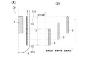
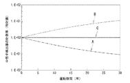
図1は、(A)が、本発明に係る反射体制御方式高速炉の中性子検出器設置方法における第1の実施の形態を実施した反射体制御方式高速炉を軸方向に切断して示す概略半断面図であり、(B)が、図1(A)の中性子反射体の移動位置を示す図である。図2は、図1(A)の中性子検出器により検出された中性子計数率などを示すグラフである。この第1の実施の形態において、前記背景技術と同様な部分は、同一の符号を付して説明を簡略化し、または省略する。
[A] First embodiment (FIGS. 1 to 4)
FIG. 1A is a schematic view of a reflector control type fast reactor in which the first embodiment of the neutron detector installation method for a reflector control type fast reactor according to the present invention is cut in the axial direction. It is a half section and (B) is a figure showing the movement position of the neutron reflector of Drawing 1 (A). FIG. 2 is a graph showing the neutron count rate detected by the neutron detector of FIG. In the first embodiment, the same parts as those in the background art are denoted by the same reference numerals, and the description is simplified or omitted.
図1(A)に示す反射体制御方式高速炉30では、原子炉容器1内に収容されて液体金属の冷却材に浸される炉心2の外側で、且つ原子炉容器1の内側に中性子反射体9が設置されている。この中性子反射体9を炉心2の軸方向に移動させて、炉心2からの中性子の漏洩を調整することにより、炉心2の反応度が制御される。
In the reflector control type
このような反射体制御方式高速炉30では、炉心2からの中性子の漏洩を検出する中性子検出器が、炉心2の軸方向に複数設置される。このうち、原子炉容器1の側部に少なくとも一つの中性子検出器(本実施の形態では1個の中性子検出器31A)が設置され、原子炉容器1の下部に少なくとも一つの中性子検出器(本実施の形態では1個の中性子検出器31B)が設置される。
In such a reflector control type
ところで、中性子反射体9は、図1(B)に示すように、運転初期(燃焼初期)において炉心2の下部に位置して炉心2の下部の燃料を燃焼させ、その後炉心2の反応度の低下を補うために徐々に上昇して、炉心2の順次上方の燃料を燃焼させている。中性子反射体9は、このように反射体制御方式高速炉30の全運転期間に亘って炉心2の軸方向に移動する。この中性子反射体9の移動範囲X内に中性子検出器31Aが設置され、移動範囲外に中性子検出器31Bが設置される。
By the way, as shown in FIG. 1B, the
これらの中性子検出器31A及び31Bには、炉心2から直接透過してくる中性子と、炉心2から上下方向或いは斜め方向に透過し、原子炉容器1の内外の、物質密度の比較的小さな領域や空隙部分を経て間接的に至る中性子とが検出される。これらの中性子は、反射体制御方式高速炉30の運転期間中において中性子反射体9の移動に伴い中性子検出器31A、31Bに対する寄与が変動するため、中性子検出器31A及び31Bでは、検出する中性子計数率が例えば年間3%程度変動する。
In these
中性子検出器31Aでは、図2の一点鎖線A及び図14に示すように、運転初期には炉心2から透過して直接中性子検出器31Aに至る中性子が比較的多いため、中性子検出器31Aにて検出される中性子計数率は、運転初期には高いが、中性子反射体9の上昇に伴って徐々に減少する。また、中性子検出器31Bでは、図2の破線Bに示すように、中性子反射体9が最も上昇した位置となる運転末期(燃焼末期)において、炉心2から透過して直接中性子検出器31Bに至る中性子が比較的多くなるので、中性子検出器31Bにて検出される中性子計数率は、運転初期には少ないが、中性子反射体9の上昇に伴って徐々に増加する。
In the
そこで、中性子検出器31Aと31Bからの検出信号を合算処理して合算処理信号を得ることとする。これにより、この合算処理信号は、図2の実線Cに示すように、中性子検出器31A、31Bからのそれぞれの検出信号が中性子反射体9の移動に伴って図2の一点鎖線A、破線Bのように変動しても、この変動の影響を小さくでき、中性子検出器31A及び31Bによる中性子計数率の検出誤差を低減できる。
Therefore, the detection signals from the
従って、本実施の形態によれば、次の効果を奏する。 Therefore, according to the present embodiment, the following effects can be obtained.
原子炉容器1内で炉心2の軸方向に設置される中性子検出器31A、31Bのうち、中性子検出器31Aを中性子反射体9の移動範囲X内に設置し、且つ中性子検出器31Bを中性子反射体9の移動範囲X外に設置し、これらの移動範囲Xの内、外にそれぞれ設置された中性子検出器31A、31Bの中性子計数率に関する検出信号を合算処理する。このため、原子炉運転に伴う燃焼反応度分を補償するために中性子反射体9が移動し、この中性子反射体9の移動により、この移動範囲Xの内外にそれぞれ設置された中性子検出器31A、31Bの検出信号が変動しても、これらの検出信号を合算処理することで、各検出信号の変動の影響を小さくでき、中性子検出器31A、31Bにて検出された中性子計数率に関する検出誤差を低減できる。これにより、熱出力測定装置(不図示)が測定した熱出力の誤差を小さく見積もることが可能となり、炉心2を定格出力で制御できるので、経済性の高い反射体制御方式高速炉30を実現できる。
Of the
尚、上記熱出力測定装置は、冷却材における炉心2の出口と入口の温度差から熱出力を測定するものである。また、中性子反射体9の移動範囲X外に設置される中性子検出器31Bは、炉心2の下部に設置されるものに限らず、図3に示すように、炉心2の上部に設置されてもよく、或いは図4に示すように、炉心2の底部に設置されてもよい。これらの場合にも、中性子反射体9の移動範囲X内に設置された中性子検出器31Aによる検出信号と合算処理することで、上記(1)と同様な効果を奏する。
The thermal output measuring device measures the thermal output from the temperature difference between the outlet and the inlet of the
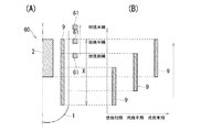
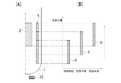
[B]第2の実施の形態(図5、図6)
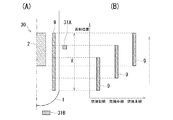
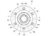
図5は、(A)が、本発明に係る反射体制御方式高速炉の中性子検出器設置方法における第2の実施の形態を実施した反射体制御方式高速炉を軸方向に切断して示す概略断面図であり、(B)が、図5(A)の中性子反射体の移動位置を示す図である。図6は、図5(A)の反射体制御方式高速炉を直径方向に切断して示す断面図である。この第2の実施の形態において、前記第1の実施の形態及び背景技術と同様な部分は、同一の符号を付して説明を簡略化し、または省略する。
[B] Second embodiment (FIGS. 5 and 6)
5A is a schematic diagram showing a reflector control type fast reactor in which the second embodiment of the neutron detector installation method of the reflector control type fast reactor according to the present invention is cut in the axial direction. It is sectional drawing, (B) is a figure which shows the movement position of the neutron reflector of FIG. 5 (A). FIG. 6 is a cross-sectional view showing the reflector control type fast reactor of FIG. In the second embodiment, the same parts as those in the first embodiment and the background art are denoted by the same reference numerals, and the description will be simplified or omitted.
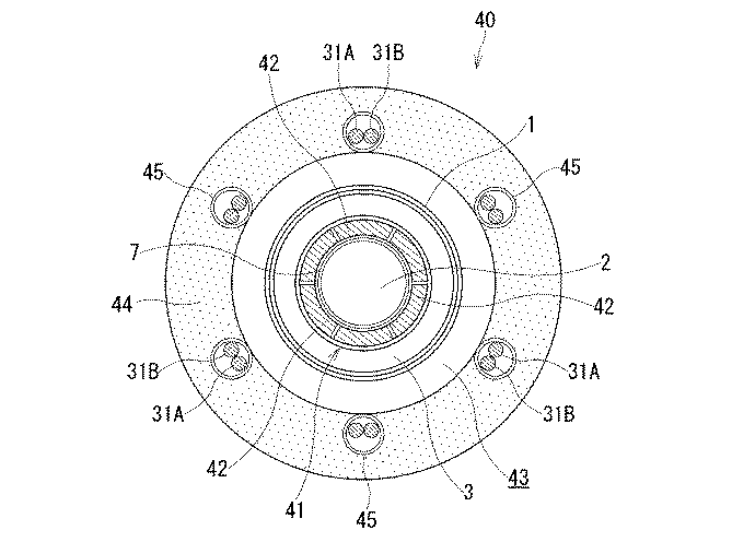
本実施の形態の反射体制御方式高速炉40では、中性子反射体41が周方向に分割されて複数、例えば6個のセクター42から構成され、各セクター42が独立して、駆動装置22により制御棒20(共に図10参照)を介して炉心2の軸方向に移動するよう構成されている。
In the reflector control type
このような反射体制御方式高速炉40では、各セクター42に正対する位置に中性子検出器が、炉心2の軸方向に沿って複数設置される。つまり、各セクター42毎に、当該セクター42の移動範囲Yの内側および外側に少なくとも一つの中性子検出器(本実施の形態では、移動範囲Y内に1個の中性子検出器31Aが、移動範囲Y外に1個の中性子検出器31B)がそれぞれ設置されている。尚、セクター42の移動範囲Yは、前記実施の形態における中性子反射体9の移動範囲Xと同一である。
In such a reflector control type
中性子検出器31A及び31Bは、図6に示すように、原子炉容器1の外側に空間43を設けて設置されるコンクリート躯体44の案内管45の内部に収容される。この案内管45は、コンクリート躯体44内に、炉心2の軸方向に延在して埋設されたものである。各セクター42毎に設置された中性子検出器31A及び31Bにて検出されたそれぞれの中性子計数率の検出信号は、前記実施の形態と同様に合算処理されて、各セクター42毎に中性子計数率の合算処理信号が得られる。
As shown in FIG. 6, the neutron detectors 31 </ b> A and 31 </ b> B are accommodated in a
従って、本実施の形態によれば、次の効果を奏する。 Therefore, according to the present embodiment, the following effects can be obtained.
中性子反射体41を分割した各セクター42が独立して移動する場合にも、各セクター42毎に、当該セクター42の移動方向Yの内側および外側に中性子検出器31A、31Bが設置され、これらの中性子検出器31A、31Bにて検出された中性子計数率の検出信号が合算処理されて合算処理信号が得られる。このことから、上記合算処理信号は、中性子検出器31A、31Bの検出信号がセクター42の移動に伴って変動しても、この変動の影響を小さくしたものとなり、中性子計数率に関する検出誤差を低減できる。従って、炉心2の全体として中性子計数率を高精度に検出でき、前記第1の実施の形態と同様に、炉心2を定格出力で運転して、経済性の高い反射体制御方式高速炉40を実現できる。
Also when each
[C]第3の実施の形態(図7)
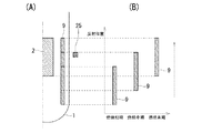
図7は、(A)が、本発明に係る反射体制御方式高速炉の中性子検出器設置方法における第3の実施の形態を実施した反射体制御方式高速炉を直径方向に切断して示す部分断面図であり、(B)が、図7(A)のVII‐VII線に沿う断面図である。この第3の実施の形態において、前記第1、第2の実施の形態及び背景技術と同様な部分は、同一の符号を付して説明を簡略化し、または省略する。
[C] Third embodiment (FIG. 7)
FIG. 7 (A) shows a part of the reflector control type fast reactor implemented in the third embodiment in the method for installing the neutron detector of the reflector control type fast reactor according to the present invention cut in the diameter direction. It is sectional drawing, (B) is sectional drawing which follows the VII-VII line of FIG. 7 (A). In the third embodiment, the same parts as those in the first and second embodiments and the background art are denoted by the same reference numerals, and the description will be simplified or omitted.
本実施の形態の反射体制御方式高速炉50では、第1または第2の実施の形態の中性子検出器31A、31Bの他に、炉心2の軸方向の中性子束分布を測定可能な中性子束分布測定器51が設置されている。この中性子束分布測定器51は、第1または第2の実施の形態の中性子検出器31A、31Bの近傍に設置されて、炉心2の軸方向に移動可能に設けられる。例えば、中性子束分布測定器51は、案内管52内に収容され、この案内管52の軸方向に沿って移動可能に設けられる。この案内管52は、案内管45内において、この案内管45の軸方向に沿って収納されている。
In the reflector control type
この中性子束分布測定器51を、中性子検出器31Aと31Bとの間で、炉心2の軸方向に沿って移動させることで、その時点における中性子束の、炉心2の軸方向に沿う分布を測定できる。この中性子束分布の時系列変化を分析することで、中性子検出器31A、31Bが検出する中性子計数率の検出信号が中性子反射体9または中性子反射体41のセクター42の移動により変動したときにも、その変動量を把握することが可能となる。そして、この変動量を補正すべく中性子検出器31A、31Bの位置が調整される。
The neutron flux
例えば、中性子検出器31Bでは、図2の破線Bに示すように、中性子反射体9の移動によって、検出される中性子計数率が増加するが、この増加を補正するように、中性子検出器31Aの位置を上方に調整する。このように位置調整された中性子検出器31Aと31Bからの中性子計数率に関する検出信号を合算処理して合算処理信号を得る。
For example, in the
従って、本実施の形態によれば、前記第1または第2の実施の形態と同様な効果を奏するほか、次の効果を奏する。 Therefore, according to this embodiment, in addition to the same effects as those of the first or second embodiment, the following effects can be obtained.
中性子検出器31A、31Bの近傍に設置された中性子束分布測定器51によって、炉心2の軸方向の中性子束分布を測定し、この中性子束分布を用いて、中性子検出器31A、31Bの検出信号が中性子反射体9または中性子反射体41のセクター42の移動により変動したときの変動量を補正するように、中性子検出器31A、31Bの位置を調整する。これによって、中性子検出器31A、31Bからの検出信号の変動を低減できるので、これらの中性子検出器31Aと31Bにて検出された中性子計数率に関する検出誤差をより一層低減でき、この結果、経済性がより高い反射体制御方式高速炉50を実現できる。
The neutron flux
[D]第4の実施の形態(図8)
図8は、(A)が、本発明に係る反射体制御方式高速炉の中性子検出器設置方法における第4の実施の形態を実施した反射体制御方式高速炉を軸方向に切断して示す概略半断面図であり、(B)が、図8(A)の中性子反射体の移動位置を示す図である。この第4の実施の形態において、前記第1の実施の形態及び背景技術と同様な部分は、同一の符号を付して説明を簡略化し、または省略する。
[D] Fourth embodiment (FIG. 8)
FIG. 8: is the outline which shows (A) by cut | disconnecting the reflector control type fast reactor which implemented 4th Embodiment in the neutron detector installation method of the reflector control type fast reactor which concerns on this invention to an axial direction. FIG. 9B is a half cross-sectional view, and FIG. 9B is a diagram illustrating a moving position of the neutron reflector of FIG. In the fourth embodiment, the same parts as those in the first embodiment and the background art are denoted by the same reference numerals, and the description will be simplified or omitted.
本実施の形態における反射体制御方式高速炉60では、原子炉容器1内に設置される1または複数の中性子検出器(本実施の形態では1個の中性子検出器61)を中性子反射体9の移動に追随して炉心2の軸方向に移動させ、これにより中性子検出器61を中性子反射体9の移動範囲X外に常に位置づけて、中性子検出器61から中性子計数率に関する検出信号を得ている。
In the reflector control type
従って、本実施の形態によれば、次の効果を奏する。 Therefore, according to the present embodiment, the following effects can be obtained.
中性子検出器61が中性子反射体9の移動に追随して炉心2の軸方向に移動し、中性子反射体9の移動範囲X外に常に位置づけられることから、この中性子検出器61が検出する中性子計数率の検出信号は、中性子反射体9の移動による変動の影響が緩和されたものとなり、中性子計数率に関する検出誤差を低減できる。この結果、熱出力測定装置が測定した熱出力誤差を小さく見積もることが可能となり、炉心2を定格出力で制御できるので、経済性の高い反射体制御方式高速炉60を実現できる。
Since the
[E]第5の実施の形態(図9)
図9は、本発明に係る反射体制御方式高速炉の運転方法における一実施形態を実施する信号処理装置などを示すブロック図である。この第5の実施の形態において、前記第1の実施の形態及び背景技術と同様な部分は、同一の符号を付して説明を簡略化し、または省略する。
[E] Fifth embodiment (FIG. 9)
FIG. 9 is a block diagram showing a signal processing apparatus and the like for carrying out an embodiment of the reflector control type fast reactor operating method according to the present invention. In the fifth embodiment, the same parts as those in the first embodiment and the background art are denoted by the same reference numerals, and the description will be simplified or omitted.
本実施の形態の反射体制御方式高速炉70では、第1〜第4のいずれかの中性子検出器31A、31B、61からの検出信号を、この検出信号以外で原子炉状態を監視する信号、例えば熱出力信号及び中性子反射体等位置信号と組み合わせ、中性子反射体9の移動に伴うそれぞれの信号の誤差を補完するように信号処理して、炉心2を出力制御して反射体制御方式高速炉70を運転している。
In the reflector control system
つまり、この反射体制御方式高速炉70では、信号処理装置71は、中性子検出器31A、31B、61からの信号をA/D変換するA/D変換器72と、反射体位置測定装置73からの中性子反射体等位置信号をA/D変換するA/D変換器74と、熱出力測定装置75からの熱出力信号、A/D変換器72からの信号、及びA/D変換器74からの信号を蓄積するデータ蓄積装置76と、このデータ蓄積装置76に蓄積された信号を処理する線形補正演算装置77とを有して構成される。
That is, in the reflector control type
反射体位置測定装置73は、例えば駆動装置22(図10)側に設置されて、中性子反射体9または中性子反射体41のセクター42の位置(中性子反射体等の位置)を測定する。また、熱出力測定装置75は、冷却材における炉心2の出口と入口の温度差から熱出力を測定する。
The reflector
線形補正演算装置77は、まず、中性子検出器31Aと31Bにて検出された中性子計数率の検出信号を合算処理して合算処理信号を得る。尚、中性子検出器61にて検出された中性子計数率の検出信号は、線形補正演算装置77にて合算処理されず、後の処理にそのまま利用される。
The linear
中性子検出器31A、31B、61からの中性子計数率に関する検出信号と、熱出力測定装置75にて測定された熱出力信号と、反射体位置測定装置73にて測定された中性子反射体等位置信号は、中性子反射体9または中性子反射体41のセクター42の移動に伴い変動する。そこで、線形補正演算装置77は、これらの中性子計数率に関する合算処理信号または検出信号と熱出力信号と中性子反射体等位置信号とを組み合わせ、それぞれの信号の誤差を互いに補完する。これにより、中性子計数率に関する合算処理信号または検出信号と熱出力信号と中性子反射体等位置信号は、中性子反射体9または中性子反射体41のセクター42の移動に伴い変動するその変動の影響がより小さくなり、それぞれの信号の誤差を低減できる。
Detection signals relating to the neutron counting rate from the
線形補正演算装置77は、更に、上記中性子計数率に関する合算処理信号または検出信号と熱出力信号と中性子反射体等位置信号を用いて核出力を算出し、この核出力を核出力表示装置78に表示させる。反射体制御方式高速炉70では、線形補正演算装置77にて算出された核出力に基づき、中性子反射体9または中性子反射体41のセクター42が移動されて、炉心2の反応度が制御される。
The linear
従って、本実施の形態によれば、次の効果を奏する。 Therefore, according to the present embodiment, the following effects can be obtained.
中性子検出器31A、31B、61からの検出信号を、当該検出信号以外で原子炉状態を監視する機能を持つ信号(例えば熱出力信号、中性子反射体等位置信号)と組み合わせ、中性子反射体9または中性子反射体41のセクター42の移動に伴うそれぞれの信号の誤差を補完するように信号処理して炉心2の出力を制御することから、各信号の誤差が低減されるので、信頼性の高い炉心2の出力制御を実施でき、経済性の高い反射体制御方式高速炉70を実現できる。
The detection signals from the
1 原子炉容器
2 炉心
9 中性子反射体
30 反射体制御方式高速炉
31A、31B 中性子検出器
40 反射体制御方式高速炉
41 中性子反射体
42 セクター
50 反射体制御方式高速炉
51 中性子束分布測定器
60 反射体制御方式高速炉
61 中性子検出器
70 反射体制御方式高速炉
73 反射体位置測定装置
75 熱出力測定装置
X、Y 移動範囲
DESCRIPTION OF
Claims (7)
前記中性子検出器を前記炉心の軸方向に複数設置し、このうちの少なくとも一つの中性子検出器を前記中性子反射体の移動範囲内に設置し、かつ、少なくとも一つの前記中性子検出器を前記中性子反射体の移動範囲外に設置し、
これら移動範囲内および移動範囲外にそれぞれ設置された前記中性子検出器の信号を合算処理することを特徴とする反射体制御方式高速炉の中性子検出器設置方法。 Reflection that controls the reactivity of the core by adjusting the leakage of neutrons from the core by moving a neutron reflector installed outside the core contained in the reactor vessel in the axial direction of the core. In the neutron detector installation method of the reflector control system fast reactor, which is a body control system fast reactor, and the neutron detector is installed outside the reactor vessel,
A plurality of the neutron detectors are installed in the axial direction of the core, at least one of which is installed within the moving range of the neutron reflector, and at least one of the neutron detectors is installed in the neutron reflection Install outside the range of movement of the body,
A method for installing a neutron detector in a reflector-controlled fast reactor, characterized in that the signals of the neutron detectors installed inside and outside the moving range are summed up.
前記中性子検出器を、前記中性子反射体の移動に追随して前記炉心の軸方向に移動させることを特徴とする反射体制御方式高速炉の中性子検出器設置方法。 Reflection that controls the reactivity of the core by adjusting the leakage of neutrons from the core by moving a neutron reflector installed outside the core contained in the reactor vessel in the axial direction of the core. In the neutron detector installation method of the reflector control system fast reactor, which is a body control system fast reactor, and the neutron detector is installed outside the reactor vessel,
A method for installing a neutron detector in a reflector controlled fast reactor, wherein the neutron detector is moved in the axial direction of the core following the movement of the neutron reflector.
前記原子炉容器外には、前記炉心の軸方向に複数の中性子検出器が設置され、このうちの少なくとも一つの中性子検出器が前記中性子反射体の移動範囲内に設置され、かつ、少なくとも一つの前記中性子検出器が前記中性子反射体の移動範囲外に設置され、
これら移動範囲の内、外にそれぞれ設置された前記中性子検出器の信号が合算処理されるよう構成されたことを特徴とする反射体制御方式高速炉。 Reflection that controls the reactivity of the core by adjusting the leakage of neutrons from the core by moving a neutron reflector installed outside the core contained in the reactor vessel in the axial direction of the core. In the body-controlled fast reactor,
Outside the reactor vessel, a plurality of neutron detectors are installed in the axial direction of the core, at least one of which is installed within the moving range of the neutron reflector, and at least one The neutron detector is installed outside the range of movement of the neutron reflector,
A reflector controlled fast reactor characterized in that the signals of the neutron detectors respectively installed outside the moving range are combined.
Priority Applications (1)
| Application Number | Priority Date | Filing Date | Title |
|---|---|---|---|
| JP2007027681A JP2008191069A (en) | 2007-02-07 | 2007-02-07 | Reflector control type fast reactor, and neutron detector installation method and operation method for same |
Applications Claiming Priority (1)
| Application Number | Priority Date | Filing Date | Title |
|---|---|---|---|
| JP2007027681A JP2008191069A (en) | 2007-02-07 | 2007-02-07 | Reflector control type fast reactor, and neutron detector installation method and operation method for same |
Publications (1)
| Publication Number | Publication Date |
|---|---|
| JP2008191069A true JP2008191069A (en) | 2008-08-21 |
Family
ID=39751294
Family Applications (1)
| Application Number | Title | Priority Date | Filing Date |
|---|---|---|---|
| JP2007027681A Pending JP2008191069A (en) | 2007-02-07 | 2007-02-07 | Reflector control type fast reactor, and neutron detector installation method and operation method for same |
Country Status (1)
| Country | Link |
|---|---|
| JP (1) | JP2008191069A (en) |
Cited By (5)
| Publication number | Priority date | Publication date | Assignee | Title |
|---|---|---|---|---|
| JP2010243291A (en) * | 2009-04-03 | 2010-10-28 | Toshiba Corp | Fast reactor |
| WO2013094196A1 (en) * | 2011-12-20 | 2013-06-27 | 日本ネイチャーセル株式会社 | Compact nuclear power generation system |
| CN105957562A (en) * | 2016-07-05 | 2016-09-21 | 上海核工程研究设计院 | Reactivity control sleeve |
| CN112216415A (en) * | 2020-10-21 | 2021-01-12 | 中国核动力研究设计院 | Control system and control device for automatic withdrawing and putting of neutron detector |
| CN115295179A (en) * | 2022-08-22 | 2022-11-04 | 中国原子能科学研究院 | Compensation method for reactor power measurement |
-
2007
- 2007-02-07 JP JP2007027681A patent/JP2008191069A/en active Pending
Cited By (9)
| Publication number | Priority date | Publication date | Assignee | Title |
|---|---|---|---|---|
| JP2010243291A (en) * | 2009-04-03 | 2010-10-28 | Toshiba Corp | Fast reactor |
| WO2013094196A1 (en) * | 2011-12-20 | 2013-06-27 | 日本ネイチャーセル株式会社 | Compact nuclear power generation system |
| CN104126206A (en) * | 2011-12-20 | 2014-10-29 | 日本内切塞尔株式会社 | Compact nuclear power generation system |
| JPWO2013094196A1 (en) * | 2011-12-20 | 2015-04-27 | 日本ネイチャーセル株式会社 | Small nuclear power generation system |
| US9613723B2 (en) | 2011-12-20 | 2017-04-04 | Nihon Nature Cell Co., Ltd. | Compact nuclear power generation system |
| CN105957562A (en) * | 2016-07-05 | 2016-09-21 | 上海核工程研究设计院 | Reactivity control sleeve |
| CN112216415A (en) * | 2020-10-21 | 2021-01-12 | 中国核动力研究设计院 | Control system and control device for automatic withdrawing and putting of neutron detector |
| CN115295179A (en) * | 2022-08-22 | 2022-11-04 | 中国原子能科学研究院 | Compensation method for reactor power measurement |
| CN115295179B (en) * | 2022-08-22 | 2023-12-12 | 中国原子能科学研究院 | Compensation Method for Reactor Power Measurement |
Similar Documents
| Publication | Publication Date | Title |
|---|---|---|
| JP2008191069A (en) | Reflector control type fast reactor, and neutron detector installation method and operation method for same | |
| JP2007064635A (en) | Monitoring device and monitoring method for nuclear reactor state | |
| EP2286414B1 (en) | A method of and an apparatus for monitoring the operation of a nuclear reactor | |
| JP4901737B2 (en) | Nuclear power plant operation method | |
| KR20170045203A (en) | Doppler reactivity augmentation device | |
| JP2008175732A (en) | Neutron measurement device | |
| JP6523877B2 (en) | Reactor instrumentation system and reactor | |
| JP4795014B2 (en) | Reactor power monitoring device | |
| EP2400503B1 (en) | Axial output distribution prediction device | |
| JP2007017323A (en) | Reactor local power measuring device | |
| JPS6118716B2 (en) | ||
| JP4098732B2 (en) | Reflector-controlled fast reactor and its neutron reflector | |
| JP2000258586A (en) | Reactor power measuring device | |
| JP5424607B2 (en) | Method and apparatus for light water reactors in boiling water reactor systems | |
| JP7488750B2 (en) | Fast Reactor Core | |
| RU2310248C1 (en) | Nuclear reactor neutron flux monitoring system | |
| JP2000009869A (en) | Reactor core of coiling water reactor, boiling water reactor, and method for operating boiling water reactor | |
| JP2023156722A (en) | Neutron measurement method of fast reactor, and fast reactor | |
| JP4843202B2 (en) | Reflector-controlled fast reactor | |
| US20230134236A1 (en) | Reactor core | |
| JP2015059791A (en) | Fast reactor core and fast reactor comprising the core | |
| JP4052618B2 (en) | In-reactor monitoring device | |
| WO2022118401A1 (en) | Nuclear reactor core design assistance system and nuclear reactor core design assistance method | |
| KR101102127B1 (en) | Performance Test Apparatus for Head assembly of Nuclear Reactor | |
| JPS6337357B2 (en) |
Legal Events
| Date | Code | Title | Description |
|---|---|---|---|
| RD04 | Notification of resignation of power of attorney |
Free format text: JAPANESE INTERMEDIATE CODE: A7424 Effective date: 20100426 |