JP2008191016A - Electronic device and electronic device system - Google Patents
Electronic device and electronic device system Download PDFInfo
- Publication number
- JP2008191016A JP2008191016A JP2007026202A JP2007026202A JP2008191016A JP 2008191016 A JP2008191016 A JP 2008191016A JP 2007026202 A JP2007026202 A JP 2007026202A JP 2007026202 A JP2007026202 A JP 2007026202A JP 2008191016 A JP2008191016 A JP 2008191016A
- Authority
- JP
- Japan
- Prior art keywords
- area information
- information
- unit
- electronic device
- vehicle
- Prior art date
- Legal status (The legal status is an assumption and is not a legal conclusion. Google has not performed a legal analysis and makes no representation as to the accuracy of the status listed.)
- Pending
Links
Images


Classifications
-
- G—PHYSICS
- G01—MEASURING; TESTING
- G01C—MEASURING DISTANCES, LEVELS OR BEARINGS; SURVEYING; NAVIGATION; GYROSCOPIC INSTRUMENTS; PHOTOGRAMMETRY OR VIDEOGRAMMETRY
- G01C21/00—Navigation; Navigational instruments not provided for in groups G01C1/00 - G01C19/00
- G01C21/26—Navigation; Navigational instruments not provided for in groups G01C1/00 - G01C19/00 specially adapted for navigation in a road network
- G01C21/34—Route searching; Route guidance
- G01C21/36—Input/output arrangements for on-board computers
- G01C21/3688—Systems comprising multiple parts or multiple output devices (not client-server), e.g. detachable faceplates, key fobs or multiple output screens
-
- B—PERFORMING OPERATIONS; TRANSPORTING
- B60—VEHICLES IN GENERAL
- B60R—VEHICLES, VEHICLE FITTINGS, OR VEHICLE PARTS, NOT OTHERWISE PROVIDED FOR
- B60R11/00—Arrangements for holding or mounting articles, not otherwise provided for
- B60R11/02—Arrangements for holding or mounting articles, not otherwise provided for for radio sets, television sets, telephones, or the like; Arrangement of controls thereof
- B60R11/0229—Arrangements for holding or mounting articles, not otherwise provided for for radio sets, television sets, telephones, or the like; Arrangement of controls thereof for displays, e.g. cathodic tubes
- B60R11/0235—Arrangements for holding or mounting articles, not otherwise provided for for radio sets, television sets, telephones, or the like; Arrangement of controls thereof for displays, e.g. cathodic tubes of flat type, e.g. LCD
-
- B—PERFORMING OPERATIONS; TRANSPORTING
- B60—VEHICLES IN GENERAL
- B60R—VEHICLES, VEHICLE FITTINGS, OR VEHICLE PARTS, NOT OTHERWISE PROVIDED FOR
- B60R11/00—Arrangements for holding or mounting articles, not otherwise provided for
- B60R11/02—Arrangements for holding or mounting articles, not otherwise provided for for radio sets, television sets, telephones, or the like; Arrangement of controls thereof
- B60R11/0264—Arrangements for holding or mounting articles, not otherwise provided for for radio sets, television sets, telephones, or the like; Arrangement of controls thereof for control means
-
- B—PERFORMING OPERATIONS; TRANSPORTING
- B60—VEHICLES IN GENERAL
- B60R—VEHICLES, VEHICLE FITTINGS, OR VEHICLE PARTS, NOT OTHERWISE PROVIDED FOR
- B60R11/00—Arrangements for holding or mounting articles, not otherwise provided for
- B60R2011/0042—Arrangements for holding or mounting articles, not otherwise provided for characterised by mounting means
- B60R2011/0049—Arrangements for holding or mounting articles, not otherwise provided for characterised by mounting means for non integrated articles
- B60R2011/0078—Quick-disconnect two-parts mounting means
-
- B—PERFORMING OPERATIONS; TRANSPORTING
- B60—VEHICLES IN GENERAL
- B60R—VEHICLES, VEHICLE FITTINGS, OR VEHICLE PARTS, NOT OTHERWISE PROVIDED FOR
- B60R11/00—Arrangements for holding or mounting articles, not otherwise provided for
- B60R2011/0042—Arrangements for holding or mounting articles, not otherwise provided for characterised by mounting means
- B60R2011/008—Adjustable or movable supports
Abstract
Description
本発明は、電子装置、及びポータブル電子装置と当該ポータブル電子装置を装着可能な電子装置とを有する電子装置システムに関する。 The present invention relates to an electronic device and an electronic device system having a portable electronic device and an electronic device to which the portable electronic device can be attached.
従来のナビゲーション装置として、パーソナルナビゲーションデバイスと呼ばれる、簡易的ではあるが可搬性を持った小型のポータブルナビゲーション装置(以下、ポータブルナビと呼ぶ)と、車両のダッシュボードに形成された凹部(DIN開口)内に収容し固定される車載用のナビゲーション装置とが広く一般的に知られている。車載用のナビゲーション装置は、車両からの車速等の情報により高精度な案内が可能であり、さらにはオーディオ装置を備えたものも提案されている。 As a conventional navigation device, a simple portable portable device called a personal navigation device (hereinafter referred to as a portable navigation device), and a recess (DIN opening) formed in the dashboard of the vehicle A vehicle-mounted navigation device that is housed and fixed inside is widely known. A vehicle-mounted navigation device can provide highly accurate guidance based on information such as a vehicle speed from a vehicle, and a device equipped with an audio device has also been proposed.
近年、ポータブルナビの可搬性と、車載用ナビゲーション装置の高精度な案内性能とを兼ね備えたナビゲーション装置が検討されている。 In recent years, a navigation device that combines the portability of a portable navigation device with the highly accurate guidance performance of an in-vehicle navigation device has been studied.
特許文献1〜4は、車両に搭載された車載機器からナビゲーション部を着脱可能とする構成が開示されている。車載機器からナビゲーション部を取り外すことで、ナビゲーション部をポータブルナビとして単体で使用することが可能となる。
また、特許文献5は、ナビゲーション装置を車両から取り外して、歩行時にもナビゲーション装置を使用することが可能となっている。また、車両搭載時には、カーナビモードとなり、車両から取り外した時にはマンナビモードを実行することが開示されている。
しかしながら、上記特許文献1〜5には、車載機器に装着されたナビゲーション部が使用される地域、例えば国等に応じて、車載機器が有するボタン等の機能の設定を変更する構成は開示も示唆もされていない。
However, in
例えば、欧州ではRDS(ラジオ・データ・システム)という特殊なラジオ機能が存在する。 For example, a special radio function called RDS (Radio Data System) exists in Europe.
メーカが米国向、欧州向等、仕向地に応じた仕様の機器を個別に販売すると、ユーザが、機器を使用する地域を変更した場合、その地域独自の機能を使用することができない、また逆に、使用できない機能が動作してしまうという課題がある。 If a manufacturer sells equipment with specifications that match the destination, such as for the United States or Europe, if the user changes the area in which the equipment is used, the functions unique to that area cannot be used. In addition, there is a problem that an unusable function operates.
この課題を解決するために、メーカが全仕向地に対応する機能を有する機器を販売すると、ユーザは、使用する地域に合うように機能の設定等の変更を手作業で行う必要があるため、煩雑な作業をユーザに強いるという課題がある。 In order to solve this problem, when a manufacturer sells a device having a function corresponding to all destinations, the user needs to manually change the setting of the function so as to suit the area to be used. There is a problem that the user is forced to perform complicated work.
本発明は、上記課題に鑑みてなされたものであり、その目的は、ユーザに煩雑な操作をさせることなく、各地域に応じた機能の設定を行うことができる電子装置、及び電子装置システムを提供することにある。 The present invention has been made in view of the above problems, and an object of the present invention is to provide an electronic device and an electronic device system capable of setting functions according to each region without causing a user to perform complicated operations. It is to provide.
上記目的を達成するため、請求項1の電子装置は、地域情報が記憶された地域情報記憶手段を備えるポータブル電子装置を装着可能な電子装置において、前記地域情報記憶手段から前記地域情報を取得する取得手段と、前記取得手段により取得した地域情報に応じて機能の設定を切り換える切換手段とを備える、構成としている。
In order to achieve the above object, an electronic device according to
請求項6の電子装置システムは、地域情報を記憶する地域情報記憶手段を備えるポータブル電子装置と、前記ポータブル電子装置が装着可能な電子装置とを備え、前記電子装置は、前記地域情報記憶手段から前記地域情報を取得する取得手段と、前記取得手段により取得した地域情報に応じて機能の設定を切り換える切換手段と備える、構成としている。 The electronic device system according to claim 6 includes a portable electronic device including regional information storage means for storing regional information, and an electronic device to which the portable electronic device can be attached. The electronic device is connected to the regional information storage means. An acquisition unit that acquires the area information and a switching unit that switches function settings according to the area information acquired by the acquisition unit are provided.
請求項7の電子装置は、地域情報を記憶する地域情報記憶手段と、前記地域情報記憶手段から前記地域情報を取得する取得手段と、前記取得手段により取得した地域情報に応じて機能の設定を切り換える切換手段とを備える、構成としている。 The electronic device according to claim 7, a regional information storage unit that stores regional information, an acquisition unit that acquires the regional information from the regional information storage unit, and a function setting according to the regional information acquired by the acquisition unit And switching means for switching.
かかる構成によれば、地域情報記憶手段から地域情報を取得し、取得した地域情報に応じて機能の設定が切り換えられるので、ユーザに煩雑な操作をさせることなく、各地域に応じた機能の設定を行うことができる。 According to such a configuration, the area information is acquired from the area information storage means, and the function setting is switched according to the acquired area information. Therefore, the function setting according to each area can be performed without causing the user to perform complicated operations. It can be performed.
本発明によれば、ユーザに煩雑な操作をさせることなく、各地域に応じた機能の設定を行うことができる。 ADVANTAGE OF THE INVENTION According to this invention, the function according to each area can be set, without making a user perform complicated operation.
添付図面を参照しながら本発明の最良の実施例を説明する。但し、本発明の技術範囲は、以下で説明する実施例に限定されるものではなく、特許請求の範囲に記載された発明とその均等物に及ぶものである。 The best embodiment of the present invention will be described with reference to the accompanying drawings. However, the technical scope of the present invention is not limited to the embodiments described below, but extends to the invention described in the claims and equivalents thereof.
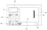
図1(A)、(B)に電子装置システムの一例である車載システム1の外観を示す。図1(A)、(B)に示すように車載システム1は、車両に搭載される車載機器100(電子装置)と、ナビゲーション機能を備えたポータブル機器10(ポータブル電子装置)とから構成される。ポータブル機器10は、図1(A)に示すように車載機器100の前面部120(蓋部材)に取り付けて使用したり、図1(B)に示すように車載機器100から取り外して使用することができる。
1A and 1B show the appearance of an in-
車載機器100は、ラジオ放送の再生機能や、CD(Compact Disc)等の記録媒体に書き込まれた音楽データを再生可能な機器であり、CD再生部やCD挿排口を有する車載機器本体110と、表示部131や操作部132を有する前面部120とを備えている。
The in-
ポータブル機器10は、目的地までの誘導経路を検索し、地図上に検索した誘導経路を重ねて表示するナビゲーションの機能を備えている。
The
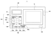
図2は、ポータブル機器10を車載機器100から取り外した状態を示す。車載機器100の前面部120には、ポータブル機器10を装着するための凹部が形成された着脱部170が設けられている。この着脱部170には、車載機器100とポータブル機器10とを電気的に接続するためのコネクタ150と、ポータブル機器10を前面部120に固定するためのロック機構(不図示)が設けられている。前面部120に設けた取り外しボタン160を操作すると、不図示のロック機構が解除され、車載機器100からポータブル機器10が取り外し可能となる。
FIG. 2 shows a state where the
図3には、前面部120を車載機器本体110に対して傾斜させ、CD挿排口180を露出させた状態を示す。
FIG. 3 shows a state in which the
不図示の駆動機構によって図3に示すスライダー181を駆動させることで、前面部120を車載機器本体110に対してチルト(傾斜)させることができる。チルト動作によって、車載機器本体110に設けられたCD挿排口180を露出させてCDの挿排を行ったり、車載機器100の表示部131や、ポータブル機器10の表示部11を視認し易いように調整することができる。車載機器100の前面部120には、操作ボタン(図6に示すチルト/イジェクトボタン132a)が設けられており、このボタンの操作に応じたチルト角度に設定することができる。
By driving the
図4は、車載システム1の車両への搭載例を示す。
FIG. 4 shows an example of mounting the in-
車載システム1は、例えば図4に示すように、運転席52と助手席51とのほぼ中央のダッシュボード部分に配置される。
For example, as shown in FIG. 4, the in-
尚、図示していないが、後述するGPS情報受信部133のGPSアンテナは、ダッシュボード上に配置されているか、又はフロントガラスの車室内側に貼り付けられる。
Although not shown, a GPS antenna of a GPS
図5は、車載システム1の概略構成を示すブロック図である。
FIG. 5 is a block diagram illustrating a schematic configuration of the in-
車載機器100とポータブル機器10とは、コネクタで電気的に接続される。車載機器100側には、コネクタ150が設けられており、ポータブル機器10には、コネクタ30が設けられている。これらのコネクタ150、30を接続することで、車載機器100とポータブル機器10との間で各種信号が送受信されて車載システム1として機能する。また、コネクタ150、30には、車両のバッテリからの電力をポータブル機器10に供給するための電力供給端子が設けられており、ポータブル機器10が車載機器100に接続された状態で、車載機器100に電力が供給されていると、電力供給端子を介してポータブル機器10にも電力が供給される。
The in-
車載機器100は、表示部131、操作部132、GPS情報受信部133、ラジオ受信部134、CD再生部135、音声調整部136、メモリ137、マイク138、外部音声/映像入力部139、制御部140(制御手段)、コネクタ150を備えている。車載機器100は、エンジンキーがAcc又はONの位置にあるときに、車両側のバッテリから電力を供給されて動作する。
The in-
以下、各部の機能の詳細について説明する。 Details of the functions of the respective units will be described below.
表示部131は、液晶パネルやバックライトを備え、13セグメント表示によって受信放送周波数、再生楽曲トラックNo、再生楽曲名等を表示する。操作部132は、車載機器100の動作モードを切り換えるための操作や、切り換えた各種モードでの操作を行うためのものである。操作部132には、図6に示すようにチルト/イジェクトボタン132a、ファンクション(以下、FUNCと表記する)(又はFUNC/AF)ボタン132b、TEXT(又はTEXT/TP)ボタン132c、SCREENボタン132d、SOURCE/PWRボタン132e、MODE(又はMODE/PTY)ボタン132f、MUTEボタン132g、BAND切換ボタン132h、ロータリーボタン132i、十字キー/エンターキーボタン132jとからなるボタン群を備える。
The
ここで、ボタン群の操作による制御について説明する。 Here, the control by the operation of the button group will be described.
まず、SOURCE/PWRボタン132eの操作によるポータブル機器10と車載機器100の表示の切り替えについて説明する。
First, switching of display between the
まず、車載機器100のSOURCE/PWRボタン132eを押下することで、車載機器100がオンされる。また車載機器100がオンしているときに、SOURCE/PWRボタン132eを短押しすることでCD再生やラジオ等のソースの移行が行われる。このとき、車載機器100の表示部131には、選択されたソースにおける情報が表示され、ポータブル機器10の表示部11には、ソースに関係なくナビゲーション画像が表示される。
First, the in-
次に、SCREENボタン132dを押下すると、ポータブル機器10の表示部11の表示をナビゲーション画像から車載機器100で選択されたソースに対応する画像に切り換えることができる。
Next, when the
図7(A)は車載機器100でCDを再生中にポータブル機器10を装着し、ポータブル機器10でナビゲーション画像を表示している状態を示している。
FIG. 7A shows a state in which the
図7(A)の状態から、SOURCE/PWRボタン132eを押下して、CD再生からラジオのソースに切換操作を行うと、図7(B)に示すように、表示部131にラジオソースにおける情報が表示される。また、ポータブル機器10の表示部11には、ナビゲーション画像が表示されたままである。
When the SOURCE /
次に、ユーザがSCREENボタン132dを押下すると、図7(C)に示すようにポータブル機器10の表示部11に、車載機器100で処理中のソースに対応する画像が表示される(図7(C)ではラジオ画像)。ポータブル機器10の表示部11には、後述するタッチパネルが設けられており、ユーザはタッチパネルを介して表示部11に表示される操作ボタンを選択することで、現在処理中のソースに対する操作をすることができる。
Next, when the user presses the
また、表示部11にラジオ画像が表示された状態で、SCREENボタン132dを押下すると、図7(D)に示すようにラジオ画面からナビゲーション画像に戻ることができる。ポータブル機器10が車載機器100から取り外されている状態では、SCREENボタン132dの操作は無効となる。
Further, when the
また、ポータブル機器10が車載機器100から取り外されている状態で、外部音声/映像入力部139にUSB(Universal Serial Bus)等が接続された場合には、SOURCE/PWRボタン132eを押下しても、USBのソースには切り換わらないようにすることもできる。
Further, when a USB (Universal Serial Bus) or the like is connected to the external audio /
次に、チルト/イジェクトボタン132aの操作による前面部120のチルト動作について説明する。
Next, the tilting operation of the
チルト/イジェクトボタン132aが第1の態様(例えば、短押し)で操作されると、前面部120は、CD挿排口180が露出される角度まで、前面部120がチルトされ、第2の態様(例えば、長押し)で操作されると、所定角度づつ前面部120がチルトする。
When the tilt /
図5に戻って、GPS情報受信部133は、GPSアンテナとチューナ部とを有し、衛星からのGPS信号を受信する。GPS情報受信部133で受信したGPS信号は、制御部140、コネクタ150、コネクタ30及び制御部20を介してポータブル機器10のナビゲーション部19に出力され、GPS信号に基づいてポータブル機器10が装着された車載機器100が搭載される車両の位置が割り出される。
Returning to FIG. 5, the GPS
尚、GPS情報受信部133で受信したGPS信号を制御部20を介さずに、制御部20を介してポータブル機器10のナビゲーション部19に出力するようにしてもよいし、GPS情報受信部133をGPSアンテナのみで構成し、GPSアンテナで受信したGPS信号を、制御部140及び制御部20を介さず、後述するGPS情報受信部13のチューナに出力するようにしてもよいし、制御部20は介するが、制御部140を介さずGPS情報受信部13のチューナに出力するようにしてもよい等、適宜変更が可能である。
Note that the GPS signal received by the GPS
ラジオ受信部134は、アンテナ134aとチューナ部134bとを有しており、アンテナ134aは、AM放送、FM放送、多重放送等の放送波を受信し、チューナ部134bは、アンテナ134で受信した放送波を復調し、音声信号や多重信号等の復調信号を制御部140に出力する。
The
CD再生部135は、CDに記録されたデータを再生し、再生信号を制御部140に出力する。尚、チューナ部134bから出力される復調信号を制御部140を介さずに、後述する音声調整部136に出力するようにしてもよい。
The
音声調整部136は、ラジオ受信部134で受信、復調された音声信号や、CD再生部135で再生された音声信号に、音量調整や音質調整等の信号処理をしてスピーカ145に出力する。
The
メモリ137(記憶手段)は、データの読み出しと書き込みとが可能なRAM(Random Access Memory)で構成することができ、制御のために必要な情報、例えば、後述する地域情報と、ボタンに割り当てられている機能等とを関連づけたテーブル情報等を記憶している。マイク138は、ハンズフリー通話を行うためのものであって、車室内のユーザの音声を取り込む。
The memory 137 (storage means) can be composed of a RAM (Random Access Memory) capable of reading and writing data, and is assigned to information necessary for control, for example, regional information to be described later and buttons. The table information etc. which linked | related with the function etc. which have been stored are memorize | stored. The
外部音声/映像入力部139は、USBメモリや、携帯型オーディオ装置等の外部機器との接続端子を備え、外部機器からの音声信号やデータを入力して制御部140に送り、制御部140からの制御信号、音声信号、データ等を接続した外部機器に出力する。
The external audio /
制御部140(取得手段、切換手段)は、操作部132の操作に従って、ラジオ受信部134、CD再生部135、音声調整部136などを制御する。
The control unit 140 (acquisition unit, switching unit) controls the
また、制御部140は、コネクタ150を介してポータブル機器10に各種信号を出力し、ポータブル機器10から入力した各種信号に基づいて車載機器100を制御する。例えば、制御部140は、GPS情報受信部133で受信したGPS信号や、マイク138で入力された音声信号を、コネクタ150を介してポータブル機器10に出力する。尚、マイク138で入力された音声信号を、制御部140を介さずに、コネクタ150を介してポータブル機器10に出力してもよい。また、制御部140は、ポータブル機器10と接続された携帯電話からの通話音声をコネクタ150を介して入力し、音声調整部136を介してスピーカ145に出力する。
Further, the
さらに、制御部140は、ポータブル機器10の表示部11に表示される、各種モードのメニュー画像に対する操作信号をポータブル機器10の制御部20から取得し、ラジオ受信部134やCD再生部135の制御を行う。
Further, the
また、制御部140には、車両に搭載されたバッテリからの電源が入力されている。制御部140は、ポータブル機器10が接続されている場合に、バッテリの電源をポータブル機器10に出力する。また、制御部140には、車両から車速パルスとイルミ電源信号が入力される。制御部140は、入力した車速パルスをポータブル機器10の制御部20に転送する。尚、車速パルスが入力されない構成でもよい。
In addition, the
次に、ポータブル機器10について説明する。ポータブル機器10は、表示部11、操作部12、GPS情報受信部13、スピーカ14、蓄電池15、充電回路16、無線通信送受信部17、メモリ18、ナビゲーション部19、制御部20、読取部21、及びコネクタ30を備えている。
Next, the
以下、各部の機能の詳細について説明する。 Details of the functions of the respective units will be described below.
表示部11は、液晶パネルとバックライトとを備え、ナビゲーション部19で生成された地図情報や目的地までの誘導経路情報、また車載機器100から転送された受信放送周波数、再生楽曲トラックNo、再生楽曲名等を表示することができる。表示部11、131には、液晶パネル以外のフラットパネルディスプレイ、例えば、有機ELディスプレイパネル、プラズマディスプレイパネル、冷陰極フラットパネルディスプレイ等を用いることができる。
The
操作部12は、タッチパネルや、ポータブル機器10の電源をオン、オフするための電源ボタン55(図8(A)参照)を含む。タッチパネルは、例えば、表示部11の表示画面の上に配置されるものであり、指や専用のペンによりタッチパネルが接触されると、その接触された位置が検知されて、入力操作の有無が判別できるようになっている。電源ボタン55については後述する。
The
GPS情報受信部13は、アンテナとチューナ部とを有しており、衛星からのGPS信号を受信する。受信したGPS信号はナビゲーション部19に出力され、GPS信号に基づいて自車位置が割り出される。なお、車載装置100にもGPS情報受信部133が設けられているが、車載機器100にポータブル機器10が取り付けられているときには、GPS情報受信部133で受信したGPS信号(及び車速パルス)を用いてポータブル機器10が収納された車載機器100が搭載される車両の位置を特定し、ポータブル機器10単独で使用する場合には、GPS情報受信部13で受信したGPS信号を用いて自機位置を特定する。
The GPS
スピーカ14は、ナビゲーション部19からの音声情報を出力するためのものであり、ポータブル機器10が車載機器100から取り外された状態、つまり単体で使用されるときに、音声情報を出力する。
The
蓄電池15は、ポータブル機器10の各部に電力を供給する。またポータブル機器10を車載機器100に装着すると、コネクタ30の電力供給端子を介して車両のバッテリから電力が供給され、充電回路16によって蓄電池15を充電する。また、充電回路16はUSBスロット(図8(A)参照)を介して接続端末から電力の供給を受けて、蓄電池15を充電することができる。
The
無線通信送受信部17は、携帯電話との間で通話音声の送受信を行ったり、携帯電話を介してナビゲーションに利用する情報を取得する。無線通信送受信部17には、例えば、2.4GHz帯域の無線伝送方式である、Bluetoothが用いられる。 The wireless communication transmitting / receiving unit 17 transmits / receives call voice to / from a mobile phone or acquires information used for navigation via the mobile phone. For the wireless communication transmitter / receiver 17, for example, Bluetooth, which is a wireless transmission system of 2.4 GHz band, is used.
メモリ18は、例えば読み出しと書き込みとが可能なRAMであり、各制御のために読み出された情報を一時的に記憶しておく。
The
ナビゲーション部19は、ナビゲーションのために利用される地図情報を記憶した後述するSDカードやUSBメモリ等で構成される可搬性記憶媒体(地域情報記憶手段)から取得し、記憶する地図情報記憶部を備え、GPS情報受信部133、又は13からのGPS信号によって現在位置情報を割り出し、ナビゲーション動作のための画像を作成する。作成した地図は、表示部11で表示させることができる。また、車載機器100とポータブル機器10とが接続されている場合には、車両から車速パルスを取得して、ポータブル機器10が収納された車載機器100が搭載される車両の位置検出の精度を高めることができる。
The
尚、地図情報はポータブル機器10内のメモリ18等に保持していてもよい。この場合、地図情報が記憶されるメモリが地域情報記憶手段に相当する。
The map information may be held in the
制御部20は、ポータブル機器10の各部を制御する。また、制御部20は、コネクタ30を介して車載機器100に各種信号を出力し、車載機器100から入力した各種信号に基づいてポータブル機器10を制御する。例えば、制御部20は、車載機器100のGPS情報受信部133で受信したGPS信号、及び車速パルスを車載機器100の制御部140から取得し、ナビゲーション部19に出力する。また、制御部20は、車載機器100のマイク138で入力した音声信号を車載機器100の制御部140から取得し、音声信号に応じてナビゲーション部19を制御する。すなわち、ナビゲーション部19をハンズフリーで操作することができる。また、無線通信送受信部17にて接続された携帯電話からの通話音声を、コネクタ30を介して車載機器側に出力し、車載機器100のスピーカ145から出力させる。また、表示部11に表示されたメニュー画面やコンテンツ画面に対する操作信号をコネクタ30を介して車載機器100の制御部140に出力する。制御部140は、ポータブル機器10の制御部20から送られた操作信号に応じて、ラジオ受信部134やCD再生部135を制御する。
The
読取部21は、後述するSD(Secure Digital)メモリカードスロット56やUSBスロット57を備えている(図8(A)参照)。読取部21は、SDメモリカードスロット56に差し込まれたSDカードやUSBスロット57に差し込まれたUSBメモリから地図情報などを読み取る。
The reading unit 21 includes an SD (Secure Digital)
図8(A)に、ポータブル機器10の正面図、上面図、下面図、左側面図、右側面図を示し、図8(B)にポータブル機器10の背面図を示す。
8A shows a front view, a top view, a bottom view, a left side view, and a right side view of the
ポータブル機器10の上面には、ポータブル機器の電源をオン、オフさせる電源ボタン55が設けられており、下面には、SD(Secure Digital)メモリカードスロット56、USBスロット57が設けられている。地図情報が記憶されたSDカードやUSBメモリをこれらのスロットに差し込むことで、制御部20は、SDカードやUSBメモリから地図情報を読み出し、ナビゲーション部19に地図情報を出力する。
A
ポータブル機器10の電源は、ポータブル機器を車載機器100に装着したときには、車載機器100からの制御によって電源がオン、オフされる。また、車載機器100から取り外してポータブル機器10を単体で使用する場合には、電源ボタン55のオン、オフ操作に基づいて電源が操作される。
When the
さらに、ポータブル機器10の背面側には、車載機器100との電気的な接続をとるためのコネクタ30と、車載機器100側に設けたロック機構(不図示)と係合する係合部58とが設けられている。
Furthermore, on the back side of the
図9は、図1(A)で示した車載機器100およびポータブル機器10の外観の模式図に相当する実際の外観図である。図1(B)と同じ構成は同じ番号を付し説明を省略する。
FIG. 9 is an actual external view corresponding to the schematic external view of the in-
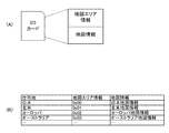
図10(A)は、SDメモリカードスロット56に差し込まれるSDカードに記録された情報の概略構成を示し、図10(B)は仕向地、地図エリア情報及び地図情報の関係を示す図である。
FIG. 10A shows a schematic configuration of information recorded on an SD card inserted into the SD
図10(A)に示すように、SDカードには、地図エリア情報(地域情報)及び地図情報が1つづつ記録されている。地図エリア情報は、記録されている地図情報の地域を示す情報である。また、図10(B)に示すように、地図エリア情報は「0x00」のような1バイトのデータで構成されており、例えば、仕向地が北米の場合には、SDカードは、地図エリア情報として「0x01」を、地図情報として「北米地図情報」を記録している。尚、図9(B)の例では、仕向地が日本、北米、ヨーロッパ、及びオーストラリアの例を示したが、中国、韓国、南米などの他の国や地域の地図エリア情報及び地図情報をSDカードに記録してもよい。 As shown in FIG. 10A, map area information (region information) and map information are recorded one by one on the SD card. The map area information is information indicating the area of the recorded map information. As shown in FIG. 10B, the map area information is composed of 1-byte data such as “0x00”. For example, when the destination is North America, the SD card stores the map area information. "0x01" is recorded as the map information, and "North America map information" is recorded as the map information. In the example of FIG. 9B, the destinations are shown in Japan, North America, Europe, and Australia. However, the map area information and map information of other countries and regions such as China, South Korea, and South America are SD. It may be recorded on a card.
また、地図エリア情報及び地図情報は、インターネット等を介してダウンロードすることにより、書き換えることも可能である。つまり、使用する地域の地図エリア情報及び地図情報をダウンロードしてSDカードの情報を書き換えることにより、使用する地域を変更してもナビゲーション機能を実現できる。 Further, the map area information and the map information can be rewritten by downloading via the Internet or the like. That is, by downloading the map area information and map information of the area to be used and rewriting the information on the SD card, the navigation function can be realized even if the area to be used is changed.
図11は、車載機器100のメモリ137が備えるテーブル情報の一例を示す図である。
FIG. 11 is a diagram illustrating an example of table information included in the
このテーブル情報は、地図エリア情報、周波数帯、シーク(seek)ステップ、シーク感度、プリセットチャンネル(CH)及びボタンに割り当てる機能の項目で構成されている。周波数帯の項目には、各地図エリア情報に対応するAM及びFMのラジオの周波数帯が記録されている。 This table information is composed of map area information, frequency band, seek step, seek sensitivity, preset channel (CH), and function items assigned to buttons. In the frequency band item, AM and FM radio frequency bands corresponding to each map area information are recorded.
シークステップの項目には、1ステップ毎に増減する周波数の数値が記録されている。例えば、同図において、地図エリア情報が「0x00」であり且つ周波数帯が「AM:522−1629kHz」のシークステップは「9kHz」であり、これは、図6の十字キー/エンターキーボタン132jの右側を押下する度に、受信するラジオの周波数が9kHz増加すること及び図6の十字キー/エンターキーボタン132jの左側を押下する度に、受信するラジオの周波数が9kHz減少することを示している。この増減する9kHz幅の周波数帯に放送局の周波数が含まれる場合には、ラジオ受信部134がその放送局から発信される電波を受信する。
In the item of the seek step, a numerical value of a frequency that increases or decreases for each step is recorded. For example, in the figure, the seek step when the map area information is “0x00” and the frequency band is “AM: 522-1629 kHz” is “9 kHz”, which is the result of the cross key /
シーク感度の項目は、「AUTO」又は「FIX」の文字が記録されている。「AUTO」は、電波を受信するモードを自動で切り換えることを示す。電波を受信するモードは、近距離の放送局から発信される電波を受信するローカルモードと遠距離の放送局から発信される電波を受信するDxモードとがある。「FIX」は電波を受信するモードがDxモードに固定されていることを示す。 In the item of seek sensitivity, characters “AUTO” or “FIX” are recorded. “AUTO” indicates that the mode for receiving radio waves is automatically switched. The mode for receiving radio waves includes a local mode for receiving radio waves transmitted from short-distance broadcast stations and a Dx mode for receiving radio waves transmitted from long-distance broadcast stations. “FIX” indicates that the radio wave receiving mode is fixed to the Dx mode.
プリセットCHの項目は、各チャンネルのボタンに割り当てられている周波数が記録されている。チャンネルのボタンは図7(C)に示すように、タッチパネル式のポータブル機器10の表示部11に表示される。
In the preset CH item, the frequency assigned to the button of each channel is recorded. The channel button is displayed on the
ボタンの割り当て機能の項目は、各ボタンに割り当てられる機能が記録されている。つまり、地図エリア情報が「0x00」では、FUNCボタン132bはFUNC切換(機能の切換)を指示するためのボタンとなるが、地図エリア情報が「0x02」では、FUNCボタン132bが、FUNC/AFボタン132bとなり、短押(例えば、1.7秒未満)の操作ではFUNC(例えば、オートプリセットモード、スキャンモード等)切換を指示し、長押(例えば、1.7秒以上)の操作ではAFサーチ(ネットワークフォロー)を指示するためのボタンとなる。また、地図エリア情報が「0x00」では、TEXTボタン132cはCDのTEXT情報等の表示情報の切換を指示するためのボタンとなるが、地図エリア情報が「0x02」では、TEXTボタン132cが、TEXT/TPボタン132cとなり、短押(例えば、1.7秒未満)の操作ではTPモード(交通情報受信待受モード)を指示し、長押(例えば、1.7秒以上)の操作ではCDのTEXT情報等の表示情報の切換を指示するためのボタンとなる。さらに、地図エリア情報が「0x00」では、MODEボタン132fは車載機器100のMODE(例えば、プリセットCH選択モード、選局モード)のON/OFFを指示するためのボタンとなるが、地図エリア情報が「0x02」では、MODEボタン132fが、MODE/PTYボタン132fとなり、短押(例えば、1.7秒未満)の操作ではMODEのON/OFFを指示し、長押(例えば、1.7秒以上)の操作ではPTYサーチのためのPTYコードを選択するためのボタンとなる。
In the button assignment function item, a function assigned to each button is recorded. That is, when the map area information is “0x00”, the
尚、地図エリア情報、周波数帯、シークステップ、シーク感度、プリセッCH、及びボタンに割り当てられる機能の項目は、操作部12又は操作部132を利用して、編集することができる。また、各地図エリア情報に対応して割り当てられる項目、及び各項目に割り当てられる数値、機能等はこれに限定されるものではない。
Note that the map area information, frequency band, seek step, seek sensitivity, preset CH, and function items assigned to the buttons can be edited using the
図12は、車載機器100の制御部140が実行する設定切換処理を示すフローチャートである。
FIG. 12 is a flowchart showing a setting switching process executed by the
制御部140が、車載機器100の電源がON状態になったことを検出すると、図12の処理が開示され、車載機器100の電源がON状態の間、本処理を繰り返す。
When the
まず、制御部140は、ポータブル機器10の車載機器100への装着状態の変化を判別する(ステップS1)。装着状態の変化の判別方法は、具体的には、制御部140が制御部20に対して接続信号を定期的に又は任意のタイミングで送信し、制御部140が、前回の送信時には制御部20からレスポンスを受信していたが、今回の送信時には制御部20からレスポンスを受信しない場合には、ポータブル機器10が車載機器100から取り外された(装着→非装着)と判断し、逆に、前回の送信時には制御部20からレスポンスを受信していなかったが、今回の送信時には制御部20からレスポンスを受信した場合には、ポータブル機器10が車載機器100に装着された(非装着→装着)と判断する。
First, the
尚、装着状態の変化の判別方法は、前述の取り外しボタン160の操作状態を検出したり、装着状態の変化を検出するための構成を別途設ける等、適宜変更可能である。
It should be noted that the method for determining the change in the mounting state can be changed as appropriate, such as detecting the operation state of the above-described
制御部140は、ステップS1において、装着状態が装着から非装着に変化、又は変化無と判別した場合には、ステップS1を繰り返し、装着状態が非装着から装着に変化したと判別した場合には、ポータブル機器10の制御部20に対してSDカードに記録されている地図エリア情報の送信を要求し(ステップS2)、ポータブル機器10の制御部20から地図エリア情報を取得できるまで待機する(ステップS3)。
When it is determined in step S1 that the wearing state has changed from wearing to non-wearing or no change, the
ポータブル機器10の制御部20は、車載機器100の制御部140からの地図エリア情報の送信要求を受けて、読取部21を介してSDカードに記録されている地図エリア情報を読み出して、制御部140に送信する。
The
制御部140は、ポータブル機器10の制御部20から地図エリア情報を取得すると、メモリ137に記憶されている地図エリア情報と、ポータブル機器10の制御部120から取得した地図エリア情報を比較する(ステップS4)。尚、出荷時には、メモリ137に前述の比較のための地図エリア情報が記憶されていないものとする。
When acquiring the map area information from the
制御部140は、ポータブル機器10の制御部20から取得した地図エリア情報と、メモリ137に記憶されている比較のための地図エリア情報とが異なる場合には、メモリ137に記憶されている図11に示すテーブル情報に含まれる地図エリア情報のうち、取得した地図エリア情報と一致する地図エリア情報を確定し、現在の操作部132及びチューナ部134bの設定をこの確定された地図エリア情報に対応する、新たな操作部132及びチューナ部134bの設定に切り換え、メモリ137に、確定した地図エリア情報を前述の比較のための地図エリア情報として記憶し(ステップS5)、ステップS1に戻る。操作部132及びチューナ部134bの設定とは、ボタンに割り当てられた機能の設定及びラジオ機能の設定であり、具体的には、図7(C)のチャンネルのボタン(プリセットボタン)に割り当てられた周波数の設定、及び図11のAM/FMラジオの周波数帯、シークステップ、シーク感度、及びボタンに割り当てられる機能等の設定である。
When the map area information acquired from the
また、制御部140が、ステップS4において、ポータブル機器10の制御部20から取得した地図エリア情報と、メモリ137に記憶されている比較のための地図エリア情報とが一致する場合には、ステップS1に戻る。
If the
尚、取得した地図エリア情報と、メモリ137に記憶している比較用の地図エリア情報の比較を行わず、取得した地図エリア情報に基づいて、機能等の設定を行うようにしてもよい。この場合は、メモリ137に比較用の地図エリア情報を記憶する必要はない。また、出荷時にメモリ137に仕向先の地図エリア情報を記憶させておくと共に、ボタン等の設定を仕向先に対応する設定としてもよい。
It should be noted that settings such as functions may be set based on the acquired map area information without comparing the acquired map area information with the comparison map area information stored in the
以上詳細に説明したように、本実施例によれば、ポータブル機器10の装着が検出された場合に、制御部140は、自動的にポータブル機器10に差し込まれたSDカードに含まれる地図エリア情報の送信を要求して、ポータブル機器10から地図エリア情報を受信し、受信された地図エリア情報に応じて車載機器100の機能の設定を切り換えるので、ユーザに煩雑な操作をさせることなく、各地域に応じた機能の設定を行うことができる。
As described above in detail, according to the present embodiment, when the attachment of the
また、地図エリア情報と、ラジオ機能の設定と、ボタンに割り当てられる機能の設定とを関連付けてテーブル情報としてメモリ137に記憶し、取得した地図エリア情報と上記テーブル情報内の地図エリア情報とが一致する場合に、現在の機能の設定が、当該一致した地図エリア情報に対応する、ラジオ機能の設定及びボタンに割り当てられる機能等の設定に切り換えられるので、ユーザに煩雑な操作をさせることなく、各地域に応じた、ラジオ機能の設定及びボタンに割り当てられる機能の設定を行うことができる。
Further, the map area information, the radio function setting, and the function setting assigned to the button are associated with each other and stored as table information in the
さらに、ラジオ機能の設定は、AM/FMラジオの周波数帯、シークステップ及びシーク感度の設定を含み、ボタンに割り当てられる機能の設定は、チャンネルのボタンに割り当てられた周波数の設定や、各地域特有の機能の設定等を含むので、ユーザに煩雑な操作をさせることなく、各地域に応じた、AM/FMラジオの周波数帯、シークステップ及びシーク感度の設定、プリセットチャンネルに割り当てられる周波数の設定、ボタンに割り当てられる機能の設定等を行うことができる。 Furthermore, the radio function settings include AM / FM radio frequency band, seek step and seek sensitivity settings, and the function settings assigned to the buttons are the frequency settings assigned to the channel buttons and each region specific. Function settings, etc., so that the user does not have to perform complicated operations, the AM / FM radio frequency band, seek step and seek sensitivity settings, frequency settings assigned to preset channels, The function assigned to the button can be set.
また、地図エリア情報は、記憶されている地図情報の地域を示す情報であるので、ユーザに煩雑な操作をさせることなく、ナビゲーション機能で使用される地図情報の地域に応じた機能の設定を行うことができる。 Further, since the map area information is information indicating the area of the stored map information, the function is set according to the area of the map information used in the navigation function without causing the user to perform complicated operations. be able to.
上記実施例では、地図エリア情報に対応する仕向地は、日本、北米、ヨーロッパ、及びオーストラリア等の国や地域であったが、東京、大阪、ニューヨーク、パリ、及びシドニーなどの都市でもよい。 In the above embodiment, the destination corresponding to the map area information is a country or region such as Japan, North America, Europe, and Australia, but may be a city such as Tokyo, Osaka, New York, Paris, and Sydney.
また、本実施例では、SDカードが地図エリア情報及び地図情報を含んでいたが、地図エリア情報及び地図情報を含む記憶媒体は、これに限定されず、USBメモリやコンパクトフラッシュ(登録商標)などポータブル機器10で読み取り可能な記憶媒体であればよいし、ポータブル機器10内に地図エリア情報及び地図情報を記憶するハードディスクを備える構成であってもよい。
In this embodiment, the SD card includes the map area information and the map information. However, the storage medium including the map area information and the map information is not limited to this, and a USB memory, a compact flash (registered trademark), etc. Any storage medium that can be read by the
また、本実施例では、ポータブル機器10の制御部20を介して地図エリア情報を取得するようにしていたが、制御部140が直接取得するようにしてもよい。さらに、ポータブル機器10がポータブルナビゲーターである例について説明したが、本発明は、これに限られず、ナビゲーション機能付携帯電話、ナビゲーション機能付携帯端末(PDA)等であってもよい。
Further, in the present embodiment, the map area information is acquired via the
上記実施例では、ラジオ受信部の設定変更について説明したが、設定変更される対象は、これに限定されるものではない。 In the above-described embodiment, the setting change of the radio reception unit has been described. However, the setting change target is not limited to this.
本実施例では、ポータブル機器10と車載機器100とからなる車載システム1について説明したが、ポータブル機器10を備えず、車載機器100単体で機能するナビゲーション装置であってもよく、この場合は、当該ナビゲーション装置が使用する地図ディスク(CD、DVD)や、ハードディスク等に地図エリア情報及び地図情報を記録し、ナビゲーション装置の制御部が地図ディスクやハードディスクに記録されている地図エリア情報を取得する構成にすることにより、地図ディスクを変更する、又はハードディスクを交換する若しくは書き換えることで、本実施例と同様に効果が得られる。
In this embodiment, the in-
また、ナビゲーション機能を備える携帯機器単体でも、内部に備えたり、装着される、地図情報が記録されるメモリ等に、地図情報と共に地図エリア情報を書き換え可能に記録しておけば、前述のナビゲーション装置と同様に、本実施例と同様の効果が得られる。 In addition, even if a portable device having a navigation function is used alone, if the map area information and the map area information are recorded in a rewritable memory or the like that is provided inside or attached to the map, the navigation device described above can be used. Similarly to the above, the same effect as in the present embodiment can be obtained.
更に、CD挿排口及びCD再生部の代わりに、MD、DVD、SDカード等の他の記憶媒体の挿排口及び再生部を設ける構成にしてもよいし、複数種の記憶媒体の挿排口及び再生部を設ける構成にしてもよい。 Further, instead of the CD insertion / extraction port and the CD reproduction unit, another storage medium insertion / extraction unit and reproduction unit such as MD, DVD, SD card, etc. may be provided. You may make it the structure which provides a mouth and a reproduction | regeneration part.
本実施例では、1つのボタンに複数の機能を割り当てているが、各ボタンに1つの機能を割り当てるようにしてもよい。また、地図エリア情報を取得するタイミング、機能の設定を変更するタイミング等は、適宜変更可能である。 In this embodiment, a plurality of functions are assigned to one button, but one function may be assigned to each button. The timing for acquiring the map area information, the timing for changing the function settings, and the like can be changed as appropriate.
車載機器100の機能を実現するためのソフトウェアのプログラムが記録されている記録媒体を、車載機器100に供給し、車載機器100のコンピュータ(即ち、制御部140)が記憶媒体に格納されたプログラムを読み出し実行することによっても、上記実施例と同様の効果を奏する。プログラムを供給するための記憶媒体としては、例えば、CD−ROM、DVD、及びSDカードなどがある。
A recording medium in which a software program for realizing the function of the in-
また、車載機器100のコンピュータ(即ち、制御部140)が、車載機器100の機能を実現するためのソフトウェアのプログラムを実行することによっても、上記実施例と同様の効果を奏する。
In addition, the same effect as in the above-described embodiment can be obtained when the computer of the in-vehicle device 100 (that is, the control unit 140) executes a software program for realizing the function of the in-
上述した実施例は本発明の好適な実施の一例である。但し、これに限定されるものではなく、本発明の要旨を逸脱しない範囲内において種々変形実施可能である。 The above-described embodiment is an example of a preferred embodiment of the present invention. However, the present invention is not limited to this, and various modifications can be made without departing from the scope of the present invention.
10 ポータブル機器
18 メモリ
19 ナビゲーション部
20 制御部
21 読取部
100 車載機器
132 操作部
134 ラジオ受信部
135 CD再生部
137 メモリ(記憶手段)
140 制御部(取得手段、切換手段)
DESCRIPTION OF
140 Control unit (acquisition means, switching means)
Claims (7)
前記地域情報記憶手段から前記地域情報を取得する取得手段と、
前記取得手段により取得した地域情報に応じて機能の設定を切り換える切換手段と
を備えることを特徴とする電子装置。 In an electronic device in which a portable electronic device equipped with a regional information storage means in which regional information is stored can be mounted,
Obtaining means for obtaining the area information from the area information storage means;
An electronic apparatus comprising: switching means for switching function settings according to the area information acquired by the acquisition means.
前記切換手段は、前記ボタンに割り当てられる機能の設定を、前記取得手段により取得した地域情報と、前記記憶手段に記憶された地域情報とが一致する機能の設定に切り換えることを特徴とする請求項1記載の電子装置。 Storage means for storing the area information and the function setting assigned to the button in association with each other;
The switching means switches a function setting assigned to the button to a function setting in which the area information acquired by the acquisition means matches the area information stored in the storage means. The electronic device according to 1.
前記切換手段は、前記ラジオ機能の設定を、前記取得手段により取得した地域情報と、前記記憶手段に記憶された地域情報とが一致する機能の設定に切り換えることを特徴とする請求項1又は2に記載の電子装置。 Storage means for associating and storing regional information and radio function settings;
The switching means switches the radio function setting to a function setting in which the area information acquired by the acquiring means matches the area information stored in the storage means. An electronic device according to 1.
前記地域情報は、前記ナビゲーション機能で使用される地図情報の地域を示す情報であることを特徴とする請求項1乃至4のいずれか1項記載の電子装置。 The portable electronic device is a portable navigator having a navigation function,
5. The electronic apparatus according to claim 1, wherein the area information is information indicating an area of map information used in the navigation function.
前記ポータブル電子装置が装着可能な電子装置とを備え、
前記電子装置は、
前記地域情報記憶手段から前記地域情報を取得する取得手段と、
前記取得手段により取得した地域情報に応じて機能の設定を切り換える切換手段と
備えることを特徴とする電子装置システム。 A portable electronic device comprising regional information storage means for storing regional information;
An electronic device to which the portable electronic device can be attached,
The electronic device is
Obtaining means for obtaining the area information from the area information storage means;
An electronic device system comprising switching means for switching function settings in accordance with area information acquired by the acquisition means.
前記地域情報記憶手段から前記地域情報を取得する取得手段と、
前記取得手段により取得した地域情報に応じて機能の設定を切り換える切換手段と
を備えることを特徴とする電子装置。
Area information storage means for storing area information;
Obtaining means for obtaining the area information from the area information storage means;
An electronic device comprising: switching means for switching function settings according to the area information acquired by the acquisition means.
Priority Applications (2)
| Application Number | Priority Date | Filing Date | Title |
|---|---|---|---|
| JP2007026202A JP2008191016A (en) | 2007-02-05 | 2007-02-05 | Electronic device and electronic device system |
| PCT/JP2008/051759 WO2008096704A1 (en) | 2007-02-05 | 2008-02-04 | Electronic device and electronic device system |
Applications Claiming Priority (1)
| Application Number | Priority Date | Filing Date | Title |
|---|---|---|---|
| JP2007026202A JP2008191016A (en) | 2007-02-05 | 2007-02-05 | Electronic device and electronic device system |
Publications (2)
| Publication Number | Publication Date |
|---|---|
| JP2008191016A true JP2008191016A (en) | 2008-08-21 |
| JP2008191016A5 JP2008191016A5 (en) | 2010-12-24 |
Family
ID=39681613
Family Applications (1)
| Application Number | Title | Priority Date | Filing Date |
|---|---|---|---|
| JP2007026202A Pending JP2008191016A (en) | 2007-02-05 | 2007-02-05 | Electronic device and electronic device system |
Country Status (2)
| Country | Link |
|---|---|
| JP (1) | JP2008191016A (en) |
| WO (1) | WO2008096704A1 (en) |
Cited By (5)
| Publication number | Priority date | Publication date | Assignee | Title |
|---|---|---|---|---|
| JP2010085207A (en) * | 2008-09-30 | 2010-04-15 | Fujitsu Ten Ltd | Navigation device |
| KR101017950B1 (en) | 2008-12-10 | 2011-03-02 | 재단법인대구경북과학기술원 | Exterior Electronic Control Unit Apparatus, and Method, Apparatus and Vehicle for Extending Electronic Control Unit with The Same |
| KR101091675B1 (en) | 2010-06-22 | 2011-12-08 | 현대자동차주식회사 | Method for management electronic unit of vehicle using usb |
| US8175804B2 (en) | 2009-01-26 | 2012-05-08 | Denso Corporation | Navigation apparatus |
| KR101335223B1 (en) | 2011-10-21 | 2013-11-29 | 주식회사 현대케피코 | Reprogramming method of electronic control unit for vehicle and reprogramming electronic control unit |
Citations (2)
| Publication number | Priority date | Publication date | Assignee | Title |
|---|---|---|---|---|
| JPH10150375A (en) * | 1996-11-15 | 1998-06-02 | Alpine Electron Inc | On-vehicle equipment |
| JP2003032083A (en) * | 2001-07-19 | 2003-01-31 | Kenwood Corp | On-vehicle receiver, reception operation setting method and program |
Family Cites Families (4)
| Publication number | Priority date | Publication date | Assignee | Title |
|---|---|---|---|---|
| JPH05347540A (en) * | 1990-12-28 | 1993-12-27 | Nissan Shatai Co Ltd | Automatic radio channel selection preset device |
| JP4775618B2 (en) * | 2004-03-19 | 2011-09-21 | 株式会社デンソー | Airbag system setting switching device |
| JP4396656B2 (en) * | 2005-04-21 | 2010-01-13 | 株式会社デンソー | Map display apparatus and vehicle navigation apparatus equipped with the apparatus |
| JP4476185B2 (en) * | 2005-06-27 | 2010-06-09 | 三洋電機株式会社 | BROADCAST RECEIVING APPARATUS, AUTOMOBILE HAVING THE SAME, AND PROGRAM FOR CAUSING COMPUTER TO EXECUTE OPERATION |
-
2007
- 2007-02-05 JP JP2007026202A patent/JP2008191016A/en active Pending
-
2008
- 2008-02-04 WO PCT/JP2008/051759 patent/WO2008096704A1/en active Application Filing
Patent Citations (2)
| Publication number | Priority date | Publication date | Assignee | Title |
|---|---|---|---|---|
| JPH10150375A (en) * | 1996-11-15 | 1998-06-02 | Alpine Electron Inc | On-vehicle equipment |
| JP2003032083A (en) * | 2001-07-19 | 2003-01-31 | Kenwood Corp | On-vehicle receiver, reception operation setting method and program |
Cited By (6)
| Publication number | Priority date | Publication date | Assignee | Title |
|---|---|---|---|---|
| JP2010085207A (en) * | 2008-09-30 | 2010-04-15 | Fujitsu Ten Ltd | Navigation device |
| US8896550B2 (en) | 2008-09-30 | 2014-11-25 | Fujitsu Ten Limited | Navigation system |
| KR101017950B1 (en) | 2008-12-10 | 2011-03-02 | 재단법인대구경북과학기술원 | Exterior Electronic Control Unit Apparatus, and Method, Apparatus and Vehicle for Extending Electronic Control Unit with The Same |
| US8175804B2 (en) | 2009-01-26 | 2012-05-08 | Denso Corporation | Navigation apparatus |
| KR101091675B1 (en) | 2010-06-22 | 2011-12-08 | 현대자동차주식회사 | Method for management electronic unit of vehicle using usb |
| KR101335223B1 (en) | 2011-10-21 | 2013-11-29 | 주식회사 현대케피코 | Reprogramming method of electronic control unit for vehicle and reprogramming electronic control unit |
Also Published As
| Publication number | Publication date |
|---|---|
| WO2008096704A1 (en) | 2008-08-14 |
Similar Documents
| Publication | Publication Date | Title |
|---|---|---|
| JP4934014B2 (en) | In-vehicle electronic device and in-vehicle electronic system | |
| KR100912880B1 (en) | In-vehicle electronic apparatus and in-vehicle electronic system | |
| JP2009035024A (en) | On-board electronic system and device | |
| JP5008408B2 (en) | Electronic device and electronic system | |
| JP2008162578A (en) | Electronic equipment and electronic system | |
| JP2008164603A (en) | Electronic device and electronic system | |
| JP2008162579A (en) | Electronic equipment and electronic system | |
| JP4842848B2 (en) | Electronic device and electronic system | |
| KR100911677B1 (en) | Electronic apparatus, electronic system and method of controlling audio output | |
| JP4751875B2 (en) | Electronic device, electronic system, and audio output control method | |
| JP2008191016A (en) | Electronic device and electronic device system | |
| KR20080063074A (en) | Electronic system, electronic apparatus and method of operating audio unit | |
| JP2008162576A (en) | Electronic equipment and electronic system | |
| WO2009125611A1 (en) | Electronic device | |
| EP1931045B1 (en) | In-vehicle electronic apparatus and in-vehicle electronic system | |
| JP5154111B2 (en) | Electronic equipment cover | |
| CN102056768B (en) | Vehicle-mounted device | |
| JP2008168713A (en) | In-vehicle equipment | |
| JP5042642B2 (en) | Electronic equipment | |
| JP2008306411A (en) | Electronic apparatus, portable apparatus, and electronic system | |
| US8294598B2 (en) | Electronic apparatus and electronic system | |
| JP2008298651A (en) | Electronic device and electronic system | |
| JP2008304278A (en) | Electronic device and electronic system | |
| JP2008162577A (en) | Electronic equipment and electronic system | |
| JP2008247365A (en) | Electronic equipment |
Legal Events
| Date | Code | Title | Description |
|---|---|---|---|
| A621 | Written request for application examination |
Free format text: JAPANESE INTERMEDIATE CODE: A621 Effective date: 20100120 |
|
| A521 | Written amendment |
Free format text: JAPANESE INTERMEDIATE CODE: A523 Effective date: 20101105 |
|
| A131 | Notification of reasons for refusal |
Free format text: JAPANESE INTERMEDIATE CODE: A131 Effective date: 20110830 |
|
| A02 | Decision of refusal |
Free format text: JAPANESE INTERMEDIATE CODE: A02 Effective date: 20120110 |