JP2008178564A - Electric vacuum cleaner - Google Patents
Electric vacuum cleaner Download PDFInfo
- Publication number
- JP2008178564A JP2008178564A JP2007014439A JP2007014439A JP2008178564A JP 2008178564 A JP2008178564 A JP 2008178564A JP 2007014439 A JP2007014439 A JP 2007014439A JP 2007014439 A JP2007014439 A JP 2007014439A JP 2008178564 A JP2008178564 A JP 2008178564A
- Authority
- JP
- Japan
- Prior art keywords
- suction port
- unit
- vacuum cleaner
- power supply
- control signal
- Prior art date
- Legal status (The legal status is an assumption and is not a legal conclusion. Google has not performed a legal analysis and makes no representation as to the accuracy of the status listed.)
- Pending
Links
Images



Landscapes
- Electric Vacuum Cleaner (AREA)
Abstract
【課題】掃除機本体から吸込口体あるいは連通管の電源部に供給する電圧波形を利用して制御部に制御信号を送ることができ、しかも制御信号の伝達を確実に行うことができる電気掃除機を提供する。
【解決手段】吸込口体5には、回転清掃体18を回転させる吸込口モータ13が設けられている。吸込口モータ13は、吸込口電源部48を電源として動作し、手元操作管12の操作ボタン11によって動作が指示される。掃除機本体1から吸込口体5に電力を供給する電力線16には、抵抗70が接続されている。吸込口制御部52は、双方向性サイリスタ39によって制御され、掃除機本体1から電力線14、16を介して電源検出部54に入力される制御信号に基づき吸込口モータ13を制御する。抵抗70が設けられているので、吸込口モータ70が駆動していないときでも、電力が消費されて双方向性39のオン状態を保持する保持電流が流れ、確実に制御信号を伝達できる。
【選択図】図4An electric cleaning device that can send a control signal to a control unit using a voltage waveform supplied from a vacuum cleaner body to a suction port body or a power supply unit of a communication pipe, and can reliably transmit the control signal. Provide a machine.
The suction port body 5 is provided with a suction port motor 13 for rotating a rotary cleaning body 18. The suction port motor 13 operates with the suction port power supply 48 as a power source, and the operation is instructed by the operation button 11 of the hand operation tube 12. A resistor 70 is connected to the power line 16 that supplies power from the cleaner body 1 to the suction port 5. The suction port control unit 52 is controlled by the bidirectional thyristor 39 and controls the suction port motor 13 based on a control signal input from the cleaner body 1 to the power source detection unit 54 via the power lines 14 and 16. Since the resistor 70 is provided, even when the suction port motor 70 is not driven, a holding current that maintains the ON state of the bidirectionality 39 flows because power is consumed, and the control signal can be reliably transmitted.
[Selection] Figure 4
Description
本発明は、吸込口体あるいは連通管に、掃除機本体から電源が供給される動作部とその動作部を制御する制御部とを備えた電気掃除機に関する。 The present invention relates to an electric vacuum cleaner including an operation part to which power is supplied from a vacuum cleaner main body and a control unit for controlling the operation part on a suction port body or a communication pipe.
従来の電気掃除機として、例えば特許文献1に記載された電気掃除機が知られている。この電気掃除機は、例えばホースに、このホース内の2本の配線を介して掃除機本体から電源が供給される手元回路部が設けられている。手元回路部は、表示や報知などの出力を行う出力手段を備えている。一方、掃除機本体には、ゴミ量検出手段とこのゴミ量検出手段が検出したゴミ量に応じた本体情報を配線に出力する信号送信手段とが設けられている。
As a conventional vacuum cleaner, for example, a vacuum cleaner described in
そして、ゴミ量に応じて電源電圧を制御することによって本体情報を手元回路部に送信する。手元回路部は制御された電源電圧を検出して、その検出結果を出力手段に出力し、出力手段は本体情報を表示あるいは報知する。この電気掃除機によれば、ホースの配線を増やすことなく手元回路部への電源供給と信号の送信とを行うことができる。
上記特許文献1には、掃除機本体から手元回路部へ供給される電源の電圧波形を用いて信号を送信するという技術思想は開示されているものの、これを実現する具体的構成は開示されていない。本出願の発明者が電源の電圧波形を信号として利用することについて検討を重ねたところ、交流電源の電圧波形を容易に制御するために双方向性サイリスタを用いると、以下に述べるような課題が生じることが判明した。
Although the technical idea of transmitting a signal using the voltage waveform of the power source supplied from the cleaner body to the hand circuit unit is disclosed in
双方向性サイリスタは、通常モータ等の負荷の電力を制御する目的で使用されるものであり、その場合、制御端子に制御信号を供給すればオンし、その後負荷により電力が消費される。そのため、双方向性サイリスタを継続して動作させるために必要な保持電流が流れ、電源電圧が反転するまで導通させることができる。一方、電源の電圧波形を信号として利用する場合には、モータ等の負荷が動作していない状態でも双方向性サイリスタを制御する場合が生じる。この場合、制御端子への制御信号により双方向性サイリスタはオンするが、接続されている負荷が軽負荷で充分な電流が流れず、電源電圧が反転するまで導通状態を維持できないというおそれがあり、結果として、信号として用いられる電源の電圧波形の信頼性が低下するという問題が生じる。 The bidirectional thyristor is usually used for the purpose of controlling the power of a load such as a motor. In this case, the control thyristor is turned on when a control signal is supplied to the control terminal, and then the power is consumed by the load. For this reason, a holding current necessary for continuously operating the bidirectional thyristor flows and can be conducted until the power supply voltage is inverted. On the other hand, when the voltage waveform of the power supply is used as a signal, the bidirectional thyristor may be controlled even when a load such as a motor is not operating. In this case, the bidirectional thyristor is turned on by the control signal to the control terminal, but there is a risk that the connected load is light and sufficient current does not flow, and the conduction state cannot be maintained until the power supply voltage is reversed. As a result, there arises a problem that the reliability of the voltage waveform of the power supply used as the signal is lowered.
そこで、本発明は上記課題を解決し、電源の電圧波形を信号として利用することができ、しかも確実に信号伝達が行える電気掃除機を得ることを目的とする。 SUMMARY OF THE INVENTION Accordingly, an object of the present invention is to solve the above-described problems and to obtain a vacuum cleaner that can use a voltage waveform of a power supply as a signal and can reliably transmit a signal.
上記目的を達成するために本発明は、電動送風機を備えた掃除機本体と、この掃除機本体に接続され電力線が配設された連通管と、この連通管に接続され電動送風機の動作により塵埃を吸い込む吸込口体と、この吸込口体に設けられるとともに電力線を介して掃除機本体から交流電圧が印加されて電力が供給される電源部と、吸込口体に設けられ電源部により動作する動作部とを有し、掃除機本体に、電力線に接続される双方向性サイリスタとこの双方向性サイリスタに制御信号を出力する制御信号出力部とを備えて掃除機本体から電源部に印加する交流電圧波形を制御する本体制御部を設け、吸込口体に、本体制御部で制御された交流電圧波形に基づいて動作部を制御する制御部を設けた電気掃除機であって、動作部の非動作状態で掃除機本体から電源部への電力を消費する負荷を電力線に接続したものである。 In order to achieve the above object, the present invention provides a vacuum cleaner body provided with an electric blower, a communication pipe connected to the vacuum cleaner body and provided with a power line, and an operation of the electric blower connected to the communication pipe to generate dust. Suction port body, a power supply unit provided in the suction port body and supplied with an AC voltage from the cleaner body via a power line, and an operation provided by the power supply unit provided in the suction port body And the vacuum cleaner main body is provided with a bidirectional thyristor connected to the power line and a control signal output unit for outputting a control signal to the bidirectional thyristor. A vacuum cleaner provided with a main body control unit for controlling a voltage waveform, and a suction port body provided with a control unit for controlling the operation unit based on an AC voltage waveform controlled by the main body control unit. Vacuum cleaner in operating state The load that consumes power from the body to the power supply unit which are connected to the power line.
本発明によれば、掃除機本体から供給される電圧波形を利用して本体制御部から制御部に制御信号を送ることができ、さらに信号伝達の信頼性を高めることができる。 ADVANTAGE OF THE INVENTION According to this invention, a control signal can be sent to a control part from a main body control part using the voltage waveform supplied from a cleaner body, and also the reliability of signal transmission can be improved.
以下、本発明の第一の実施の形態を、図面を参照して説明する。 Hereinafter, a first embodiment of the present invention will be described with reference to the drawings.
はじめに、図1、図2および図3を用いて、電気掃除機の構成を説明する。電気掃除機は、掃除機本体1と、この掃除機本体1に形成された吸込口2に一端が着脱可能に接続されるホース3と、このホース3の他端に一端が着脱可能に接続される延長管4と、この延長管4の他端に着脱可能に接続される吸込口本体5とからなる。ホース3と延長管4とで連通管6が構成される。
First, the configuration of the electric vacuum cleaner will be described with reference to FIGS. 1, 2, and 3. The vacuum cleaner has a
掃除機本体1は、電動送風機7、吸込口2を介してホース3と連通する集塵部としての集塵袋8を内部に設け、電動送風機7の吸気風が集塵袋8内を通過することでこの集塵袋8で塵埃を分離し集塵するようになっている。さらに、本体1の前側下面には旋回自在な旋回輪(図示せず)を、本体1の後側側面には大径の一対の従動後輪9(一方のみ図示)をそれぞれ設けている。
The vacuum cleaner
ホース3は、伸縮自在で湾曲可能な略円筒状からなるもので、ハンドル10と電動送風機7の入力等を設定する操作ボタン11とを備えた手元操作管12(手元操作部)を有している。この操作ボタン11は、電動送風機7、吸込口モータ13をそれぞれ異なる駆動状態にする複数種類の運転モードを選択することができるように構成されている。具体的には、図中に示すように、ホース3から延長管4の方向に向けて、電動送風機7の停止設定用の操作ボタン11a、電動送風機7の強入力/弱入力の運転設定用の操作ボタン11b、吸込口モータ13の正転/反転/停止の運転設定用の操作ボタン11cが一列に順次並んで配設されている。
The
また、ホース3には、電動送風機7の電源例えば交流電源と吸込口体5とを接続するための一対の電力線14が設けられている。さらに、ホース3には、掃除機本体1に設けられた後述する本体制御部と手元操作部12とを接続する一対の信号線15が設けられている。信号線15の1本は電力線14を共用している。そして、これら電力線14と信号線15とは、ホースの3の一端から他端にわたって配設されている。
Further, the
延長管4は大径管4aとこの大径管4a内に挿入される小径管4bからなり、小径管4bを大径管4aに対してスライドさせることで延長管4全体を伸縮可能にしている。これら大径管4aと小径管4bとには一対の電力線16が設けられ、この電力線16はホース3に設けられた電力線14と接続されている。
The extension pipe 4 includes a
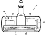
次に、吸込口体5の構成について詳述する。吸込口体5は、この延長管4の先端に着脱可能に取り付けられるもので、被掃除面上の塵埃を吸い込む吸込開口5aを設けている。図2は、吸込口体5の構成を掃除面(底面)側から見た様子を示す平面図である。図2に示すように、吸込口体5には動作部としての吸込口モータ13が配設されており、この吸込口モータ13の回転は、動力伝達機構17により回転清掃体18に伝達されるようになっている。吸込口体5の掃除面(底面)側には、吸込口モータ13の安全スイッチとして機能する掃除面スイッチ19が配設されている。なお、吸込口体5内には、吸込口体制御装置60を実装した吸込口回路基板21が組み込まれている。
Next, the configuration of the suction port body 5 will be described in detail. The suction port body 5 is detachably attached to the distal end of the extension pipe 4 and is provided with a suction opening 5a for sucking dust on the surface to be cleaned. FIG. 2 is a plan view showing the configuration of the suction port body 5 as viewed from the cleaning surface (bottom surface) side. As shown in FIG. 2, a
次に、掃除機本体1に内蔵された本体制御部30、吸込口体5に内蔵された吸込口制御装置60を含む回路構成を図3に基づいて説明する。31は商用交流電源で、本体制御部30において、制御信号で駆動されるスイッチング素子、例えば、双方向性サイリスタ32、電流ヒューズ33、および電動送風機7の一部を構成し交流電源で駆動される整流子モータ(以下、単にモータという)34が直列に接続されている。
Next, a circuit configuration including the main
電動送風機7は、主にモータ34とこのモータ34で回転されるファン35とから構成されている。モータ34は、例えば、ブラシ(図示せず)と、このブラシに摺動する整流子を備えた電機子34aと界磁巻線34b,34cとから構成されるユニバーサルモータである。ファン35はモータ34の回転軸に接続された遠心型ファンであり、モータ34によりファン35が回転すると、塵埃を含んだ空気が吸込口体5から延長管4、ホース3を介して掃除機本体1に吸い込まれる。36はゼロクロス検出部で、モータ34に印加する交流電源電圧のゼロクロスポイントを検出する。
The
また、37はマイクロコンピュータからなり制御信号出力部を構成する本体制御装置で、そのI/O部38には、手元操作管12に接続された信号線15が接続され、手元操作管12からは指示信号等がI/O部38に入力される。そして、本体制御装置37は、商用交流電源31のゼロクロスタイミングの取込み、手元操作管12からの指示信号等の取込みを行うとともに、双方向性サイリスタ32、および電力線14に接続された電力制御素子としての双方向性サイリスタ39の制御端子に制御信号を出力するようになっている。
Reference numeral 37 denotes a main body control device comprising a microcomputer and constituting a control signal output unit. The signal line 15 connected to the
さらに、交流電源31と吸込口体5に設けられた後述する電源部とを接続する一対の電力線間には抵抗素子で構成された負荷70が設けられている。この負荷70は、前記電源部と並列接続されるものであり、本実施の形態では掃除機本体1内に設けられているが、電力線14、16のいずれに設けてもよい。負荷70は、その冷却という観点からみれば電動送風機7により生ずる風路中に配置されることが望ましい。
Furthermore, a
また、手元操作管12の各操作ボタン11a〜11cとそれぞれ直列に設けられた抵抗部品12a〜12cは、それぞれ異なる抵抗値となっており、本体電源部40の出力電圧の分圧値を操作ボタン11の操作状態に応じて変化させるための回路構成(電圧可変回路)をなしている。そして、操作ボタン11の操作状態に応じて変動する分圧値を、本体制御装置37が周期的に読み取る。
Further, the resistance components 12a to 12c provided in series with the
本体制御装置37は、主に、中央処理部41、メモリ42、前述したI/O部38、およびタイマ43などから構成される。メモリ42は、中央処理部41が実行する制御プログラム、ならびに必要な定数などのデータが予め記憶しており、また、中央処理部41の演算データなどを一時記憶しておくデータ記憶領域ならびに作業領域として使用される。
The main body control device 37 mainly includes a central processing unit 41, a
44は電動送風機7に流れる電流を検出する電流検出部で、この電流検出部44の出力は本体制御装置37に入力される。本体制御装置37は、電流検出部44の出力に応じて掃除機本体1に設けられた図示しない報知部を動作させる。これにより、集塵袋8の集塵量に関する情報が使用者に知らされる。
Reference numeral 44 denotes a current detection unit that detects a current flowing through the
次に、吸込口体5に設けられた吸込口制御装置60の構成を説明する。商用交流電源31に双方向性サイリスタ39を介して、電源部としての吸込口電源部48が接続されている。この双方向性サイリスタ39の制御信号の出力タイミングは、前述したように本体制御装置37が制御する。吸込口電源部48は、電力線16に接続される整流部48a、降圧部48b、定電圧部48cなどから構成されている。整流部48aは例えばダイオードから構成され、定電圧部48cは例えば電解コンデンサから構成されている。整流部48aには、トランジスタ等の4つのスイッチング素子49a〜49dから構成されるブリッジ回路49が接続され、さらに、このブリッジ回路49に吸込口モータ13が接続されている。また、吸込口電源部48は、制御部としての吸込口制御部50の電源としても機能する。
Next, the structure of the suction inlet control apparatus 60 provided in the suction inlet body 5 is demonstrated. A suction port
吸込口制御部50は、主に、メモリ51、中央処理部52、I/O部(図示せず)、およびタイマ53から構成される。メモリ51は、吸込口体5に設けられた動作部の動作に係る制御プログラム、ならびに必要な定数などのデータが予め記憶されている。この吸込口制御部50には、電源検出部54が接続される。
The
吸込口制御部50には、電源検出部54から、掃除機本体1より吸込口電源部48に供給される交流電圧波形の情報、換言すれば信号が入力される。そして、この波形情報に応じて、ブリッジ回路49の各スイッチング素子49a〜49dへオン、オフの制御信号を出力して、吸込口モータ13の回転速度や回転方向を制御する。例えば、吸込口制御部50が、スイッチング素子49aと49dをオンさせた場合は、掃除面に対して吸込口体5が前方向に進むように回転(正転)し、逆に、スイッチング素子49bと49cをオンさせた場合は、掃除面に対して吸込口体5が後方向に進むように回転(反転)する。
Information on the AC voltage waveform supplied from the power
なお、本体制御装置37は、コンセントが差し込まれて商用電源から電源が供給されると双方向性サイリスタ39の制御端子に所定のタイミングで制御信号を供給して、吸込口体5の電源部48に電力を供給する。これにより、吸込口制御部50は電源が供給されて動作可能となる。このとき、吸込口制御部50はブリッジ回路49の各スイッチング素子49a〜49dに対して何ら出力しない。
The main body control device 37 supplies a control signal to the control terminal of the bidirectional thyristor 39 at a predetermined timing when an outlet is inserted and power is supplied from a commercial power supply, and the
このような構成において、手元操作管12の操作ボタン11が操作されると、この操作に基づいた信号が本体制御装置37に入力される。電動送風機7を動作させる旨の信号である場合には、本体制御装置37から双方向性サイリスタ32の制御端子に制御信号が供給され、電動送風機7が駆動される。本体制御装置37は、位相制御により電動送風機7の入力を可変できる。
In such a configuration, when the
また、操作ボタン11Cが操作されて、吸込口体5の動作部である吸込口モータ13を動作させる旨の信号が本体制御装置37に入力されると、本体制御装置37は双方向性サイリスタ39の制御端子に例えば図4の(e)に示すタイミング、すなわち電源電圧のゼロクロスタイミングから時間tb後に制御信号を供給する。この時点では吸込口モータ13は動作していないが、電力線14、14間に抵抗70が接続されているため、掃除機本体1から吸込口体5に供給される電力が消費されて双方向性サイリスタ39にその保持電流以上の電流が流れる。したがって、双方向性サイリスタ39は電源電圧が反転するまで確実に導通するので、吸込口体端子の間すなわち電力線16には図4の(f)に示す電圧が発生する。なお、この制御信号の出力タイミングは操作ボタン11Cの操作に基づいて予め定められたものであり、上述したような電源投入時に吸込口制御部50を動作可能とするために制御信号を供給する場合とは容易に区別が可能となるような異なるタイミングに設定されている。また、電圧波形は、図4の(f)に示すように手元操作部12の操作ボタン11Cが操作されてから次の操作があるまで同じとする、すなわち制御信号を出し続けるようにしてもよいし、操作ボタン11Cが操作されてから所定期間のみその操作に応じた電圧波形とし、その後は図4の(a)に示される交流電源の電圧波形とする、すなわち所定期間のみ制御信号を出力してもよい。なお、この場合、電源検出部54が所定期間に電圧波形を検出し、その電圧波形を吸込口電源検出信号に変換して吸込口制御部50に出力する。そして、吸込口制御部50は吸込口電源検出信号に応じて吸込口モータ13を制御する。その後、電源検出部54は、交流電源の電圧波形を検出して、その旨の吸込口電源検出信号を吸込口制御部50に対して出力する。そして、吸込口制御部50は吸込口モータ13が従前の状態を維持するように制御する。
When the
ここで、図4の(f)において、点線で示している電圧波形は、負荷70が接続されていない場合に、吸込口体端子間に発生する電圧波形である。これは、吸込口モータ13が動作していない状態では電力線に接続されている負荷が吸込口制御部50を構成するマイクロコンピュータ等の軽負荷だけであることから、双方向性サイリスタ39に流れる電流がある時点で保持電流以下となってしまうためである。吸込口電源部48への電源波形を信号として利用する構成の場合、上記点線部の電圧波形は、電源検出部54が電圧波形を吸込口電源検出信号に変換する際に大きな誤差要因となる等、信号の伝達に悪影響を与える。
Here, in FIG. 4F, the voltage waveform indicated by the dotted line is a voltage waveform generated between the suction port terminals when the
しかしながら、上記構成によれば、交流電源31と吸込口電源部48とを接続する一対の電力線間に負荷70が設けられているため、この負荷70によって、掃除機本体1からの電力が消費されて双方向性サイリスタ39にその保持電流以上の充分な電流が流れる。このため、双方向性サイリスタ39は電源電圧が反転するまで導通し、図4に示されたtdの期間の吸込口体端子間電圧は、実質的に図4(f)に実線で示される電圧波形となり、双方向性サイリスタ39によって制御される電圧波形に与える影響を極力抑えることができる。したがって、吸込口モータ13が非動作状態であっても、吸込口体5の電源検出部54が本体制御部30で制御される電源の電圧波形を確実に受信することができる。なお、上述のとおり、吸込口モータ13が動作しているときには双方向性サイリスタ39にその保持電流が流れることから、上記の負荷70は少なくとも吸込口モータ13が動作していないときに電力線に接続されるようになっていればよい。
However, according to the above configuration, since the
そして、操作ボタン11Cが再度操作されると本体制御装置37は、図4(e)に示す出力タイミングとは異なるタイミングで双方向性サイリスタ39に制御信号を出力する。これに基づいて吸込口制御部50は、吸込口モータ13を例えば反転させるように制御する。その後、もう一度操作ボタン11Cが操作されると同様にして吸込口モータ13は停止するよう制御される。
When the operation button 11C is operated again, the main body control device 37 outputs a control signal to the bidirectional thyristor 39 at a timing different from the output timing shown in FIG. Based on this, the suction
上述したとおりであるから、電源検出部54は、双方向性サイリスタ39に流れる電流不足による電圧波形への悪影響が抑制された図4の(f)に実線で示す電圧波形を、図4の(g−1)または(g−2)に示す吸込口電源の検出信号に変換し、この検出信号を吸込口制御部50に出力することができる。吸込口制御部50は、図4(g−1)の検出信号の場合、そのハイレベル期間tdあるいはローレベル期間tcを検出して、その検出結果に応じて吸込口モータ13を所定の状態、例えばスイッチング素子49a、49dをオンにして正転させる。また、吸込口制御部50は、図4(g−2)の検出信号の場合、その電圧値Vsを測定し、この測定値に応じて同様に吸込口モータ13を制御する。
Since it is as above-mentioned, the power
以上説明したように本実施の形態の電気掃除機によれば、掃除機本体1から供給される吸込口モータ13の電源の電圧波形を利用して、吸込口モータ13等の動作部を制御することができる。しかも、交流電源31と吸込口電源部48とを接続する一対の電力線間に負荷70を設けたことから、確実に双方向性サイリスタ39にその保持電流を流すことができ、信号伝達の信頼性低下を抑制することができる。また、この負荷70を掃除機本体1内に設けたことから、吸込口体5が大型化することを抑えることができ、さらには負荷70を電動送風機7によって流れる風の風路中に配置することで発熱する負荷70を効率よく冷却することができ、発熱に対する安全性が向上する。
As described above, according to the electric vacuum cleaner of the present embodiment, the operation unit such as the
次に本発明の第二の実施の形態を図5に基づいて説明する。上記第一の実施の形態と同様の構成については説明を省略する。本実施の形態においては、図3に示される負荷70は設けられていない。そして、双方向性サイリスタ39が不用意にオフしないようにする手段として、第一の実施の形態においては、電源線14に負荷70を接続したものであるのに対し、本実施の形態においては、本体制御装置37による制御信号の制御を工夫したものである。
Next, a second embodiment of the present invention will be described with reference to FIG. The description of the same configuration as that of the first embodiment is omitted. In the present embodiment, the
操作ボタン11Cが操作されて、吸込口体5の動作部である吸込口モータ13を動作させる旨の信号が本体制御装置37に入力されると、本体制御部37は双方向性サイリスタ39の制御端子に例えば図5の(e)に示すように制御信号を出力する。すなわち、本体制御部37は、制御信号の立ち上がり時点から交流電源電圧波形が次のゼロクロスポイントに至る時点まで制御信号を実質的に出力し続ける。本実施の形態では、ゼロクロスポイントの時間tb後から次のゼロクロスポイントの直前までの期間制御信号を出力し続けるものである。これにより、電力線14、16に接続される負荷に係わらず、この期間は双方向性サイリスタ39は導通状態を保つことができる。
When the
このため、吸込口端子間電圧の波形は図5の(f)に示すものとなり、電源検出部54が出力する吸込口電源検出信号は図5の(g−1)となる。吸込口制御部50は、検出信号のハイレベル期間teあるいはローレベル期間tfを検出して、その検出結果に応じて吸込口モータ13を所定の状態、例えばスイッチング素子49a、49dをオンにして正転させる。
Therefore, the waveform of the voltage between the suction port terminals is as shown in FIG. 5F, and the suction port power supply detection signal output from the power
なお、吸込口モータ13が動作状態にあるときは双方向性サイリスタ39にその保持電流以上の電流が流れることから、吸込口端子間電圧はゼロクロスポイントより時間tb経過した時点から次のゼロクロスポイントまで電圧が生じ、したがって、電源検出部54が出力する吸込口電源検出信号も時間teよりも長くなる。しかしながら、吸込口制御部50はこれを時間teと同等に判断し、スイッチング素子49a、49dをオンにして吸込口モータ13を正転させるようになっている。
In addition, when the
以上説明したように本実施の形態の電気掃除機によれば、第一の実施の形態と同様に、吸込口モータ13等の動作部を制御することができる。しかも、本体制御部37は、制御信号の立ち上がり時点から交流電源電圧波形が次のゼロクロスポイントに至る時点まで制御信号を実質的に出力し続けるので、不用意に双方向性サイリスタ39がオフすることが防止でき、信号伝達の信頼性低下を抑制することができる。
As described above, according to the vacuum cleaner of the present embodiment, the operation unit such as the
本実施の形態においては、本体制御装置37は、ゼロクロスポイントより時間tb経過した時点から次のゼロクロスポイントに至る前までの期間制御信号を出力し続けるようにしたが、当然に、次のゼロクロスポイントに至る時点まで信号を出力し続けてもよい。ただし、本実施の形態のように制御信号を次のゼロクロスポイントまで出力し続けないようにすることによって、以下に述べるように更なる利点がある。すなわち、本体制御装置37が制御信号の立ち上がり時点から次のゼロクロスポイントまで制御信号を出力し続けるようにする場合、本体制御部30のゼロクロス検出部36で検出誤差が生じると、ゼロクロスポイントを超えた時点まで制御信号が出力されるおそれがあるが、本実施の形態のものではそのようなおそれは少ない。したがって、信号伝達の信頼性低下をより抑制することができる。
In the present embodiment, the main body control device 37 continues to output the control signal for a period from the time point tb after the zero cross point until the next zero cross point is reached. The signal may continue to be output until the point in time. However, there is a further advantage as described below by not outputting the control signal until the next zero cross point as in the present embodiment. That is, when the main body control device 37 continues to output the control signal from the rising point of the control signal to the next zero cross point, if a detection error occurs in the zero cross detection section 36 of the main
上記各実施の形態においては、動作部を吸込口体5に設けたものについて説明したが連通管6に設けてもよく、この場合は掃除機本体1からの電圧波形を検出する電源検出部および動作部を制御する制御部50も連通管6に設ければよい。例えば、電流検出部44の検出結果に基づいてゴミ詰まり状況を表示する表示部等を連通管6の手元操作管12に設けることが考えられる。このように連通管6に動作部および電源検出部を設けた場合でも、上記各実施の形態と同様の効果を奏することができる。
In each of the above-described embodiments, the operation unit provided in the suction port body 5 has been described. However, the operation unit may be provided in the communication pipe 6. In this case, a power source detection unit that detects a voltage waveform from the
1 掃除機本体
5 吸込口体
6 連通管
7 電動送風機
13 吸込口モータ(動作部)
14 電力線
16 電力線
30 本体制御部
37 本体制御装置(制御信号出力部)
39 双方向性サイリスタ
48 吸込口電源部(電源部)
50 吸込口制御部(制御部)
54 電源検出部(検出部)
DESCRIPTION OF
14 Power line 16
39
50 Suction port control unit (control unit)
54 Power supply detection unit (detection unit)
Claims (4)
前記掃除機本体に、前記電力線に接続される双方向性サイリスタとこの双方向性サイリスタに制御信号を出力する制御信号出力部とを備えて前記掃除機本体から前記電源部に印加する交流電圧波形を制御する本体制御部を設け、
前記吸込口体に、前記本体制御部で制御された交流電圧波形に基づいて前記動作部を制御する制御部を設けた電気掃除機であって、
前記動作部の非動作状態で前記掃除機本体から前記電源部への電力を消費する負荷を前記電力線に接続したことを特徴とする電気掃除機。 A vacuum cleaner body provided with an electric blower, a communication pipe connected to the vacuum cleaner body and provided with a power line, a suction port body connected to the communication pipe and sucking dust by operation of the electric blower, and the suction port A power supply unit that is provided on the body and supplied with power by applying an AC voltage from the cleaner body through the power line, and an operation unit that is provided on the suction port body and operates by the power supply unit,
An AC voltage waveform applied from the cleaner body to the power supply unit, comprising a bidirectional thyristor connected to the power line and a control signal output unit for outputting a control signal to the bidirectional thyristor in the cleaner body. A main body control unit for controlling
A vacuum cleaner provided with a control unit for controlling the operation unit based on an AC voltage waveform controlled by the main body control unit in the suction port body,
A vacuum cleaner, wherein a load that consumes power from the vacuum cleaner main body to the power supply unit is connected to the power line in a non-operating state of the operation unit.
前記掃除機本体に、前記電力線に接続される双方向性サイリスタとこの双方向性サイリスタに制御信号を出力する制御信号出力部とを備えて前記掃除機本体から前記電源部に印加する交流電圧波形を制御する本体制御部を設け、
前記連通管に、前記本体制御部で制御された交流電圧波形に基づいて前記動作部を制御する制御部を設けた電気掃除機であって、
前記動作部の非動作状態で前記掃除機本体から前記電源部への電力を消費する負荷を前記電力線に接続したことを特徴とする電気掃除機。 A vacuum cleaner body provided with an electric blower, a communication pipe connected to the vacuum cleaner body and provided with a power line, a suction port connected to the communication pipe and sucking dust by operation of the electric blower, and the communication pipe And a power supply unit to which power is supplied by applying an AC voltage from the vacuum cleaner body via the power line, and an operation unit that is provided in the communication pipe and operates by the power supply unit,
An AC voltage waveform applied from the cleaner body to the power supply unit, comprising a bidirectional thyristor connected to the power line and a control signal output unit for outputting a control signal to the bidirectional thyristor in the cleaner body. A main body control unit for controlling
A vacuum cleaner provided with a control unit for controlling the operation unit based on an AC voltage waveform controlled by the main body control unit in the communication pipe,
A vacuum cleaner, wherein a load that consumes power from the vacuum cleaner body to the power supply unit is connected to the power line in a non-operating state of the operation unit.
前記掃除機本体に、前記電力線に接続される双方向性サイリスタとこの双方向性サイリスタに制御信号を出力する制御信号出力部とを備えて前記掃除機本体から前記電源部に印加する交流電圧波形を制御する本体制御部を設け、
前記吸込口体に、前記本体制御部で制御された交流電圧波形に基づいて前記動作部を制御する制御部を設けた電気掃除機であって、
前記制御信号出力部は、前記動作部の非動作状態で、前記制御信号の立上がりの時点から前記交流電圧波形が次のゼロクロスポイントに至る時点まで制御信号を実質的に出力し続けることを特徴とする電気掃除機。 A vacuum cleaner body provided with an electric blower, a communication pipe connected to the vacuum cleaner body and provided with a power line, a suction port body connected to the communication pipe and sucking dust by the operation of the electric blower, and the suction port A power supply unit that is provided on the body and supplied with power by applying an AC voltage from the cleaner body through the power line, and an operation unit that is provided on the suction port body and operates by the power supply unit,
An AC voltage waveform applied from the cleaner body to the power supply unit, comprising a bidirectional thyristor connected to the power line and a control signal output unit for outputting a control signal to the bidirectional thyristor in the cleaner body. A main body control unit for controlling
A vacuum cleaner provided with a control unit for controlling the operation unit based on an AC voltage waveform controlled by the main body control unit in the suction port body,
The control signal output unit continues to substantially output the control signal from the time when the control signal rises until the time when the AC voltage waveform reaches the next zero cross point in a non-operating state of the operation unit. Electric vacuum cleaner.
前記掃除機本体に、前記電力線に接続される双方向性サイリスタとこの双方向性サイリスタに制御信号を出力する制御信号出力部とを備えて前記掃除機本体から前記電源部に印加する交流電圧波形を制御する本体制御部を設け、
前記連通管に、前記本体制御部で制御された交流電圧波形に基づいて前記動作部を制御する制御部を設けた電気掃除機であって、
前記制御信号出力部は、前記動作部の非動作状態で、前記制御信号の立上がりの時点から前記交流電圧波形が次のゼロクロスポイントに至る時点まで制御信号を実質的に出力し続けることを特徴とする電気掃除機。 A vacuum cleaner main body provided with an electric blower, a communication pipe connected to the vacuum cleaner main body and provided with a power line, a suction port connected to the communication pipe and sucking dust by operation of the electric blower, and the communication pipe And a power supply unit to which power is supplied by applying an AC voltage from the vacuum cleaner body via the power line, and an operation unit that is provided in the communication pipe and operates by the power supply unit,
An AC voltage waveform applied from the cleaner body to the power supply unit, comprising a bidirectional thyristor connected to the power line and a control signal output unit for outputting a control signal to the bidirectional thyristor in the cleaner body. A main body control unit for controlling
A vacuum cleaner provided with a control unit for controlling the operation unit based on an AC voltage waveform controlled by the main body control unit in the communication pipe,
The control signal output unit continues to substantially output the control signal from the time when the control signal rises until the time when the AC voltage waveform reaches the next zero cross point in a non-operating state of the operation unit. Electric vacuum cleaner.
Priority Applications (1)
| Application Number | Priority Date | Filing Date | Title |
|---|---|---|---|
| JP2007014439A JP2008178564A (en) | 2007-01-25 | 2007-01-25 | Electric vacuum cleaner |
Applications Claiming Priority (1)
| Application Number | Priority Date | Filing Date | Title |
|---|---|---|---|
| JP2007014439A JP2008178564A (en) | 2007-01-25 | 2007-01-25 | Electric vacuum cleaner |
Publications (1)
| Publication Number | Publication Date |
|---|---|
| JP2008178564A true JP2008178564A (en) | 2008-08-07 |
Family
ID=39722914
Family Applications (1)
| Application Number | Title | Priority Date | Filing Date |
|---|---|---|---|
| JP2007014439A Pending JP2008178564A (en) | 2007-01-25 | 2007-01-25 | Electric vacuum cleaner |
Country Status (1)
| Country | Link |
|---|---|
| JP (1) | JP2008178564A (en) |
Cited By (1)
| Publication number | Priority date | Publication date | Assignee | Title |
|---|---|---|---|---|
| EP3278697A1 (en) * | 2016-07-08 | 2018-02-07 | Miele & Cie. KG | Method and device for operating a motor driven with alternating current for a floor cleaning device and floor cleaning device |
Citations (4)
| Publication number | Priority date | Publication date | Assignee | Title |
|---|---|---|---|---|
| JPH0473034A (en) * | 1990-07-16 | 1992-03-09 | Mitsubishi Electric Home Appliance Co Ltd | Vacuum cleaner |
| JPH07204151A (en) * | 1994-01-13 | 1995-08-08 | Hitachi Ltd | Dishwasher |
| JP2001104226A (en) * | 1999-10-13 | 2001-04-17 | Matsushita Electric Ind Co Ltd | Electric vacuum cleaner |
| JP2006271023A (en) * | 2005-03-22 | 2006-10-05 | Jeol Ltd | High voltage power supply |
-
2007
- 2007-01-25 JP JP2007014439A patent/JP2008178564A/en active Pending
Patent Citations (4)
| Publication number | Priority date | Publication date | Assignee | Title |
|---|---|---|---|---|
| JPH0473034A (en) * | 1990-07-16 | 1992-03-09 | Mitsubishi Electric Home Appliance Co Ltd | Vacuum cleaner |
| JPH07204151A (en) * | 1994-01-13 | 1995-08-08 | Hitachi Ltd | Dishwasher |
| JP2001104226A (en) * | 1999-10-13 | 2001-04-17 | Matsushita Electric Ind Co Ltd | Electric vacuum cleaner |
| JP2006271023A (en) * | 2005-03-22 | 2006-10-05 | Jeol Ltd | High voltage power supply |
Cited By (1)
| Publication number | Priority date | Publication date | Assignee | Title |
|---|---|---|---|---|
| EP3278697A1 (en) * | 2016-07-08 | 2018-02-07 | Miele & Cie. KG | Method and device for operating a motor driven with alternating current for a floor cleaning device and floor cleaning device |
Similar Documents
| Publication | Publication Date | Title |
|---|---|---|
| CN106416588B (en) | Grass trimmer and control method thereof | |
| JP2007159961A (en) | Electric vacuum cleaner | |
| EP1656874B1 (en) | Vacuum cleaner with motor overheating safety device | |
| KR20080107048A (en) | Steam / vacuum cleaner with power control function and method | |
| JP2009034119A (en) | Electric vacuum cleaner | |
| JP2017221549A (en) | Electric vacuum cleaner | |
| JP2011010743A (en) | Vacuum cleaner | |
| JP5105846B2 (en) | Electric vacuum cleaner | |
| JP4945217B2 (en) | Electric vacuum cleaner | |
| JP4444251B2 (en) | Vacuum cleaner | |
| JP5075453B2 (en) | Electric vacuum cleaner | |
| JP2005160578A (en) | Electric vacuum cleaner | |
| JP2006181079A (en) | Vacuum cleaner | |
| CN121311154A (en) | Cleaner comprising wet mopping brush | |
| JP4951686B2 (en) | Electric vacuum cleaner | |
| JP2007312962A (en) | Electric vacuum cleaner | |
| JP4922830B2 (en) | Vacuum cleaner | |
| JP2007244838A (en) | Electric vacuum cleaner | |
| JP4818043B2 (en) | Vacuum cleaner | |
| JP4982250B2 (en) | Electric vacuum cleaner | |
| JP4864618B2 (en) | Vacuum cleaner | |
| JP2004057450A (en) | Electric vacuum cleaner | |
| JP2006034756A (en) | Electric vacuum cleaner | |
| JP2002168193A (en) | Control circuit and vacuum cleaner using the same | |
| JP2008237558A (en) | Electric vacuum cleaner |
Legal Events
| Date | Code | Title | Description |
|---|---|---|---|
| A621 | Written request for application examination |
Free format text: JAPANESE INTERMEDIATE CODE: A621 Effective date: 20100118 |
|
| A977 | Report on retrieval |
Effective date: 20111129 Free format text: JAPANESE INTERMEDIATE CODE: A971007 |
|
| A02 | Decision of refusal |
Free format text: JAPANESE INTERMEDIATE CODE: A02 Effective date: 20120523 |