JP2008161663A - Hot spring water generation system - Google Patents
Hot spring water generation system Download PDFInfo
- Publication number
- JP2008161663A JP2008161663A JP2007130564A JP2007130564A JP2008161663A JP 2008161663 A JP2008161663 A JP 2008161663A JP 2007130564 A JP2007130564 A JP 2007130564A JP 2007130564 A JP2007130564 A JP 2007130564A JP 2008161663 A JP2008161663 A JP 2008161663A
- Authority
- JP
- Japan
- Prior art keywords
- hot spring
- tank
- dissolution
- generation system
- spring water
- Prior art date
- Legal status (The legal status is an assumption and is not a legal conclusion. Google has not performed a legal analysis and makes no representation as to the accuracy of the status listed.)
- Pending
Links
Images

Landscapes
- Devices For Medical Bathing And Washing (AREA)
- Water Treatment By Sorption (AREA)
- Feeding, Discharge, Calcimining, Fusing, And Gas-Generation Devices (AREA)
- Accessories For Mixers (AREA)
Abstract
Description
本発明は、温泉水生成システムに関するものであって、特に、水質泉質化効果を達成する温泉水生成システムに関するものである。 The present invention relates to a hot spring water generation system, and more particularly to a hot spring water generation system that achieves a water quality improvement effect.
近年、生活品質の向上により観光等の娯楽も重視され、中でも、温泉は人々が好む娯楽の一つである。 In recent years, entertainment such as sightseeing has also been emphasized due to the improvement of quality of life, and among them, hot springs are one of the entertainment that people prefer.
しかし、温泉資源が大量に開発されて温泉用水も乏しくなり、さらに、都市と温泉地の距離も遠く、人々は交通手段により温泉地へと赴かなければならない。よって、人工温泉機もその存在の必要性がある。人工温泉機は温泉資源の不足を補うほか、地熱水を汲み取ることにより生じる地盤沈下や泉質劣化等の問題を防止することができる。この他、人工温泉機の出現により、温泉地の祝日の混雑と温泉地の環境悪化を減少させる。 However, a large amount of hot spring resources have been developed, and the water for hot springs has become scarce. Furthermore, the distance between the city and the hot spring resort is far, and people have to go to the hot spring resort by means of transportation. Therefore, an artificial hot spring machine needs to exist. The artificial hot spring machine can compensate for the shortage of hot spring resources, and can prevent problems such as land subsidence and deterioration of spring quality caused by pumping geothermal water. In addition, the emergence of artificial hot springs will reduce the congestion of hot springs and the deterioration of hot springs.
特に、現在の人工温泉機は塩素の除去を主な功能とし、泉質化効果のある温泉を生成する。他、人工温泉機は多くが機能性温泉水を生成するもので、鉱物性温泉水を生成することができない。よって、人工温泉機が生成する温泉水は温泉法に規定される水質基準に符合しない。 In particular, the current artificial hot spring machine has the main function of removing chlorine and produces a hot spring with an effect of qualitatively. In addition, many artificial hot spring machines generate functional hot spring water and cannot generate mineral hot spring water. Therefore, the hot spring water generated by the artificial hot spring machine does not meet the water quality standards stipulated in the hot spring law.
本発明は、温泉水生成システムを提供し、温泉鉱物中から効果的に適当な濃度のイオン(カルシウムイオン、および、炭酸水素イオン)を溶出し、水質泉質化を達成することを目的とする。 An object of the present invention is to provide a hot spring water generation system and to effectively elute ions (calcium ions and hydrogen carbonate ions) at appropriate concentrations from hot spring minerals to achieve water quality. .
本発明にかかわる温泉水生成システムは、溶解補助槽、混合槽、水源、主溶解槽、および貯蔵タンクから構成される。溶解補助槽は少なくとも一つの溶解補助物質を収容する。混合槽は溶解補助槽に連接される。水源は溶解補助槽と混合槽に連接され、水道水を溶解補助槽と混合槽中に流入する。溶解補助槽中に流入された水道水は溶解補助物質と溶解補助剤を形成し、溶解補助剤は混合槽中に流入し、混合槽中の水道水と混合されて溶解補助液を形成する。主溶解槽は混合槽に連接されると共に、少なくとも一つの鉱物を収容する。溶解補助液は混合槽から主溶解槽中に流入して、鉱物と反応して温泉水を形成する。温泉水の貯蔵タンクは主溶解槽に連接されて、温泉水を保存する。 The hot spring water generation system according to the present invention includes a dissolution auxiliary tank, a mixing tank, a water source, a main dissolution tank, and a storage tank. The dissolution aid tank contains at least one dissolution aid substance. The mixing tank is connected to the dissolution auxiliary tank. The water source is connected to the dissolution auxiliary tank and the mixing tank, and tap water flows into the dissolution auxiliary tank and the mixing tank. The tap water that has flowed into the dissolution auxiliary tank forms a dissolution auxiliary substance and a dissolution auxiliary agent, and the dissolution auxiliary agent flows into the mixing tank and is mixed with the tap water in the mixing tank to form a dissolution auxiliary liquid. The main dissolution tank is connected to the mixing tank and contains at least one mineral. The solubilizing liquid flows from the mixing tank into the main dissolving tank and reacts with minerals to form hot spring water. The hot spring water storage tank is connected to the main dissolution tank to store hot spring water.
本発明の温泉水生成システムは、さらに溶解補助槽と水源の間に連接され、溶解補助槽上に設置される水圧調節装置を有し、溶解補助槽中に流入される水道水の流量を調節する。 The hot spring water generation system according to the present invention further includes a water pressure adjusting device connected between the dissolution auxiliary tank and the water source and installed on the dissolution auxiliary tank, and adjusts the flow rate of tap water flowing into the dissolution auxiliary tank. To do.
また、水圧調節装置は、第一微流制御素子、第一出水管、および第二出水管を有し、第一微流制御素子は溶解補助槽に連接され、第一出水管は第一微流制御素子上に位置すると共に、混合槽中に延伸し、また、第二出水管は第一出水管上に位置すると共に、混合槽中に延伸していることが好ましい。 Further, the water pressure adjusting device has a first micro flow control element, a first water discharge pipe, and a second water discharge pipe, the first micro flow control element is connected to the dissolution auxiliary tank, and the first water discharge pipe is connected to the first water discharge pipe. It is preferable that it is located on the flow control element and extends into the mixing tank, and the second water discharge pipe is located on the first water discharge pipe and extends into the mixing tank.
また、第一微流制御素子は、フィルター膜、繊維フィルター布、あるいは、精密セラミック板を含む。 The first micro flow control element includes a filter membrane, a fiber filter cloth, or a precision ceramic plate.
また、第一出水管上に設置され、第一出水管を流れる水道水の流量を制御する第一流量制御弁を有することが好ましい。 Moreover, it is preferable to have a 1st flow control valve which is installed on a 1st water discharge pipe and controls the flow volume of the tap water which flows through a 1st water discharge pipe.
また、溶解補助槽は少なくとも一つの第一空間と少なくとも一つの第二空間を有し、第一空間は第二空間上に位置すると共に、溶解補助物質を収納し、第二空間は混合槽に連通すると共に、複数の多孔バイオボールを収納し、溶解補助剤は、第二空間と多孔バイオボールを経て、混合槽中に流入することが好ましい。 The dissolution auxiliary tank has at least one first space and at least one second space, the first space is located on the second space, and stores the dissolution auxiliary substance, and the second space is a mixing tank. It is preferable that the plurality of porous bioballs are accommodated and the solubilizing agent flows into the mixing tank through the second space and the porous bioball.
また、さらに、第二空間と混合槽間に連接される第一輸送管を有し、溶解補助剤は第二空間、多孔バイオボール、および第一輸送管を経て混合槽中に流れることが好ましい。 Furthermore, it has a first transport pipe connected between the second space and the mixing tank, and the dissolution aid preferably flows into the mixing tank through the second space, the porous bioball, and the first transport pipe. .
また、溶解補助槽は、さらに、第一空間と第二空間の間に設置される少なくとも一つの第二微流制御素子を有することが好ましい。 Moreover, it is preferable that a dissolution auxiliary | assistance tank has further at least 1 2nd micro flow control element installed between 1st space and 2nd space.
また、第二微流制御素子はフィルター膜、繊維フィルター布、または精密セラミック板を含むことが好ましい。 The second micro flow control element preferably includes a filter membrane, a fiber filter cloth, or a precision ceramic plate.
また、混合槽は複数の多孔バイオボールを収納することが好ましい。 The mixing tank preferably contains a plurality of porous bioballs.
また、本発明中、さらに、温泉水貯蔵タンク中に設置されると共に、水源に電気的に連接される液位感知素子を有し、液位感知素子は、貯蔵タンク中の温泉水の水位を感知して、水源を制御し、水道水を溶解補助槽と混合槽中に流入する。 Further, in the present invention, it further includes a liquid level sensing element that is installed in the hot spring water storage tank and is electrically connected to the water source, and the liquid level sensing element controls the level of the hot spring water in the storage tank. It senses and controls the water source and flows tap water into the dissolution auxiliary tank and the mixing tank.
また、さらに、第二輸送管とポンプを有し、第二輸送管は混合槽と主溶解槽に連接され、ポンプは第二輸送管に連接され、混合槽中の溶解補助液はポンプにより汲み取られて、第二輸送管を経て、主溶解槽中に流入することが好ましい。 Furthermore, it has a second transport pipe and a pump, the second transport pipe is connected to the mixing tank and the main dissolution tank, the pump is connected to the second transport pipe, and the dissolution auxiliary liquid in the mixing tank is pumped by the pump. Preferably, it is taken and flows into the main dissolution tank via the second transport pipe.
また、さらに、主溶解槽と第二輸送管に連通する集気導管を有し、主溶解槽が生成する溶解補助気体は集気導管により収集され、溶解補助液に伴って、第二輸送管から主溶解槽中に輸送されて、温泉鉱物と反応し、温泉水を形成することが好ましい。 Furthermore, it has an air collection conduit communicating with the main dissolution tank and the second transport pipe, and the dissolution auxiliary gas generated by the main dissolution tank is collected by the gas collection conduit, and the second transport pipe is accompanied by the dissolution auxiliary liquid. It is preferably transported to the main dissolution tank and reacts with hot spring minerals to form hot spring water.
また、集気導管と第二輸送管の間に連接される気体−液体混合器を有し、集気導管中の溶解補助気体と第二輸送管中の溶解補助液を混合することが好ましい。 Moreover, it is preferable to have a gas-liquid mixer connected between the air collection conduit and the second transport pipe, and to mix the dissolution auxiliary gas in the air collection conduit and the dissolution auxiliary liquid in the second transport pipe.
また、集気導管は混合槽中に延伸することが好ましい。 In addition, the air collecting conduit is preferably extended into the mixing tank.
また、さらに、第二輸送管と混合槽間に連接される第一横輸送管を有し、主溶解槽中に流れる溶解補助液の流量を調節することが好ましい。 Furthermore, it is preferable to have a first horizontal transport pipe connected between the second transport pipe and the mixing tank, and to adjust the flow rate of the dissolution auxiliary liquid flowing in the main dissolution tank.
また、さらに、第一横輸送管上に設置される第二流量制御弁を有し、第一横輸送管を流れる溶解補助液の流量を制御することが好ましい。 Furthermore, it is preferable to have a second flow rate control valve installed on the first horizontal transport pipe and to control the flow rate of the solubilizing liquid flowing through the first horizontal transport pipe.
また、さらに、第二輸送管と貯蔵タンク間に連接される第二横輸送管を有することが好ましい。 Furthermore, it is preferable to have a second lateral transport pipe connected between the second transport pipe and the storage tank.
また、第二横輸送管上に設置される第三流量制御弁を有することが好ましい。 Moreover, it is preferable to have the 3rd flow control valve installed on a 2nd horizontal transport pipe.
また、主溶解槽と貯蔵タンク間に連接される第三輸送管を有し、主溶解槽中の温泉水は、第三輸送管から貯蔵タンク中に流入することが好ましい。 Moreover, it has a 3rd transport pipe connected between a main dissolution tank and a storage tank, and it is preferable that the hot spring water in a main dissolution tank flows in into a storage tank from a 3rd transport pipe.
本発明の温泉水生成システムによれば、効果的に温泉鉱物の溶解速度を増加し、短時間内で、水道水を泉質基準に符合する温泉水に転化させることができる。 According to the hot spring water generation system of the present invention, the dissolution rate of hot spring minerals can be effectively increased, and tap water can be converted into hot spring water that meets the spring quality standards within a short time.
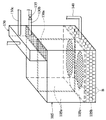
図1を参照すると、本実施例の温泉水生成システム100は、主に、溶解補助槽105、混合槽110、水源115、主溶解槽120、温泉水貯蔵タンク125、水圧調節装置130、第一流量制御弁135、第一輸送管140、液位感知素子145、第二輸送管150、ポンプ155、集気導管160、気体−液体混合器165、第一横輸送管170、第二流量制御弁175、第二横輸送管180、第三流量制御弁185、および第三輸送管190から構成される。
Referring to FIG. 1, the hot spring
図1で示されるように、水源115は出水管195により溶解補助槽105と混合槽110に連接されて、水道水を溶解補助槽105と混合槽110中に流入する。具体的には、水源115が提供する水道水は、水圧調節装置130を経て溶解補助槽105と混合槽110中に流入し、別に、直接、混合槽110中に流入する。
As shown in FIG. 1, the
図1と図2で示されるように、水圧調節装置130は溶解補助槽105と水源115の間に連接され、水圧調節装置130が溶解補助槽105上に設置され、溶解補助槽105中に流入された水道水の流量を調節する。さらに詳細には、水圧調節装置130は第一微流制御素子130a、第一出水管130b、および、第二出水管130cを有する。第一微流制御素子130aは溶解補助槽105の上部に連接されると共に、第一微流制御素子130aはフィルター膜、繊維フィルター布、あるいは、精密セラミック板から構成される。例えば、第一微流制御素子130aはセルギャップが1〜5μmのフィルター膜、あるいは、セルギャップが10μmの繊維フィルター布から構成される。第一出水管130bは第一微流制御素子130a上に位置し、第一出水管130bは混合槽110中に延伸する。第二出水管130cは第一出水管130bの上に位置すると共に、第二出水管130cは混合槽110中に延伸する。この他、第一流量制御弁135は、第一出水管130bの上に設置され、第一出水管130bを流れる水道水の流量を制御する。注意すべきことは、第一出水管130bを流れる水道水の流量は、好ましくは、第二出水管130cを流れる水道水の流量より少なく、その調整は第一流量制御弁135により行う。上述のように、第一微流制御素子130aの制限、および、第一出水管130bと第二出水管130cの存在により、水圧調節装置130中に流入する水道水は大部分が第一出水管130bと第二出水管130cから混合槽110中に流れ、極僅かな部分の水道水が第一微流制御素子130aから溶解補助槽105中に流入する。
As shown in FIGS. 1 and 2, the water
図1と図2を引き続き参照すると、溶解補助槽105は混合槽110に連接され、溶解補助槽105は二つの第一空間105aと第二空間105b、および、二つの第二微流制御素子105cを有する。第二微流制御素子105cは第一空間105aと第二空間105b間に設置され、第二微流制御素子105cも、フィルター膜、繊維フィルター布、あるいは、精密セラミック板から構成される。例えば、第二微流制御素子105cはセルギャップが1〜5μmのフィルター膜、あるいは、セルギャップが1μmの繊維フィルター布から構成される。二つの第一空間105aは第二空間105b上に位置し、それぞれ、二種の異なる溶解補助物質S、あるいは、相同の溶解補助物質Sをそれぞれ収納する(図1で示される)。例えば、二個の第一空間105aはそれぞれ、酸性、および、アルカリ性の溶解補助物質Sを収納する。第二空間105bは混合槽110に連通すると共に、第二空間105b内は複数の多孔バイオボール(あるいは、多孔ギャップボール)Bを収納する。さらに具体的には、第一輸送管140は第二空間105bと混合槽110の間に連接され、第二空間105bは第一輸送管140により混合槽110に連通する。この他、混合槽110内は複数の多孔バイオボール(あるいは、多孔ギャップボール)Bを収納する。
With continuing reference to FIGS. 1 and 2, the dissolution
主溶解補助槽120は混合槽110に連接される。さらに詳細には、第二輸送管150は混合槽110と主溶解槽120に連接され、ポンプ155は第二輸送管150に連接される。上述のように、主溶解槽120は第二輸送管150により混合槽110に連接される。この他、主溶解槽120内は多種の異なる温泉鉱物を収納する。さらに詳細には、図1で示されるように、主溶解補助槽120内は、選択的に三つの領域に区分され、三種の異なる温泉鉱物M1、M2、M3を収納する。例えば、温泉鉱物M1、M2、M3は、以下の物に限定されないが、それぞれ、麦飯石、電気石、および、活性炭で、温泉鉱物M1、M2、M3は、実際の泉質により異なる鉱物の種類と相関関係を有する。
The main dissolution
温泉水貯蔵タンク125は主溶解補助槽120に連接され、温泉水を保存する。さらに詳細には、第三輸送管190は主溶解補助槽120と貯蔵タンク125の間に連接される。よって、貯蔵タンク125は第三輸送管190により主溶解槽120に連接される。
The hot spring
液位感知素子145は貯蔵タンク125中に設置されると共に、水源115に電気的に連接され、ここで、液位感知素子145は主に、貯蔵タンク125中の温泉水の水位を感知し、感知信号を水源115に伝送して、水源115の給水を制御する。つまり、液位感知素子145は貯蔵タンク125中の温泉水の水位を感知し、水源115が継続して溶解補助槽105、および、混合槽110中に水道水を流入するかどうか決定する。
The liquid
集気導管160は、主溶解槽120、および、第二輸送管150に連通し、集気導管160は混合槽110中に延伸する。本実施例中、集気導管160はそれぞれ、主溶解槽120の三領域にそれぞれ連通する。
The
気体−液体混合器165は集気導管160と第二輸送管150の間に連接される。
The gas-
第一横輸送管170は第二輸送管150と混合槽110の間に連接され、第二流量制御弁175は第一横輸送管170上に設置される。
The first
第二横輸送管180は第二輸送管150と貯蔵タンク125の間に連接され、第三流量制御弁185は第二横輸送管180上に設置される。
The second
続いて、温泉水生成システム100の作動方式を説明する。
Next, the operation method of the hot spring
図1を参照すると、まず、水源115により提供される水道水は直接混合槽110に流入し、また、水圧調節装置130により溶解補助槽105中に流入する。注意すべきことは、水道水が水圧調節装置130に流入する時、第一微流制御素子130aの制限と第一出水管130bと第二出水管130cの存在により、水圧調節装置130中の水道水の大部分は、第一出水管130bと第二出水管130cから混合槽110中に流入し、極僅かな部分の水道水が第一微流制御素子130a(セルギャップが10μmの繊維フィルター布)から溶解補助槽105中に流入する。続いて、溶解補助槽105中に流入する少量の水道水は二個の第一空間105a内の溶解補助物質Sを流れ、溶解補助物質Sを溶解して、溶解補助剤を形成する。ここで、両第一空間105a内は、選択的に、酸性、および、アルカリ性の溶解補助物質Sを収納し、酸性アルカリ性の作用により、溶解補助剤のpHを調整する。例えば、両第一空間105a内が、すべて酸性の溶解補助物質Sである時、酸性の溶解補助剤を形成する。その後、溶解補助剤は第二微流制御素子105c(セルギャップが1μmの繊維フィルター布)を経て、第二空間105b中に流入し、第二空間105b内の複数の多孔バイオボール(あるいは、多孔セルギャップボール)B、および、第一輸送管140を経て、混合槽110中に流入する。注意すべきことは、第二微流制御素子105c(セルギャップが1μmの繊維フィルター布)を経て第二空間105bに流入する飽和溶解補助剤は複数の多孔バイオボール(あるいは、多孔セルギャップボール)Bで水と混合して(溶解補助剤の進行径路と混合時間が増長するため)、均一な溶解補助剤を形成する。
Referring to FIG. 1, first, tap water provided by the
この他、本実施例中、溶解補助槽105と第一輸送管140間の液圧が平衡を保持しなければならないので、混合槽110中に流入する溶解補助剤の量は、水圧調節装置130の第一微流制御素子130a(セルギャップが10μmのフィルター布)を経て溶解補助槽105中に流入する水道水の量と相同である。さらに詳細には、水源115が水道水を水圧調節装置130中に輸送するのを停止する時(あるいは、温泉水生成システム100が作動しない時)、溶解補助槽105はいかなる溶解補助剤も混合槽110中に流入させない。
In addition, in this embodiment, since the hydraulic pressure between the dissolution
溶解補助剤が混合槽110中に流入した後、溶解補助剤と混合槽110中の水道水が混合されて溶解補助液を形成する。ここで、混合槽110内の複数の多孔バイオボール(あるいは、多孔セルギャップボール)Bの配置により、溶解補助剤は混合槽110中の水道水と混合されて、均一な溶解補助液を形成する。続いて、溶解補助液はポンプ155の汲み取りにより、第二輸送管150から主溶解補助槽120中に流入する。ここで、溶解補助液は下から上に主溶解槽120内の温泉鉱物M1、M2、M3を流れ、反応して温泉水を形成する。つまり、溶解補助液は温泉鉱物M1、M2、M3に適当な濃度のイオン(カルシウムイオン、炭酸水素イオン、あるいは、水素イオン等)を溶出させる。例えば、溶解補助液は温泉鉱物M1(麦飯石)、M2(電気石)のイオン化と電解化を促し、温泉鉱物M3(活性炭)の吸着作用によりPH5〜6で、酸化還元電位が250mVの優良な温泉水を形成する。その後、主溶解槽125中の温泉水は、第三輸送管190を経て貯蔵タンク125中に流れる。最後に、貯蔵タンク125中の温泉水は出力管196により出力されて使用される。
After the solubilizer flows into the
一方、溶解補助液は主溶解槽120の三領域内の温泉鉱物M1、M2、M3と溶解反応する時、通常、溶解補助気体(例えば、二酸化炭素気体)を生成し、この種の溶解補助気体は温泉鉱物M1、M2、M3の溶解効率を向上させる。よって、三領域に連通する集気導管160は、溶解補助気体を収集する。特に、第二輸送管150が溶解補助液を輸送する時に提供される負圧、あるいは、吸力により、集気導管160内の溶解補助気体は気体−液体混合器165に吸い込まれて、第二輸送管150内の溶解補助液と気体−液体混合を実行する。気体−液体混合後の溶解補助気体と溶解補助液は一緒に主溶解槽120中に輸送され、温泉鉱物M1、M2、M3を経て、反応を促進して温泉水を形成する。
On the other hand, when the dissolution auxiliary liquid dissolves and reacts with the hot spring minerals M1, M2, and M3 in the three regions of the
この他、第二輸送管150により主溶解槽120に輸送される溶解補助液の流量が過大になるのを防止するため、第一横輸送管170上の第二流量制御弁175が開放されて、第二輸送管150中の溶解補助液を第一横輸送管170から混合槽110中に分流させ、これにより、主溶解槽120に流れる溶解補助液の流量は調節される。
In addition, the second flow
また、貯蔵タンク125中の温泉水が濃い場合(温泉水中のイオン含量が高い場合)、第二横輸送管180上の第三流量制御弁185は開放され、貯蔵タンク125中の温泉水は第二横輸送管180、および、第二輸送管150を経て主溶解槽120中に輸送され、再度、温泉鉱物M1、M2、M3と溶解反応する。最後に、再度、温泉鉱物M1、M2、M3と溶解反応した温泉水は、第三輸送管190を経て、貯蔵タンク125中に流入する。
When the hot spring water in the
上述のように、本発明の温泉水生成システムは効果的に温泉鉱物の溶解速度を増加し、短時間内で、水道水を泉質基準に符合する温泉水に転化させる。 As described above, the hot spring water generation system of the present invention effectively increases the dissolution rate of hot spring minerals, and converts tap water into hot spring water that meets spring quality standards within a short time.
本発明では好ましい実施の形態を前述の通り開示したが、本発明は決してこれらに限定されるものではなく、当業者であれば、本発明の精神と範囲を脱しない範囲内で各種の変形や修正を加えることができるが、これらが特許請求の範囲に含まれることはいうまでもない。 The preferred embodiments of the present invention have been disclosed as described above. However, the present invention is not limited to these embodiments, and those skilled in the art will recognize various modifications and changes within the spirit and scope of the present invention. Modifications can be made, but it goes without saying that these are within the scope of the claims.
100 温泉水生成システム
105 溶解補助槽
105a 第一空間
105b 第二空間
105c 第二微流制御素子
110 混合槽
115 水源
120 主溶解槽
125 温泉水貯蔵タンク
130 水圧調節裝置
130a 第一微流制御素子
130b 第一出水管
130c 第二出水管
135 第一流量制御弁
140 第一輸送管
145 液位感知素子
150 第二輸送管
155 ポンプ
160 集気導管
165 気体−液体混合器
170 第一横通輸送管
175 第二流量制御弁
180 第二横通輸送管
185 第三流量制御弁
190 第三輸送管
195 出水管
196 出力管
B 多孔バイオボール
M1、M2、M3 温泉鉱物
S 溶解補助物質
100 Hot Spring
Claims (20)
少なくとも一つの溶解補助物質を収容する溶解補助槽と、
前記溶解補助槽に連接される混合槽と、
前記溶解補助槽と前記混合槽に連接され、水道水を前記溶解補助槽と前記混合槽中に流入して溶解補助剤を形成し、前記溶解補助剤は前記混合槽中に流入して、前記混合槽中の水道水と混合されて溶解補助液を形成する水源と、
前記混合槽に連接されると共に、少なくとも一つの温泉鉱物を収容し、前記混合槽の前記溶解補助液が流入し、前記温泉鉱物と反応して温泉水を形成する主溶解槽と、
前記主溶解槽に連接されて、温泉水を保存する貯蔵タンクと
からなることを特徴とする温泉水生成システム。 A hot spring water generation system,
A solubilization tank containing at least one solubilizing substance; and
A mixing tank connected to the dissolution auxiliary tank;
It is connected to the dissolution auxiliary tank and the mixing tank, tap water is introduced into the dissolution auxiliary tank and the mixing tank to form a dissolution auxiliary agent, the dissolution auxiliary agent flows into the mixing tank, A water source mixed with tap water in a mixing tank to form a solubilizing solution;
A main dissolution tank that is connected to the mixing tank and contains at least one hot spring mineral, the dissolution auxiliary liquid of the mixing tank flows in, and reacts with the hot spring mineral to form hot spring water;
A hot spring water generation system comprising a storage tank connected to the main dissolution tank and storing hot spring water.
Applications Claiming Priority (1)
| Application Number | Priority Date | Filing Date | Title |
|---|---|---|---|
| TW95150115A TW200827309A (en) | 2006-12-29 | 2006-12-29 | Hot spring water generating system |
Publications (1)
| Publication Number | Publication Date |
|---|---|
| JP2008161663A true JP2008161663A (en) | 2008-07-17 |
Family
ID=39691882
Family Applications (1)
| Application Number | Title | Priority Date | Filing Date |
|---|---|---|---|
| JP2007130564A Pending JP2008161663A (en) | 2006-12-29 | 2007-05-16 | Hot spring water generation system |
Country Status (2)
| Country | Link |
|---|---|
| JP (1) | JP2008161663A (en) |
| TW (1) | TW200827309A (en) |
Cited By (2)
| Publication number | Priority date | Publication date | Assignee | Title |
|---|---|---|---|---|
| JP5187867B1 (en) * | 2012-05-21 | 2013-04-24 | 満尚 壱岐 | Heat exchange tank and heat exchange system using steam |
| KR101847573B1 (en) * | 2016-05-06 | 2018-04-10 | 정수룡 | Apparatus for producing health-water |
Families Citing this family (1)
| Publication number | Priority date | Publication date | Assignee | Title |
|---|---|---|---|---|
| CN102101702B (en) * | 2009-12-21 | 2013-01-23 | 泓发乐活氏水科技服务股份有限公司 | Hot spring generating machine |
Citations (3)
| Publication number | Priority date | Publication date | Assignee | Title |
|---|---|---|---|---|
| JPS5244237U (en) * | 1975-09-25 | 1977-03-29 | ||
| JP2001037844A (en) * | 1999-08-03 | 2001-02-13 | Ando Takamori | Water extraction device for artificial warm bath |
| JP2001213968A (en) * | 2000-02-02 | 2001-08-07 | Kurita Water Ind Ltd | Method for dissolving water-soluble polymer and dissolution apparatus therefor |
-
2006
- 2006-12-29 TW TW95150115A patent/TW200827309A/en unknown
-
2007
- 2007-05-16 JP JP2007130564A patent/JP2008161663A/en active Pending
Patent Citations (3)
| Publication number | Priority date | Publication date | Assignee | Title |
|---|---|---|---|---|
| JPS5244237U (en) * | 1975-09-25 | 1977-03-29 | ||
| JP2001037844A (en) * | 1999-08-03 | 2001-02-13 | Ando Takamori | Water extraction device for artificial warm bath |
| JP2001213968A (en) * | 2000-02-02 | 2001-08-07 | Kurita Water Ind Ltd | Method for dissolving water-soluble polymer and dissolution apparatus therefor |
Cited By (2)
| Publication number | Priority date | Publication date | Assignee | Title |
|---|---|---|---|---|
| JP5187867B1 (en) * | 2012-05-21 | 2013-04-24 | 満尚 壱岐 | Heat exchange tank and heat exchange system using steam |
| KR101847573B1 (en) * | 2016-05-06 | 2018-04-10 | 정수룡 | Apparatus for producing health-water |
Also Published As
| Publication number | Publication date |
|---|---|
| TW200827309A (en) | 2008-07-01 |
Similar Documents
| Publication | Publication Date | Title |
|---|---|---|
| KR101370129B1 (en) | Hydrogen abundant water making apparatus with function to adjust dissolved hydrogen | |
| US12017936B2 (en) | Mineralization cartridge and method for the operation thereof | |
| KR20160062674A (en) | Hydrogen water purifier having hydrogen water creating module | |
| JP2009248048A (en) | Gas/liquid-mixed water generating apparatus | |
| CN103523966A (en) | Advanced wastewater treatment system and treatment method | |
| CN117065592A (en) | Preparation device and preparation method of supersaturated hydrogen solution | |
| JP2010088972A (en) | Hydrogen-containing electrolytic water generation device and hot water supply device | |
| JP2008161663A (en) | Hot spring water generation system | |
| JP2017501016A (en) | Saltwater mining process | |
| JP5332196B2 (en) | Microbial power generation method and microbial power generation apparatus | |
| JP2007134247A (en) | Fuel cell device | |
| CN111094193A (en) | Water treatment device and water treatment system | |
| JP2007301541A (en) | Slightly acidic electrolyzed water generation method and apparatus | |
| US7314568B2 (en) | Water conditioning system | |
| JP2006314985A (en) | Device for purifying wastewater in wastewater tank | |
| JP2001104941A (en) | Gas-liquid separator | |
| JP4200118B2 (en) | Alkaline ion water conditioner | |
| CN106904721B (en) | Seawater desalination and mineralization integrated system and use method thereof | |
| JP2007258026A (en) | Water treatment system of fuel cell device | |
| JP2007160171A (en) | System for supplying drinking water and/or functional water | |
| JP2001191079A (en) | Electrolytic water forming device | |
| JPH06285482A (en) | Gas-liquid contact device and gas-liquid contact system | |
| Pasveer et al. | A new development in diffused air aeration | |
| JP2019033057A (en) | Microbial fuel cell | |
| US10792622B2 (en) | Gas dissolving system with two mixers |
Legal Events
| Date | Code | Title | Description |
|---|---|---|---|
| A131 | Notification of reasons for refusal |
Effective date: 20100420 Free format text: JAPANESE INTERMEDIATE CODE: A131 |
|
| RD03 | Notification of appointment of power of attorney |
Free format text: JAPANESE INTERMEDIATE CODE: A7423 Effective date: 20100602 |
|
| A02 | Decision of refusal |
Free format text: JAPANESE INTERMEDIATE CODE: A02 Effective date: 20100921 |