JP2008160271A - Wireless communication apparatus and wireless communication method - Google Patents
Wireless communication apparatus and wireless communication method Download PDFInfo
- Publication number
- JP2008160271A JP2008160271A JP2006344303A JP2006344303A JP2008160271A JP 2008160271 A JP2008160271 A JP 2008160271A JP 2006344303 A JP2006344303 A JP 2006344303A JP 2006344303 A JP2006344303 A JP 2006344303A JP 2008160271 A JP2008160271 A JP 2008160271A
- Authority
- JP
- Japan
- Prior art keywords
- information
- relay
- wireless communication
- packet
- time
- Prior art date
- Legal status (The legal status is an assumption and is not a legal conclusion. Google has not performed a legal analysis and makes no representation as to the accuracy of the status listed.)
- Granted
Links
Images


Landscapes
- Small-Scale Networks (AREA)
- Mobile Radio Communication Systems (AREA)
Abstract
【課題】効率的な同報通信を実現することができる無線通信装置及び方法を得る。
【解決手段】同報通信の場合、自身のID、ネイバーリスト5に登録されたID情報、及び同報情報を含むパケットを生成して他の端末へ送信する送信パケット生成部2と、受信したパケットから送信者ID、中継リスト及び送信情報を分離する受信パケット分離部4と、分離された送信者ID及び中継リストを合成し、この合成したID情報とネイバーリスト5のID情報を比較して両者共通情報を抽出し、ネイバーリスト5のID情報から両者共通情報を削除してID情報が残っている場合には、送信者IDとして自身のID、中継リストとしてネイバーリスト5に登録されたID情報から分離された送信者IDを除いたID情報、及び送信情報として分離された同報情報を含むパケットを生成し、送信パケット生成部2を経由して他の端末へ送信する中継管理部6を設けた。
【選択図】図1A wireless communication apparatus and method capable of realizing efficient broadcast communication are provided.
In the case of broadcast communication, a transmission packet generator 2 that generates a packet including its own ID, ID information registered in a neighbor list 5, and broadcast information and transmits the packet to another terminal is received. The received packet separation unit 4 that separates the sender ID, the relay list, and the transmission information from the packet and the separated sender ID and the relay list are combined, and the combined ID information and the ID information of the neighbor list 5 are compared. If the common information is extracted and the common information is deleted from the ID information of the neighbor list 5 and the ID information remains, the own ID as the sender ID and the ID registered in the neighbor list 5 as the relay list A packet including ID information excluding the sender ID separated from the information and broadcast information separated as transmission information is generated, and other packets are transmitted via the transmission packet generation unit 2 Provided relay management unit 6 to be transmitted to the end.
[Selection] Figure 1
Description
この発明は、無線によるマルチホップデータ通信を行う無線通信ネットワークシステムにおいて、周辺端末情報に基づいて中継中止や、遅延時間の付加を行うことで、通信パケットの衝突を防止し、かつ通信数の削減を図った無線通信装置及び無線通信方法に関するものである。 In a wireless communication network system that performs multihop data communication by wireless, the present invention prevents collision of communication packets and reduces the number of communication by stopping relaying and adding delay time based on peripheral terminal information The present invention relates to a wireless communication apparatus and a wireless communication method.
無線通信ネットワークシステムで同じデータを全端末に伝達する同報通信を実現する場合、一般的には宛先を固定しないブロードキャスト通信を用いる。マルチホップ環境の場合、受信した端末が中継者となりブロードキャストを繰返すことで全端末へ行き渡らせる方法をとる。しかし、端末密度が高い場合、一時期に多くの通信が狭い空間内で発生し、トラヒックの急増、干渉による通信品質の低下を招く。 In order to realize broadcast communication in which the same data is transmitted to all terminals in a wireless communication network system, broadcast communication in which a destination is not fixed is generally used. In the case of a multi-hop environment, a method is adopted in which the received terminal becomes a repeater and is distributed to all terminals by repeating broadcasts. However, when the terminal density is high, many communications are generated in a narrow space at one time, resulting in a rapid increase in traffic and a decrease in communication quality due to interference.
これを防ぐためには、あらかじめ各端末への中継経路を決定し、個別通信で情報を伝達する方法がある(例えば、特許文献1参照)。しかし、端末数が多くなると長い通信時間が必要となり、効率が悪い。 In order to prevent this, there is a method in which a relay route to each terminal is determined in advance and information is transmitted by individual communication (for example, see Patent Document 1). However, when the number of terminals increases, a long communication time is required and the efficiency is poor.
上述したような従来の同報通信では、端末数が多くなると長い通信時間が必要となり、効率が悪いという問題点があった。効率的な同報通信を実現するためには、同じ通信範囲では衝突を発生させず、異なる通信範囲では同時に通信を実施させることが好ましい。 In the conventional broadcast communication as described above, when the number of terminals increases, a long communication time is required, and there is a problem that the efficiency is low. In order to realize efficient broadcast communication, it is preferable that no collision occurs in the same communication range and communication is performed simultaneously in different communication ranges.
この発明は、上述のような課題を解決するためになされたもので、その目的は、マルチホップデータ通信で中継経路を決定するために利用される、通信範囲に存在する通信端末のID情報(ネイバーリスト)を中継者の選択と送信時間調整に利用することで、効率的な同報通信を実現することができる無線通信装置及び無線通信方法を得るものである。 The present invention has been made to solve the above-described problems, and its purpose is to use ID information (in the communication range, which is used to determine a relay route in multi-hop data communication) ( By using a neighbor list for relay selection and transmission time adjustment, a wireless communication device and a wireless communication method capable of realizing efficient broadcast communication are obtained.
この発明に係る無線通信装置は、無線によるマルチホップデータ通信を行う無線通信ネットワークシステムにおいて、電源が投入されると、自身のIDのみを送信パケットとして送信する送信パケット生成部と、受信したパケットから送信者IDを分離してネイバーリストに登録する受信パケット分離部とが設けられ、自身の通信範囲に存在する他の全ての無線通信装置のID情報を前記ネイバーリストに登録した無線通信装置であって、同報通信の場合、前記送信パケット生成部は、送信者IDとして自身のID、中継リストとして前記ネイバーリストに登録されたID情報、及び送信情報として同報情報を含むパケットを生成して他の無線通信装置へ送信し、前記受信パケット分離部は、受信したパケットから送信者ID、中継リスト及び送信情報を分離し、前記受信パケット分離部により分離された送信者ID及び中継リストを合成し、この合成したID情報と前記ネイバーリストのID情報を比較して両者共通情報を抽出し、前記ネイバーリストのID情報から前記両者共通情報を削除してID情報が残っている場合には、送信者IDとして自身のID、中継リストとして前記ネイバーリストに登録されたID情報から分離された送信者IDを除いたID情報、及び送信情報として分離された同報情報を含むパケットを生成し、前記送信パケット生成部を経由して他の無線通信装置へ送信する中継管理部をさらに設けたものである。 In a wireless communication network system that performs wireless multi-hop data communication, a wireless communication device according to the present invention includes a transmission packet generation unit that transmits only its own ID as a transmission packet when power is turned on, and a received packet A reception packet separation unit that separates a sender ID and registers it in a neighbor list, and is a wireless communication device that registers ID information of all other wireless communication devices existing in its communication range in the neighbor list. In the case of broadcast communication, the transmission packet generator generates a packet including its own ID as a sender ID, ID information registered in the neighbor list as a relay list, and broadcast information as transmission information. Transmitted to another wireless communication device, and the received packet separation unit transmits a sender ID, a relay list and a received packet from the received packet. The transmission information is separated, the sender ID and the relay list separated by the received packet separation unit are combined, the combined ID information is compared with the ID information of the neighbor list, and both common information is extracted, and the neighbor If the common information is deleted from the ID information of the list and the ID information remains, the sender ID as the sender ID and the sender ID separated from the ID information registered in the neighbor list as the relay list A relay management unit is further provided that generates a packet including the ID information excluding ID and the broadcast information separated as transmission information and transmits the packet to another wireless communication device via the transmission packet generation unit. .
この発明に係る無線通信装置は、マルチホップデータ通信で中継経路を決定するために利用される、通信範囲に存在する通信端末のID情報(ネイバーリスト)を中継者の選択と送信時間調整に利用することで、効率的な同報通信を実現することができるという効果を奏する。 The wireless communication apparatus according to the present invention uses ID information (neighbor list) of communication terminals existing in a communication range, which is used to determine a relay route in multi-hop data communication, for selection of a relay person and transmission time adjustment. By doing so, there is an effect that efficient broadcast communication can be realized.
実施の形態1.
この発明の実施の形態1に係る無線通信装置について図1から図7までを参照しながら説明する。図1は、この発明の実施の形態1に係る無線通信装置の構成を示す図である。なお、以降では、各図中、同一符号は同一又は相当部分を示す。
Embodiment 1 FIG.
A wireless communication apparatus according to Embodiment 1 of the present invention will be described with reference to FIGS. 1 is a diagram showing a configuration of a wireless communication apparatus according to Embodiment 1 of the present invention. In the following, in each figure, the same reference numerals indicate the same or corresponding parts.
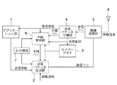
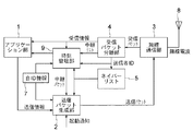
図1において、この実施の形態1に係る無線通信装置は、時刻情報、センサ情報、制御情報など、本無線通信ネットワークシステムを利用し送信すべきデータを生成あるいは受信したデータを用いて制御を実現するためのアプリケーション部1と、無線通信要求の情報に、通信管理情報を付加し無線通信パケットとして形成する送信パケット生成部2と、送信パケットを無線電波として送信、および無線電波を受信し受信パケットとして出力する無線通信部3と、無線通信部3が受信したパケットから送信者ID、中継リスト、受信情報を分離する受信パケット分離部4と、受信パケットの送信者IDを登録するネイバーリスト5と、同報(ブロードキャスト)パケットに対し中継の有無および中継時間を管理する中継管理部6と、自身のID情報7と、アンテナ8とが設けられている。なお、アプリケーション部1、送信パケット生成部2、無線通信部3、受信パケット分離部4、中継管理部6などは、例えば、マイコン上のソフトウェアで実現している。
In FIG. 1, the wireless communication apparatus according to the first embodiment implements control using data generated or received using the wireless communication network system, such as time information, sensor information, and control information. An application unit 1 for transmission, a transmission
図2は、この発明の実施の形態1に係る無線通信装置の送信パケット生成部の構成を示す図である。 FIG. 2 is a diagram showing a configuration of a transmission packet generation unit of the wireless communication apparatus according to Embodiment 1 of the present invention.
図2において、この実施の形態1に係る無線通信装置の送信パケット生成部2は、中継管理部6からの中継要求、及びアプリケーション部1からの送信要求によってリセットし、中継要求及び送信要求がない間の時間をカウントするタイマ21と、このタイマ21のタイムアウト及び起動通知を検知した場合には自IDを、中継要求及び送信要求を検知した場合には送信パケットを出力する出力制御部22とが設けられている。
In FIG. 2, the transmission
つぎに、この実施の形態1に係る無線通信装置の動作について図面を参照しながら説明する。図3は、この発明の実施の形態1に係る無線通信装置の通信パケットのフォーマットを示す図である。 Next, the operation of the wireless communication apparatus according to the first embodiment will be described with reference to the drawings. FIG. 3 is a diagram showing a communication packet format of the wireless communication apparatus according to Embodiment 1 of the present invention.
図3において、動作説明に必要な「送信者ID」、「中継リスト」、「送/受信情報」の3種類のフィールドについて定義しているが、実際の運用においてはさらに多くの情報フィールドを備えてもよい。 In FIG. 3, three types of fields “sender ID”, “relay list”, and “transmission / reception information” necessary for operation description are defined. However, in actual operation, more information fields are provided. May be.
端末(無線通信装置)の電源が投入されると、起動通知がセットされ、送信パケット生成部2の出力制御部22は、自身のIDのみを送信パケットとして送出する。この送信パケットは、無線通信部3によって無線送出され、既に電源の投入されている無線伝達範囲に存在する端末に伝達される。
When the terminal (wireless communication apparatus) is powered on, an activation notification is set, and the
受信した各端末内では、無線通信部3より受信パケット分離部4に送られ、ここで受信したIDが分離される。中継リスト及び受信情報フィールドは存在しないため、アプリケーション部1や中継管理部6へは伝えられない。分離したIDは、ネイバーリスト5に登録される。
Within each received terminal, the
また、送信パケット生成部2のタイマ21により、一定期間自身からの送信を実行していない場合、自身のIDの送信を再実行することで、後から電源投入された端末のネイバーリスト5へIDを登録させる。
In addition, when transmission from the
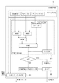
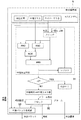
図4は、この発明の実施の形態1に係る無線通信装置が3台の場合のネイバーリスト登録動作を示す図である。 FIG. 4 is a diagram showing a neighbor list registration operation when there are three wireless communication apparatuses according to Embodiment 1 of the present invention.
ステップ101〜102において、端末(無線通信装置)Aの電源が投入されると、起動通知がセットされ、送信パケット生成部2の出力制御部22は、自身のIDのみを送信パケットとして送出する。この送信パケットは、無線通信部3によって無線送出される。
In
ステップ103〜104において、端末(無線通信装置)Bからパケットを受信した端末A内では、無線通信部3より受信パケット分離部4に送られ、ここで受信したIDが分離される。中継リスト及び受信情報フィールドは存在しないため、アプリケーション部1や中継管理部6へは伝えられない。分離したIDは、ネイバーリスト5に登録される。
In
ステップ105〜106において、端末(無線通信装置)Cからパケットを受信した端末A内の動作は、ステップ103〜104と同様である。
In
ステップ107において、送信パケット生成部2のタイマ21により、一定期間自身からの送信を実行していない場合、自身のIDの送信を再実行することで、後から電源投入された端末B、Cのネイバーリスト5へIDを登録させる。
In
端末Bのステップ201〜207の動作や、端末Cのステップ301〜306の動作は、上述した端末Aのステップ101〜107の動作と同様である。
The operations of
なお、一般的なアドホック通信をサポートしている端末では、本動作を省略してもよい。アドホック通信におけるルート構築過程における無線送受信によって、ネイバーリスト5へのID登録が実現される。
Note that this operation may be omitted in a terminal that supports general ad hoc communication. ID registration to the
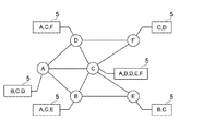
図5は、この発明の実施の形態1に係る無線通信装置が6台の場合のネイバーリスト登録状況を示す図である。 FIG. 5 is a diagram showing a neighbor list registration situation when there are six wireless communication apparatuses according to the first embodiment of the present invention.
図5に示すように、例えば、端末(無線通信装置)Aから端末(無線通信装置)Fまでの6台が配置され、実線範囲が通信可能であるとすると、上記のネイバーリスト登録動作により、端末Aのネイバーリスト5はB、C、D、端末Bのネイバーリスト5はA、C、E、端末Cのネイバーリスト5はA、B、D、E、F、端末Dのネイバーリスト5はA、C、F、端末Eのネイバーリスト5はB、C、端末Fのネイバーリスト5はC、Dとなる。
As shown in FIG. 5, for example, if six units from a terminal (wireless communication device) A to a terminal (wireless communication device) F are arranged and the solid line range is communicable, the above neighbor list registration operation The
各端末A〜Fのネイバーリスト5に上記ID情報が登録されている状態で、端末Aのアプリケーション部1が全端末に対し同報通信を要求した時、端末Aの送信パケット生成部2は、アプリケーション部1の送信情報に、ネイバーリスト5に登録されている端末B、C、DのID情報を中継リストフィールドとして付加する。ここでは、この順番で付加することとする。さらに、自ID情報を送信者IDフィールドに付加することで送信パケットを生成し、これを無線通信部3へ送り無線送出する。この送信パケットは、端末B、C、Dで受信される。
In a state where the ID information is registered in the
ここで、端末Bの受信パケット分離部4は、中継管理部6へ中継リストとして端末B、C、DのID情報と、送信者IDとして端末AのID情報を伝える。
Here, the received packet separation unit 4 of the terminal B transmits the ID information of the terminals B, C, and D as a relay list to the
図6は、この発明の実施の形態1に係る無線通信装置の中継管理部の構成を示す図である。 FIG. 6 is a diagram showing the configuration of the relay management unit of the wireless communication apparatus according to Embodiment 1 of the present invention.
図6において、中継管理部6は、送信者ID、受信中継リスト及びネイバーリスト5を比較し中継実施を判断する中継判定回路61と、中継時間を管理するタイマ62と、自身が中継する時の中継リストを生成し情報フィールドと合成して中継パケットを生成する中継パケット生成部63とが設けられている。なお、図6中の中継時刻+=中継リスト数は、中継時刻=中継時刻+中継リスト数を表す(図9も同様)。
In FIG. 6, the
端末Bの中継判定回路61の動作は、次のようになる。受信した中継リストと送信者IDを合成し、端末A、B、C、DのID情報とする。これと自身のネイバーリスト5の端末A、C、EのID情報を比較する。両者共通情報は端末A、CのID情報である。そこで自身のネイバーリスト5の情報から端末A、CのID情報を削除すると、ネイバーリスト5には端末EのID情報が残る。情報が残らない場合は、ここで中継動作は中止となる。また、中継送信する前に、他の端末が送信する同じ同報情報をもつパケットを受信した時には、受信パケット分離部4により分離された送信者ID及び中継リストを合成し、この合成したID情報とネイバーリスト5のID情報を比較して両者共通情報を抽出し、ネイバーリスト5のID情報から両者共通情報を削除してID情報が残っていない場合には、中継動作を中止する。情報が残っているので、端末EのID情報をレジスタに記憶し、タイマ62に遅延値(遅延時間)を設定する。このタイマ62の遅延値は、受信した中継リスト中に、自身のIDが何番目(序数)にあるかで決定する。端末BのID情報は1番目にあるため、1T(T=あらかじめ設定した時間単位)の時間を設定する。
The operation of the
同様にして、端末Cは、中継判定回路61のレジスタに端末E、FのID情報を残し、2Tの時間待ちを、端末Dは、同レジスタに端末FのID情報を残し、3Tの時間待ちを実行する。
Similarly, the terminal C leaves the ID information of the terminals E and F in the register of the
1Tの時間経過後、端末Bの中継管理部6は、中継パケットの送信を要求する。このとき、中継パケット生成部63は、ネイバーリスト5から送信者IDである端末AのID情報を除いた端末C、EのID情報を中継リストとして、受信情報と合成した中継パケットを送信パケット生成部2へ送り、無線通信部3を経由し無線送出する。
After 1T elapses, the
端末Bから送信した中継パケットは、端末A、C、Eによって受信される。端末Aは、既に送信を完了しているのでこれを破棄する。端末Cは、中継管理部6のタイマ62によって中継送信の待ち状態にある。この場合、端末Cの中継判定回路61は、送信者IDである端末BのID情報と、受信した中継リストに含まれる端末C、EのID情報を、レジスタに記憶している端末E、FのID情報と比較する。この結果、端末FのID情報が残る。ここで、タイマ62には中継リストの数=2Tが加算され、中継送信時刻が延長される。
The relay packet transmitted from terminal B is received by terminals A, C, and E. Since terminal A has already completed transmission, terminal A discards it. The terminal C is in a waiting state for relay transmission by the
一方、端末Eは、端末Bのパケットを受信し、送信者ID及び中継リストに含まれる端末B、C、EのID情報と、自身のネイバーリスト5に登録されている端末B、CのID情報が比較される。ネイバーリスト5内の情報がすべて一致するため、レジスタには情報が残らない。よって、端末Eの中継判定回路61は、中継中止と判断する。
On the other hand, the terminal E receives the packet of the terminal B, the sender ID and the ID information of the terminals B, C, and E included in the relay list, and the IDs of the terminals B and C registered in its
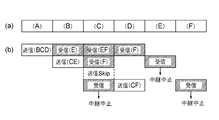
図7は、この発明の実施の形態1に係る無線通信装置が6台の場合のそれぞれの動作を示す図である。 FIG. 7 is a diagram showing each operation when there are six wireless communication apparatuses according to the first embodiment of the present invention.
図7において、(a)は6台の端末A〜Fを示す。また、(b)は、送信のカッコ内記載が送信中継リストに含まれる端末、受信(斜線)のカッコ内記載が中継判定回路61内のレジスタに残る端末を示す。端末C、E、Fは、他の中継パケットを受信することで中継中止となる。この例では、端末A、B、Dの3回のパケット送信で全端末に情報が伝達されている。一般的な同報通信の場合、全端末が1回送信することになるため、この例では6回となる。つまり、必要とされる通信数は半減している。
7A shows six terminals A to F. FIG. Further, (b) shows a terminal whose transmission parenthesis is included in the transmission relay list, and a reception (hatched) parenthesis that remains in the register in the
上記のようにネイバーリスト5を元に中継リストを生成し、これを同報通信情報とともに送出し、本中継リストを元にした規則に則り中継送信タイミングを遅らせ、その間に受信した同情報の中継パケットを受信し、自身のネイバーリスト5と比較し中継停止を制御することで、同報通信の通信数を削減できる効果がある。
As described above, a relay list is generated based on the
なお、中継管理部6は、中継送信する前に、他の端末が送信する同じ同報情報をもつパケットを受信した時には、受信の度に(序数−繰返し受信回数)に固定値を乗算した値を、タイマ62の遅延値に加算し送信を遅らせるだけでなく、タイマ62の遅延値にさらにランダム時間を加算してもよい。
When the
また、中継送信タイミングを隣接する端末間でずらしているため、通信衝突を防ぐことができ、衝突によるエラー率の増大及び衝突検知による再送が元でのトラヒック増大を抑止する効果もある。 Further, since the relay transmission timing is shifted between adjacent terminals, communication collision can be prevented, and an increase in error rate due to collision and an effect of suppressing increase in traffic due to retransmission due to collision detection can be obtained.
さらに、ネイバーリスト5の登録に必要な自ID送信は、一般的な情報通信やルート構築時の通信と兼用することができ、登録に必要なオーバヘッドが不要である特徴もある。
Further, the own ID transmission necessary for registration of the
実施の形態2.
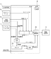
この発明の実施の形態2に係る無線通信装置について図8から図11までを参照しながら説明する。上記の実施の形態1は、一般的な同報通信について説明したが、この実施の形態2では、同報通信を用いて無線通信装置の時刻を同期する方式について説明する。図8は、この発明の実施の形態2に係る無線通信装置の構成を示す図である。また、図9は、この発明の実施の形態2に係る無線通信装置の時刻管理部の構成を示す図である。
A wireless communication apparatus according to
図8において、この実施の形態2に係る無線通信装置は、上記の実施の形態1と比較して、中継管理部6が時刻管理部9に置き換わっている点が相違する。なお、アプリケーション部1、送信パケット生成部2、無線通信部3、受信パケット分離部4、時刻管理部9などは、例えば、マイコン上のソフトウェアで実現している。
In FIG. 8, the wireless communication apparatus according to the second embodiment is different from the first embodiment in that the
図9において、この実施の形態2に係る無線通信装置の時刻管理部9は、上記の中継管理部6と比較して、中継送信時間を制御するタイマ62が時刻をカウントするクロック92に置き換わっている点が相違する。
In FIG. 9, the
つぎに、この実施の形態2に係る無線通信装置の動作について図面を参照しながら説明する。図10は、この発明の実施の形態2に係る無線通信装置の通信パケットのフォーマットを示す図である。
Next, the operation of the wireless communication apparatus according to the second embodiment will be described with reference to the drawings. FIG. 10 is a diagram showing the format of a communication packet of the wireless communication apparatus according to
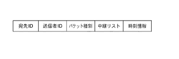
図10において、アプリケーション部1が通信する相手先を選択する通信と、時刻の伝達が混在するため、上記の実施の形態1の通信パケットの「送信者ID」、「中継リスト」、「送/受信情報」に、「宛先ID」と「パケット種別」が追加となる。時刻の伝達の場合、宛先IDとして同報通信を示すID番号が入り、送/受信情報として時刻情報が入る。アプリケーション部1が伝達するパケットの場合、中継リストはブランクか、別の情報が含まれる。 In FIG. 10, since the communication for selecting the other party with which the application unit 1 communicates and the transmission of the time are mixed, the “sender ID”, “relay list”, “send / send” of the communication packet of the first embodiment described above. “Destination ID” and “Packet type” are added to “Reception information”. In the case of time transmission, an ID number indicating broadcast communication is entered as the destination ID, and time information is entered as transmission / reception information. In the case of a packet transmitted by the application unit 1, the relay list is blank or includes other information.
なお、高精度な時刻同期を実現するために、時刻情報のほかに補正情報を加えても良い。ただし、補正情報の生成方法は、この発明の説明外である。 In order to realize highly accurate time synchronization, correction information may be added in addition to time information. However, the method for generating correction information is outside the description of the present invention.
図11は、この発明の実施の形態2に係る無線通信装置による時刻同期におけるシステム構成を示す図である。
FIG. 11 is a diagram showing a system configuration in time synchronization by the radio communication apparatus according to
複数の端末のなかの任意の1つが、基準時刻となり、これをタイムマスタTMと呼ぶ。残りの端末は、時刻を受信し、自身のクロックを補正するタイムスレーブTSである。 Any one of the plurality of terminals serves as a reference time, which is referred to as a time master TM. The remaining terminals are time slaves TS that receive time and correct their clocks.
タイムマスタTMは、クロック92に定期的にアラームを発生するように設定している。これは時刻同期を実施する周期であり、同報通信によって全端末が時刻を受信するために必要とされる時間に比べ、長い周期に設定される。タイムマスタTMのクロック92がアラームを発生すると、送信要求が送信パケット生成部2へ通知される。同時にアラーム設定時刻が時刻情報として、ネイバーリスト5が中継リストとして、さらに同報通信を示す宛先IDと時刻通信を示すパケット種別情報がパケットとして合成される。送信パケット生成部2は、時刻管理部9のパケットに自IDを追加し無線通信部3経由で無線送出する。
The time master TM is set to generate an alarm periodically on the
タイムマスタTMの時刻パケットを受信したタイムスレーブTSは、受信情報に含まれる時刻情報を自身のクロックに設定する。さらに、上記の実施の形態1で説明した中継判定回路91の動作に従い、中継判断と中継時間の設定を実施する。中継時間の設定では、クロック92へのアラーム時刻として設定される。
The time slave TS that has received the time packet of the time master TM sets the time information included in the reception information to its own clock. Further, according to the operation of the
タイムスレーブTSのクロック92がアラームを発生すると、タイムマスタTMと同様に送信要求とパケット合成が実施される。中継リストは、上記の実施の形態1で説明した方法と同様、受信パケットの送信者IDを除くネイバーリスト5のID情報となる。また、時刻の中継では、受信情報を中継せず、クロック92のアラーム時刻を新たな時刻情報としている。これにより、中継の遅延によらず最新の時刻が伝達されるため、中継段数が多い場合でも端末間の誤差が少ない時刻の同期が実現できる。
When the
以上のように端末への時刻伝達に、ここで説明した同報通信を用いることで、わずかなトラヒックで時刻を伝達できるので、アプリケーションの通信を妨害することなく、端末の時刻を同期することができる。 As described above, by using the broadcast communication described here for the time transmission to the terminal, the time can be transmitted with a little traffic, so that the time of the terminal can be synchronized without interfering with the communication of the application. it can.
1 アプリケーション部、2 送信パケット生成部、3 無線通信部、4 受信パケット分離部、5 ネイバーリスト、6 中継管理部、8 アンテナ、9 時刻管理部、21 タイマ、22 出力制御部、61 中継判定回路、62 タイマ、63 中継パケット生成部、91 中継判定回路、92 クロック。
DESCRIPTION OF SYMBOLS 1 Application part, 2 Transmission packet generation part, 3 Wireless communication part, 4 Reception packet separation part, 5 Neighbor list, 6 Relay management part, 8 Antenna, 9 Time management part, 21 Timer, 22 Output control part, 61
Claims (18)
電源が投入されると、自身のIDのみを送信パケットとして送信する送信パケット生成部と、
受信したパケットから送信者IDを分離してネイバーリストに登録する受信パケット分離部とを備え、
自身の通信範囲に存在する他の全ての無線通信装置のID情報を前記ネイバーリストに登録した無線通信装置であって、
同報通信の場合、前記送信パケット生成部は、送信者IDとして自身のID、中継リストとして前記ネイバーリストに登録されたID情報、及び送信情報として同報情報を含むパケットを生成して他の無線通信装置へ送信し、
前記受信パケット分離部は、受信したパケットから送信者ID、中継リスト及び送信情報を分離し、
前記受信パケット分離部により分離された送信者ID及び中継リストを合成し、この合成したID情報と前記ネイバーリストのID情報を比較して両者共通情報を抽出し、前記ネイバーリストのID情報から前記両者共通情報を削除してID情報が残っている場合には、送信者IDとして自身のID、中継リストとして前記ネイバーリストに登録されたID情報から分離された送信者IDを除いたID情報、及び送信情報として分離された同報情報を含むパケットを生成し、前記送信パケット生成部を経由して他の無線通信装置へ送信する中継管理部をさらに備えた
ことを特徴とする無線通信装置。 In a wireless communication network system that performs wireless multi-hop data communication,
When the power is turned on, a transmission packet generator that transmits only its own ID as a transmission packet;
A receiving packet separating unit that separates a sender ID from a received packet and registers it in a neighbor list;
A wireless communication device in which ID information of all other wireless communication devices existing in its own communication range is registered in the neighbor list,
In the case of broadcast communication, the transmission packet generator generates a packet including its own ID as a sender ID, ID information registered in the neighbor list as a relay list, and broadcast information as transmission information. To the wireless communication device,
The received packet separating unit separates a sender ID, a relay list, and transmission information from the received packet,
The sender ID and the relay list separated by the received packet separation unit are combined, the combined ID information and the ID information of the neighbor list are compared to extract common information, and the ID information of the neighbor list If both pieces of common information are deleted and the ID information remains, the ID information excluding the sender ID separated from the ID information registered in the neighbor list as the relay list, the own ID as the sender ID, And a relay management unit that generates a packet including broadcast information separated as transmission information and transmits the packet to another wireless communication device via the transmission packet generation unit.
ことを特徴とする請求項1記載の無線通信装置。 The relay management unit sets a delay time according to a position where its own ID is on a separated relay list, and transmits a packet generated after the delay time has elapsed. Wireless communication device.
ことを特徴とする請求項2記載の無線通信装置。 The wireless communication apparatus according to claim 2, wherein the delay time is a value obtained by multiplying an ordinal number representing a position where its own ID is placed in the separated relay list by a fixed value.
ことを特徴とする請求項3記載の無線通信装置。 When the relay management unit receives a packet having the same broadcast information transmitted by another wireless communication device before relay transmission, the relay management unit multiplies (the ordinal number−the number of repeated receptions) by a fixed value for each reception. The wireless communication apparatus according to claim 3, wherein a value is added to the delay time to delay transmission.
ことを特徴とする請求項3又は4記載の無線通信装置。 The wireless communication apparatus according to claim 3 or 4, wherein the relay management unit further adds a random time to the delay time.
ことを特徴とする請求項1記載の無線通信装置。 The wireless communication apparatus according to claim 1, wherein the relay management unit cancels the relay operation when the common information is deleted from the ID information of the neighbor list and no ID information remains.
ことを特徴とする請求項6記載の無線通信装置。 When the relay management unit receives a packet having the same broadcast information transmitted by another wireless communication device before relay transmission, the relay management unit combines the sender ID and the relay list separated by the received packet separation unit. If the combined ID information and the ID information of the neighbor list are compared to extract the common information, and if the common information is deleted from the ID information of the neighbor list and no ID information remains, the relay is performed. The wireless communication device according to claim 6, wherein the operation is stopped.
タイムマスタとして振る舞う場合には、前記時刻管理部は、基準時刻として前記クロックの時刻情報を同報通信するとともに、
タイムスレーブとして振る舞う場合には、前記時刻管理部は、受信した時刻情報に基づいて前記クロックを補正する
ことを特徴とする請求項1から請求項7までのいずれかに記載の無線通信装置。 Instead of the relay management unit, it has substantially the same function as the relay management unit, and includes a time management unit having a clock for counting time,
When acting as a time master, the time management unit broadcasts the time information of the clock as a reference time,
The wireless communication apparatus according to any one of claims 1 to 7, wherein, when acting as a time slave, the time management unit corrects the clock based on the received time information.
ことを特徴とする請求項8記載の無線通信装置。 9. The wireless communication apparatus according to claim 8, wherein when acting as a relayer, the time management unit transmits the relay transmission time as time information to be broadcast when the relay transmission time is reached. .
電源が投入されると、自身のIDのみを送信パケットとして送信する第1のステップと、
受信したパケットから送信者IDを分離してネイバーリストに登録する第2のステップとを含み、
自身の通信範囲に存在する他の全ての無線通信装置のID情報を前記ネイバーリストに登録した無線通信方法であって、
同報通信の場合、送信者IDとして自身のID、中継リストとして前記ネイバーリストに登録されたID情報、及び送信情報として同報情報を含むパケットを生成して他の無線通信装置へ送信する第3のステップと、
受信したパケットから送信者ID、中継リスト及び送信情報を分離する第4のステップと、
前記分離された送信者ID及び中継リストを合成し、この合成したID情報と前記ネイバーリストのID情報を比較して両者共通情報を抽出し、前記ネイバーリストのID情報から前記両者共通情報を削除してID情報が残っている場合には、送信者IDとして自身のID、中継リストとして前記ネイバーリストに登録されたID情報から分離された送信者IDを除いたID情報、及び送信情報として分離された同報情報を含むパケットを生成して他の無線通信装置へ送信する第5のステップとをさらに含む
ことを特徴とする無線通信方法。 In a wireless communication network system that performs wireless multi-hop data communication,
When the power is turned on, a first step of transmitting only its own ID as a transmission packet;
A second step of separating the sender ID from the received packet and registering it in a neighbor list;
A wireless communication method in which ID information of all other wireless communication devices existing in its communication range is registered in the neighbor list,
In the case of broadcast communication, a packet that includes its own ID as a sender ID, ID information registered in the neighbor list as a relay list, and broadcast information as transmission information is generated and transmitted to another wireless communication device. 3 steps,
A fourth step of separating the sender ID, relay list and transmission information from the received packet;
The separated sender ID and relay list are combined, the combined ID information and the neighbor list ID information are compared to extract common information, and the common information is deleted from the neighbor list ID information. If the ID information remains, it is separated as the sender ID, the ID information excluding the sender ID separated from the ID information registered in the neighbor list as the relay list, and the transmission information. And a fifth step of generating a packet including the broadcast information and transmitting the packet to another wireless communication device.
ことを特徴とする請求項10記載の無線通信方法。 11. The fifth step is characterized in that a delay time is set according to a position where its own ID is on a separated relay list, and a packet generated after the delay time has elapsed is transmitted. Wireless communication method.
ことを特徴とする請求項11記載の無線通信方法。 The wireless communication method according to claim 11, wherein the delay time is a value obtained by multiplying an ordinal number representing a position where its own ID is placed in the separated relay list by a fixed value.
ことを特徴とする請求項12記載の無線通信方法。 In the fifth step, when a packet having the same broadcast information transmitted by another wireless communication device is received before relay transmission, (the ordinal number−the number of repeated receptions) is multiplied by a fixed value for each reception. The wireless communication method according to claim 12, wherein transmission is delayed by adding the calculated value to the delay time.
ことを特徴とする請求項12又は13記載の無線通信方法。 The wireless communication method according to claim 12 or 13, wherein in the fifth step, a random time is further added to the delay time.
ことを特徴とする請求項10記載の無線通信方法。 The wireless communication method according to claim 10, wherein the fifth step stops the relay operation when the common information is deleted from the ID information of the neighbor list and no ID information remains. .
ことを特徴とする請求項15記載の無線通信方法。 In the fifth step, when a packet having the same broadcast information transmitted by another wireless communication apparatus is received before relay transmission, the separated sender ID and relay list are combined and combined. The common information is extracted by comparing the ID information with the ID information of the neighbor list, and if the common information is deleted from the ID information of the neighbor list and no ID information remains, the relay operation is stopped. The wireless communication method according to claim 15.
タイムマスタとして振る舞う場合には、前記第6のステップは、基準時刻として前記クロックの時刻情報を同報通信するとともに、
タイムスレーブとして振る舞う場合には、前記第6のステップは、受信した時刻情報に基づいて前記クロックを補正する
ことを特徴とする請求項10から請求項16までのいずれかに記載の無線通信方法。 Instead of the fifth step, a sixth step of performing substantially the same processing as the fifth step and counting time by a clock,
When acting as a time master, the sixth step broadcasts the clock time information as a reference time,
The wireless communication method according to any one of claims 10 to 16, wherein, when acting as a time slave, the sixth step corrects the clock based on the received time information.
ことを特徴とする請求項17記載の無線通信方法。 The wireless communication according to claim 17, wherein when acting as a relay person, the sixth step transmits the relay transmission time as time information to be broadcast when the relay transmission time is reached. Method.
Priority Applications (1)
| Application Number | Priority Date | Filing Date | Title |
|---|---|---|---|
| JP2006344303A JP4975427B2 (en) | 2006-12-21 | 2006-12-21 | Wireless communication apparatus and wireless communication method |
Applications Claiming Priority (1)
| Application Number | Priority Date | Filing Date | Title |
|---|---|---|---|
| JP2006344303A JP4975427B2 (en) | 2006-12-21 | 2006-12-21 | Wireless communication apparatus and wireless communication method |
Publications (2)
| Publication Number | Publication Date |
|---|---|
| JP2008160271A true JP2008160271A (en) | 2008-07-10 |
| JP4975427B2 JP4975427B2 (en) | 2012-07-11 |
Family
ID=39660731
Family Applications (1)
| Application Number | Title | Priority Date | Filing Date |
|---|---|---|---|
| JP2006344303A Expired - Fee Related JP4975427B2 (en) | 2006-12-21 | 2006-12-21 | Wireless communication apparatus and wireless communication method |
Country Status (1)
| Country | Link |
|---|---|
| JP (1) | JP4975427B2 (en) |
Cited By (2)
| Publication number | Priority date | Publication date | Assignee | Title |
|---|---|---|---|---|
| JP2017153123A (en) * | 2017-04-11 | 2017-08-31 | キヤノン株式会社 | Communication apparatus, control method therefor, program, and storage medium |
| US10015262B2 (en) | 2012-12-28 | 2018-07-03 | Canon Kabushiki Kaisha | Communication apparatus and control method thereof |
Citations (4)
| Publication number | Priority date | Publication date | Assignee | Title |
|---|---|---|---|---|
| JP2003008591A (en) * | 2001-06-26 | 2003-01-10 | Fuji Electric Co Ltd | Broadcast communication method, broadcast communication terminal, and broadcast communication system |
| JP2004274192A (en) * | 2003-03-06 | 2004-09-30 | Sony Corp | Wireless ad hoc communication system, terminal, processing method in the terminal, and program for causing terminal to execute the method |
| JP2005086643A (en) * | 2003-09-10 | 2005-03-31 | Kddi Corp | Communication terminal |
| JP2005509317A (en) * | 2001-04-03 | 2005-04-07 | トムソン ライセンシング ソシエテ アノニム | Power line modem network clock synchronization method and apparatus for multiple devices |
-
2006
- 2006-12-21 JP JP2006344303A patent/JP4975427B2/en not_active Expired - Fee Related
Patent Citations (4)
| Publication number | Priority date | Publication date | Assignee | Title |
|---|---|---|---|---|
| JP2005509317A (en) * | 2001-04-03 | 2005-04-07 | トムソン ライセンシング ソシエテ アノニム | Power line modem network clock synchronization method and apparatus for multiple devices |
| JP2003008591A (en) * | 2001-06-26 | 2003-01-10 | Fuji Electric Co Ltd | Broadcast communication method, broadcast communication terminal, and broadcast communication system |
| JP2004274192A (en) * | 2003-03-06 | 2004-09-30 | Sony Corp | Wireless ad hoc communication system, terminal, processing method in the terminal, and program for causing terminal to execute the method |
| JP2005086643A (en) * | 2003-09-10 | 2005-03-31 | Kddi Corp | Communication terminal |
Cited By (2)
| Publication number | Priority date | Publication date | Assignee | Title |
|---|---|---|---|---|
| US10015262B2 (en) | 2012-12-28 | 2018-07-03 | Canon Kabushiki Kaisha | Communication apparatus and control method thereof |
| JP2017153123A (en) * | 2017-04-11 | 2017-08-31 | キヤノン株式会社 | Communication apparatus, control method therefor, program, and storage medium |
Also Published As
| Publication number | Publication date |
|---|---|
| JP4975427B2 (en) | 2012-07-11 |
Similar Documents
| Publication | Publication Date | Title |
|---|---|---|
| EP3298710B1 (en) | Low power sensor node operation for wireless network | |
| US8175109B2 (en) | Beaconless communication system | |
| US20150245369A1 (en) | Communicating data over a mesh network | |
| US10237836B2 (en) | Frequency and phase synchronization using full duplex radios over wireless mesh networks | |
| US20080273547A1 (en) | Apparatus and method for acknowledging successful transmissions in a wireless communication system | |
| US9226253B2 (en) | Passive synchronization in wireless networks | |
| JP5645031B2 (en) | Data transmission / reception method | |
| KR20230150922A (en) | Method and apparatus for adjusting signal transmission time of terminal in wireless network | |
| US20150156738A1 (en) | Synchronized Multi-Sink Routing for Wireless Networks | |
| US20150244484A1 (en) | Latency mitigation | |
| JP5344986B2 (en) | Wireless relay station | |
| JP4975427B2 (en) | Wireless communication apparatus and wireless communication method | |
| JP5617929B2 (en) | Wireless station, communication system, and communication method | |
| CN104205941B (en) | Data harmonization synchronous method | |
| JP6382046B2 (en) | Broadcast communication system, broadcast communication method, and intermittent operation wireless terminal for wireless communication network | |
| JP2014123829A (en) | Slave radio device, master radio device and path construction method | |
| KR101039112B1 (en) | Ad hoc network communication method and apparatus using two channels | |
| JP6415949B2 (en) | Wireless communication device | |
| JP4863069B2 (en) | Data transmission scheduling method and sensor network system using the same | |
| KR20140134241A (en) | Method for generating of peer service group and accessing of link resources | |
| CN107615873B (en) | Wireless communication device and wireless communication method | |
| JP6234307B2 (en) | Wireless terminal and communication system | |
| JP4439354B2 (en) | Wireless communication system, control station and terminal station | |
| Mirza et al. | TB-MAC: Efficient MAC-Layer Broadcast for Underwater Sensor Networks | |
| JP2018023120A (en) | Terminal for data acquisition and transmission |
Legal Events
| Date | Code | Title | Description |
|---|---|---|---|
| A621 | Written request for application examination |
Free format text: JAPANESE INTERMEDIATE CODE: A621 Effective date: 20090917 |
|
| A977 | Report on retrieval |
Free format text: JAPANESE INTERMEDIATE CODE: A971007 Effective date: 20111108 |
|
| A131 | Notification of reasons for refusal |
Free format text: JAPANESE INTERMEDIATE CODE: A131 Effective date: 20111115 |
|
| A521 | Request for written amendment filed |
Free format text: JAPANESE INTERMEDIATE CODE: A523 Effective date: 20111226 |
|
| TRDD | Decision of grant or rejection written | ||
| A01 | Written decision to grant a patent or to grant a registration (utility model) |
Free format text: JAPANESE INTERMEDIATE CODE: A01 Effective date: 20120410 |
|
| A01 | Written decision to grant a patent or to grant a registration (utility model) |
Free format text: JAPANESE INTERMEDIATE CODE: A01 |
|
| A61 | First payment of annual fees (during grant procedure) |
Free format text: JAPANESE INTERMEDIATE CODE: A61 Effective date: 20120411 |
|
| R150 | Certificate of patent or registration of utility model |
Free format text: JAPANESE INTERMEDIATE CODE: R150 Ref document number: 4975427 Country of ref document: JP Free format text: JAPANESE INTERMEDIATE CODE: R150 |
|
| FPAY | Renewal fee payment (event date is renewal date of database) |
Free format text: PAYMENT UNTIL: 20150420 Year of fee payment: 3 |
|
| R250 | Receipt of annual fees |
Free format text: JAPANESE INTERMEDIATE CODE: R250 |
|
| R250 | Receipt of annual fees |
Free format text: JAPANESE INTERMEDIATE CODE: R250 |
|
| R250 | Receipt of annual fees |
Free format text: JAPANESE INTERMEDIATE CODE: R250 |
|
| R250 | Receipt of annual fees |
Free format text: JAPANESE INTERMEDIATE CODE: R250 |
|
| R250 | Receipt of annual fees |
Free format text: JAPANESE INTERMEDIATE CODE: R250 |
|
| R250 | Receipt of annual fees |
Free format text: JAPANESE INTERMEDIATE CODE: R250 |
|
| R250 | Receipt of annual fees |
Free format text: JAPANESE INTERMEDIATE CODE: R250 |
|
| LAPS | Cancellation because of no payment of annual fees |