JP2008149542A - Method and device for forming inkjet image, and ink composition - Google Patents
Method and device for forming inkjet image, and ink composition Download PDFInfo
- Publication number
- JP2008149542A JP2008149542A JP2006339034A JP2006339034A JP2008149542A JP 2008149542 A JP2008149542 A JP 2008149542A JP 2006339034 A JP2006339034 A JP 2006339034A JP 2006339034 A JP2006339034 A JP 2006339034A JP 2008149542 A JP2008149542 A JP 2008149542A
- Authority
- JP
- Japan
- Prior art keywords
- ink
- nozzle
- average particle
- nozzle plate
- fine particles
- Prior art date
- Legal status (The legal status is an assumption and is not a legal conclusion. Google has not performed a legal analysis and makes no representation as to the accuracy of the status listed.)
- Pending
Links
- 238000000034 method Methods 0.000 title claims abstract description 52
- 239000000203 mixture Substances 0.000 title claims abstract description 41
- 239000002245 particle Substances 0.000 claims abstract description 142
- 229920000642 polymer Polymers 0.000 claims abstract description 128
- 239000005871 repellent Substances 0.000 claims abstract description 37
- 239000000463 material Substances 0.000 claims abstract description 31
- 230000002093 peripheral effect Effects 0.000 claims abstract description 16
- 125000000129 anionic group Chemical group 0.000 claims abstract description 15
- 125000000524 functional group Chemical group 0.000 claims abstract description 11
- 239000010419 fine particle Substances 0.000 claims description 90
- 239000003086 colorant Substances 0.000 claims description 20
- 239000011737 fluorine Substances 0.000 claims description 13
- 229910052731 fluorine Inorganic materials 0.000 claims description 13
- YCKRFDGAMUMZLT-UHFFFAOYSA-N Fluorine atom Chemical compound [F] YCKRFDGAMUMZLT-UHFFFAOYSA-N 0.000 claims description 12
- 230000009477 glass transition Effects 0.000 claims description 9
- 125000003178 carboxy group Chemical group [H]OC(*)=O 0.000 claims description 8
- 239000002861 polymer material Substances 0.000 claims description 4
- 238000004140 cleaning Methods 0.000 abstract description 30
- 238000004040 coloring Methods 0.000 abstract description 4
- 239000000976 ink Substances 0.000 description 192
- 239000000049 pigment Substances 0.000 description 73
- 239000010408 film Substances 0.000 description 59
- 230000005499 meniscus Effects 0.000 description 29
- 239000011347 resin Substances 0.000 description 27
- 229920005989 resin Polymers 0.000 description 27
- -1 presulfone Polymers 0.000 description 24
- 238000005299 abrasion Methods 0.000 description 22
- 230000000694 effects Effects 0.000 description 22
- 239000006185 dispersion Substances 0.000 description 18
- 239000010409 thin film Substances 0.000 description 16
- XLYOFNOQVPJJNP-UHFFFAOYSA-N water Substances O XLYOFNOQVPJJNP-UHFFFAOYSA-N 0.000 description 16
- 239000011362 coarse particle Substances 0.000 description 13
- 238000010438 heat treatment Methods 0.000 description 11
- 230000015572 biosynthetic process Effects 0.000 description 9
- MTHSVFCYNBDYFN-UHFFFAOYSA-N diethylene glycol Chemical compound OCCOCCO MTHSVFCYNBDYFN-UHFFFAOYSA-N 0.000 description 9
- 239000004094 surface-active agent Substances 0.000 description 9
- 238000001514 detection method Methods 0.000 description 8
- 239000003995 emulsifying agent Substances 0.000 description 8
- 239000000839 emulsion Substances 0.000 description 8
- PEDCQBHIVMGVHV-UHFFFAOYSA-N Glycerine Chemical compound OCC(O)CO PEDCQBHIVMGVHV-UHFFFAOYSA-N 0.000 description 7
- 238000009826 distribution Methods 0.000 description 7
- 238000011156 evaluation Methods 0.000 description 7
- 239000000178 monomer Substances 0.000 description 7
- 239000003960 organic solvent Substances 0.000 description 7
- 238000012360 testing method Methods 0.000 description 7
- PXHVJJICTQNCMI-UHFFFAOYSA-N Nickel Chemical compound [Ni] PXHVJJICTQNCMI-UHFFFAOYSA-N 0.000 description 6
- KWYUFKZDYYNOTN-UHFFFAOYSA-M Potassium hydroxide Chemical compound [OH-].[K+] KWYUFKZDYYNOTN-UHFFFAOYSA-M 0.000 description 6
- 238000000576 coating method Methods 0.000 description 6
- 239000002270 dispersing agent Substances 0.000 description 6
- 238000001914 filtration Methods 0.000 description 6
- 239000010410 layer Substances 0.000 description 6
- 230000002940 repellent Effects 0.000 description 6
- 239000004925 Acrylic resin Substances 0.000 description 5
- 229920000178 Acrylic resin Polymers 0.000 description 5
- 229920003171 Poly (ethylene oxide) Polymers 0.000 description 5
- 239000000853 adhesive Substances 0.000 description 5
- 230000001070 adhesive effect Effects 0.000 description 5
- 235000014113 dietary fatty acids Nutrition 0.000 description 5
- 238000001035 drying Methods 0.000 description 5
- 238000002296 dynamic light scattering Methods 0.000 description 5
- 239000000194 fatty acid Substances 0.000 description 5
- 229930195729 fatty acid Natural products 0.000 description 5
- 238000003384 imaging method Methods 0.000 description 5
- 230000001771 impaired effect Effects 0.000 description 5
- 239000007788 liquid Substances 0.000 description 5
- 238000011068 loading method Methods 0.000 description 5
- 238000007747 plating Methods 0.000 description 5
- 239000000243 solution Substances 0.000 description 5
- 239000002904 solvent Substances 0.000 description 5
- 238000003860 storage Methods 0.000 description 5
- 238000009736 wetting Methods 0.000 description 5
- PPBRXRYQALVLMV-UHFFFAOYSA-N Styrene Chemical compound C=CC1=CC=CC=C1 PPBRXRYQALVLMV-UHFFFAOYSA-N 0.000 description 4
- 238000009825 accumulation Methods 0.000 description 4
- 239000011248 coating agent Substances 0.000 description 4
- 230000007423 decrease Effects 0.000 description 4
- 239000008367 deionised water Substances 0.000 description 4
- 229910021641 deionized water Inorganic materials 0.000 description 4
- 235000011187 glycerol Nutrition 0.000 description 4
- 239000004816 latex Substances 0.000 description 4
- 229920000126 latex Polymers 0.000 description 4
- 239000012528 membrane Substances 0.000 description 4
- 238000002360 preparation method Methods 0.000 description 4
- 239000000126 substance Substances 0.000 description 4
- 150000005846 sugar alcohols Polymers 0.000 description 4
- 238000012546 transfer Methods 0.000 description 4
- WVDDGKGOMKODPV-UHFFFAOYSA-N Benzyl alcohol Chemical compound OCC1=CC=CC=C1 WVDDGKGOMKODPV-UHFFFAOYSA-N 0.000 description 3
- LYCAIKOWRPUZTN-UHFFFAOYSA-N Ethylene glycol Chemical compound OCCO LYCAIKOWRPUZTN-UHFFFAOYSA-N 0.000 description 3
- KFZMGEQAYNKOFK-UHFFFAOYSA-N Isopropanol Chemical compound CC(C)O KFZMGEQAYNKOFK-UHFFFAOYSA-N 0.000 description 3
- CERQOIWHTDAKMF-UHFFFAOYSA-N Methacrylic acid Chemical compound CC(=C)C(O)=O CERQOIWHTDAKMF-UHFFFAOYSA-N 0.000 description 3
- DNIAPMSPPWPWGF-UHFFFAOYSA-N Propylene glycol Chemical compound CC(O)CO DNIAPMSPPWPWGF-UHFFFAOYSA-N 0.000 description 3
- SMEGJBVQLJJKKX-HOTMZDKISA-N [(2R,3S,4S,5R,6R)-5-acetyloxy-3,4,6-trihydroxyoxan-2-yl]methyl acetate Chemical compound CC(=O)OC[C@@H]1[C@H]([C@@H]([C@H]([C@@H](O1)O)OC(=O)C)O)O SMEGJBVQLJJKKX-HOTMZDKISA-N 0.000 description 3
- 229940081735 acetylcellulose Drugs 0.000 description 3
- 150000001298 alcohols Chemical class 0.000 description 3
- 238000007664 blowing Methods 0.000 description 3
- 229920002301 cellulose acetate Polymers 0.000 description 3
- 238000006243 chemical reaction Methods 0.000 description 3
- XCJYREBRNVKWGJ-UHFFFAOYSA-N copper(II) phthalocyanine Chemical compound [Cu+2].C12=CC=CC=C2C(N=C2[N-]C(C3=CC=CC=C32)=N2)=NC1=NC([C]1C=CC=CC1=1)=NC=1N=C1[C]3C=CC=CC3=C2[N-]1 XCJYREBRNVKWGJ-UHFFFAOYSA-N 0.000 description 3
- 230000002209 hydrophobic effect Effects 0.000 description 3
- 238000005259 measurement Methods 0.000 description 3
- 230000007246 mechanism Effects 0.000 description 3
- 229910052751 metal Inorganic materials 0.000 description 3
- 239000002184 metal Substances 0.000 description 3
- 229910052759 nickel Inorganic materials 0.000 description 3
- 239000004033 plastic Substances 0.000 description 3
- 229920003023 plastic Polymers 0.000 description 3
- 229920001296 polysiloxane Polymers 0.000 description 3
- 229920001343 polytetrafluoroethylene Polymers 0.000 description 3
- 239000004810 polytetrafluoroethylene Substances 0.000 description 3
- 239000011148 porous material Substances 0.000 description 3
- 230000008569 process Effects 0.000 description 3
- 238000001179 sorption measurement Methods 0.000 description 3
- 125000000542 sulfonic acid group Chemical group 0.000 description 3
- NIXOWILDQLNWCW-UHFFFAOYSA-N 2-Propenoic acid Natural products OC(=O)C=C NIXOWILDQLNWCW-UHFFFAOYSA-N 0.000 description 2
- RBFPEAGEJJSYCX-UHFFFAOYSA-N 2-[2-(2-ethoxyethoxy)ethoxy]ethyl 2-methylprop-2-enoate Chemical compound CCOCCOCCOCCOC(=O)C(C)=C RBFPEAGEJJSYCX-UHFFFAOYSA-N 0.000 description 2
- KAKZBPTYRLMSJV-UHFFFAOYSA-N Butadiene Chemical compound C=CC=C KAKZBPTYRLMSJV-UHFFFAOYSA-N 0.000 description 2
- OKTJSMMVPCPJKN-UHFFFAOYSA-N Carbon Chemical compound [C] OKTJSMMVPCPJKN-UHFFFAOYSA-N 0.000 description 2
- RYGMFSIKBFXOCR-UHFFFAOYSA-N Copper Chemical compound [Cu] RYGMFSIKBFXOCR-UHFFFAOYSA-N 0.000 description 2
- IAZDPXIOMUYVGZ-UHFFFAOYSA-N Dimethylsulphoxide Chemical compound CS(C)=O IAZDPXIOMUYVGZ-UHFFFAOYSA-N 0.000 description 2
- LFQSCWFLJHTTHZ-UHFFFAOYSA-N Ethanol Chemical compound CCO LFQSCWFLJHTTHZ-UHFFFAOYSA-N 0.000 description 2
- WSFSSNUMVMOOMR-UHFFFAOYSA-N Formaldehyde Chemical compound O=C WSFSSNUMVMOOMR-UHFFFAOYSA-N 0.000 description 2
- XEEYBQQBJWHFJM-UHFFFAOYSA-N Iron Chemical compound [Fe] XEEYBQQBJWHFJM-UHFFFAOYSA-N 0.000 description 2
- LRHPLDYGYMQRHN-UHFFFAOYSA-N N-Butanol Chemical compound CCCCO LRHPLDYGYMQRHN-UHFFFAOYSA-N 0.000 description 2
- SECXISVLQFMRJM-UHFFFAOYSA-N N-Methylpyrrolidone Chemical compound CN1CCCC1=O SECXISVLQFMRJM-UHFFFAOYSA-N 0.000 description 2
- VEQPNABPJHWNSG-UHFFFAOYSA-N Nickel(2+) Chemical compound [Ni+2] VEQPNABPJHWNSG-UHFFFAOYSA-N 0.000 description 2
- 229910001096 P alloy Inorganic materials 0.000 description 2
- ATJFFYVFTNAWJD-UHFFFAOYSA-N Tin Chemical compound [Sn] ATJFFYVFTNAWJD-UHFFFAOYSA-N 0.000 description 2
- HCHKCACWOHOZIP-UHFFFAOYSA-N Zinc Chemical compound [Zn] HCHKCACWOHOZIP-UHFFFAOYSA-N 0.000 description 2
- 150000001412 amines Chemical class 0.000 description 2
- 239000007864 aqueous solution Substances 0.000 description 2
- 239000002585 base Substances 0.000 description 2
- AOJOEFVRHOZDFN-UHFFFAOYSA-N benzyl 2-methylprop-2-enoate Chemical compound CC(=C)C(=O)OCC1=CC=CC=C1 AOJOEFVRHOZDFN-UHFFFAOYSA-N 0.000 description 2
- 238000011109 contamination Methods 0.000 description 2
- 229910052802 copper Inorganic materials 0.000 description 2
- 239000010949 copper Substances 0.000 description 2
- KUNSUQLRTQLHQQ-UHFFFAOYSA-N copper tin Chemical compound [Cu].[Sn] KUNSUQLRTQLHQQ-UHFFFAOYSA-N 0.000 description 2
- 238000010586 diagram Methods 0.000 description 2
- 238000007599 discharging Methods 0.000 description 2
- 239000008151 electrolyte solution Substances 0.000 description 2
- 238000011049 filling Methods 0.000 description 2
- 229910052809 inorganic oxide Inorganic materials 0.000 description 2
- 239000011159 matrix material Substances 0.000 description 2
- 238000001471 micro-filtration Methods 0.000 description 2
- 239000003094 microcapsule Substances 0.000 description 2
- 238000006386 neutralization reaction Methods 0.000 description 2
- 229910001453 nickel ion Inorganic materials 0.000 description 2
- QJGQUHMNIGDVPM-UHFFFAOYSA-N nitrogen group Chemical group [N] QJGQUHMNIGDVPM-UHFFFAOYSA-N 0.000 description 2
- 239000003002 pH adjusting agent Substances 0.000 description 2
- ABLZXFCXXLZCGV-UHFFFAOYSA-N phosphonic acid group Chemical group P(O)(O)=O ABLZXFCXXLZCGV-UHFFFAOYSA-N 0.000 description 2
- 229920000515 polycarbonate Polymers 0.000 description 2
- 239000004417 polycarbonate Substances 0.000 description 2
- 230000003381 solubilizing effect Effects 0.000 description 2
- 229920005792 styrene-acrylic resin Polymers 0.000 description 2
- 230000002195 synergetic effect Effects 0.000 description 2
- 230000008719 thickening Effects 0.000 description 2
- 229910052718 tin Inorganic materials 0.000 description 2
- 239000011135 tin Substances 0.000 description 2
- 238000011144 upstream manufacturing Methods 0.000 description 2
- 229910052725 zinc Inorganic materials 0.000 description 2
- 239000011701 zinc Substances 0.000 description 2
- PUPZLCDOIYMWBV-UHFFFAOYSA-N (+/-)-1,3-Butanediol Chemical compound CC(O)CCO PUPZLCDOIYMWBV-UHFFFAOYSA-N 0.000 description 1
- ZWVMLYRJXORSEP-UHFFFAOYSA-N 1,2,6-Hexanetriol Chemical compound OCCCCC(O)CO ZWVMLYRJXORSEP-UHFFFAOYSA-N 0.000 description 1
- CUVLMZNMSPJDON-UHFFFAOYSA-N 1-(1-butoxypropan-2-yloxy)propan-2-ol Chemical compound CCCCOCC(C)OCC(C)O CUVLMZNMSPJDON-UHFFFAOYSA-N 0.000 description 1
- RWNUSVWFHDHRCJ-UHFFFAOYSA-N 1-butoxypropan-2-ol Chemical compound CCCCOCC(C)O RWNUSVWFHDHRCJ-UHFFFAOYSA-N 0.000 description 1
- SMZOUWXMTYCWNB-UHFFFAOYSA-N 2-(2-methoxy-5-methylphenyl)ethanamine Chemical compound COC1=CC=C(C)C=C1CCN SMZOUWXMTYCWNB-UHFFFAOYSA-N 0.000 description 1
- SBASXUCJHJRPEV-UHFFFAOYSA-N 2-(2-methoxyethoxy)ethanol Chemical compound COCCOCCO SBASXUCJHJRPEV-UHFFFAOYSA-N 0.000 description 1
- XNWFRZJHXBZDAG-UHFFFAOYSA-N 2-METHOXYETHANOL Chemical compound COCCO XNWFRZJHXBZDAG-UHFFFAOYSA-N 0.000 description 1
- POAOYUHQDCAZBD-UHFFFAOYSA-N 2-butoxyethanol Chemical compound CCCCOCCO POAOYUHQDCAZBD-UHFFFAOYSA-N 0.000 description 1
- ZNQVEEAIQZEUHB-UHFFFAOYSA-N 2-ethoxyethanol Chemical compound CCOCCO ZNQVEEAIQZEUHB-UHFFFAOYSA-N 0.000 description 1
- ROGIWVXWXZRRMZ-UHFFFAOYSA-N 2-methylbuta-1,3-diene;styrene Chemical compound CC(=C)C=C.C=CC1=CC=CC=C1 ROGIWVXWXZRRMZ-UHFFFAOYSA-N 0.000 description 1
- NLHHRLWOUZZQLW-UHFFFAOYSA-N Acrylonitrile Chemical compound C=CC#N NLHHRLWOUZZQLW-UHFFFAOYSA-N 0.000 description 1
- 229910000521 B alloy Inorganic materials 0.000 description 1
- 229910000906 Bronze Inorganic materials 0.000 description 1
- VYZAMTAEIAYCRO-UHFFFAOYSA-N Chromium Chemical compound [Cr] VYZAMTAEIAYCRO-UHFFFAOYSA-N 0.000 description 1
- 229910000531 Co alloy Inorganic materials 0.000 description 1
- KCXVZYZYPLLWCC-UHFFFAOYSA-N EDTA Chemical compound OC(=O)CN(CC(O)=O)CCN(CC(O)=O)CC(O)=O KCXVZYZYPLLWCC-UHFFFAOYSA-N 0.000 description 1
- VGGSQFUCUMXWEO-UHFFFAOYSA-N Ethene Chemical compound C=C VGGSQFUCUMXWEO-UHFFFAOYSA-N 0.000 description 1
- 239000005977 Ethylene Substances 0.000 description 1
- KMTRUDSVKNLOMY-UHFFFAOYSA-N Ethylene carbonate Chemical compound O=C1OCCO1 KMTRUDSVKNLOMY-UHFFFAOYSA-N 0.000 description 1
- IAYPIBMASNFSPL-UHFFFAOYSA-N Ethylene oxide Chemical class C1CO1 IAYPIBMASNFSPL-UHFFFAOYSA-N 0.000 description 1
- VZCYOOQTPOCHFL-OWOJBTEDSA-N Fumaric acid Chemical compound OC(=O)\C=C\C(O)=O VZCYOOQTPOCHFL-OWOJBTEDSA-N 0.000 description 1
- 241001024304 Mino Species 0.000 description 1
- CBENFWSGALASAD-UHFFFAOYSA-N Ozone Chemical compound [O-][O+]=O CBENFWSGALASAD-UHFFFAOYSA-N 0.000 description 1
- 239000002033 PVDF binder Substances 0.000 description 1
- ALQSHHUCVQOPAS-UHFFFAOYSA-N Pentane-1,5-diol Chemical compound OCCCCCO ALQSHHUCVQOPAS-UHFFFAOYSA-N 0.000 description 1
- NBIIXXVUZAFLBC-UHFFFAOYSA-N Phosphoric acid Chemical group OP(O)(O)=O NBIIXXVUZAFLBC-UHFFFAOYSA-N 0.000 description 1
- OAICVXFJPJFONN-UHFFFAOYSA-N Phosphorus Chemical compound [P] OAICVXFJPJFONN-UHFFFAOYSA-N 0.000 description 1
- 229930182556 Polyacetal Natural products 0.000 description 1
- 239000004695 Polyether sulfone Substances 0.000 description 1
- 239000004743 Polypropylene Substances 0.000 description 1
- 229920001214 Polysorbate 60 Polymers 0.000 description 1
- BQCADISMDOOEFD-UHFFFAOYSA-N Silver Chemical compound [Ag] BQCADISMDOOEFD-UHFFFAOYSA-N 0.000 description 1
- 239000002174 Styrene-butadiene Substances 0.000 description 1
- ULUAUXLGCMPNKK-UHFFFAOYSA-N Sulfobutanedioic acid Chemical class OC(=O)CC(C(O)=O)S(O)(=O)=O ULUAUXLGCMPNKK-UHFFFAOYSA-N 0.000 description 1
- NINIDFKCEFEMDL-UHFFFAOYSA-N Sulfur Chemical compound [S] NINIDFKCEFEMDL-UHFFFAOYSA-N 0.000 description 1
- RTAQQCXQSZGOHL-UHFFFAOYSA-N Titanium Chemical compound [Ti] RTAQQCXQSZGOHL-UHFFFAOYSA-N 0.000 description 1
- GSEJCLTVZPLZKY-UHFFFAOYSA-N Triethanolamine Chemical compound OCCN(CCO)CCO GSEJCLTVZPLZKY-UHFFFAOYSA-N 0.000 description 1
- XTXRWKRVRITETP-UHFFFAOYSA-N Vinyl acetate Chemical compound CC(=O)OC=C XTXRWKRVRITETP-UHFFFAOYSA-N 0.000 description 1
- BZHJMEDXRYGGRV-UHFFFAOYSA-N Vinyl chloride Chemical compound ClC=C BZHJMEDXRYGGRV-UHFFFAOYSA-N 0.000 description 1
- 235000010724 Wisteria floribunda Nutrition 0.000 description 1
- 229910001297 Zn alloy Inorganic materials 0.000 description 1
- QXZUUHYBWMWJHK-UHFFFAOYSA-N [Co].[Ni] Chemical compound [Co].[Ni] QXZUUHYBWMWJHK-UHFFFAOYSA-N 0.000 description 1
- 239000002250 absorbent Substances 0.000 description 1
- 230000002745 absorbent Effects 0.000 description 1
- 239000006096 absorbing agent Substances 0.000 description 1
- 238000010521 absorption reaction Methods 0.000 description 1
- 230000001133 acceleration Effects 0.000 description 1
- 239000002253 acid Substances 0.000 description 1
- 229920000122 acrylonitrile butadiene styrene Polymers 0.000 description 1
- 239000000654 additive Substances 0.000 description 1
- 230000002776 aggregation Effects 0.000 description 1
- 238000004220 aggregation Methods 0.000 description 1
- 239000003513 alkali Substances 0.000 description 1
- 229910052783 alkali metal Inorganic materials 0.000 description 1
- 150000001340 alkali metals Chemical class 0.000 description 1
- 150000003973 alkyl amines Chemical class 0.000 description 1
- 150000005215 alkyl ethers Chemical class 0.000 description 1
- 229910045601 alloy Inorganic materials 0.000 description 1
- 239000000956 alloy Substances 0.000 description 1
- HSFWRNGVRCDJHI-UHFFFAOYSA-N alpha-acetylene Natural products C#C HSFWRNGVRCDJHI-UHFFFAOYSA-N 0.000 description 1
- 229910052782 aluminium Inorganic materials 0.000 description 1
- XAGFODPZIPBFFR-UHFFFAOYSA-N aluminium Chemical compound [Al] XAGFODPZIPBFFR-UHFFFAOYSA-N 0.000 description 1
- 239000002280 amphoteric surfactant Substances 0.000 description 1
- 239000003945 anionic surfactant Substances 0.000 description 1
- 239000002518 antifoaming agent Substances 0.000 description 1
- 239000003963 antioxidant agent Substances 0.000 description 1
- 235000019445 benzyl alcohol Nutrition 0.000 description 1
- 229920001400 block copolymer Polymers 0.000 description 1
- 239000010974 bronze Substances 0.000 description 1
- MTAZNLWOLGHBHU-UHFFFAOYSA-N butadiene-styrene rubber Chemical compound C=CC=C.C=CC1=CC=CC=C1 MTAZNLWOLGHBHU-UHFFFAOYSA-N 0.000 description 1
- 239000002775 capsule Substances 0.000 description 1
- 229920002678 cellulose Polymers 0.000 description 1
- 239000001913 cellulose Substances 0.000 description 1
- 238000005119 centrifugation Methods 0.000 description 1
- 239000000919 ceramic Substances 0.000 description 1
- 239000002738 chelating agent Substances 0.000 description 1
- PZTQVMXMKVTIRC-UHFFFAOYSA-L chembl2028348 Chemical compound [Ca+2].[O-]S(=O)(=O)C1=CC(C)=CC=C1N=NC1=C(O)C(C([O-])=O)=CC2=CC=CC=C12 PZTQVMXMKVTIRC-UHFFFAOYSA-L 0.000 description 1
- 239000003795 chemical substances by application Substances 0.000 description 1
- 229910052804 chromium Inorganic materials 0.000 description 1
- 239000011651 chromium Substances 0.000 description 1
- 229910017052 cobalt Inorganic materials 0.000 description 1
- 239000010941 cobalt Substances 0.000 description 1
- GUTLYIVDDKVIGB-UHFFFAOYSA-N cobalt atom Chemical compound [Co] GUTLYIVDDKVIGB-UHFFFAOYSA-N 0.000 description 1
- 238000001246 colloidal dispersion Methods 0.000 description 1
- 239000000084 colloidal system Substances 0.000 description 1
- 150000001875 compounds Chemical class 0.000 description 1
- 239000006258 conductive agent Substances 0.000 description 1
- 239000004020 conductor Substances 0.000 description 1
- 239000000470 constituent Substances 0.000 description 1
- 238000007334 copolymerization reaction Methods 0.000 description 1
- TVZPLCNGKSPOJA-UHFFFAOYSA-N copper zinc Chemical compound [Cu].[Zn] TVZPLCNGKSPOJA-UHFFFAOYSA-N 0.000 description 1
- 239000011258 core-shell material Substances 0.000 description 1
- 230000006866 deterioration Effects 0.000 description 1
- 230000002542 deteriorative effect Effects 0.000 description 1
- 229940028356 diethylene glycol monobutyl ether Drugs 0.000 description 1
- XXJWXESWEXIICW-UHFFFAOYSA-N diethylene glycol monoethyl ether Chemical compound CCOCCOCCO XXJWXESWEXIICW-UHFFFAOYSA-N 0.000 description 1
- 229940075557 diethylene glycol monoethyl ether Drugs 0.000 description 1
- 229940105990 diglycerin Drugs 0.000 description 1
- GPLRAVKSCUXZTP-UHFFFAOYSA-N diglycerol Chemical compound OCC(O)COCC(O)CO GPLRAVKSCUXZTP-UHFFFAOYSA-N 0.000 description 1
- 238000003618 dip coating Methods 0.000 description 1
- VPWFPZBFBFHIIL-UHFFFAOYSA-L disodium 4-[(4-methyl-2-sulfophenyl)diazenyl]-3-oxidonaphthalene-2-carboxylate Chemical compound [Na+].[Na+].[O-]S(=O)(=O)C1=CC(C)=CC=C1N=NC1=C(O)C(C([O-])=O)=CC2=CC=CC=C12 VPWFPZBFBFHIIL-UHFFFAOYSA-L 0.000 description 1
- 238000006073 displacement reaction Methods 0.000 description 1
- 238000010494 dissociation reaction Methods 0.000 description 1
- 230000005593 dissociations Effects 0.000 description 1
- 239000001041 dye based ink Substances 0.000 description 1
- 125000002534 ethynyl group Chemical group [H]C#C* 0.000 description 1
- 229920002313 fluoropolymer Polymers 0.000 description 1
- 239000000417 fungicide Substances 0.000 description 1
- 230000004927 fusion Effects 0.000 description 1
- 239000011521 glass Substances 0.000 description 1
- 239000003365 glass fiber Substances 0.000 description 1
- PCHJSUWPFVWCPO-UHFFFAOYSA-N gold Chemical compound [Au] PCHJSUWPFVWCPO-UHFFFAOYSA-N 0.000 description 1
- 229910052737 gold Inorganic materials 0.000 description 1
- 239000010931 gold Substances 0.000 description 1
- 229920001519 homopolymer Polymers 0.000 description 1
- 230000006872 improvement Effects 0.000 description 1
- 235000019239 indanthrene blue RS Nutrition 0.000 description 1
- 229910052742 iron Inorganic materials 0.000 description 1
- 238000002844 melting Methods 0.000 description 1
- 230000008018 melting Effects 0.000 description 1
- 238000002156 mixing Methods 0.000 description 1
- 239000003607 modifier Substances 0.000 description 1
- PZYDAVFRVJXFHS-UHFFFAOYSA-N n-cyclohexyl-2-pyrrolidone Chemical compound O=C1CCCN1C1CCCCC1 PZYDAVFRVJXFHS-UHFFFAOYSA-N 0.000 description 1
- PSZYNBSKGUBXEH-UHFFFAOYSA-M naphthalene-1-sulfonate Chemical compound C1=CC=C2C(S(=O)(=O)[O-])=CC=CC2=C1 PSZYNBSKGUBXEH-UHFFFAOYSA-M 0.000 description 1
- 230000003472 neutralizing effect Effects 0.000 description 1
- 229910052757 nitrogen Inorganic materials 0.000 description 1
- 239000002736 nonionic surfactant Substances 0.000 description 1
- 150000007530 organic bases Chemical class 0.000 description 1
- JCGNDDUYTRNOFT-UHFFFAOYSA-N oxolane-2,4-dione Chemical compound O=C1COC(=O)C1 JCGNDDUYTRNOFT-UHFFFAOYSA-N 0.000 description 1
- 239000006179 pH buffering agent Substances 0.000 description 1
- OFNHPGDEEMZPFG-UHFFFAOYSA-N phosphanylidynenickel Chemical compound [P].[Ni] OFNHPGDEEMZPFG-UHFFFAOYSA-N 0.000 description 1
- ACVYVLVWPXVTIT-UHFFFAOYSA-N phosphinic acid Chemical group O[PH2]=O ACVYVLVWPXVTIT-UHFFFAOYSA-N 0.000 description 1
- IEQIEDJGQAUEQZ-UHFFFAOYSA-N phthalocyanine Chemical compound N1C(N=C2C3=CC=CC=C3C(N=C3C4=CC=CC=C4C(=N4)N3)=N2)=C(C=CC=C2)C2=C1N=C1C2=CC=CC=C2C4=N1 IEQIEDJGQAUEQZ-UHFFFAOYSA-N 0.000 description 1
- 229940099800 pigment red 48 Drugs 0.000 description 1
- 229940104573 pigment red 5 Drugs 0.000 description 1
- 229940067265 pigment yellow 138 Drugs 0.000 description 1
- 229920002857 polybutadiene Polymers 0.000 description 1
- 229920006393 polyether sulfone Polymers 0.000 description 1
- 229920000139 polyethylene terephthalate Polymers 0.000 description 1
- 239000005020 polyethylene terephthalate Substances 0.000 description 1
- 239000002952 polymeric resin Substances 0.000 description 1
- 229920006324 polyoxymethylene Polymers 0.000 description 1
- 229920001155 polypropylene Polymers 0.000 description 1
- 229920002981 polyvinylidene fluoride Polymers 0.000 description 1
- 239000000843 powder Substances 0.000 description 1
- RUOJZAUFBMNUDX-UHFFFAOYSA-N propylene carbonate Chemical compound CC1COC(=O)O1 RUOJZAUFBMNUDX-UHFFFAOYSA-N 0.000 description 1
- HNJBEVLQSNELDL-UHFFFAOYSA-N pyrrolidin-2-one Chemical compound O=C1CCCN1 HNJBEVLQSNELDL-UHFFFAOYSA-N 0.000 description 1
- 238000001454 recorded image Methods 0.000 description 1
- WPPDXAHGCGPUPK-UHFFFAOYSA-N red 2 Chemical compound C1=CC=CC=C1C(C1=CC=CC=C11)=C(C=2C=3C4=CC=C5C6=CC=C7C8=C(C=9C=CC=CC=9)C9=CC=CC=C9C(C=9C=CC=CC=9)=C8C8=CC=C(C6=C87)C(C=35)=CC=2)C4=C1C1=CC=CC=C1 WPPDXAHGCGPUPK-UHFFFAOYSA-N 0.000 description 1
- 230000009467 reduction Effects 0.000 description 1
- 238000011160 research Methods 0.000 description 1
- 238000004062 sedimentation Methods 0.000 description 1
- 238000000926 separation method Methods 0.000 description 1
- 239000010703 silicon Substances 0.000 description 1
- 229910052710 silicon Inorganic materials 0.000 description 1
- 229920002050 silicone resin Polymers 0.000 description 1
- 229910052709 silver Inorganic materials 0.000 description 1
- 239000004332 silver Substances 0.000 description 1
- MXNUCYGENRZCBO-UHFFFAOYSA-M sodium;ethene;2-methylprop-2-enoate Chemical compound [Na+].C=C.CC(=C)C([O-])=O MXNUCYGENRZCBO-UHFFFAOYSA-M 0.000 description 1
- 238000005507 spraying Methods 0.000 description 1
- 239000010935 stainless steel Substances 0.000 description 1
- 229910001220 stainless steel Inorganic materials 0.000 description 1
- 238000001370 static light scattering Methods 0.000 description 1
- 238000003756 stirring Methods 0.000 description 1
- 239000011115 styrene butadiene Substances 0.000 description 1
- 229920003048 styrene butadiene rubber Polymers 0.000 description 1
- 239000000758 substrate Substances 0.000 description 1
- 125000000626 sulfinic acid group Chemical group 0.000 description 1
- HXJUTPCZVOIRIF-UHFFFAOYSA-N sulfolane Chemical compound O=S1(=O)CCCC1 HXJUTPCZVOIRIF-UHFFFAOYSA-N 0.000 description 1
- 229910052717 sulfur Inorganic materials 0.000 description 1
- 239000011593 sulfur Substances 0.000 description 1
- QAOWNCQODCNURD-UHFFFAOYSA-N sulfuric acid group Chemical group S(O)(O)(=O)=O QAOWNCQODCNURD-UHFFFAOYSA-N 0.000 description 1
- 239000002344 surface layer Substances 0.000 description 1
- 229920003002 synthetic resin Polymers 0.000 description 1
- 229920002803 thermoplastic polyurethane Polymers 0.000 description 1
- YODZTKMDCQEPHD-UHFFFAOYSA-N thiodiglycol Chemical compound OCCSCCO YODZTKMDCQEPHD-UHFFFAOYSA-N 0.000 description 1
- 239000010936 titanium Substances 0.000 description 1
- 229910052719 titanium Inorganic materials 0.000 description 1
- VZCYOOQTPOCHFL-UHFFFAOYSA-N trans-butenedioic acid Natural products OC(=O)C=CC(O)=O VZCYOOQTPOCHFL-UHFFFAOYSA-N 0.000 description 1
- ZIBGPFATKBEMQZ-UHFFFAOYSA-N triethylene glycol Chemical compound OCCOCCOCCO ZIBGPFATKBEMQZ-UHFFFAOYSA-N 0.000 description 1
- 239000004034 viscosity adjusting agent Substances 0.000 description 1
- 239000000080 wetting agent Substances 0.000 description 1
Images


Classifications
-
- G—PHYSICS
- G03—PHOTOGRAPHY; CINEMATOGRAPHY; ANALOGOUS TECHNIQUES USING WAVES OTHER THAN OPTICAL WAVES; ELECTROGRAPHY; HOLOGRAPHY
- G03G—ELECTROGRAPHY; ELECTROPHOTOGRAPHY; MAGNETOGRAPHY
- G03G15/00—Apparatus for electrographic processes using a charge pattern
- G03G15/06—Apparatus for electrographic processes using a charge pattern for developing
- G03G15/10—Apparatus for electrographic processes using a charge pattern for developing using a liquid developer
- G03G15/104—Preparing, mixing, transporting or dispensing developer
-
- B—PERFORMING OPERATIONS; TRANSPORTING
- B41—PRINTING; LINING MACHINES; TYPEWRITERS; STAMPS
- B41J—TYPEWRITERS; SELECTIVE PRINTING MECHANISMS, i.e. MECHANISMS PRINTING OTHERWISE THAN FROM A FORME; CORRECTION OF TYPOGRAPHICAL ERRORS
- B41J2/00—Typewriters or selective printing mechanisms characterised by the printing or marking process for which they are designed
- B41J2/005—Typewriters or selective printing mechanisms characterised by the printing or marking process for which they are designed characterised by bringing liquid or particles selectively into contact with a printing material
- B41J2/01—Ink jet
- B41J2/135—Nozzles
- B41J2/14—Structure thereof only for on-demand ink jet heads
- B41J2/14201—Structure of print heads with piezoelectric elements
- B41J2/14233—Structure of print heads with piezoelectric elements of film type, deformed by bending and disposed on a diaphragm
-
- B—PERFORMING OPERATIONS; TRANSPORTING
- B41—PRINTING; LINING MACHINES; TYPEWRITERS; STAMPS
- B41J—TYPEWRITERS; SELECTIVE PRINTING MECHANISMS, i.e. MECHANISMS PRINTING OTHERWISE THAN FROM A FORME; CORRECTION OF TYPOGRAPHICAL ERRORS
- B41J2/00—Typewriters or selective printing mechanisms characterised by the printing or marking process for which they are designed
- B41J2/005—Typewriters or selective printing mechanisms characterised by the printing or marking process for which they are designed characterised by bringing liquid or particles selectively into contact with a printing material
- B41J2/01—Ink jet
- B41J2/135—Nozzles
- B41J2/14—Structure thereof only for on-demand ink jet heads
- B41J2/1433—Structure of nozzle plates
-
- B—PERFORMING OPERATIONS; TRANSPORTING
- B41—PRINTING; LINING MACHINES; TYPEWRITERS; STAMPS
- B41J—TYPEWRITERS; SELECTIVE PRINTING MECHANISMS, i.e. MECHANISMS PRINTING OTHERWISE THAN FROM A FORME; CORRECTION OF TYPOGRAPHICAL ERRORS
- B41J2/00—Typewriters or selective printing mechanisms characterised by the printing or marking process for which they are designed
- B41J2/005—Typewriters or selective printing mechanisms characterised by the printing or marking process for which they are designed characterised by bringing liquid or particles selectively into contact with a printing material
- B41J2/01—Ink jet
- B41J2/135—Nozzles
- B41J2/145—Arrangement thereof
- B41J2/155—Arrangement thereof for line printing
-
- B—PERFORMING OPERATIONS; TRANSPORTING
- B41—PRINTING; LINING MACHINES; TYPEWRITERS; STAMPS
- B41J—TYPEWRITERS; SELECTIVE PRINTING MECHANISMS, i.e. MECHANISMS PRINTING OTHERWISE THAN FROM A FORME; CORRECTION OF TYPOGRAPHICAL ERRORS
- B41J2/00—Typewriters or selective printing mechanisms characterised by the printing or marking process for which they are designed
- B41J2/005—Typewriters or selective printing mechanisms characterised by the printing or marking process for which they are designed characterised by bringing liquid or particles selectively into contact with a printing material
- B41J2/01—Ink jet
- B41J2/135—Nozzles
- B41J2/16—Production of nozzles
- B41J2/1606—Coating the nozzle area or the ink chamber
-
- B—PERFORMING OPERATIONS; TRANSPORTING
- B41—PRINTING; LINING MACHINES; TYPEWRITERS; STAMPS
- B41J—TYPEWRITERS; SELECTIVE PRINTING MECHANISMS, i.e. MECHANISMS PRINTING OTHERWISE THAN FROM A FORME; CORRECTION OF TYPOGRAPHICAL ERRORS
- B41J2/00—Typewriters or selective printing mechanisms characterised by the printing or marking process for which they are designed
- B41J2/005—Typewriters or selective printing mechanisms characterised by the printing or marking process for which they are designed characterised by bringing liquid or particles selectively into contact with a printing material
- B41J2/01—Ink jet
- B41J2/135—Nozzles
- B41J2/16—Production of nozzles
- B41J2/1607—Production of print heads with piezoelectric elements
- B41J2/161—Production of print heads with piezoelectric elements of film type, deformed by bending and disposed on a diaphragm
-
- B—PERFORMING OPERATIONS; TRANSPORTING
- B41—PRINTING; LINING MACHINES; TYPEWRITERS; STAMPS
- B41J—TYPEWRITERS; SELECTIVE PRINTING MECHANISMS, i.e. MECHANISMS PRINTING OTHERWISE THAN FROM A FORME; CORRECTION OF TYPOGRAPHICAL ERRORS
- B41J2/00—Typewriters or selective printing mechanisms characterised by the printing or marking process for which they are designed
- B41J2/005—Typewriters or selective printing mechanisms characterised by the printing or marking process for which they are designed characterised by bringing liquid or particles selectively into contact with a printing material
- B41J2/01—Ink jet
- B41J2/135—Nozzles
- B41J2/16—Production of nozzles
- B41J2/162—Manufacturing of the nozzle plates
-
- B—PERFORMING OPERATIONS; TRANSPORTING
- B41—PRINTING; LINING MACHINES; TYPEWRITERS; STAMPS
- B41J—TYPEWRITERS; SELECTIVE PRINTING MECHANISMS, i.e. MECHANISMS PRINTING OTHERWISE THAN FROM A FORME; CORRECTION OF TYPOGRAPHICAL ERRORS
- B41J2/00—Typewriters or selective printing mechanisms characterised by the printing or marking process for which they are designed
- B41J2/005—Typewriters or selective printing mechanisms characterised by the printing or marking process for which they are designed characterised by bringing liquid or particles selectively into contact with a printing material
- B41J2/01—Ink jet
- B41J2/135—Nozzles
- B41J2/16—Production of nozzles
- B41J2/1621—Manufacturing processes
- B41J2/1623—Manufacturing processes bonding and adhesion
-
- B—PERFORMING OPERATIONS; TRANSPORTING
- B41—PRINTING; LINING MACHINES; TYPEWRITERS; STAMPS
- B41J—TYPEWRITERS; SELECTIVE PRINTING MECHANISMS, i.e. MECHANISMS PRINTING OTHERWISE THAN FROM A FORME; CORRECTION OF TYPOGRAPHICAL ERRORS
- B41J2/00—Typewriters or selective printing mechanisms characterised by the printing or marking process for which they are designed
- B41J2/005—Typewriters or selective printing mechanisms characterised by the printing or marking process for which they are designed characterised by bringing liquid or particles selectively into contact with a printing material
- B41J2/01—Ink jet
- B41J2/135—Nozzles
- B41J2/16—Production of nozzles
- B41J2/1621—Manufacturing processes
- B41J2/1631—Manufacturing processes photolithography
-
- B—PERFORMING OPERATIONS; TRANSPORTING
- B41—PRINTING; LINING MACHINES; TYPEWRITERS; STAMPS
- B41J—TYPEWRITERS; SELECTIVE PRINTING MECHANISMS, i.e. MECHANISMS PRINTING OTHERWISE THAN FROM A FORME; CORRECTION OF TYPOGRAPHICAL ERRORS
- B41J2/00—Typewriters or selective printing mechanisms characterised by the printing or marking process for which they are designed
- B41J2/005—Typewriters or selective printing mechanisms characterised by the printing or marking process for which they are designed characterised by bringing liquid or particles selectively into contact with a printing material
- B41J2/01—Ink jet
- B41J2/135—Nozzles
- B41J2/16—Production of nozzles
- B41J2/1621—Manufacturing processes
- B41J2/164—Manufacturing processes thin film formation
- B41J2/1643—Manufacturing processes thin film formation thin film formation by plating
-
- B—PERFORMING OPERATIONS; TRANSPORTING
- B41—PRINTING; LINING MACHINES; TYPEWRITERS; STAMPS
- B41J—TYPEWRITERS; SELECTIVE PRINTING MECHANISMS, i.e. MECHANISMS PRINTING OTHERWISE THAN FROM A FORME; CORRECTION OF TYPOGRAPHICAL ERRORS
- B41J2/00—Typewriters or selective printing mechanisms characterised by the printing or marking process for which they are designed
- B41J2/005—Typewriters or selective printing mechanisms characterised by the printing or marking process for which they are designed characterised by bringing liquid or particles selectively into contact with a printing material
- B41J2/01—Ink jet
- B41J2/135—Nozzles
- B41J2/14—Structure thereof only for on-demand ink jet heads
- B41J2002/14459—Matrix arrangement of the pressure chambers
-
- B—PERFORMING OPERATIONS; TRANSPORTING
- B41—PRINTING; LINING MACHINES; TYPEWRITERS; STAMPS
- B41J—TYPEWRITERS; SELECTIVE PRINTING MECHANISMS, i.e. MECHANISMS PRINTING OTHERWISE THAN FROM A FORME; CORRECTION OF TYPOGRAPHICAL ERRORS
- B41J2/00—Typewriters or selective printing mechanisms characterised by the printing or marking process for which they are designed
- B41J2/005—Typewriters or selective printing mechanisms characterised by the printing or marking process for which they are designed characterised by bringing liquid or particles selectively into contact with a printing material
- B41J2/01—Ink jet
- B41J2/135—Nozzles
- B41J2/14—Structure thereof only for on-demand ink jet heads
- B41J2002/14475—Structure thereof only for on-demand ink jet heads characterised by nozzle shapes or number of orifices per chamber
-
- B—PERFORMING OPERATIONS; TRANSPORTING
- B41—PRINTING; LINING MACHINES; TYPEWRITERS; STAMPS
- B41J—TYPEWRITERS; SELECTIVE PRINTING MECHANISMS, i.e. MECHANISMS PRINTING OTHERWISE THAN FROM A FORME; CORRECTION OF TYPOGRAPHICAL ERRORS
- B41J2202/00—Embodiments of or processes related to ink-jet or thermal heads
- B41J2202/01—Embodiments of or processes related to ink-jet heads
- B41J2202/07—Embodiments of or processes related to ink-jet heads dealing with air bubbles
Abstract
Description
本発明はインクジェット画像形成方法、形成装置およびこれらに用いられるインク組成物に関する。 The present invention relates to an inkjet image forming method, a forming apparatus, and an ink composition used in these.
近年、画像やドキュメント等のデータ出力装置 としてインクジェット画像形成装置が普及している。インクジェット画像形成装置は印字ヘッドに備えられたノズルに対応したアクチュエータをデータに応じて駆動し、ノズルからインク を吐出させて被記録媒体 (メディア)上にデータに応じた画像やドキュメントなどを形成する。 In recent years, inkjet image forming apparatuses have become widespread as data output apparatuses for images and documents. An inkjet image forming apparatus drives an actuator corresponding to a nozzle provided in a print head according to data, and ejects ink from the nozzle to form an image or document according to the data on a recording medium (medium). .
このインクジェット画像形成装置を用いた場合、インクの吐出性の悪化を防止するため、ノズルのクリーニングを行う必要があった。また、インク滴の吐出方向のばらつきが問題となっていた。さらに、被記録媒体へのインクの定着性、耐擦性を考慮する必要があった。 When this inkjet image forming apparatus is used, it is necessary to clean the nozzles in order to prevent deterioration of the ink ejection properties. In addition, variations in the direction of ink droplet ejection have been a problem. Furthermore, it is necessary to consider the fixability of the ink to the recording medium and the abrasion resistance.
例えば、特許文献1には、ノズルプレート表面と表面に続くノズル孔の内面と、ノズルプレートの裏面に続くノズル孔周囲部分に、撥インク性のフッ素系高分子材からなる皮膜を均一に形成したノズルプレートが記載されている。これによりインク滴の飛翔方向、インク滴の吐出タイミングのばらつきを防止することができる。 For example, in Patent Document 1, a film made of an ink-repellent fluorine-based polymer material is uniformly formed on the nozzle plate surface, the inner surface of the nozzle hole following the surface, and the nozzle hole surrounding portion following the back surface of the nozzle plate. A nozzle plate is described. This can prevent variations in the flying direction of the ink droplets and the ejection timing of the ink droplets.
また、特許文献2には、用いるインク組成物として最低造膜温度が20℃以下の樹脂エマルジョンを含むインク組成物が記載されている。これにより、非吸収性記録媒体での画質の向上、つまり、耐擦性と定着性を向上させることができる。 Patent Document 2 describes an ink composition containing a resin emulsion having a minimum film forming temperature of 20 ° C. or lower as an ink composition to be used. Thereby, it is possible to improve the image quality on the non-absorbent recording medium, that is, improve the abrasion resistance and the fixing property.
さらに、特許文献3には、撥水処理を施されたヘッドから水に不溶の成分を含むインクを打滴する方法が記載されている。これにより、水に不溶の成分を含む、インクを用いても従来のクリーニング方法により、洗浄することができる。また、特許文献4には、ノズルプレートの表面がフッ素系高分子からなるメッキ層で撥水処理がおこなわれたノズルプレートを用いて、無機酸化物コロイドからなるインクを用いる方法が記載されている。これにより、耐擦性、印刷物の色ムラの防止、吐出安定性を向上させることができる。
しかしながら、特許文献1においては、ノズル孔近傍でのインク残留物による汚れを回避するには十分ではなかった。したがって、長期にわたって使用した場合ノズル孔近傍にインク残留物が堆積し、吐出性を悪化させ、クリーニングの負荷が増大していた。また、撥水性材料がノズル孔内部に侵入して撥水性皮膜を形成すると、インク噴射直後にノズル孔部のインクのメニスカス面がノズル孔内部まで深く引き込まれる場合がある。このときに気泡を巻き込み、この気泡の影響によってインク滴の吐出方向がばらついたり、インク吐出が不可能になるといった問題が生じていた。 However, in Patent Document 1, it is not sufficient to avoid contamination due to ink residues in the vicinity of the nozzle holes. Therefore, when used over a long period of time, ink residue is accumulated in the vicinity of the nozzle holes, deteriorating the discharge performance and increasing the cleaning load. In addition, when the water-repellent material enters the inside of the nozzle hole to form a water-repellent film, the ink meniscus surface of the nozzle hole portion may be drawn deeply into the nozzle hole immediately after ink ejection. At this time, bubbles are involved, and there are problems that the ejection direction of ink droplets varies due to the influence of the bubbles and that ink ejection becomes impossible.
特許文献2のインク組成物においては、画像の耐擦性は改善されるものの、インクに造膜性のある樹脂成分を含有しているために、ノズル孔近傍にインクが残留したときに造膜し、インク吐出性を悪化させる場合があった。さらに、クリーニング負荷を増大させる問題が生じる。また、耐擦性改善に十分な量のポリマー微粒子を添加した場合、吐出信頼性が著しく損なわれ、クリーニング負荷も著しく増大した。 In the ink composition of Patent Document 2, although the abrasion resistance of the image is improved, since the ink contains a resin component having a film-forming property, the film is formed when the ink remains in the vicinity of the nozzle hole. In some cases, however, the ink ejection performance is deteriorated. Furthermore, there arises a problem of increasing the cleaning load. In addition, when a sufficient amount of polymer fine particles was added to improve the abrasion resistance, the ejection reliability was significantly impaired and the cleaning load was significantly increased.
特許文献3のインク組成物においては、樹脂の親水基成分により、ノズル近傍でのインク残留物による汚れは回避でき、クリーニング負荷を低減することができた。しかし、インクメニスカス面が、ノズル孔内部まで後退する場合があり、インク吐出方向のばらつきは改善されていなかった。
In the ink composition of
特許文献4においては、吐出方向のバラツキを抑えるためには無機酸化物の量を抑える必要があった。しかし、耐擦性を確保するためには、多量に含ませる必要があるため、耐擦性と吐出安定性を両立させることはできなかった。さらに、メニスカス面の後退によるインク吐出方向のバラツキも改善されていなかった。
In
以上のように、特許文献1から4に記載されている装置またはインクでは、ノズルのクリーニング性、吐出方向のばらつき、耐擦性および定着性のいずれかを改善することはできても、すべてを改善することはできていなかった。 As described above, the apparatuses or inks described in Patent Documents 1 to 4 can improve any of nozzle cleaning performance, variation in ejection direction, abrasion resistance, and fixing performance, but all of them can be improved. It was not possible to improve.
本発明はこのような事情に鑑みてなされたもので、ノズルのクリーニング性、吐出安定性、インクの定着性、耐擦性のすべてを改善したインクジェット画像形成方法、形成装置およびインク組成物を提供することを目的とする。 The present invention has been made in view of such circumstances, and provides an ink jet image forming method, a forming apparatus, and an ink composition, all of which are improved in nozzle cleaning properties, ejection stability, ink fixing properties, and abrasion resistance. The purpose is to do.
本発明の請求項1は前記目的を達成するために、アニオン性の親水性官能基を有し、最低造膜温度(MFT)が25℃以下であり、かつ、体積平均粒径(Mv)と数平均粒径(Mn)との比(Mv/Mn)が1以上1.5以下であるポリマー微粒子と、色材粒子とを含むインク組成物を、ノズルプレート表面と、表面に続くノズル孔の内面と、ノズルプレートの裏面に続くノズル孔の周囲部分とに、撥インク性の皮膜を均一に形成したノズルプレートを備えるノズルから記録媒体に付与して画像を形成することを特徴とするインクジェット画像形成方法を提供する。 In order to achieve the above object, claim 1 of the present invention has an anionic hydrophilic functional group, a minimum film-forming temperature (MFT) of 25 ° C. or less, and a volume average particle size (Mv) An ink composition comprising polymer fine particles having a ratio (Mv / Mn) of 1 to 1.5 with respect to the number average particle diameter (Mn), and colorant particles is obtained by combining a nozzle plate surface and nozzle holes following the surface. An ink jet image characterized in that an image is formed by applying to a recording medium from a nozzle provided with a nozzle plate in which an ink repellent film is uniformly formed on an inner surface and a peripheral portion of a nozzle hole following the back surface of the nozzle plate A forming method is provided.
請求項1によれば、ノズルプレート表面、ノズル孔の内面、ノズルプレートの裏面に続く周囲部分とに、撥インク性の皮膜を形成したノズルプレートを用いているため、ノズル孔における、インクメニスカス形状を一定にすることができ、液滴を均一な状態で吐出することができる。 According to the first aspect, since the nozzle plate having the ink-repellent film formed on the nozzle plate surface, the inner surface of the nozzle hole, and the peripheral portion following the rear surface of the nozzle plate is used, the ink meniscus shape in the nozzle hole is used. Can be made constant, and droplets can be discharged in a uniform state.
また、ポリマー微粒子の最低造膜温度(MFT)を25℃以下とすることにより、擦り時に、画像膜にかかる力を吸収することができ、耐擦性、定着性を向上させることができる。また、ノズルのインクメニスカス面で適度な脆さをもつ薄膜を形成することができる効果がある。 Further, by setting the minimum film-forming temperature (MFT) of the polymer fine particles to 25 ° C. or less, it is possible to absorb the force applied to the image film at the time of rubbing, and to improve the abrasion resistance and fixability. Further, there is an effect that a thin film having moderate brittleness can be formed on the ink meniscus surface of the nozzle.
さらに、インク組成物にアニオン性の親水性基を用いることにより、ノズルプレートに形成された撥インク性の皮膜に対して、反親和性が大きくなるため、ノズル孔周辺部のインクぬれに起因するインクの残留物を減らすことができ、ノズルプレートのクリーニング負荷を軽減することができる。また、記録媒体との付着力を高める効果があるため、インクの定着性を向上させることができる。 Furthermore, by using an anionic hydrophilic group in the ink composition, the anti-affinity increases with respect to the ink-repellent film formed on the nozzle plate, which results from ink wetting around the nozzle holes. Ink residue can be reduced, and the cleaning load on the nozzle plate can be reduced. In addition, since it has an effect of increasing the adhesive force with the recording medium, it is possible to improve the fixability of the ink.
インク組成物中に含まれるポリマー微粒子の体積平均粒径(Mv)と数平均粒径(Mn)との比(Mv/Mn)が1以上1.5以下とすることにより、ポリマー微粒子全体の中で相対的に粗大な粒子が存在しないようにできるため、メニスカス面で均一な薄膜を形成することができる。相対的に粗大な粒子が存在する場合は、粗大粒子周辺付近でのみ造膜が進行するため、均一な薄膜を形成することができない。 By setting the ratio (Mv / Mn) of the volume average particle size (Mv) and the number average particle size (Mn) of the polymer fine particles contained in the ink composition to 1 or more and 1.5 or less, Therefore, a relatively thin film can be formed on the meniscus surface. When relatively coarse particles are present, film formation proceeds only in the vicinity of the coarse particles, so that a uniform thin film cannot be formed.
以上すべての要件を満たすことによってのみ、ノズル近傍でのインクのぬれ、及びインクメニスカス面のノズル内部への過剰な後退、の両方を防止することができる。 Only by satisfying all the above requirements, it is possible to prevent both ink wetting in the vicinity of the nozzle and excessive retreat of the ink meniscus surface into the nozzle.
メニスカス面に形成されるポリマー微粒子成分に由来する薄膜が、メニスカス面をこれらの問題を生じさせないような適切な位置に保ち、さらにはメニスカス面で外気にさらされるインクの溶媒成分の揮発をも防ぐので、増粘による吐出速度の低下なども起こらず、吐出安定性が十分に満足される。 The thin film derived from the polymer fine particle component formed on the meniscus surface keeps the meniscus surface in an appropriate position so as not to cause these problems, and further prevents volatilization of the solvent component of the ink exposed to the outside air on the meniscus surface. Therefore, the discharge speed does not decrease due to thickening, and the discharge stability is sufficiently satisfied.
これにより、ノズルのクリーニング性、吐出安定性、インクの定着性、耐擦性のすべてを改善したインクジェット画像形成方法を提供することができる。 Accordingly, it is possible to provide an inkjet image forming method in which all of the nozzle cleaning property, ejection stability, ink fixing property, and abrasion resistance are improved.
請求項2は請求項1において、前記体積平均粒径(Mv)と数平均粒径(Mn)との比(Mv/Mn)が1以上1.35以下であることを特徴とする。 A second aspect is characterized in that, in the first aspect, a ratio (Mv / Mn) of the volume average particle diameter (Mv) to the number average particle diameter (Mn) is 1 or more and 1.35 or less.
請求項2によれば、ポリマー微粒子の粒径分布をより小さくすることにより、インクのメニスカス面を覆う薄膜をより均一に形成することができる。 According to the second aspect, by making the particle size distribution of the polymer fine particles smaller, a thin film covering the meniscus surface of the ink can be formed more uniformly.
請求項3は請求項1または2において、前記アニオン性の親水性官能基がカルボキシル基であることを特徴とする。 A third aspect is characterized in that, in the first or second aspect, the anionic hydrophilic functional group is a carboxyl group.
請求項3によれば、インク組成物の記録媒体への定着性を向上させることができる。さらに、撥インク性のノズルとの反親和性を大きくすることができるため、ノズルプレート上の残留物を減らすことができ、ノズルのクリーニング負荷を低減することができる。 According to the third aspect, the fixability of the ink composition to the recording medium can be improved. Furthermore, since the anti-affinity with the ink-repellent nozzle can be increased, the residue on the nozzle plate can be reduced, and the cleaning load on the nozzle can be reduced.
請求項4は請求項1から3いずれかにおいて、前記撥インク性の皮膜がフッ素系高分子材を含む皮膜であることを特徴とする。 According to a fourth aspect of the present invention, in any one of the first to third aspects, the ink-repellent film is a film containing a fluorine-based polymer material.
請求項4によれば、ノズルプレートの撥インク性を向上させることができるため、ノズルプレート上の残留物を減らすことができ、ノズルのクリーニング負荷を低減することができる。 According to the fourth aspect, since the ink repellency of the nozzle plate can be improved, the residue on the nozzle plate can be reduced, and the cleaning load on the nozzle can be reduced.
請求項5は請求項1から4いずれかにおいて、前記ノズル孔の内面と前記ノズルプレート表面との境界は、曲面により形成されていることを特徴とする。 According to a fifth aspect of the present invention, in any one of the first to fourth aspects, the boundary between the inner surface of the nozzle hole and the surface of the nozzle plate is formed by a curved surface.
請求項5によれば、境界が曲面で形成されているため、ノズル周縁部のインク残留物の堆積を回避することができるため、ノズルのクリーニング負荷を低減することができる。 According to the fifth aspect, since the boundary is formed with a curved surface, it is possible to avoid the accumulation of ink residue at the nozzle peripheral portion, so that the cleaning load on the nozzle can be reduced.
請求項6は請求項1から5いずれかにおいて、前記ノズル孔の内面と前記ノズルプレート裏面との境界は、曲面により形成されている。 A sixth aspect according to any one of the first to fifth aspects, wherein a boundary between the inner surface of the nozzle hole and the rear surface of the nozzle plate is formed by a curved surface.
請求項6によれば、インクのメニスカス面の位置を均一化することができるため、インクの吐出方向のばらつきを抑制することができる。 According to the sixth aspect, since the position of the meniscus surface of the ink can be made uniform, variations in the ink ejection direction can be suppressed.
請求項7は請求項1から6いずれかにおいて、前記ポリマー微粒子のガラス転移温度(Tg)が50℃以下であることを特徴とする。 A seventh aspect is characterized in that, in any one of the first to sixth aspects, the polymer fine particles have a glass transition temperature (Tg) of 50 ° C. or lower.
ポリマー粒子のガラス転移温度(Tg)を50℃以下とすることにより、インクメニスカス面に形成される薄膜の強度を充分に壊れやすい膜とすることができる。したがって、インクの吐出方向のばらつきを抑制することができる。 By setting the glass transition temperature (Tg) of the polymer particles to 50 ° C. or less, the strength of the thin film formed on the ink meniscus surface can be made sufficiently fragile. Therefore, variations in the ink ejection direction can be suppressed.
請求項8は請求項1から7いずれかにおいて、前記ポリマー微粒子の体積平均粒子径が100nm以下であることを特徴とする。 An eighth aspect is characterized in that in any one of the first to seventh aspects, the polymer fine particles have a volume average particle diameter of 100 nm or less.
請求項8によれば、粗大な粒子数を低減することができ、かつ、粒度分布に対して相対的に大きな粒子が存在しても膜の均一性に与える影響を少なくすることができる。したがって、インクのメニスカス面で均一な薄膜を形成することができるため、インクの吐出方向を安定させることができる。また、ノズル周縁部での堆積物を低減することができるため、クリーニングの負荷を低減することができる。 According to the eighth aspect, the number of coarse particles can be reduced, and even when relatively large particles exist with respect to the particle size distribution, the influence on the film uniformity can be reduced. Therefore, since a uniform thin film can be formed on the meniscus surface of the ink, the ink ejection direction can be stabilized. Moreover, since the deposits at the nozzle peripheral edge can be reduced, the cleaning load can be reduced.
請求項9は請求項1から8いずれかにおいて、前記色材粒子の体積平均粒子径が100nm以下であることを特徴とする。 A ninth aspect of the present invention is characterized in that, in any one of the first to eighth aspects, the volume average particle diameter of the color material particles is 100 nm or less.
請求項9によれば、色材粒子の体積平均粒子径が細かいため、ノズル周縁部での堆積物を低減することができ、クリーニングの負荷を低減することができる。 According to the ninth aspect, since the volume average particle diameter of the color material particles is fine, the deposits at the nozzle peripheral edge can be reduced, and the cleaning load can be reduced.
請求項10は請求項1から9いずれかにおいて、前記ポリマー微粒子の体積平均粒子径が、前記色材粒子の体積平均粒子径以下であることを特徴とする。 A tenth aspect of the present invention is characterized in that, in any one of the first to ninth aspects, the volume average particle diameter of the polymer fine particles is equal to or smaller than the volume average particle diameter of the colorant particles.
請求項10によれば、ポリマー微粒子の体積平均粒子径が色材粒子の体積平均粒子径以下であることで、ポリマー微粒子同士の衝突頻度が色材粒子によって妨げられることが少ないので、インクメニスカス面での造膜を良好なものとすることができる。また、記録媒体上に打滴時、色材粒子間にポリマー微粒子が入り込みやすくなるため、造膜による色材粒子間の接着効果向上による定着・耐擦性を向上させることができる。 According to the tenth aspect, since the volume average particle diameter of the polymer fine particles is equal to or smaller than the volume average particle diameter of the color material particles, the collision frequency between the polymer fine particles is less likely to be hindered by the color material particles. It is possible to improve the film formation at. Further, since fine polymer particles easily enter between the colorant particles when droplets are ejected onto the recording medium, fixing / rubbing resistance can be improved by improving the adhesion effect between the colorant particles by film formation.
請求項11は前記目的を達成するために、アニオン性の親水性官能基を有し、最低造膜温度(MFT)が25℃以下であり、かつ、体積平均粒径(Mv)と数平均粒径(Mn)との比(Mv/Mn)が1以上1.5以下であるポリマー微粒子と、色材粒子とを含むインク組成物を、ノズルプレート表面と、表面に続くノズル孔の内面と、ノズルプレートの裏面に続くノズル孔の周囲部分とに、撥インク性の皮膜を均一に形成したノズルプレートを備えるノズルから記録媒体に付与して画像を形成することを特徴とするインクジェット画像形成装置を提供する。 In order to achieve the above object, the present invention has an anionic hydrophilic functional group, a minimum film-forming temperature (MFT) of 25 ° C. or lower, and a volume average particle size (Mv) and a number average particle size. An ink composition containing polymer fine particles having a ratio (Mv / Mn) of 1 to 1.5 with respect to the diameter (Mn) and colorant particles, a nozzle plate surface, an inner surface of a nozzle hole following the surface, An inkjet image forming apparatus for forming an image by applying to a recording medium from a nozzle provided with a nozzle plate in which an ink-repellent film is uniformly formed on a peripheral portion of a nozzle hole following the back surface of the nozzle plate provide.
請求項11は、請求項1に記載されているインクジェット画像形成方法の発明を、形成装置として展開したものである。請求項11によれば、請求項1と同様の効果を得ることができる。 In an eleventh aspect, the ink jet image forming method according to the first aspect is developed as a forming apparatus. According to the eleventh aspect, an effect similar to that of the first aspect can be obtained.
請求項12は、ノズルプレート表面と、表面に続くノズル孔の内面と、ノズルプレートの裏面に続くノズル孔の周囲部分とに、撥インク性の皮膜を均一に形成したノズルプレートを備えるインクジェット画像形成装置に使用されるインク組成物であって、前記インク組成物は、色材粒子と、ポリマー微粒子と、を含み、前記ポリマー微粒子は、アニオン性の親水性官能基を有し、最低造膜温度(MFT)が25℃以下であり、かつ、前記ポリマー微粒子の体積平均粒径(Mv)と数平均粒径(Mn)との比(Mv/Mn)が1以上1.5以下であることを特徴とするインク組成物を提供する。 Claim 12 is an inkjet image formation comprising a nozzle plate in which an ink-repellent film is uniformly formed on the surface of the nozzle plate, the inner surface of the nozzle hole following the surface, and the peripheral portion of the nozzle hole following the back surface of the nozzle plate An ink composition for use in an apparatus, the ink composition comprising colorant particles and polymer fine particles, wherein the polymer fine particles have an anionic hydrophilic functional group and have a minimum film-forming temperature. (MFT) is 25 ° C. or less, and the ratio (Mv / Mn) of the volume average particle size (Mv) to the number average particle size (Mn) of the polymer fine particles is 1 or more and 1.5 or less. An ink composition is provided.
請求項12によれば、ノズルプレート表面、ノズル孔の内面、ノズルプレートの裏面に続く周囲部分とに、撥インク性の皮膜を形成したノズルプレートを用いているため、ノズル孔における、インクメニスカスの形状を一定にすることができ、液滴を均一な状態で吐出することができる。 According to the twelfth aspect, since the nozzle plate in which the ink-repellent film is formed on the nozzle plate surface, the inner surface of the nozzle hole, and the peripheral portion following the rear surface of the nozzle plate is used, the ink meniscus in the nozzle hole is The shape can be made constant, and droplets can be discharged in a uniform state.
また、ポリマー微粒子の最低造膜温度(MFT)を25℃以下とすることにより、擦り時に、画像膜にかかる力を吸収することができ、耐擦性、定着性を向上させることができる。また、ノズルのインクメニスカス面で適度な脆さをもつ薄膜を形成することができる効果がある。 Further, by setting the minimum film-forming temperature (MFT) of the polymer fine particles to 25 ° C. or less, it is possible to absorb the force applied to the image film at the time of rubbing, and to improve the abrasion resistance and fixability. Further, there is an effect that a thin film having moderate brittleness can be formed on the ink meniscus surface of the nozzle.
さらに、インク組成物にアニオン性の親水性基を用いることにより、ノズルプレートに形成された撥インク性の皮膜に対して、反親和性が大きくなるため、ノズル孔周辺部のインクぬれに起因するインクの残留物を減らすことができ、ノズルプレートのクリーニング負荷を軽減することができる。また、記録媒体との付着力を高める効果があるため、インクの定着性を向上させることができる。 Further, by using an anionic hydrophilic group in the ink composition, the anti-affinity increases with respect to the ink-repellent film formed on the nozzle plate, which results from ink wetting around the nozzle hole. Ink residue can be reduced, and the cleaning load on the nozzle plate can be reduced. In addition, since it has an effect of increasing the adhesive force with the recording medium, it is possible to improve the fixability of the ink.
インク組成物中に含まれるポリマー微粒子の体積平均粒径(Mv)と数平均粒径(Mn)との比(Mv/Mn)が1以上1.5以下とすることにより、ポリマー微粒子全体の中で相対的に粗大な粒子が存在しないようにできるため、メニスカス面で均一な薄膜を形成することができ、インクの吐出性を安定させることができる。 By setting the ratio (Mv / Mn) of the volume average particle size (Mv) and the number average particle size (Mn) of the polymer fine particles contained in the ink composition to 1 or more and 1.5 or less, Thus, relatively coarse particles can be prevented from being present, so that a uniform thin film can be formed on the meniscus surface, and ink ejection properties can be stabilized.
以上すべての要件を満たすことによってのみ、ノズル近傍でのインクのぬれ、及びインクメニスカス面のノズル内部への過剰な後退、の両方を防止することができる。 Only by satisfying all the above requirements, it is possible to prevent both ink wetting in the vicinity of the nozzle and excessive retreat of the ink meniscus surface into the nozzle.
メニスカス面に形成されるポリマー微粒子成分に由来する薄膜が、メニスカス面をこれらの問題を生じさせないような適切な位置に保ち、さらにはメニスカス面で外気にさらされるインクの溶媒成分の揮発をも防ぐので、増粘による吐出速度の低下なども起こらず、吐出安定性が十分に満足される。 The thin film derived from the polymer fine particle component formed on the meniscus surface keeps the meniscus surface in an appropriate position so as not to cause these problems, and further prevents volatilization of the solvent component of the ink exposed to the outside air on the meniscus surface. Therefore, the discharge speed does not decrease due to thickening, and the discharge stability is sufficiently satisfied.
これにより、ノズルのクリーニング性、吐出安定性、インクの定着性、耐擦性の優れたインク組成物を提供することができる。 Thereby, it is possible to provide an ink composition excellent in nozzle cleaning properties, ejection stability, ink fixing properties, and abrasion resistance.
本発明では、ノズルのクリーニング性、吐出安定性、インクの定着性、耐擦性の優れたインクジェット画像形成方法、形成装置およびインク組成物を提供することができる。 In the present invention, it is possible to provide an inkjet image forming method, a forming apparatus, and an ink composition having excellent nozzle cleaning properties, ejection stability, ink fixing properties, and abrasion resistance.
以下、添付図面に従って本発明に係るインクジェット画像形成方法、形成装置およびインク組成物の好ましい実施の形態ついて説明する。 Hereinafter, preferred embodiments of an inkjet image forming method, a forming apparatus, and an ink composition according to the present invention will be described with reference to the accompanying drawings.
〔インクジェット画像形成装置の全体構成〕
図1は、本発明に係るインクジェット画像形成装置の一実施形態を示す全体構成図である。同図に示すように、このインクジェット画像形成装置110は、黒(K),シアン(C),マゼンタ(M),イエロー(Y)の各インクに対応して設けられた複数のインクジェット記録ヘッド(以下、ヘッドという。)112K,112C,112M,112Yを有する印字部112と、各ヘッド112K,112C,112M,112Yに供給するインクを貯蔵しておくインク貯蔵/装填部114と、記録媒体たる記録紙116を供給する給紙部118と、記録紙116のカールを除去するデカール処理部120と、前記印字部112のノズル面(インク吐出面)に対向して配置され、記録紙116の平面性を保持しながら記録紙116を搬送するベルト搬送部122と、印字部112による印字結果を読み取る印字検出部124と、記録済みの記録紙(プリント物)を外部に排紙する排紙部126とを備えている。
[Overall configuration of inkjet image forming apparatus]
FIG. 1 is an overall configuration diagram showing an embodiment of an inkjet image forming apparatus according to the present invention. As shown in the figure, the inkjet
インク貯蔵/装填部114は、各ヘッド112K,112C,112M,112Yに対応する色のインクを貯蔵するインクタンクを有し、各タンクは所要の管路を介してヘッド112K,112C,112M,112Yと連通されている。また、インク貯蔵/装填部114は、インク残量が少なくなるとその旨を報知する報知手段(表示手段、警告音発生手段)を備えるとともに、色間の誤装填を防止するための機構を有している。
The ink storage /
図1では、給紙部118の一例としてロール紙(連続用紙)のマガジンが示されているが、紙幅や紙質等が異なる複数のマガジンを併設してもよい。また、ロール紙のマガジンに代えて、又はこれと併用して、カット紙が積層装填されたカセットによって用紙を供給してもよい。
In FIG. 1, a magazine for rolled paper (continuous paper) is shown as an example of the
複数種類の記録媒体(メディア)を利用可能な構成にした場合、メディアの種類情報を記録したバーコード或いは無線タグなどの情報記録体をマガジンに取り付け、その情報記録体の情報を所定の読取装置によって読み取ることで、使用される記録媒体の種類(メディア種)を自動的に判別し、メディア種に応じて適切なインク吐出を実現するようにインク吐出制御を行うことが好ましい。 When a plurality of types of recording media (media) can be used, an information recording body such as a barcode or a wireless tag that records media type information is attached to a magazine, and information on the information recording body is read by a predetermined reader. It is preferable to automatically determine the type of recording medium to be used (media type) and to perform ink ejection control so as to realize appropriate ink ejection according to the media type.
給紙部118から送り出される記録紙116はマガジンに装填されていたことによる巻きクセが残り、カールする。このカールを除去するために、デカール処理部120においてマガジンの巻きクセ方向と逆方向に加熱ドラム130で記録紙116に熱を与える。このとき、多少印字面が外側に弱いカールとなるように加熱温度を制御するとより好ましい。
The
ロール紙を使用する装置構成の場合、図1のように、裁断用のカッター(第1のカッター)128が設けられており、該カッター128によってロール紙は所望のサイズにカットされる。なお、カット紙を使用する場合には、カッター128は不要である。
In the case of an apparatus configuration using roll paper, as shown in FIG. 1, a cutter (first cutter) 128 is provided, and the roll paper is cut into a desired size by the
デカール処理後、カットされた記録紙116は、ベルト搬送部122へと送られる。ベルト搬送部122は、ローラ131、132間に無端状のベルト133が巻き掛けられた構造を有し、少なくとも印字部112のノズル面及び印字検出部124のセンサ面に対向する部分が水平面(フラット面)をなすように構成されている。
After the decurling process, the
ベルト133は、記録紙116の幅よりも広い幅寸法を有しており、ベルト面には多数の吸引穴(不図示)が形成されている。図1に示したとおり、ローラ131、132間に掛け渡されたベルト133の内側において印字部112のノズル面及び印字検出部124のセンサ面に対向する位置には吸着チャンバ134が設けられており、この吸着チャンバ134をファン135で吸引して負圧にすることによって記録紙116がベルト133上に吸着保持される。なお、吸引吸着方式に代えて、静電吸着方式を採用してもよい。
The
ベルト133が巻かれているローラ131、132の少なくとも一方にモータの動力が伝達されることにより、ベルト133は図1上の時計回り方向に駆動され、ベルト133上に保持された記録紙116は図1の左から右へと搬送される。
The power of the motor is transmitted to at least one of the
縁無しプリント等を印字するとベルト133上にもインクが付着するので、ベルト133の外側の所定位置(印字領域以外の適当な位置)にベルト清掃部136が設けられている。ベルト清掃部136の構成について詳細は図示しないが、例えば、ブラシ・ロール、吸水ロール等をニップする方式、清浄エアーを吹き掛けるエアーブロー方式、或いはこれらの組合せなどがある。清掃用ロールをニップする方式の場合、ベルト線速度とローラ線速度を変えると清掃効果が大きい。
Since ink adheres to the
なお、ベルト搬送部122に代えて、ローラ・ニップ搬送機構を用いる態様も考えられるが、印字領域をローラ・ニップ搬送すると、印字直後に用紙の印字面をローラが接触するので画像が滲み易いという問題がある。したがって、本例のように、印字領域では画像面を接触させない吸着ベルト搬送が好ましい。
Although a mode using a roller / nip conveyance mechanism in place of the
ベルト搬送部122により形成される用紙搬送路上において印字部112の上流側には、加熱ファン140が設けられている。加熱ファン140は、印字前の記録紙116に加熱空気を吹き付け、記録紙116を加熱する。印字直前に記録紙116を加熱しておくことにより、インクが着弾後乾き易くなる。
A
印字部112の各ヘッド112K,112C,112M,112Yは、当該インクジェット記録装置110が対象とする記録紙116の最大紙幅に対応する長さを有し、そのノズル面には最大サイズの記録媒体の少なくとも一辺を超える長さ(描画可能範囲の全幅)にわたりインク吐出用のノズルが複数配列されたフルライン型のヘッドとなっている(図2参照)。
Each of the
ヘッド112K,112C,112M,112Yは、記録紙116の送り方向に沿って上流側から黒(K)、シアン(C)、マゼンタ(M)、イエロー(Y)の色順に配置され、それぞれのヘッド112K,112C,112M,112Yが記録紙116の搬送方向と略直交する方向に沿って延在するように固定設置される。
The
ベルト搬送部122により記録紙116を搬送しつつ各ヘッド112K,112C,112M,112Yからそれぞれ異色のインクを吐出することにより記録紙116上にカラー画像を形成し得る。
A color image can be formed on the
このように、紙幅の全域をカバーするノズル列を有するフルライン型のヘッド112K,112C,112M,112Yを色別に設ける構成によれば、紙送り方向(副走査方向)について記録紙116と印字部112を相対的に移動させる動作を1回行うだけで(すなわち1回の副走査で)、記録紙116の全面に画像を記録することができる。これにより、記録ヘッドが紙搬送方向と直交する方向に往復動作するシャトル型ヘッドに比べて高速印字が可能であり、生産性を向上させることができる。
As described above, according to the configuration in which the full-line heads 112K, 112C, 112M, and 112Y having nozzle rows that cover the entire width of the paper are provided for each color, the
本例では、KCMYの標準色(4色)の構成を例示したが、インク色や色数の組合せについては本実施形態に限定されず、必要に応じて淡インク、濃インク、特別色インクを追加してもよい。例えば、ライトシアン、ライトマゼンタなどのライト系インクを吐出するインクジェットヘッドを追加する構成も可能である。また、各色ヘッドの配置順序も特に限定はない。 In this example, the configuration of KCMY standard colors (four colors) is illustrated, but the combination of ink colors and the number of colors is not limited to this embodiment, and light ink, dark ink, and special color ink are used as necessary. May be added. For example, it is possible to add an ink jet head that discharges light ink such as light cyan and light magenta. Also, the arrangement order of the color heads is not particularly limited.
図1に示した印字検出部124は、印字部112の打滴結果を撮像するためのイメージセンサ(ラインセンサ又はエリアセンサ)を含み、該イメージセンサによって読み取った打滴画像からノズルの目詰まりや着弾位置誤差などの吐出特性をチェックする手段として機能する。
The
本例の印字検出部124には、受光面に複数の受光素子(光電変換素子)が2次元配列されてなるCCDエリアセンサを好適に用いることができる。エリアセンサは、少なくとも各ヘッド112K,112C,112M,112Yによるインク吐出幅(画像記録幅)の全域を撮像できる撮像範囲を有しているものとする。1つのエリアセンサで所要の撮像範囲を実現してもよいし、複数のエリアセンサを組み合わせて(繋ぎ合わせて)所要の撮像範囲を確保してもよい。或いはまた、エリアセンサを移動機構(不図示)によって支持し、エリアセンサを移動(走査)させることによって所要の撮像範囲を撮像する構成も可能である。
For the
また、エリアセンサに代えてラインセンサを用いることも可能である。この場合、ラインセンサは、少なくとも各ヘッド112K,112C,112M,112Yによるインク吐出幅(画像記録幅)よりも幅の広い受光素子列(光電変換素子列)を有する構成が好ましい。
Also, a line sensor can be used instead of the area sensor. In this case, it is preferable that the line sensor has a light receiving element array (photoelectric conversion element array) wider than at least the ink ejection width (image recording width) by each of the
各色のヘッド112K,112C,112M,112Yにより印字されたテストパターン又は実技画像が印字検出部124により読み取られ、各ヘッドの吐出判定が行われる。吐出判定は、吐出の有無、ドットサイズの測定、ドット着弾位置の測定などで構成される。
Test patterns or practical images printed by the
印字検出部124の後段には後乾燥部142が設けられている。後乾燥部142は、印字された画像面を乾燥させる手段であり、例えば、加熱ファンが用いられる。印字後のインクが乾燥するまでは印字面と接触することは避けたほうが好ましいので、熱風を吹き付ける方式が好ましい。
A
多孔質のペーパーに染料系インクで印字した場合などでは、加圧によりペーパーの孔を塞ぐことでオゾンなど、染料分子を壊す原因となるものと接触することを防ぐことで画像の耐候性がアップする効果がある。 When printing on porous paper with dye-based ink, the weather resistance of the image is improved by preventing contact with ozone or other things that cause dye molecules to break by pressurizing the paper holes with pressure. There is an effect to.
後乾燥部142の後段には、加熱・加圧部144が設けられている。加熱・加圧部144は、画像表面の光沢度を制御するための手段であり、画像面を加熱しながら所定の表面凹凸形状を有する加圧ローラ145で加圧し、画像面に凹凸形状を転写する。
A heating /
こうして生成されたプリント物は排紙部126から排出される。本来プリントすべき本画像(目的の画像を印刷したもの)とテスト印字とは分けて排出することが好ましい。このインクジェット記録装置110では、本画像のプリント物と、テスト印字のプリント物とを選別してそれぞれの排出部126A、126Bへと送るために排紙経路を切り換える不図示の選別手段が設けられている。なお、大きめの用紙に本画像とテスト印字とを同時に並列に形成する場合は、カッター(第2のカッター)148によってテスト印字の部分を切り離す。また、本画像の排出部126Aには、オーダー別に画像を集積するソーターが設けられる。
The printed matter generated in this manner is outputted from the
〔ヘッドの構造〕
次に、ヘッドの構造について説明する。色別の各ヘッド112K,112C,112M,112Yの構造は共通しているので、以下、これらを代表して符号150によってヘッドを示すものとする。
[Head structure]
Next, the structure of the head will be described. Since the structures of the
図3 はヘッド150の構造例を示す平面透視図であり、図4は1つの液滴吐出素子(1つのノズル孔151に対応したインク室ユニット)の立体的構成を示す断面図(図3中の4−4線に沿う断面図)である。
FIG. 3 is a plan perspective view showing a structural example of the
記録紙116上に印字されるドットピッチを高密度化するためには、ヘッド150におけるノズルピッチを高密度化する必要がある。本例のヘッド150は、図3に示したように、インク吐出口であるノズル孔151と、各ノズル孔151に対応する圧力室152等からなる複数のインク室ユニット(液滴吐出素子)153を千鳥でマトリクス状に(2次元的に)配置させた構造を有し、これにより、ヘッド長手方向(紙送り方向と直交する方向)に沿って並ぶように投影される実質的なノズル間隔(投影ノズルピッチ)の高密度化を達成している。
In order to increase the dot pitch printed on the
各ノズル孔151に対応して設けられている圧力室152は、その平面形状が概略正方形となっており(図3参照)、対角線上の両隅部の一方にノズル孔151への流出口が設けられ、他方に供給インクの流入口(供給口)154が設けられている。なお、圧力室152の形状は、本例に限定されず、平面形状が四角形(菱形、長方形など)、五角形、六角形その他の多角形、円形、楕円形など、多様な形態があり得る。
The
図4に示したように、各圧力室152は供給口154を介して共通流路155と連通されている。共通流路155はインク供給源たるインクタンク(不図示)と連通しており、インクタンクから供給されるインクは共通流路155を介して各圧力室152に分配供給される。
As shown in FIG. 4, each
圧力室152の一壁面(図4の上面)は振動板156で構成されており、振動板156上の圧力室152に対応する位置には圧電素子158が設けられている。圧電素子158の上面には、個別電極157が設けられている。尚、本実施形態では振動板156が導電材料で構成され、圧電素子158に対する共通電極を兼ねている。
One wall surface (the upper surface in FIG. 4) of the
かかる構成により、圧電素子158に駆動電圧が印加されると、圧電素子158の変位に応じて圧力室152内の液体が加圧され、ノズル孔151から液滴が吐出される。吐出後、共通流路155から圧力室152に液体が供給される。
With this configuration, when a driving voltage is applied to the
尚、本実施形態では、圧電素子158を利用して吐出を行う圧電方式の態様を例示したが、本発明の実施に際してはこれに限定されず、例えば、ヒータに代表される電気熱変換素子を利用して吐出を行うサーマル方式やその他各種方式であってもよい。
In the present embodiment, a piezoelectric mode in which ejection is performed using the
〔ノズルプレートの構造〕
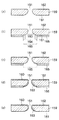
また、インク室ユニット153には、各ノズル孔151に対応して設けられるノズルプレート159を備える。本実施形態では、ノズルプレート表面162と、表面162に続くノズル孔151の内面163と、ノズルプレートの裏面161に続くノズル孔151の周囲部分164とに、撥インク性の皮膜160が形成されている。
[Nozzle plate structure]
Further, the
ノズルプレート159は、金属、セラミックス、シリコン、ガラス、プラスチック等で形成され、好ましくはチタン、クロム、鉄、コバルト、ニッケル、銅、亜鉛、スズ、金等の単一もしくはニッケルーリン合金、スズ−銅−リン合金(リン青銅)、銅−亜鉛合金、ステンレス鋼等の合金や、ポリカーボネイト、プリサルフォン、ABS樹脂(アクリルニトリル・ブタジエン・スチレン供重合)、ポリエチレンテレフタレート、ポリアセタール及び各種の感光性樹脂で形成されている。
The
また、ノズル孔151の内面163とノズルプレートの表面162との境界(ノズル吐出口エッジ部)は、曲面により形成されていることが好ましい。曲面とすることにより、撥インク性の皮膜160がより均一な膜厚で形成され、均一な撥インク性を得ることができる。また、ノズル吐出口周辺でのインク残留物の堆積を抑止することができる。吐出口エッジ部が角張っていると、表面162から内面163にかけてのエッジ部にインクが取り残されやすくなり、インク残留物が堆積しやすくなる。
In addition, the boundary (nozzle outlet edge portion) between the
ノズル吐出口エッジ部の曲面の曲率半径r1は、撥インク性の皮膜160を均一に形成するため、撥インク性の皮膜160の膜厚(1〜10μm)と同等およびそれ以上とすることが好ましい。1μm以上とすることにより、インクの残留を防止する効果を満たすのに十分である。また。ノズル吐出口エッジ部に堆積物が生じたとしても、その影響を十分に低減することができる。また、1μm以下では十分な曲面形状を有しているとはいえず、インクの残留を防止する効果が十分に発揮されないため、堆積物が生じやすくなる。
The radius of curvature r1 of the curved surface of the nozzle outlet edge is preferably equal to or greater than the film thickness (1 to 10 μm) of the ink-
また、ノズル孔151の内面163とノズルプレートの裏面161との境界についても同様に、曲面により形成されていることが好ましく、漏斗状の形状であることが好ましい。吐出口エッジ部における曲面の効果同様、撥インク性の皮膜160がより均一な膜厚で形成され、均一な撥インク性を得ることができる。また、ノズル孔151の内面163とノズルプレートの裏面161との境界が角張っていると、裏面161からノズル孔151の内面163をインク液が満たす際、インクがノズル孔151の内面163にぬれる時間に差が生じる場合がある。この時、インクメニスカス面の高さの位置が一定にならないため、インクの飛翔方向がずれる場合がある。また、インクメニスカス面がノズル孔151の内面から裏面に後退するときは、内面163から裏面161にかけての形状が曲面であるため、気泡の混入を抑止することができるため、インクの吐出方向を安定させることができる。
Similarly, the boundary between the
ノズル孔151の内面163とノズルプレートの裏面161にかけての曲面の曲率半径r2もノズル吐出口エッジ部の曲面の曲率半径r1と同様に、撥インク性の皮膜160を均一に形成するため、撥インク性の皮膜160の膜厚(1〜10μm)と同等およびそれ以上とすることが好ましい。さらに、インクメニスカス面の高さが移動する際の気泡の混入を抑止する観点から、曲率半径r2はインク吐出や充填に不都合を生じさせない範囲で、ノズル長h(ノズルプレートの高さ幅)にできる限り近いことが望ましい。ノズル長hとしては、10〜100μmの範囲であることが好ましい。
Since the curvature radius r2 of the curved surface between the
また、ノズル孔151の内面163からノズルプレートの裏面161にかけての形状は、漏斗状に限定されるものではなく、ノズルプレートの裏面161からノズル吐出口に向かって、ノズル孔151の断面積が小さくなるような形状であれば、特に限定されない。たとえば、テーパー形状を挙げることができる。
The shape from the
〔ノズルプレートの形成方法〕
図5はノズルプレート159の表面162に撥インク性の皮膜160を施す工程を示した図である。
[Method of forming nozzle plate]
FIG. 5 is a view showing a process of applying an ink-
ノズルプレート159の裏面161にノズル孔151とその周囲部分164を除いて適宜レジストテープ166が貼着される(図5(b))。すなわち、このノズルプレート159の裏面161には、漏斗状部分から平坦な裏面161とその周囲部分164を露出させるような大径の孔165を多数設けたレジストテープ166が貼着される。この孔165は、レジストテープ166をノズルプレート159に貼着したあとで打抜き等によって形成することもできる。
A resist
このようにしてレジストテープ166が貼着されたノズルプレート159は、一旦酸で洗浄した後、ニッケルイオンとポリテトフルオロエチレン等の撥水性高分子樹脂の粒子を電荷により分散させた電解液中に浸漬し、ついで、電解液を攪拌しながらその表面に共析メッキを施こす(図5(c))。
The
この共析メッキ処理に使用される成分としては、撥インク性を有するものであれば特に限定されないが、フッ素系高分子、シリコーン系の高分子であることが好ましく、特に、フッ素系の高分子であることが好ましい。フッ素系高分子としては、ポリテトラフルオロエチレン、ポリパーフルオロアルコキシブタジェン、ポリフルオロビニリデン、ポリフルオロビニルおよびポリジパーフルオロアルキルフマレート等を単独にあるいは混合したものが用いられる。 The components used for this eutectoid plating treatment are not particularly limited as long as they have ink repellency, but are preferably fluorine-based polymers and silicone-based polymers, and in particular, fluorine-based polymers. It is preferable that As the fluorine-based polymer, polytetrafluoroethylene, polyperfluoroalkoxybutadiene, polyfluorovinylidene, polyfluorovinyl, polydiperfluoroalkyl fumarate, or the like may be used alone or in combination.
このメッキ層のマトリックスとしては特に制限はなく、ニッケル、銅、銀、亜鉛、錫等の適宜の金属を選ぶことができるが、好ましくは、ニッケルやニッケル−コバルト合金、ニッケル−リン合金、ニッケル−ホウ素合金等の表面硬度が大で、しかも耐摩耗性に優れたのもが選定される。 The matrix of the plating layer is not particularly limited, and an appropriate metal such as nickel, copper, silver, zinc, or tin can be selected. Preferably, nickel, nickel-cobalt alloy, nickel-phosphorus alloy, nickel- A material having a high surface hardness such as boron alloy and having excellent wear resistance is selected.
これにより、フッ素系高分子の粒子は、ニッケルイオンを媒介としてノズルプレート1159の表面162とノズル孔151の内面163及びレジストテープ166の孔165から露出した裏面161に均一の層となって付着する。
Thereby, the fluorine-based polymer particles adhere to the
つぎに、ノズルプレート159に荷重を加えて反りの発生を抑えながら、これを用いたフッ素系高分子の融点以上の温度で加熱する。この加熱により、フッ素系高分子の粒子は、それぞれの部分に融着し、平滑で硬度の大きい撥インク性の皮膜160を形成することができる。
Next, heating is performed at a temperature equal to or higher than the melting point of the fluorine-based polymer using the
撥インク性の皮膜160は、膜厚が薄いと撥インク性が不十分であり、また厚いとインク吐出口の径の精度に影響するため、1〜10μmであることが好ましい。また、皮膜160中のフッ素系高分子の量は、形成された皮膜中60vol%以下であることが好ましく、特に10〜50vol%の範囲であることが好ましい。
The ink-
また、撥インク性皮膜の形成方法としては、他にディップコート法、スプレーコート法等を挙げることができるが、上述した共析メッキ法が好ましく用いられる。 In addition, examples of the method for forming the ink repellent film include a dip coating method and a spray coating method, and the eutectoid plating method described above is preferably used.
その後、ノズルプレート159の裏面161からレジストテープ166を除去し、その部分に接着剤を塗布してノズルプレート159を基体上に固着することにより、ヘッド153を形成することができる。
Then, the
図6はノズルプレート159の裏面161に被覆する他の被覆方法を示した図である。
FIG. 6 is a view showing another coating method for coating the
この方法は、一般の被覆方法と同様に、まずノズルプレート159の裏面161全体に液状のレジスト材167を塗布する(図6(a))。
In this method, similarly to a general coating method, first, a liquid resist
つぎに、この上をマスク部材168で覆って、ノズル孔151の部分とその周囲部分164を露光し(図6(b))、最後にこの露光した部分を溶融除去すれば、図6(c)に示したように、接着剤の塗布部分のみを被覆することができる。
Next, the upper portion is covered with a
〔インク組成物〕
本発明において用いられるインク組成物は、少なくとも色材、ポリマー微粒子、水溶性有機溶媒、及び水を含有する。
[Ink composition]
The ink composition used in the present invention contains at least a coloring material, polymer fine particles, a water-soluble organic solvent, and water.
<色材>
インク組成物に使用される色材は、染料、顔料あるいは染料と顔料とを混合して用いることができるが、記録画像に耐候性を付与する観点から、顔料がより好ましい。顔料の中でも、特に、分散剤により分散されている顔料、自己分散顔料、樹脂により顔料表面を被覆された顔料(マイクロカプセル顔料)、及び高分子グラフト顔料が好ましい。
<Color material>
The coloring material used in the ink composition can be a dye, a pigment, or a mixture of a dye and a pigment, but a pigment is more preferable from the viewpoint of imparting weather resistance to a recorded image. Among the pigments, a pigment dispersed with a dispersant, a self-dispersing pigment, a pigment whose surface is coated with a resin (microcapsule pigment), and a polymer graft pigment are particularly preferable.
マイクロカプセル顔料の樹脂としては、特に限定されないが、水に対して自己分散能あるいは溶解能を有する、またはその機能が何らかの手段によって付加されたものであってもよい。例えば、有機アミンやアルカリ金属を用いて中和することにより、カルボキシル基、スルホン酸基、またはホスホン酸基等のアニオン性基を導入されてなる樹脂が好ましく用いられる。また、同種または異種の一又は二以上のアニオン性基が導入された樹脂であってもよい。本発明においては、塩基をもって中和されて、カルボキシル基が導入された樹脂が好ましく用いられる。 Although it does not specifically limit as resin of a microcapsule pigment, Self-dispersing ability or solubility to water, or the function added by some means may be sufficient. For example, a resin in which an anionic group such as a carboxyl group, a sulfonic acid group, or a phosphonic acid group is introduced by neutralization with an organic amine or alkali metal is preferably used. Further, it may be a resin into which one or two or more anionic groups of the same type or different types are introduced. In the present invention, a resin having a carboxyl group introduced by neutralization with a base is preferably used.
また、これらの樹脂の数平均分子量は、通常、数平均分子量が1,000〜100,000範囲程度のものが好ましく、3、000〜50、000範囲程度のものが特に好ましい。また、この樹脂は有機溶剤に溶解して溶液となるものが好ましい。樹脂の数平均分子量がこの範囲であることにより、顔料における被覆膜として、又はインク組成物における塗膜としての機能を十分に発揮することができる。 Further, the number average molecular weight of these resins is usually preferably about 1,000 to 100,000, and particularly preferably about 3,000 to 50,000. Further, it is preferable that this resin is dissolved in an organic solvent to form a solution. When the number average molecular weight of the resin is within this range, the function as a coating film in the pigment or as a coating film in the ink composition can be sufficiently exhibited.
本発明に用いる顔料としては、特に限定はされないが、具体例としては、オレンジまたはイエロー用の顔料としては、例えば、C.I.ピグメントオレンジ31、C.I.ピグメントオレンジ43、C.I.ピグメントイエロー12、C.I.ピグメントイエロー13、C.I.ピグメントイエロー14、C.I.ピグメントイエロー15、C.I.ピグメントイエロー17、C.I.ピグメントイエロー74、C.I.ピグメントイエロー93、C.I.ピグメントイエロー94、C.I.ピグメントイエロー128、C.I.ピグメントイエロー138、C.I.ピグメントイエロー151、C.I.ピグメントイエロー155、C.I.ピグメントイエロー180、C.I.ピグメントイエロー185等が挙げられる。 Although it does not specifically limit as a pigment used for this invention, As a specific example, as a pigment for orange or yellow, C.I. I. Pigment orange 31, C.I. I. Pigment orange 43, C.I. I. Pigment yellow 12, C.I. I. Pigment yellow 13, C.I. I. Pigment yellow 14, C.I. I. Pigment yellow 15, C.I. I. Pigment yellow 17, C.I. I. Pigment yellow 74, C.I. I. Pigment yellow 93, C.I. I. Pigment yellow 94, C.I. I. Pigment yellow 128, C.I. I. Pigment yellow 138, C.I. I. Pigment yellow 151, C.I. I. Pigment yellow 155, C.I. I. Pigment yellow 180, C.I. I. And CI Pigment Yellow 185.
レッドまたはマゼンタ用の顔料としては、例えば、C.I.ピグメントレッド2、C.I.ピグメントレッド3、C.I.ピグメントレッド5、C.I.ピグメントレッド6、C.I.ピグメントレッド7、C.I.ピグメントレッド15、C.I.ピグメントレッド16、C.I.ピグメントレッド48:1、C.I.ピグメントレッド53:1、C.I.ピグメントレッド57:1、C.I.ピグメントレッド122、C.I.ピグメントレッド123、C.I.ピグメントレッド139、C.I.ピグメントレッド144、C.I.ピグメントレッド149、C.I.ピグメントレッド166、C.I.ピグメントレッド177、C.I.ピグメントレッド178、C.I.ピグメントレッド222等が挙げられる。
Examples of red or magenta pigments include C.I. I. Pigment red 2, C.I. I.
グリーンまたはシアン用の顔料としては、例えば、C.I.ピグメントブルー15、C.I.ピグメントブルー15:2、C.I.ピグメントブルー15:3、C.I.ピグメントブルー16、C.I.ピグメントブルー60、C.I.ピグメントグリーン7等が挙げられる。 Examples of the pigment for green or cyan include C.I. I. Pigment blue 15, C.I. I. Pigment blue 15: 2, C.I. I. Pigment blue 15: 3, C.I. I. Pigment blue 16, C.I. I. Pigment blue 60, C.I. I. And CI Pigment Green 7.
また、ブラック用の顔料としては、例えば、C.I.ピグメントブラック1、C.I.ピグメントブラック6、C.I.ピグメントブラック7等が挙げられる。 Examples of black pigments include C.I. I. Pigment black 1, C.I. I. Pigment black 6, C.I. I. Pigment black 7 and the like.
本発明に用いるインクに含まれる色材の濃度は、使用する色材により最適な値を選択すればよいが、インクの全質量に対し、0.1質量%〜40質量%の範囲にするのが好ましい。より好ましくは、1質量%〜30質量%、さらに好ましくは2質量%〜20質量%である。 The concentration of the color material contained in the ink used in the present invention may be selected to an optimum value depending on the color material to be used, but it should be in the range of 0.1% by mass to 40% by mass with respect to the total mass of the ink. Is preferred. More preferably, they are 1 mass%-30 mass%, More preferably, they are 2 mass%-20 mass%.
色材粒子の体積平均粒子径は、インク吐出性を損なわなければ特に限定はされないが、100nm以下であることが特に好ましい。色材の微細化によって得られる記録媒体上での発色性や透明性向上という従来の効果に加え、ヘッドノズル周縁部に付着するインク残留堆積物の堆積を低減することができる。さらに、吐出口が曲面であるノズル形状との相乗効果により、クリーニングによる負荷を低減する効果を期待することができる。 The volume average particle diameter of the color material particles is not particularly limited as long as the ink ejection property is not impaired, but is particularly preferably 100 nm or less. In addition to the conventional effects of improving color developability and transparency on the recording medium obtained by miniaturizing the color material, it is possible to reduce the accumulation of residual ink deposits adhering to the peripheral edge of the head nozzle. Further, the synergistic effect with the nozzle shape having a curved discharge port can be expected to reduce the load caused by cleaning.
<ポリマー微粒子>
本発明のインク組成物には、着色剤を含まないポリマー微粒子を添加することが好ましい。特に、アニオン性の親水性官能基を有するポリマー微粒子をインクに含有することにより、分散性・安定性の高いインクを得ることができる。
<Polymer fine particles>
It is preferable to add polymer fine particles not containing a colorant to the ink composition of the present invention. In particular, by containing polymer fine particles having an anionic hydrophilic functional group in the ink, an ink having high dispersibility and stability can be obtained.
ポリマー微粒子のインクでの分散方法はエマルジョンに限定するものではなく、溶解していても、コロイダルディスパージョン状態で存在していてもよい。また、ポリマー微粒子は、乳化剤を用いて分散させたものであっても、乳化剤を用いないで分散させたものであってもよい。乳化剤としては、通常、低分子量の界面活性剤が用いられているが、高分子量の界面活性剤を乳化剤として用いることもできる。外殻がアクリル酸、メタクリル酸などにより構成されたカプセル型のポリマー微粒子(粒子の中心部と外縁部で組成を異にしたコア・シェルタイプのポリマー微粒子)を用いることも好ましい。 The method for dispersing the polymer fine particles in the ink is not limited to emulsion, and it may be dissolved or exist in a colloidal dispersion state. Further, the polymer fine particles may be dispersed using an emulsifier or may be dispersed without using an emulsifier. As the emulsifier, a low molecular weight surfactant is usually used, but a high molecular weight surfactant can also be used as an emulsifier. It is also preferable to use capsule type polymer fine particles (core / shell type polymer fine particles having different compositions at the center and outer edge of the particle) whose outer shell is made of acrylic acid, methacrylic acid or the like.
分散手法として、低分子量の界面活性剤を用いていないポリマー微粒子は、高分子量の界面活性剤を用いたポリマー微粒子、乳化剤を使用しないポリマー微粒子を含めてソープフリーラテックスと呼ばれている。例えば上記に記述した、スルホン酸基、カルボキシル基等の水に可溶な基を有するポリマー(可溶化基がグラフト結合しているポリマー、可溶化基を持つ単量体と不溶性の部分を持つ単量体とから得られるブロックポリマー)を乳化剤として用いたポリマー微粒子もこれに含まれる。 As a dispersion method, polymer fine particles not using a low molecular weight surfactant are called soap-free latex, including polymer fine particles using a high molecular weight surfactant and polymer fine particles not using an emulsifier. For example, as described above, a polymer having a water-soluble group such as a sulfonic acid group or a carboxyl group (a polymer in which a solubilizing group is graft-bonded, a monomer having a solubilizing group and an insoluble portion). Polymer fine particles using a block polymer obtained from a monomer as an emulsifier are also included.
本発明では、特にこのソープフリーラテックスを用いることが好ましく、ソープフリーラテックスは従来の乳化剤用いて重合したポリマー微粒子にくらべ、乳化剤がポリマー微粒子の造膜を阻害したり、遊離した乳化剤がポリマー微粒子の造膜後に表面に移動し、顔料とポリマー微粒子の混合した画像膜と記録媒体との接着性すなわち定着性を低下させる懸念がない。 In the present invention, it is particularly preferable to use this soap-free latex. Compared with conventional polymer fine particles polymerized using an emulsifier, the soap-free latex inhibits film formation of the polymer fine particles, or the free emulsifier contains polymer fine particles. There is no concern of moving to the surface after film formation and reducing the adhesion, that is, the fixability, between the image film mixed with the pigment and polymer fine particles and the recording medium.
アニオン性の親水性官能基としては、マイナスの電荷を有するものであれば、特に限定されず用いることができる。中でも、リン酸基、ホスホン酸基、ホスフィン酸基、硫酸基、スルホン酸基、スルフィン酸基またはカルボキシル基が好ましく、ポリマー微粒子の画像定着性付与の観点から、解離度の小さいカルボキシル基が好ましく用いられる。 The anionic hydrophilic functional group is not particularly limited as long as it has a negative charge. Among them, a phosphoric acid group, a phosphonic acid group, a phosphinic acid group, a sulfuric acid group, a sulfonic acid group, a sulfinic acid group or a carboxyl group is preferable, and a carboxyl group having a low dissociation degree is preferably used from the viewpoint of imparting image fixability to polymer fine particles. It is done.
ポリマー微粒子として添加する樹脂成分としては、例えば、アクリル系樹脂、酢酸ビニル系樹脂、スチレン−ブタジエン系樹脂、スチレンイソプレン系樹脂、塩化ビニル系樹脂、アクリル−ウレタン系樹脂、スチレン−アクリル系樹脂、エチレン−アクリル系樹脂、ブタジエン系樹脂、スチレン系樹脂、アイオノマー樹脂などが挙げられるが、これに限定するものではない。 Examples of the resin component added as polymer fine particles include acrylic resins, vinyl acetate resins, styrene-butadiene resins, styrene isoprene resins, vinyl chloride resins, acrylic-urethane resins, styrene-acrylic resins, and ethylene. -Examples include, but are not limited to, acrylic resins, butadiene resins, styrene resins, ionomer resins, and the like.
さらに、ポリマー微粒子の樹脂成分は、親水性部分と疎水性部分とを併せ持つ重合体であることが好ましい。疎水性部分を有することで、ポリマー微粒子の内側に疎水性部分が配向し、外側に親水性部分が効率よく配向される。したがって、ノズルの撥水面に対して、好ましい反親和効果を付与することができ、ノズル孔周辺部でのインクぬれを防ぐことができる。 Furthermore, the resin component of the fine polymer particles is preferably a polymer having both a hydrophilic portion and a hydrophobic portion. By having the hydrophobic part, the hydrophobic part is oriented inside the polymer fine particle, and the hydrophilic part is efficiently oriented outside. Therefore, a preferable anti-affinity effect can be imparted to the water repellent surface of the nozzle, and ink wetting around the nozzle hole can be prevented.
市販のポリマー微粒子の例としては、ジョンクリル(スチレン−アクリル系樹脂エマルジョン、ジョンソンポリマー株式会社製)、ジュリマーET−410(アクリル系樹脂エマルジョン、日本純薬株式会社製)、A−104(アクリル系樹脂エマルジョン、東亞合成株式会社製)、ザイクセン(エチレン−アクリル系樹脂エマルジョン、住友精化株式会社製)、ケミパール(エチレン−アクリル系樹脂エマルジョン、三井化学株式会社製)などが挙げられるが、これに限定するものではない。 Examples of commercially available polymer fine particles include Jonkrill (styrene-acrylic resin emulsion, manufactured by Johnson Polymer Co., Ltd.), Jurimer ET-410 (acrylic resin emulsion, manufactured by Nippon Pure Chemical Co., Ltd.), A-104 (acrylic type). Resin emulsion, manufactured by Toagosei Co., Ltd., Saixen (ethylene-acrylic resin emulsion, manufactured by Sumitomo Seika Co., Ltd.), Chemipearl (ethylene-acrylic resin emulsion, manufactured by Mitsui Chemicals), etc. It is not limited.
色材に対するポリマー微粒子添加量の質量比率は2:1から1:10が好ましく、より好ましくは1:1から1:5である。色材に対するポリマー微粒子添加量の質量比率が2:1より少ないと、樹脂の融着による効果が不足し、耐擦性に対して十分な効果が得られない。また、添加量が1:10より多くてもインクの粘度が高くなりすぎ、吐出信頼性などが悪化する。 The mass ratio of the amount of polymer fine particles added to the colorant is preferably 2: 1 to 1:10, more preferably 1: 1 to 1: 5. When the mass ratio of the amount of polymer fine particles added to the color material is less than 2: 1, the effect of resin fusion is insufficient and a sufficient effect on the abrasion resistance cannot be obtained. Moreover, even if the addition amount is more than 1:10, the viscosity of the ink becomes too high, and the ejection reliability and the like deteriorate.
インクに添加するポリマー微粒子の分子量は融着したときの接着力を鑑みて、5,000以上が好ましい。5,000未満だと、画像の耐擦性および定着性に効果が不足する。 The molecular weight of the polymer fine particles added to the ink is preferably 5,000 or more in view of the adhesive strength when fused. If it is less than 5,000, the effect of the image on the abrasion resistance and the fixing property is insufficient.
本発明で用いるポリマー微粒子の最低造膜温度(MFT)は25℃以下である。最低造膜温度とは、ポリマー微粒子を水に分散させて得られた樹脂エマルジョンをアルミなどの金属板の上に薄く流延し、温度を上昇させていったときに透明な連続フィルムの形成される最低の温度のことをいう。最低造膜温度以下の温度領域では、フィルムは形成されず、白色の粉末状となる。 The minimum film-forming temperature (MFT) of the polymer fine particles used in the present invention is 25 ° C. or less. The minimum film-forming temperature refers to the formation of a transparent continuous film when the resin emulsion obtained by dispersing polymer particles in water is cast thinly on a metal plate such as aluminum and the temperature is raised. This is the lowest temperature. In the temperature region below the minimum film-forming temperature, no film is formed and a white powder is formed.
最低造膜温度が25℃以下のポリマー微粒子を用いることにより、耐擦性の点において、インク画像膜に塑性的な性質を付与し、擦り時に画像膜にかかる力を吸収することによって、耐擦性を向上させることができる。また、ノズルのインクメニスカス面においては、適度な脆さをもつ薄膜を形成することができる。25℃を超えると、室温付近での耐擦性付与効果が低下してしまうのみならず、ノズルのインクメニスカス面において薄膜が形成されない。 By using polymer fine particles having a minimum film forming temperature of 25 ° C. or less, the ink image film is imparted with a plastic property in terms of abrasion resistance, and by absorbing the force applied to the image film during rubbing, the abrasion resistance is increased. Can be improved. In addition, a thin film having moderate brittleness can be formed on the ink meniscus surface of the nozzle. If it exceeds 25 ° C., not only the effect of imparting rubbing resistance near room temperature is lowered, but also a thin film is not formed on the ink meniscus surface of the nozzle.
また、本発明で用いるポリマー微粒子のガラス転移温度Tgは50℃以下であることが好ましい。50℃以下とすることにより、インクメニスカス面に形成される薄膜の強度が十分壊れやすいものになる。50℃を超えた場合、薄膜の強度が強固になるため、インクの吐出性を損なう懸念がある。 The glass transition temperature Tg of the polymer fine particles used in the present invention is preferably 50 ° C. or lower. By setting the temperature to 50 ° C. or lower, the strength of the thin film formed on the ink meniscus surface becomes sufficiently fragile. When the temperature exceeds 50 ° C., the strength of the thin film becomes strong, and there is a concern that ink ejection properties may be impaired.
また、インク画像膜に塑性的な性質を付与し、擦り時に画像膜にかかる力を吸収することによって、耐擦性を向上させることができるので、ポリマー微粒子のガラス転移温度は30℃以下であることがより好ましい。 In addition, the glass transition temperature of the polymer fine particles is 30 ° C. or lower because it imparts plastic properties to the ink image film and absorbs the force applied to the image film during rubbing to improve the abrasion resistance. It is more preferable.
ポリマー微粒子のガラス転移温度Tgは、下記の式Aを用いて算出することができる。 The glass transition temperature Tg of the polymer fine particles can be calculated using the following formula A.
1/Tg=Σ(Xi/Tgi) [式A]
ここで、ポリマー微粒子は、i=1からnまでのn個のモノマー成分が共重合しているとする。Xiはi番目のモノマーの質量分率(ΣXi=1)、Tgiはi番目のモノマーの単独重合体のガラス転移温度(絶対温度)である。ただし、Σはi=1からnまでの和とする。構成するモノマーの種類は同じでも、これらのモノマーの組成比を変えることにより、ポリマー微粒子のTgを制御することができる。
1 / Tg = Σ (Xi / Tgi) [Formula A]
Here, it is assumed that n monomer components from i = 1 to n are copolymerized in the polymer fine particles. Xi is the mass fraction of the i-th monomer (ΣXi = 1), and Tgi is the glass transition temperature (absolute temperature) of the homopolymer of the i-th monomer. Here, Σ is the sum from i = 1 to n. Even if the types of the constituent monomers are the same, the Tg of the polymer fine particles can be controlled by changing the composition ratio of these monomers.
ポリマー微粒子の体積平均粒径は、インク吐出性を損なわなければ特に限定はされないが、インクメニスカス面での薄膜形成の点からは100nm以下であることが特に好ましい。この範囲とすることにより、ノズル近傍付近で好適な脆さをもつポリマーの薄膜を形成することができる。また、粗大な粒子数を低減できると同時に、全体の粒子サイズ自体が小さく微細なものとなるので、粒度分布に対して相対的に大きな粒子が存在しても膜の均一性に与える影響を少なくできる。また、ノズル周縁部での残留物の堆積も低減することができるので、吐出口が曲面であるノズル形状との相乗効果により、クリーニング負荷を低減する効果を期待することができる。 The volume average particle size of the polymer fine particles is not particularly limited as long as the ink ejection property is not impaired, but is particularly preferably 100 nm or less from the viewpoint of forming a thin film on the ink meniscus surface. By setting it within this range, a polymer thin film having suitable brittleness can be formed in the vicinity of the nozzle. In addition, the number of coarse particles can be reduced, and at the same time, the overall particle size itself is small and fine, so even if relatively large particles are present in the particle size distribution, the influence on film uniformity is reduced. it can. Moreover, since the accumulation of the residue at the nozzle peripheral portion can be reduced, an effect of reducing the cleaning load can be expected due to a synergistic effect with the nozzle shape in which the discharge port is a curved surface.
ポリマー微粒子の粒径分布に関しては、体積平均粒径(Mv)と数平均粒径(Mn)との比(体積平均粒径Mv/数平均粒径Mn)は、1以上1.5以下であることが好ましく、より好ましくは1以上1.35以下である。 Regarding the particle size distribution of the polymer fine particles, the ratio of the volume average particle size (Mv) to the number average particle size (Mn) (volume average particle size Mv / number average particle size Mn) is 1 or more and 1.5 or less. It is preferable that it is 1 or more and 1.35 or less.
前記体積平均粒径、数平均粒径を含む粒度分布の測定方法としては、静的光散乱法、動的光散乱法、遠心沈降法が挙げられる。その中でも、レーザードップラー効果を利用した動的光散乱法は、小サイズまで粒径測定が可能であり、特に好ましい。動的光散乱法による粒径測定は、例えば、マイクロトラックUPA(日機装株式会社製)を用いて行うことができる。体積平均粒径とは、粒子体積で重み付けした平均粒径であり、粒子の集合において、個々の粒子の直径にその粒子の体積を乗じたものの総和を、粒子の総体積で割ったものであり、下記式B−1で表される。 Examples of the method for measuring the particle size distribution including the volume average particle size and the number average particle size include a static light scattering method, a dynamic light scattering method, and a centrifugal sedimentation method. Among them, the dynamic light scattering method using the laser Doppler effect is particularly preferable because it can measure the particle size up to a small size. The particle size measurement by the dynamic light scattering method can be performed using, for example, Microtrac UPA (manufactured by Nikkiso Co., Ltd.). The volume average particle size is an average particle size weighted by the particle volume. In the set of particles, the sum of the diameter of each particle multiplied by the volume of the particle is divided by the total volume of the particle. And represented by the following formula B-1.
体積平均粒径 Mv=Σ(FiMi4)/Σ(FiMi3) [式B−1]
Fi:粒径がMiである粒子の数(分率)
数平均粒径とは、粒子の集合において、個々の粒子の直径の総和を、粒子の総数で割ったものであり、下記式B−2で表される。
Volume average particle diameter Mv = Σ (FiMi 4 ) / Σ (FiMi 3 ) [Formula B-1]
Fi: Number of particles having a particle size Mi (fraction)
The number average particle diameter is obtained by dividing the sum of the diameters of individual particles by the total number of particles in a set of particles, and is represented by the following formula B-2.
数平均粒径 Mn=ΣFiMi/ΣFi [式B−2]
Fi:粒径がMiである粒子の数(分率)
体積平均粒径と数平均粒径との関係としては、体積平均粒径Mvが、数平均粒径Mnと等しい又は数平均粒径Mnより大きい関係(体積平均粒径≧数平均粒径)にある。従って、完全に粒径が同一の粒子の集合において、両者の値は等しくなり、体積平均粒径Mvと数平均粒径Mnとの比(体積平均粒径Mv/数平均粒径Mn)は1となる。また、体積平均粒径Mvと数平均粒径Mnとの比が大きくなるほど、粒径分布が広いことを表す。なお、体積平均粒径及び数平均粒径については、室井 宗一著「高分子ラテックスの化学」高分子刊行会、119頁に記載がある。
Number average particle diameter Mn = ΣFiMi / ΣFi [Formula B-2]
Fi: Number of particles having a particle size Mi (fraction)
As the relationship between the volume average particle size and the number average particle size, the volume average particle size Mv is equal to or greater than the number average particle size Mn (volume average particle size ≧ number average particle size). is there. Therefore, in a set of particles having the same particle size, both values are equal, and the ratio of the volume average particle size Mv to the number average particle size Mn (volume average particle size Mv / number average particle size Mn) is 1. It becomes. In addition, the larger the ratio between the volume average particle size Mv and the number average particle size Mn, the wider the particle size distribution. The volume average particle number and the number average particle size are described in Soichi Muroi, “Polymer Latex Chemistry”, Polymer Publishing Association, page 119.
インク中のポリマー微粒子に粗大粒子が存在する場合、インクの吐出信頼性に非常に大きな影響を与えることがあるため好ましくない。特に本発明のように室温で造膜性を有する樹脂を用いる場合は、粗大粒子の影響が顕著になる。すなわち、粗大粒子が多い(粒度分布形状がブロード)と、ヘッドのノズルにおいて吐出不良を起こしたり、吐出不良までにはいたらずとも、粗大粒子によりノズル近傍にインク残留物が形成されて、インク滴の吐出方向にバラツキが生じる場合がある。 In the case where coarse particles are present in the polymer fine particles in the ink, the ink ejection reliability may be greatly affected, which is not preferable. In particular, when a resin having a film-forming property at room temperature is used as in the present invention, the influence of coarse particles becomes significant. In other words, if there are many coarse particles (the particle size distribution shape is broad), even if ejection failure occurs in the nozzle of the head or the ejection failure does not occur, ink residues are formed in the vicinity of the nozzles due to the coarse particles. There may be variations in the discharge direction.
これらの粗大粒子を除去する方法としては、公知の遠心分離法、精密濾過法等を用いることができる。 As a method for removing these coarse particles, a known centrifugal separation method, microfiltration method, or the like can be used.
遠心分離法としては、市販の遠心分離器を用いることができる。加える遠心力の大きさは重力加速度の10倍〜1000000倍が好ましい。 A commercially available centrifuge can be used as the centrifugation method. The magnitude of the centrifugal force to be applied is preferably 10 times to 1 million times the gravitational acceleration.
精密濾過法に用いるフィルターとしては、様々な材質の物を用いることができる。即ち、セルロース、アセチルセルロース、ポリフッ化ビニリデン、ポリエーテルスルホン、ポリテトラフルオロエチレン、ポリカーボネート、グラスファイバー、ポリプロピレン等が好適に挙げられる。また、フィルターの形態も、メンブレンフィルター及びデプスフィルターのいずれも、好ましく用いられる。濾過に用いる前記フィルターの孔径は、0.1〜10μmが好ましく、0.2〜5μmがより好ましく、0.2〜0.5μmが最も好ましい。また、濾過を行う際に、孔径の大きなフィルターで濾過した後、より孔径の小さなフィルターで再度濾過することが好ましい。粗大粒子が多く、ろ過性が悪い場合は、分散液に分散剤を添加してろ過性を向上させることができる。 As a filter used in the microfiltration method, various materials can be used. That is, cellulose, acetyl cellulose, polyvinylidene fluoride, polyethersulfone, polytetrafluoroethylene, polycarbonate, glass fiber, polypropylene, and the like are preferable. Moreover, as for the form of a filter, both a membrane filter and a depth filter are preferably used. The pore size of the filter used for filtration is preferably 0.1 to 10 μm, more preferably 0.2 to 5 μm, and most preferably 0.2 to 0.5 μm. Moreover, when filtering, after filtering with a filter with a large hole diameter, it is preferable to filter again with a filter with a smaller hole diameter. If there are many coarse particles and the filterability is poor, a dispersant can be added to the dispersion to improve the filterability.
また、ポリマー微粒子をインク内に2種以上混合させて使用してもよい。それぞれのポリマー微粒子を各々単独でインク中に分散していてもよいし、コア部とシェル部からなるコアシェル構造をとってもよい。また、シェル部がコア部を完全に被覆している形態のみならず、コア部の一部を被覆している形態であってもよい。また、第一の樹脂成分の層中に第二の樹脂成分の層が島上に分散して包まれている形態でもよいし、第一の樹脂層が表層を形成するポリマー微粒子表面に、第二の樹脂粒子を点分散させた形態でもよい。 Further, two or more kinds of polymer fine particles may be mixed in the ink. Each polymer fine particle may be dispersed alone in the ink, or may have a core-shell structure composed of a core portion and a shell portion. Moreover, not only the form which the shell part has coat | covered the core part completely, but the form which coat | covered a part of core part may be sufficient. Further, the second resin component layer may be dispersed and wrapped on the island in the first resin component layer, or the first resin layer may be formed on the surface of the polymer fine particles forming the surface layer. Alternatively, the resin particles may be dispersed in the form of dots.
ポリマー微粒子の体積平均粒径は、色材粒子の体積平均粒子径より小さいことが好ましい。色材粒子の平均粒径がポリマー微粒子の平均粒径より小さいと、色材粒子とポリマー微粒子との衝突頻度が高まり、ポリマー微粒子同士の接触・凝集頻度を低下させ、インクメニスカス面での造膜を妨げてしまい、本発明の効果を阻害する懸念がある。色材粒子の平均粒径が大きい分には、ポリマー微粒子よりも分散が安定状態にあるので、ポリマー微粒子の薄膜形成に影響を及ぼさない。また、色材粒子間にポリマー微粒子が入り込みやすくなり、造膜による色材粒子間の接着効果向上による定着・耐擦性向上が期待できる。 The volume average particle diameter of the polymer fine particles is preferably smaller than the volume average particle diameter of the colorant particles. When the average particle diameter of the color material particles is smaller than the average particle diameter of the polymer fine particles, the collision frequency between the color material particles and the polymer fine particles increases, and the contact / aggregation frequency between the polymer fine particles decreases, thereby forming a film on the ink meniscus surface. There is a concern that the effect of the present invention may be hindered. Since the dispersion of the color material particles is larger than that of the polymer fine particles, the average particle size of the color material particles is not affected. In addition, polymer fine particles can easily enter between the color material particles, and improvement of fixing and abrasion resistance can be expected by improving the adhesion effect between the color material particles by film formation.
色材の体積平均粒子径とポリマー微粒子の体積平均粒子径の比は1:1〜10:1が好ましく、より好ましくは3:1〜10:1である。10:1を越え、顔料粒子サイズが大きくなりすぎると、ポリマー微粒子による顔料粒子間の接着効果が不足し、耐擦性が損なわれる。 The ratio of the volume average particle diameter of the coloring material to the volume average particle diameter of the polymer fine particles is preferably 1: 1 to 10: 1, more preferably 3: 1 to 10: 1. If it exceeds 10: 1 and the pigment particle size becomes too large, the adhesion effect between the pigment particles by the polymer fine particles is insufficient, and the abrasion resistance is impaired.
<添加剤>
本発明のインクに添加するpH調整剤としては中和剤として、有機塩基、無機アルカリ塩基を用いることができる。pH調整剤はインクジェット用インクの保存安定性を向上させる目的で、該インクジェット用インクがpH6〜10となるように添加するのが好ましい。
<Additives>
As the pH adjuster added to the ink of the present invention, an organic base or an inorganic alkali base can be used as a neutralizing agent. The pH adjusting agent is preferably added so that the inkjet ink has a pH of 6 to 10 for the purpose of improving the storage stability of the inkjet ink.
本発明のインクは、乾燥によってインクジェットヘッドのノズルが詰まるのを防止する目的から、水溶性有機溶媒を含有することが好ましい。このような水溶性有機溶媒には、湿潤剤及び浸透剤が含まれる。 The ink of the present invention preferably contains a water-soluble organic solvent for the purpose of preventing clogging of the nozzles of the inkjet head due to drying. Such water-soluble organic solvents include wetting agents and penetrants.
水溶性有機溶媒としては、例えば、多価アルコール類、多価アルコール類誘導体、含窒素溶媒、アルコール類、含硫黄溶媒等が挙げられる。具体例としては、多価アルコール類では、エチレングリコール、ジエチレングリコール、プロピレングリコール、ブチレングリコール、トリエチレングリコール、1、5−ペンタンジオール、1,2,6−ヘキサントリオール、グリセリン等が挙げられる。多価アルコール誘導体としては、エチレングリコールモノメチルエーテル、エチレングリコールモノエチルエーテル、エチレングリコールモノブチルエーテル、ジエチレングリコールモノメチルエーテル、ジエチレングリコールモノエチルエーテル、ジエチレングリコールモノブチルエーテル、プロピレングリコールモノブチルエーテル、ジプロピレングリコールモノブチルエーテル、ジグリセリンのエチレンオキサイド付加物等が挙げられる。含窒素溶媒としては、ピロリドン、N−メチル−2−ピロリドン、シクロヘキシルピロリドン、トリエタノールアミン等が、アルコール類としてはエタノール、イソプロピルアルコール、ブチルアルコール、ベンジルアルコール等のアルコール類が、含硫黄溶媒としては、チオジエタノール、チオジグリセロール、スルフォラン、ジメチルスルホキシド等が挙げられる。その他、炭酸プロピレン、炭酸エチレン等を用いることもできる。 Examples of the water-soluble organic solvent include polyhydric alcohols, polyhydric alcohol derivatives, nitrogen-containing solvents, alcohols, sulfur-containing solvents, and the like. Specific examples of polyhydric alcohols include ethylene glycol, diethylene glycol, propylene glycol, butylene glycol, triethylene glycol, 1,5-pentanediol, 1,2,6-hexanetriol, and glycerin. Examples of polyhydric alcohol derivatives include ethylene glycol monomethyl ether, ethylene glycol monoethyl ether, ethylene glycol monobutyl ether, diethylene glycol monomethyl ether, diethylene glycol monoethyl ether, diethylene glycol monobutyl ether, propylene glycol monobutyl ether, dipropylene glycol monobutyl ether, and diglycerin. Examples include ethylene oxide adducts. Examples of nitrogen-containing solvents include pyrrolidone, N-methyl-2-pyrrolidone, cyclohexyl pyrrolidone, and triethanolamine. Examples of alcohols include alcohols such as ethanol, isopropyl alcohol, butyl alcohol, and benzyl alcohol. Thiodiethanol, thiodiglycerol, sulfolane, dimethyl sulfoxide and the like. In addition, propylene carbonate, ethylene carbonate, or the like can be used.
水溶性有機溶媒は、単独で使用しても、2種類以上混合して使用してもよい。水溶性有機溶媒の含有量は処理液の全質量に対し、60質量%以下であることが好ましい。60質量%以上よりも多い場合はインクの粘度が増加し、インクジェットヘッドからの吐出性が悪化することがある。 A water-soluble organic solvent may be used independently or may be used in mixture of 2 or more types. The content of the water-soluble organic solvent is preferably 60% by mass or less with respect to the total mass of the treatment liquid. When the amount is more than 60% by mass or more, the viscosity of the ink increases, and the ejectability from the inkjet head may deteriorate.
本発明に係るインクには、界面活性剤を含有することができる。 The ink according to the present invention can contain a surfactant.
界面活性剤の例としては、炭化水素系では脂肪酸塩、アルキル硫酸エステル塩、アルキルベンゼンスルホン酸塩、アルキルナフタレンスルホン酸塩、ジアルキルスルホコハク酸塩、アルキルリン酸エステル塩、ナフタレンスルホン酸ホルマリン縮合物、ポリオキシエチレンアルキル硫酸エステル塩等のアニオン系界面活性剤や、ポリオキシエチレンアルキルエーテル、ポリオキシエチレンアルキルアリルエーテル、ポリオキシエチレン脂肪酸エステル、ソルビタン脂肪酸エステル、ポリオキシエチレンソルビタン脂肪酸エステル、ポリオキシエチレンアルキルアミン、グリセリン脂肪酸エステル、オキシエチレンオキシプロピレンブロックコポリマー等のノニオン系界面活性剤が好ましい。また、アセチレン系ポリオキシエチレンオキシド界面活性剤であるSURFYNOLS(AirProducts&Chemicals社)も好ましく用いられる。また、N,N−ジメチル−N−アルキルアミンオキシドのようなアミンオキシド型の両性界面活性剤等も好ましい。 Examples of surfactants include fatty acid salts, alkyl sulfate esters, alkylbenzene sulfonates, alkyl naphthalene sulfonates, dialkyl sulfosuccinates, alkyl phosphate esters, naphthalene sulfonate formalin condensates, Anionic surfactants such as oxyethylene alkyl sulfate esters, polyoxyethylene alkyl ethers, polyoxyethylene alkyl allyl ethers, polyoxyethylene fatty acid esters, sorbitan fatty acid esters, polyoxyethylene sorbitan fatty acid esters, polyoxyethylene alkylamines Nonionic surfactants such as glycerin fatty acid ester and oxyethyleneoxypropylene block copolymer are preferred. Further, SURFYNOLS (Air Products & Chemicals), which is an acetylene-based polyoxyethylene oxide surfactant, is also preferably used. An amine oxide type amphoteric surfactant such as N, N-dimethyl-N-alkylamine oxide is also preferred.
更に、特開昭59−157636号の第(37)〜(38)頁、リサーチ・ディスクロージャーNo.308119(1989年)記載の界面活性剤として挙げたものも使うことができる。また、特開2003−322926号、特開2004−325707号、特開2004−309806号の各公報に記載されているようなフッ素(フッ化アルキル系)系、シリコーン系の界面活性剤も用いることができる。 これら表面張力調整剤は消泡剤としても使用することができ、フッ素系、シリコーン系化合物やEDTAに代表されるキレート剤等も使用することができる。 Further, pages (37) to (38) of JP-A-59-157636, Research Disclosure No. The surfactants described in 308119 (1989) can also be used. In addition, fluorine (fluorinated alkyl) and silicone surfactants as described in JP-A Nos. 2003-322926, 2004-325707, and 2004-309806 are also used. Can do. These surface tension modifiers can also be used as antifoaming agents, and fluorine-based, silicone-based compounds, chelating agents represented by EDTA, and the like can also be used.
本発明のインクの表面張力は、10〜50mN/mであることが好ましく、浸透性記録媒体への浸透性、あるいは非浸透媒体へのぬれ性と液滴の微液滴化および吐出信頼性の両立の観点からは、15〜45mN/mであることが更に好ましい。 The surface tension of the ink of the present invention is preferably from 10 to 50 mN / m, and the penetrability to the permeable recording medium or the wettability to the non-penetrable medium and the droplet formation and ejection reliability of the droplet. From the viewpoint of compatibility, it is more preferably 15 to 45 mN / m.
本発明のインクの粘度は、1.0〜20.0cPであることが好ましい。 The viscosity of the ink of the present invention is preferably 1.0 to 20.0 cP.
その他必要に応じ、pH 緩衝剤、酸化防止剤、防カビ剤、粘度調整剤、導電剤、紫外線吸収剤、等も添加することができる。 In addition, pH buffering agents, antioxidants, fungicides, viscosity modifiers, conductive agents, ultraviolet absorbers, and the like can be added as necessary.
次に、実施例を挙げて本発明を更に具体的に説明するが、本発明はこれに限定されるものではない。 Next, the present invention will be described more specifically with reference to examples. However, the present invention is not limited thereto.
(顔料分散物の作製)
<顔料分散物A>
分散剤として、メタクリル酸(A)/ベンジルメタクリレート(B)/エトキシトリエチレングリコールメタクリレート(C)の、ABC型のブロックポリマー(A:B:C=13:4:10(モル比)、数平均分子量=3,000)をポリマー分散剤として用いた。そして、該ポリマー30gを、水酸化カリウム45%の水溶液9g及び脱イオン水261gと混合して合計300gとし、均質な10%ポリマー溶液を得るまで中和した。次いで、このポリマー溶液の全量に、C.I.Pigment Red−122を150g、及び脱イオン水550gを加えて混合し、ディスパー分散機にて0.5時間撹拌して予備混合物を得た。次いで、この予備混合物を内容量2リットル二重タンクに入れ、18℃の冷水で冷却しながら、ディスパー羽根にて攪拌しつつ、超音波ホモジナイザーUS−1200T型((株)日本精機製作所製)で36mmφのチップを用いて30分間バッチ照射を行った。この時の振動振幅は28μm、超音波照射エネルギー密度は110W/cm2であった。こうして得られた顔料の分散液を顔料分散液Aは、顔料濃度が15%であり、そして動的光散乱法粒径測定器(マイクロトラックUPA)で測定した顔料の体積平均粒径は、69nmであった。
(Preparation of pigment dispersion)
<Pigment dispersion A>
As a dispersant, methacrylic acid (A) / benzyl methacrylate (B) / ethoxytriethylene glycol methacrylate (C), an ABC type block polymer (A: B: C = 13: 4: 10 (molar ratio), number average) Molecular weight = 3,000) was used as the polymer dispersant. Then, 30 g of the polymer was mixed with 9 g of an aqueous solution of 45% potassium hydroxide and 261 g of deionized water to make a total of 300 g, and neutralized until a homogeneous 10% polymer solution was obtained. The total amount of this polymer solution was then added to C.I. I. Pigment Red-122 (150 g) and deionized water (550 g) were added and mixed, and the mixture was stirred with a disper disperser for 0.5 hour to obtain a premix. Next, the preliminary mixture was placed in a double tank with an internal volume of 2 liters, stirred with a disperse blade while being cooled with cold water of 18 ° C., and ultrasonic homogenizer US-1200T type (manufactured by Nippon Seiki Seisakusho). Batch irradiation was performed using a 36 mmφ tip for 30 minutes. At this time, the vibration amplitude was 28 μm and the ultrasonic irradiation energy density was 110 W / cm 2 . The pigment dispersion A thus obtained has a pigment concentration of 15%, and the volume average particle diameter of the pigment measured with a dynamic light scattering particle size analyzer (Microtrac UPA) is 69 nm. Met.
<顔料分散物B>
分散剤として、メタクリル酸(A)/ベンジルメタクリレート(B)/エトキシトリエチレングリコールメタクリレート(C)の、ABC型のブロックポリマー(A:B:C=13:4:10(モル比)、数平均分子量=3,000)をポリマー分散剤として用いた。そして、該ポリマー30gを、水酸化カリウム45%の水溶液9g及び脱イオン水261gと混合して合計300gとし、均質な10%ポリマー溶液を得るまで中和した。次いで、このポリマー溶液の全量に、C.I.Pigment Red−122を150g、及び脱イオン水550gを加えて混合し、ディスパー分散機にて0.5時間撹拌して予備混合物を得た。次いで、この予備混合物を、アルティマイザーHJP−25003型((株)スギノマシン製)を用いて245MPaの圧力で2回分散を行った。得られた顔料の分散液を顔料分散液Bとした。こうして得られた顔料の分散液を顔料分散液Bは、顔料濃度が15%であり、そして動的光散乱法粒径測定器(マイクロトラックUPA)で測定した顔料の体積平均粒径は110nmであった。
<Pigment dispersion B>
As a dispersant, methacrylic acid (A) / benzyl methacrylate (B) / ethoxytriethylene glycol methacrylate (C), an ABC type block polymer (A: B: C = 13: 4: 10 (molar ratio), number average) Molecular weight = 3,000) was used as the polymer dispersant. Then, 30 g of the polymer was mixed with 9 g of an aqueous solution of 45% potassium hydroxide and 261 g of deionized water to make a total of 300 g, and neutralized until a homogeneous 10% polymer solution was obtained. The total amount of this polymer solution was then added to C.I. I. Pigment Red-122 (150 g) and deionized water (550 g) were added and mixed, and the mixture was stirred with a disper disperser for 0.5 hour to obtain a premix. Subsequently, this preliminary mixture was dispersed twice at a pressure of 245 MPa using an optimizer HJP-25003 type (manufactured by Sugino Machine Co., Ltd.). The obtained pigment dispersion was designated as Pigment Dispersion B. The pigment dispersion B thus obtained has a pigment concentration of 15%, and the volume average particle diameter of the pigment measured with a dynamic light scattering particle size analyzer (Microtrac UPA) is 110 nm. there were.
(インクの作製)
<インク1〜12の作製>
上記で作製した顔料分散物に、各種ポリマー微粒子分散液、グリセリン、ジエチレングリコール、オルフィンE1010(日信化学工業製)、イオン交換水を所定の質量比(下記)になるように調液し、混合攪拌を行なった。最後に、インクは、調液後、平均孔径0.5μmのアセチルセルロース製メンブレンフィルタ(富士写真フイルム製)で濾過し、粗大粒子を除去した。なお、ポリマー微粒子1を用いて調液したインクをインク1とし、ポリマー微粒子2を用いて調液したインクをインク2とした。以下、ポリマー微粒子3から12についても同様である。
(Preparation of ink)
<Preparation of inks 1 to 12>
Various pigment fine particle dispersions, glycerin, diethylene glycol, Olfine E1010 (manufactured by Nissin Chemical Industry Co., Ltd.), and ion-exchanged water are mixed into the pigment dispersion prepared above so as to have a predetermined mass ratio (below), and mixed and stirred. Was done. Finally, the ink was filtered and filtered through an acetylcellulose membrane filter (manufactured by Fuji Photo Film) having an average pore size of 0.5 μm to remove coarse particles. The ink prepared using the polymer fine particles 1 was designated as ink 1, and the ink prepared using the polymer fine particles 2 was designated as ink 2. The same applies to the
≪組成比≫
・ 顔料分散物 5質量%
・ ポリマー微粒子1〜12 10質量%
・ グリセリン 20質量%
・ ジエチレングリコール 10質量%
・ オルフィンE1010(日信化学工業製) 1質量%
・ イオン交換水 残部
顔料分散物は、インク1から10および12は顔料分散物Aを用い、インク11は顔料分散物Bを用いて調液を行った。
≪Composition ratio≫
・ Pigment dispersion 5% by mass
・ Polymer fine particles 1-12 10% by mass
・ Glycerin 20% by mass
・ Diethylene glycol 10% by mass
・ Olfin E1010 (manufactured by Nissin Chemical Industry) 1% by mass
-Ion-exchanged water The remaining pigment dispersion was prepared using pigment dispersion A for inks 1 to 10 and 12 and pigment dispersion B for ink 11.
また、ポリマー微粒子1から12は以下に示すポリマー微粒子を用いた。
ポリマー微粒子1:ジョンクリル537(ジョンソンポリマー(株)製)
ポリマー微粒子2:アロンHD−5(東亞合成(株)製)
ポリマー微粒子3:ウルトラゾールB−400H(ガンツ化成(株)製)
ポリマー微粒子4〜7:ザイクセンL(住友精化(株)製)
ポリマー微粒子8:ジョンクリル775(ジョンソンポリマー(株)製)
ポリマー微粒子9:ジョンクリル352(ジョンソンポリマー(株)製)
ポリマー微粒子10,11:ジョンクリル7600(ジョンソンポリマー(株)製)
ポリマー微粒子12:ジョンクリル1535(ジョンソンポリマー(株)製)
本発明におけるポリマー微粒子の体積平均粒径Mvと数平均粒径Mnとの比(Mv/Mn)は、ポリマー微粒子を10質量%含んだ水性分散液でマイクロトラックUPA(日機装(株)製)にて測定したものを用いた。
For the polymer fine particles 1 to 12, the following polymer fine particles were used.
Polymer fine particles 1: Jonkrill 537 (manufactured by Johnson Polymer Co., Ltd.)
Polymer fine particle 2: Aron HD-5 (manufactured by Toagosei Co., Ltd.)
Polymer fine particle 3: Ultrasol B-400H (manufactured by Ganz Kasei Co., Ltd.)
Polymer
Polymer fine particle 8: John Krill 775 (manufactured by Johnson Polymer Co., Ltd.)
Polymer fine particle 9: John Krill 352 (manufactured by Johnson Polymer Co., Ltd.)
Polymer fine particles 10 and 11: John Krill 7600 (manufactured by Johnson Polymer Co., Ltd.)
Polymer fine particle 12: John Krill 1535 (manufactured by Johnson Polymer Co., Ltd.)
The ratio (Mv / Mn) between the volume average particle diameter Mv and the number average particle diameter Mn of the polymer fine particles in the present invention is Microtrac UPA (manufactured by Nikkiso Co., Ltd.) using an aqueous dispersion containing 10% by mass of polymer fine particles. What was measured was used.
なお、ポリマー微粒子4〜7のMv/Mnの値に関しては、ポリマー微粒子を含む水性分散液作製時において、粗大粒子をろ過する際に、遠心分離法を用いる場合は回転数や回転時間、あるいは精密濾過法を用いる場合は、アセチルセルロース製メンブレンフィルターでろ過を行う場合はフィルターの孔径サイズやろ過回数によって、値を調整した。
Regarding the Mv / Mn values of the
ポリマー微粒子の最低造膜温度(MFT)、ガラス転移温度(Tg)の測定法については、[発明を実施するための最良の形態]に記載した測定方法により測定を行った。 About the measuring method of the minimum film forming temperature (MFT) and glass transition temperature (Tg) of a polymer fine particle, it measured by the measuring method described in [Best Mode for Carrying Out the Invention].
(ノズルプレートの作製)
ノズルプレートは図5に示した方法により作製した。また、実施例に用いたノズルプレートの断面図を図7に示す。ノズル1〜4は、ノズル内面から裏面にかけての形状が、漏斗状(エッジなし)であり、ノズル5、6は、テーパ状(エッジあり)である。漏斗状、テーパ状の形状ともインク吐出口に向うにつれて、吐出口の断面積が小さくなっているが、ノズル1〜4は、ノズル内面から裏面にかけてノズル内部に凸となる曲線により形成されている。また、ノズル5、6はノズル内面から裏面にかけて直線により形成され、吐出口内部は、略円錐形状である。また、吐出口のエッジ部の形状は、ノズル1〜3及び6が、曲面(エッジなし)であり、ノズル4、5は角面(エッジあり)である。
(Preparation of nozzle plate)
The nozzle plate was produced by the method shown in FIG. Moreover, sectional drawing of the nozzle plate used for the Example is shown in FIG. The nozzles 1 to 4 have a funnel shape (no edge) from the nozzle inner surface to the back surface, and the nozzles 5 and 6 are tapered (with an edge). Both the funnel-shaped and tapered shapes have smaller cross-sectional areas of the discharge ports toward the ink discharge ports, but the nozzles 1 to 4 are formed by curves that protrude from the nozzle inner surface to the back surface. . Moreover, the nozzles 5 and 6 are formed in a straight line from the inner surface of the nozzle to the rear surface, and the inside of the discharge port has a substantially conical shape. In addition, as for the shape of the edge portion of the discharge port, the nozzles 1 to 3 and 6 are curved surfaces (without edges), and the
撥インク性処理は、フッ素樹脂を用いて、ノズル1はノズルの表面のみ、ノズル2は、ノズルの表面・内壁・裏面に行った。また、ノズル3は、シリコーン樹脂を用いて、ノズルの表面・内壁・裏面に行った。ノズル4から6は、フッ素樹脂を用いて、ノズルの表面・内壁・裏面に処理を行った。
The ink repellency treatment was performed using fluororesin, the nozzle 1 only on the surface of the nozzle, and the nozzle 2 on the surface / inner wall / back surface of the nozzle. The
[評価]
上記で作製したノズルプレートを具備したヘッドを用いて、処方したインクを約7plの打滴量で付与し、以下の評価を行った。印字用の記録媒体には特菱両面アート紙(三菱製紙(株)製)を用いた。
[Evaluation]
Using the head equipped with the nozzle plate prepared above, the prescribed ink was applied in a droplet ejection amount of about 7 pl, and the following evaluation was performed. As a recording medium for printing, special double-sided art paper (Mitsubishi Paper Co., Ltd.) was used.
(吐出方向バラツキ)
本発明のヘッドノズルに評価インクを充填し、25℃50RHの環境下で文字画像を連続印字し、印字画像に乱れ状態(インクの飛散及びドット抜けなど)が確認される回数が5回に達するまでの時間を評価した。
◎:1日以上印字しても5回に達しない
○:1日以内に5回に達する
△:6時間以内に5回に達する
×:1時間以内に5回に達する
(クリーニング負荷)
本発明のヘッドノズルに評価インクを充填し、ノズルチェックを行い、全てのノズルからインクが打滴していることを確認後、25℃50RHの環境下で1ヶ月以上放置し、同様にノズルチェックを行い、印字率が100%に回復するまでのクリーニング必要回数によって、クリーニングに要する負荷を評価した。
◎:1回実施で印字率100%
○:3回実施で印字率100%
△:5回実施で印字率100%
×:5回以上実施しても100%に回復しない
(耐擦性)
本発明で用いるノズルを用いた打滴描画では、ノズルからの吐出が良好に行われないインクが存在したため、全ての評価インクに対して耐擦性を比較するため、塗布によりサンプルを作製し耐擦性評価を行った。
(Discharge direction variation)
The head nozzle of the present invention is filled with evaluation ink, and a character image is continuously printed in an environment of 25 ° C. and 50 RH, and the number of times that the printed image is confirmed to be disordered (such as ink scattering and missing dots) reaches 5 times. The time until was evaluated.
◎: 5 times within 1 day even if printed over 1 day ○: 5 times within 1 day △: 5 times within 6 hours ×: 5 times within 1 hour (cleaning load)
After filling the head nozzle of the present invention with the evaluation ink and performing a nozzle check and confirming that ink has been ejected from all nozzles, the ink is left in an environment of 25 ° C. and 50 RH for one month or longer, and the nozzle check is performed in the same manner And the load required for cleaning was evaluated based on the number of cleanings required until the printing rate recovered to 100%.
◎: 100% printing rate when implemented once
○: Printing rate is 100% when implemented three times
Δ: Print rate 100% after 5 runs
X: Even if it implements 5 times or more, it does not recover to 100% (Abrasion resistance)
In droplet ejection drawing using the nozzles used in the present invention, there were inks that were not ejected favorably from the nozzles. Rubbing evaluation was performed.
処方した評価インクをA6サイズの特菱アート紙にバー塗布(#3)し、塗布サンプルを24時間乾燥させた。このようにして作製したサンプルを、25℃50RHの環境下で、特菱アート紙を上から被せ、1.5kg/cm2の加重で20往復擦り、塗布サンプルの色材剥れ状態を評価した。
◎:擦った部分で全く色材剥れがわからない
○:擦った部分でほとんど色材剥れがわからず、見た目上問題ない
△:擦った部分で色材剥れが認識されるが、許容範囲
×:アート紙表面の白地まで露出している部分があり、許容範囲外
(定着性)
25℃50RHの環境下で、耐擦性試験で用いた塗布サンプルに、セロテープ(ニチバン製)を貼り、剥がしたときのテープ側への色移りを評価した。
◎:色移りがない
○:色移りがわずかに確認される。
△:色移りが多少ある
×:色移りが大きい
評価試験結果を表1から5に示す。
The prescribed evaluation ink was bar coated (# 3) on A6 size Tokuhishi art paper, and the coated sample was dried for 24 hours. The sample thus prepared was covered with Tokuhishi art paper from above in an environment of 25 ° C. and 50 RH, and rubbed 20 times with a load of 1.5 kg / cm 2 to evaluate the color material peeling state of the coated sample. .
◎: Color material peeling at the rubbed part is not known at all ○: Color material peeling is hardly seen at the rubbed part, and there is no problem in appearance △: Color material peeling is recognized at the rubbed part, but acceptable range ×: There is a part exposed to the white background of the art paper surface, outside the allowable range (fixing)
Under an environment of 25 ° C. and 50 RH, cell tape (made by Nichiban) was applied to the coated sample used in the abrasion resistance test, and the color transfer to the tape side when peeled off was evaluated.
A: No color transfer
○: Slight color transfer is confirmed.
Δ: Some color shift ×: Large color shift Evaluation test results are shown in Tables 1 to 5.

表1に示すように、安定したインクの吐出性、ノズルのクリーニング負荷の低減、良好な耐擦性、定着性のすべてを満たすためには、ノズルプレートの表面、ノズル孔の内面および周囲部分に撥インク性の皮膜を施し、インクに含まれるポリマー微粒子の最低造膜温度を25℃以下、親水基としてカルボキシル基を有し、体積平均粒子径と数平均粒子径の比が1.5以下の複数の条件を満たすことが必要であることが確認できた。それぞれの条件を単独あるいはすべてを満たさない場合は、上記のいずれかの性質において、良好な結果が得られなかった。 As shown in Table 1, in order to satisfy all of the stable ink ejection performance, reduction of nozzle cleaning load, good abrasion resistance, and fixing performance, the surface of the nozzle plate, the inner surface of the nozzle hole, and the surrounding portion An ink-repellent film is applied, the minimum film forming temperature of the polymer fine particles contained in the ink is 25 ° C. or less, the carboxyl group is a hydrophilic group, and the ratio of the volume average particle diameter to the number average particle diameter is 1.5 or less. It was confirmed that it was necessary to satisfy several conditions. When each condition was satisfied alone or not all, good results were not obtained in any of the above properties.
また、表2より、撥インク性の皮膜は、フッ素系の高分子材を含ませることにより、クリーニング負荷を低減することができた。また、表3より、ノズル吐出口エッジ部およびノズル内面から裏面にかけての形状を曲面とすることにより、インクの吐出性を安定させることができ、かつ、クリーニング負荷を低減することができる。 Also, from Table 2, the ink repellent film can reduce the cleaning load by including a fluorine-based polymer material. Further, from Table 3, by making the shape from the nozzle discharge port edge and the nozzle inner surface to the back surface into a curved surface, the ink discharge performance can be stabilized and the cleaning load can be reduced.
表4より、ガラス転移温度(Tg)を低温とすることにより、吐出方向が安定した。また、表5より、ポリマー微粒子および顔料粒子の粒径が細かいほうが、それぞれの特性が良好になることが確認できた。 From Table 4, the discharge direction was stabilized by setting the glass transition temperature (Tg) to a low temperature. Further, from Table 5, it was confirmed that the smaller the particle diameters of the polymer fine particles and the pigment particles, the better the respective characteristics.
110…インクジェット記録装置、112…印字部、112K,112C,112M,112Y…ヘッド、114…インク貯蔵/装填部、116…記録紙、122…ベルト搬送部、124…印字検出部、150…ヘッド、151…ノズル孔、152…圧力室、153…インク室ユニット、158…アクチュエータ、159…ノズルプレート、160…撥インク性の皮膜、161…裏面、162…表面、163…内面、164…周囲部分、165…孔、166…レジストテープ、167…レジスト材、168…マスク部材
DESCRIPTION OF
Claims (12)
ノズルプレート表面と、表面に続くノズル孔の内面と、ノズルプレートの裏面に続くノズル孔の周囲部分とに、撥インク性の皮膜を均一に形成したノズルプレートを備えるノズルから記録媒体に付与して画像を形成することを特徴とするインクジェット画像形成方法。 It has an anionic hydrophilic functional group, the minimum film-forming temperature (MFT) is 25 ° C. or less, and the ratio of the volume average particle diameter (Mv) to the number average particle diameter (Mn) (Mv / Mn) An ink composition comprising fine polymer particles having a particle size of 1 to 1.5 and colorant particles,
The nozzle plate is provided with a nozzle plate having an ink-repellent film uniformly formed on the surface of the nozzle plate, the inner surface of the nozzle hole following the surface, and the peripheral portion of the nozzle hole following the back surface of the nozzle plate. An inkjet image forming method comprising forming an image.
ノズルプレート表面と、表面に続くノズル孔の内面と、ノズルプレートの裏面に続くノズル孔の周囲部分とに、撥インク性の皮膜を均一に形成したノズルプレートを備えるノズルから記録媒体に付与して画像を形成することを特徴とするインクジェット画像形成装置。 It has an anionic hydrophilic functional group, the minimum film-forming temperature (MFT) is 25 ° C. or less, and the ratio of the volume average particle diameter (Mv) to the number average particle diameter (Mn) (Mv / Mn) An ink composition comprising fine polymer particles having a particle size of 1 to 1.5 and colorant particles,
The nozzle plate is provided with a nozzle plate having an ink-repellent film uniformly formed on the surface of the nozzle plate, the inner surface of the nozzle hole following the surface, and the peripheral portion of the nozzle hole following the back surface of the nozzle plate. An ink jet image forming apparatus for forming an image.
前記インク組成物は、色材粒子と、ポリマー微粒子と、を含み、
前記ポリマー微粒子は、アニオン性の親水性官能基を有し、最低造膜温度(MFT)が25℃以下であり、かつ、前記ポリマー微粒子の体積平均粒径(Mv)と数平均粒径(Mn)との比(Mv/Mn)が1以上1.5以下であることを特徴とするインク組成物。 Used in an inkjet image forming apparatus including a nozzle plate having an ink-repellent film uniformly formed on the surface of the nozzle plate, the inner surface of the nozzle hole following the surface, and the peripheral portion of the nozzle hole following the back surface of the nozzle plate. An ink composition comprising:
The ink composition includes colorant particles and polymer fine particles,
The polymer fine particles have an anionic hydrophilic functional group, have a minimum film-forming temperature (MFT) of 25 ° C. or less, and have a volume average particle size (Mv) and a number average particle size (Mn) of the polymer fine particles. ) (Mv / Mn) is 1 or more and 1.5 or less.
Priority Applications (2)
| Application Number | Priority Date | Filing Date | Title |
|---|---|---|---|
| JP2006339034A JP2008149542A (en) | 2006-12-15 | 2006-12-15 | Method and device for forming inkjet image, and ink composition |
| US11/955,943 US20080143785A1 (en) | 2006-12-15 | 2007-12-13 | Inkjet image forming method and apparatus, and ink composition therefor |
Applications Claiming Priority (1)
| Application Number | Priority Date | Filing Date | Title |
|---|---|---|---|
| JP2006339034A JP2008149542A (en) | 2006-12-15 | 2006-12-15 | Method and device for forming inkjet image, and ink composition |
Publications (2)
| Publication Number | Publication Date |
|---|---|
| JP2008149542A true JP2008149542A (en) | 2008-07-03 |
| JP2008149542A5 JP2008149542A5 (en) | 2010-06-03 |
Family
ID=39526615
Family Applications (1)
| Application Number | Title | Priority Date | Filing Date |
|---|---|---|---|
| JP2006339034A Pending JP2008149542A (en) | 2006-12-15 | 2006-12-15 | Method and device for forming inkjet image, and ink composition |
Country Status (2)
| Country | Link |
|---|---|
| US (1) | US20080143785A1 (en) |
| JP (1) | JP2008149542A (en) |
Cited By (5)
| Publication number | Priority date | Publication date | Assignee | Title |
|---|---|---|---|---|
| JP2009079145A (en) * | 2007-09-26 | 2009-04-16 | Fujifilm Corp | Ink for ink jet, method for producing the same, and ink set |
| JP2011144335A (en) * | 2010-01-18 | 2011-07-28 | Toyo Ink Sc Holdings Co Ltd | Highly alkali-resistant water-based ink composition |
| JP2014043029A (en) * | 2012-08-25 | 2014-03-13 | Ricoh Co Ltd | Liquid discharge head and image formation device |
| WO2014196578A1 (en) * | 2013-06-06 | 2014-12-11 | 花王株式会社 | Water-based ink for inkjet recording |
| JP2019026654A (en) * | 2017-07-25 | 2019-02-21 | キヤノン株式会社 | Aqueous ink, ink cartridge, and image recording method |
Families Citing this family (13)
| Publication number | Priority date | Publication date | Assignee | Title |
|---|---|---|---|---|
| JP2009255513A (en) * | 2008-03-26 | 2009-11-05 | Seiko Epson Corp | Liquid ejecting method, liquid ejecting head, and liquid ejecting apparatus |
| KR20110081888A (en) * | 2008-10-31 | 2011-07-14 | 후지필름 디마틱스, 인크. | Shaping a nozzle outlet |
| JP5191420B2 (en) * | 2009-03-09 | 2013-05-08 | 富士フイルム株式会社 | Image forming apparatus and image forming method |
| US9686750B2 (en) | 2012-01-10 | 2017-06-20 | Apple Inc. | Methods and apparatus for power consumption management during discontinuous reception |
| US8551692B1 (en) * | 2012-04-30 | 2013-10-08 | Fujilfilm Corporation | Forming a funnel-shaped nozzle |
| JP2014208447A (en) * | 2013-03-28 | 2014-11-06 | セイコーエプソン株式会社 | Liquid jetting head and liquid jetting device |
| TW201511296A (en) * | 2013-06-20 | 2015-03-16 | Plant PV | Core-shell based nickel particle metallization layers for silicon solar cells |
| US9331216B2 (en) | 2013-09-23 | 2016-05-03 | PLANT PV, Inc. | Core-shell nickel alloy composite particle metallization layers for silicon solar cells |
| JP6031586B1 (en) * | 2015-05-08 | 2016-11-24 | 花王株式会社 | Water-based ink |
| WO2017035103A1 (en) | 2015-08-25 | 2017-03-02 | Plant Pv, Inc | Core-shell, oxidation-resistant particles for low temperature conductive applications |
| US10418497B2 (en) | 2015-08-26 | 2019-09-17 | Hitachi Chemical Co., Ltd. | Silver-bismuth non-contact metallization pastes for silicon solar cells |
| US10696851B2 (en) | 2015-11-24 | 2020-06-30 | Hitachi Chemical Co., Ltd. | Print-on pastes for modifying material properties of metal particle layers |
| US10052875B1 (en) | 2017-02-23 | 2018-08-21 | Fujifilm Dimatix, Inc. | Reducing size variations in funnel nozzles |
Citations (7)
| Publication number | Priority date | Publication date | Assignee | Title |
|---|---|---|---|---|
| JPH068416A (en) * | 1992-06-26 | 1994-01-18 | Seiko Epson Corp | Ink jet recording method |
| JPH09286941A (en) * | 1996-02-22 | 1997-11-04 | Seiko Epson Corp | Ink for ink jet-recording and recording method |
| JP2001187447A (en) * | 1991-03-28 | 2001-07-10 | Seiko Epson Corp | Nozzle plate of ink jet recording head |
| JP2001316605A (en) * | 2000-05-09 | 2001-11-16 | Fuji Photo Film Co Ltd | Ink for ink-jet and ink jet recording method |
| JP2002201388A (en) * | 2000-12-28 | 2002-07-19 | Sharp Corp | Ink composition |
| JP2002265831A (en) * | 2001-03-13 | 2002-09-18 | Ricoh Co Ltd | Ink composition and recording technology using the same |
| JP2006008892A (en) * | 2004-06-28 | 2006-01-12 | Canon Inc | Inkjet recording ink |
Family Cites Families (6)
| Publication number | Priority date | Publication date | Assignee | Title |
|---|---|---|---|---|
| JP3264971B2 (en) * | 1991-03-28 | 2002-03-11 | セイコーエプソン株式会社 | Method of manufacturing ink jet recording head |
| US6000783A (en) * | 1991-03-28 | 1999-12-14 | Seiko Epson Corporation | Nozzle plate for ink jet recording apparatus and method of preparing said nozzle plate |
| JP3256583B2 (en) * | 1992-12-10 | 2002-02-12 | 株式会社リコー | Electrophotographic toner and method for producing the same |
| US5948512A (en) * | 1996-02-22 | 1999-09-07 | Seiko Epson Corporation | Ink jet recording ink and recording method |
| DE69824996T2 (en) * | 1997-09-05 | 2004-12-16 | Seiko Epson Corp. | Ink composition for forming an image with excellent storage stability |
| JP3678303B2 (en) * | 1999-04-01 | 2005-08-03 | セイコーエプソン株式会社 | Ink jet recording method for non-absorbent recording medium |
-
2006
- 2006-12-15 JP JP2006339034A patent/JP2008149542A/en active Pending
-
2007
- 2007-12-13 US US11/955,943 patent/US20080143785A1/en not_active Abandoned
Patent Citations (7)
| Publication number | Priority date | Publication date | Assignee | Title |
|---|---|---|---|---|
| JP2001187447A (en) * | 1991-03-28 | 2001-07-10 | Seiko Epson Corp | Nozzle plate of ink jet recording head |
| JPH068416A (en) * | 1992-06-26 | 1994-01-18 | Seiko Epson Corp | Ink jet recording method |
| JPH09286941A (en) * | 1996-02-22 | 1997-11-04 | Seiko Epson Corp | Ink for ink jet-recording and recording method |
| JP2001316605A (en) * | 2000-05-09 | 2001-11-16 | Fuji Photo Film Co Ltd | Ink for ink-jet and ink jet recording method |
| JP2002201388A (en) * | 2000-12-28 | 2002-07-19 | Sharp Corp | Ink composition |
| JP2002265831A (en) * | 2001-03-13 | 2002-09-18 | Ricoh Co Ltd | Ink composition and recording technology using the same |
| JP2006008892A (en) * | 2004-06-28 | 2006-01-12 | Canon Inc | Inkjet recording ink |
Cited By (11)
| Publication number | Priority date | Publication date | Assignee | Title |
|---|---|---|---|---|
| JP2009079145A (en) * | 2007-09-26 | 2009-04-16 | Fujifilm Corp | Ink for ink jet, method for producing the same, and ink set |
| JP2011144335A (en) * | 2010-01-18 | 2011-07-28 | Toyo Ink Sc Holdings Co Ltd | Highly alkali-resistant water-based ink composition |
| JP2014043029A (en) * | 2012-08-25 | 2014-03-13 | Ricoh Co Ltd | Liquid discharge head and image formation device |
| WO2014196578A1 (en) * | 2013-06-06 | 2014-12-11 | 花王株式会社 | Water-based ink for inkjet recording |
| JP2015013990A (en) * | 2013-06-06 | 2015-01-22 | 花王株式会社 | Water-based ink for ink-jet recording |
| KR20160018509A (en) * | 2013-06-06 | 2016-02-17 | 카오카부시키가이샤 | Water-based ink for inkjet recording |
| EP3006519A4 (en) * | 2013-06-06 | 2017-01-11 | Kao Corporation | Water-based ink for inkjet recording |
| US9878558B2 (en) | 2013-06-06 | 2018-01-30 | Kao Corporation | Water-based ink for inkjet recording |
| KR102194356B1 (en) | 2013-06-06 | 2020-12-23 | 카오카부시키가이샤 | Water-based ink for inkjet recording |
| JP2019026654A (en) * | 2017-07-25 | 2019-02-21 | キヤノン株式会社 | Aqueous ink, ink cartridge, and image recording method |
| JP7005204B2 (en) | 2017-07-25 | 2022-01-21 | キヤノン株式会社 | Water-based inks, ink cartridges, and image recording methods |
Also Published As
| Publication number | Publication date |
|---|---|
| US20080143785A1 (en) | 2008-06-19 |
Similar Documents
| Publication | Publication Date | Title |
|---|---|---|
| JP2008149542A (en) | Method and device for forming inkjet image, and ink composition | |
| US7876345B2 (en) | Ink set and image forming apparatus and method | |
| KR100685769B1 (en) | Inkjet recording ink, recording process and recording apparatus | |
| JP5902376B2 (en) | Method for preparing ink composition | |
| EP2845883B1 (en) | Ink jet recording ink, ink jet recording method, ink jet recording head, and ink jet recording apparatus | |
| JP4111104B2 (en) | Reaction liquid, ink set, and ink jet recording method | |
| JP2011213059A (en) | Inkjet recording method | |
| JP4794830B2 (en) | Ink / recording method and recording apparatus for inkjet recording | |
| JP2008019287A (en) | Recording liquid | |
| JP5721040B2 (en) | Inkjet recording apparatus and inkjet recording method | |
| JP4111103B2 (en) | Reaction liquid, ink set, and ink jet recording method | |
| JP5987884B2 (en) | Inkjet recording apparatus and inkjet recording method | |
| JP2006299166A (en) | Recording liquid, liquid cartridge and recording method | |
| JP2006150954A (en) | Inkjet recording apparatus | |
| US20100118069A1 (en) | Printer and printing method | |
| US20150070437A1 (en) | Ink jet recording ink, ink jet recording method, ink jet recording head, and ink jet recording apparatus | |
| JP5428887B2 (en) | Liquid ejecting apparatus and maintenance method | |
| JP2009062440A (en) | Liquid composition for inkjet, ink set for inkjet, ink tank and device of inkjet-recording | |
| JP2015052054A (en) | Inkjet recording ink, recording head, and inkjet recording device | |
| JP5900840B2 (en) | Inkjet recording method | |
| JP6887873B2 (en) | Inkjet recording method and inkjet recording device | |
| JP5703141B2 (en) | Inkjet recording liquid and inkjet recording apparatus using the same | |
| JP2008127507A (en) | Recording liquid, recording method and recording liquid cartridge | |
| US10647141B2 (en) | Inkjet printing method and inkjet printing apparatus | |
| JP6228634B2 (en) | Ink jet recording ink and ink jet recording method |
Legal Events
| Date | Code | Title | Description |
|---|---|---|---|
| A621 | Written request for application examination |
Free format text: JAPANESE INTERMEDIATE CODE: A621 Effective date: 20090907 |
|
| A977 | Report on retrieval |
Free format text: JAPANESE INTERMEDIATE CODE: A971007 Effective date: 20100402 |
|
| A521 | Request for written amendment filed |
Free format text: JAPANESE INTERMEDIATE CODE: A523 Effective date: 20100419 |
|
| A131 | Notification of reasons for refusal |
Free format text: JAPANESE INTERMEDIATE CODE: A131 Effective date: 20110330 |
|
| A521 | Request for written amendment filed |
Free format text: JAPANESE INTERMEDIATE CODE: A523 Effective date: 20110526 |
|
| A02 | Decision of refusal |
Free format text: JAPANESE INTERMEDIATE CODE: A02 Effective date: 20110816 |