JP2008134247A - Storage device and container for storing and/or transporting nuclear fuel assembly - Google Patents
Storage device and container for storing and/or transporting nuclear fuel assembly Download PDFInfo
- Publication number
- JP2008134247A JP2008134247A JP2007295156A JP2007295156A JP2008134247A JP 2008134247 A JP2008134247 A JP 2008134247A JP 2007295156 A JP2007295156 A JP 2007295156A JP 2007295156 A JP2007295156 A JP 2007295156A JP 2008134247 A JP2008134247 A JP 2008134247A
- Authority
- JP
- Japan
- Prior art keywords
- storage device
- tubular cross
- structural
- sectional element
- structural assembly
- Prior art date
- Legal status (The legal status is an assumption and is not a legal conclusion. Google has not performed a legal analysis and makes no representation as to the accuracy of the status listed.)
- Pending
Links
Images


Classifications
-
- G—PHYSICS
- G21—NUCLEAR PHYSICS; NUCLEAR ENGINEERING
- G21C—NUCLEAR REACTORS
- G21C19/00—Arrangements for treating, for handling, or for facilitating the handling of, fuel or other materials which are used within the reactor, e.g. within its pressure vessel
- G21C19/02—Details of handling arrangements
- G21C19/06—Magazines for holding fuel elements or control elements
- G21C19/07—Storage racks; Storage pools
-
- G—PHYSICS
- G21—NUCLEAR PHYSICS; NUCLEAR ENGINEERING
- G21F—PROTECTION AGAINST X-RADIATION, GAMMA RADIATION, CORPUSCULAR RADIATION OR PARTICLE BOMBARDMENT; TREATING RADIOACTIVELY CONTAMINATED MATERIAL; DECONTAMINATION ARRANGEMENTS THEREFOR
- G21F5/00—Transportable or portable shielded containers
- G21F5/005—Containers for solid radioactive wastes, e.g. for ultimate disposal
- G21F5/008—Containers for fuel elements
- G21F5/012—Fuel element racks in the containers
-
- Y—GENERAL TAGGING OF NEW TECHNOLOGICAL DEVELOPMENTS; GENERAL TAGGING OF CROSS-SECTIONAL TECHNOLOGIES SPANNING OVER SEVERAL SECTIONS OF THE IPC; TECHNICAL SUBJECTS COVERED BY FORMER USPC CROSS-REFERENCE ART COLLECTIONS [XRACs] AND DIGESTS
- Y02—TECHNOLOGIES OR APPLICATIONS FOR MITIGATION OR ADAPTATION AGAINST CLIMATE CHANGE
- Y02E—REDUCTION OF GREENHOUSE GAS [GHG] EMISSIONS, RELATED TO ENERGY GENERATION, TRANSMISSION OR DISTRIBUTION
- Y02E30/00—Energy generation of nuclear origin
- Y02E30/30—Nuclear fission reactors
Landscapes
- Physics & Mathematics (AREA)
- Engineering & Computer Science (AREA)
- General Engineering & Computer Science (AREA)
- High Energy & Nuclear Physics (AREA)
- Plasma & Fusion (AREA)
- Stackable Containers (AREA)
- Filling Or Emptying Of Bunkers, Hoppers, And Tanks (AREA)
- Warehouses Or Storage Devices (AREA)
Abstract
Description
本発明は、包括的には、核燃料集合体の貯蔵用及び/又は運搬用の貯蔵装置に関する。排他的ではないが、本発明は、特に、照射済み核燃料集合体の貯蔵用及び/又は運搬用の貯蔵装置に関する。このタイプの装置は、通常は高温にさらされ、温度が最高である場合、全体的に満足できる機械抵抗を確保するために、鋼部品を必要とし得る。 The present invention relates generally to storage devices for storage and / or transportation of nuclear fuel assemblies. Although not exclusive, the present invention relates in particular to a storage device for storing and / or transporting irradiated nuclear fuel assemblies. This type of device is typically exposed to high temperatures and, if the temperature is highest, may require steel parts to ensure an overall satisfactory mechanical resistance.
本発明はさらに、核燃料集合体の貯蔵用及び/又は運搬用のそのような貯蔵装置を内部に配置したケーシングを含む容器に関する。 The invention further relates to a container comprising a casing in which such a storage device for storage and / or transportation of nuclear fuel assemblies is arranged.
従来より、貯蔵「バスケット」又は「プレートラック」とも呼ばれるそのような装置は、ほぼ円形断面の円筒形であって、それぞれ核燃料集合体を受け入れることのできる複数の隣接したハウジングを有する。 Traditionally, such devices, also referred to as storage “baskets” or “plate racks”, are generally cylindrical in cross section and have a plurality of adjacent housings each capable of receiving a nuclear fuel assembly.
このタイプの装置は、以下に簡単に明らかにする4つの本質的な機能を同時に満たすことができるように設計される。 This type of device is designed so that it can simultaneously fulfill the four essential functions, which will be briefly explained below.
それは実際、第1に照射済み燃料集合体によって放出された熱を排除する必要がある。これには、高い熱伝導性を有する材料の使用が必要であり、アルミニウム又はその合金が一般的に使用される。したがって、この第1の機能は熱機能と呼ばれる。 It is in fact necessary to first eliminate the heat released by the irradiated fuel assembly. This requires the use of materials with high thermal conductivity, and aluminum or its alloys are generally used. Therefore, this first function is called a thermal function.
第2の機能は、貯蔵装置に核燃料集合体を装填した時、貯蔵装置の準臨界(sub-criticality)を維持する、すなわち、いずれの核分裂反応の暴走も回避するために、核燃料集合体間の中性子相互作用を十分に制限することにある。これは、ホウ素のような、ニュートロファージ元素と呼ばれる中性子吸収化学元素を貯蔵する貯蔵装置の構造に組み込むことによって、実質的に構成される。そのようにニュートロファージ元素を添加した物質は、中性子物質と呼ばれる。準臨界の維持には、たとえば貯蔵装置のハウジングを形成する仕切りの内部に水を満たすのに適した空間を設けることが必要であり得る。 The second function is to maintain the sub-criticality of the storage device when the storage device is loaded with nuclear fuel assemblies, i.e., to avoid any fission reaction runaway. It is to sufficiently limit the neutron interaction. This is substantially constructed by incorporating into the structure of a storage device that stores a neutron-absorbing chemical element called a neurotrophic element, such as boron. Such a substance to which a neurophage element is added is called a neutron substance. To maintain subcriticality, it may be necessary to provide, for example, a space suitable for filling water inside the partition that forms the housing of the storage device.
さらに、貯蔵装置に核燃料集合体を装填する時、貯蔵装置の準臨界の維持は、この貯蔵装置が十分な機械抵抗を確実に有することも必要とし、したがって、この機械的機能は第3の機能を構成する。実際に、その幾何学的形状の過剰変化は、核燃料集合体間の中性子相互作用に、すなわち、準臨界に許容できないような影響を与え得る。 Furthermore, when the storage device is loaded with nuclear fuel assemblies, maintaining the subcriticality of the storage device also requires that the storage device has sufficient mechanical resistance, and thus this mechanical function is a third function. Configure. Indeed, an excessive change in the geometry can affect neutron interactions between nuclear fuel assemblies, ie, unacceptably quasi-critical.
貯蔵装置の機械抵抗は、核物質の運搬/貯蔵に対する、特に非変形標的上への自由落下についての試験に関する法的安全要件に適合しなければならない。これらの落下試験は、ケーシングの、したがって貯蔵装置の長手方向軸を、衝突面に対してほぼ垂直(これは一般的に軸方向落下又は垂直落下と呼ばれる)、又は衝突面にほぼ平行(これは一般的に側方落下又は水平落下と呼ばれる)のいずれかになるように向けることによって行われる。これらの試験の後、貯蔵装置のいずれの変形も、臨界に許容できないほど悪影響を与えてはならず、これは、機械抵抗が可能な限り強い貯蔵装置を有することを必要とする。このため、特に貯蔵装置が達する温度が高い時、高温では機械抵抗が不十分であることが多いアルミニウム元素に加えて鋼から形成される構造アセンブリを使用する必要があり得る。 The mechanical resistance of the storage device must meet the legal safety requirements for the transport / storage of nuclear material, especially for tests on free fall on non-deformed targets. These drop tests involve the longitudinal axis of the casing, and thus the storage device, approximately perpendicular to the impact surface (this is commonly referred to as axial or vertical drop) or approximately parallel to the impact surface (this is (It is generally called a side drop or a horizontal drop). After these tests, any deformation of the storage device should not be critically unacceptable, which requires having a storage device with as strong a mechanical resistance as possible. For this reason, it may be necessary to use structural assemblies formed from steel in addition to elemental aluminum, which often have insufficient mechanical resistance at high temperatures, especially when the temperature reached by the storage device is high.
最後になるが、貯蔵装置を入れたケーシングを有するすべての構造体と同様に、貯蔵装置自体が、中性子及びガンマ線に関する放射線防護に関与し、この放射線防護機能が第4の機能を構成する。さらに、アルミニウム及びその合金の低密度の物質が、主に中性子の遮蔽に関与する場合、鋼のような高密度の物質は、主にガンマ線の遮蔽に関与することが確認されている。 Finally, like all structures with a casing containing the storage device, the storage device itself is involved in radiation protection for neutrons and gamma rays, and this radiation protection function constitutes a fourth function. Furthermore, it has been found that when low-density materials such as aluminum and its alloys are primarily responsible for neutron shielding, high-density materials such as steel are primarily responsible for gamma-ray shielding.
そのような貯蔵装置の設計中、経済的制約も考慮に入れることにも注意しなければならない。実際に、このタイプの制約は、核燃料を装填した時、最大重量が動作的制約によって制限される容器の積載量の増加を意図している。したがって、その目的は、一方でケーシングを、また他方で貯蔵装置も可能な限り軽量化することのできる技術的解決策を提供することにある。 It must also be noted that economic constraints are taken into account during the design of such storage devices. In fact, this type of constraint is intended to increase container loading when the maximum weight is limited by operational constraints when loaded with nuclear fuel. The aim is therefore to provide a technical solution that can make the casing as light as possible on the one hand and the storage device on the other hand.
従来技術において、貯蔵装置の隣接したハウジングを得る目的で、スロット付き構造アセンブリを積み重ねると共に交差させることから成る幾つかの構成が既知である。たとえば、特許文献1は、ホウ素を含むアルミニウム合金のような高い熱伝導性を有する中性子物質からなる2枚の離隔する板と共に、板の間に配置されて当該板と接触している矩形断面のバーの形を一般的にとる中間鋼構造体(intermediary steel structure)をそれぞれが有する2つのスロット付き構造アセンブリを開示している。さらに、積み重ねると共に交差された構造アセンブリの場合に一般的であるように、これらの構造アセンブリの積み重ね方向は、貯蔵装置の長手方向軸に平行であり、したがって、各中間鋼構造体を貯蔵装置のこの同じ長手方向軸とほぼ直交させて配置することを意味する。
In the prior art, several configurations are known which consist of stacking and crossing slotted structural assemblies for the purpose of obtaining adjacent housings of the storage device. For example,
これに関して、中間鋼構造体に対して維持される矩形断面の全体形状は、関連する貯蔵装置について、主に垂直自由落下試験及び側方自由落下試験に関して最大の機械的強度を得るのに最適な解決策ではないことが確認されている。これは特に、これらの中間鋼構造体は、或る線密度に対して比較的低い曲げ慣性係数(modulus of inertia in bending)を有し、それには、垂直自由落下と共に側方自由落下において中間鋼構造体に大きな制約及び変形を生じる性質が有ることによって説明することができ、特に並進を維持する必要がある時、貯蔵装置は、それがケーシングの蓋に衝突しないようになっている。 In this regard, the overall shape of the rectangular cross-section maintained for the intermediate steel structure is optimal for obtaining the maximum mechanical strength for the relevant storage device, mainly for vertical and lateral free drop tests. It has been confirmed that this is not a solution. In particular, these intermediate steel structures have a relatively low modulus of inertia in bending for a certain linear density, which includes intermediate steels in side free fall along with vertical free fall. This can be explained by the fact that the structure has significant constraints and deformation properties, especially when it is necessary to maintain translation, the storage device prevents it from colliding with the lid of the casing.
さらに、中間鋼構造体の積み重ねによって生じる長手方向の不連続性は、追加された鋼の重量に関して最適化されたガンマ線防護を処理することができない。 Furthermore, the longitudinal discontinuities caused by the stacking of intermediate steel structures cannot handle the optimized gamma protection with respect to the weight of the added steel.
したがって、本発明の目的は、従来技術の構成に関係する上記欠点をなくした核燃料集合体の貯蔵用及び/又は運搬用の貯蔵装置及び容器を提供することである。 Accordingly, it is an object of the present invention to provide a storage device and container for storing and / or transporting nuclear fuel assemblies that eliminates the disadvantages associated with prior art configurations.
そのために、本発明の目的は、核燃料集合体の貯蔵用及び/又は運搬用の貯蔵装置であって、該貯蔵装置は、複数の隣接したハウジングを有し、該ハウジングの各々は、側壁を有すると共に前記核燃料集合体を受け入れることができ、該側壁は、積み重ねられると共に交差したスロット付き構造アセンブリを使用した少なくとも一部分からなり、該各構造アセンブリは、アルミニウム合金のようなアルミニウムを含む第1の材料からなる少なくとも1枚の板を有する、貯蔵装置を提供することである。本発明によれば、各構造アセンブリは、管状断面要素をさらに有し、該管状断面要素の内部に前記少なくとも1枚の板が見られ、前記管状断面要素は、鋼とチタンとその合金とから選択される第2の材料からなる。 To that end, an object of the present invention is a storage device for storage and / or transportation of nuclear fuel assemblies, the storage device having a plurality of adjacent housings, each of the housings having a side wall. The sidewalls of the first material comprising aluminum, such as an aluminum alloy, wherein the sidewalls comprise at least a portion using stacked and crossed slotted structural assemblies. A storage device having at least one plate made of According to the present invention, each structural assembly further comprises a tubular cross-sectional element, in which the at least one plate is seen, the tubular cross-sectional element comprising steel, titanium and alloys thereof. It consists of a second material to be selected.
好都合にも、本貯蔵装置の機械的強度機能は、管状断面要素によって実質的に与えられ、管状断面要素は、当該管状断面要素を構成する第2の材料の性質により、且つ当該管状断面要素の特有の形状により、それぞれ非常に満足できる機械的剛性を与えることができ、したがって、関連する容器が、動作的制約(operating constraints)によって課せられる重量制限に依然として適合しながら、主に垂直自由落下試験及び側方自由落下試験に関する法的安全要件に容易に適合できるようにする。これは特に、鋼、チタン又はその合金の1つから形成されるこれらの管状断面要素が、或る線密度に対して高い曲げ慣性係数を有して、垂直自由落下と共に側方自由落下において当該管状断面要素の制約及び変形を大幅に制限するということによって説明され得る。実際に、或る線密度に対して、たとえば鋼製の構造部品の曲げ強度は、それを構成する材料を曲げ部品の中立軸、すなわち曲げ部品の2つの対称軸からできる限り離しておく場合、上記2つの落下の際に最適であることが明らかになっている。したがって、本発明で維持される管状断面要素の形状は、機械抵抗の本質的な部分を与える鋼構造体用の最適な形状を構成する。もちろん、この見解は、選択される第2の材料がチタン又はその合金の1つである場合にも適用されるが、鋼、さらに好ましくはステンレス鋼の使用がやはり好ましい。そのような構造は、上記自由落下の実施中にスロット付き構造アセンブリに高い屈曲応力を生じるという意味で、貯蔵装置の並進が、この同じ貯蔵装置を収容しているケーシングの蓋から離れた位置で停止されるようにした本発明の特権的用途に対して、この最適化が特に好都合であることが確認される。 Conveniently, the mechanical strength function of the storage device is substantially provided by a tubular cross-sectional element, which depends on the nature of the second material constituting the tubular cross-sectional element and of the tubular cross-sectional element. The unique shape can give each one a very satisfactory mechanical stiffness, and therefore the vertical free drop test mainly while the associated container still meets the weight restrictions imposed by operating constraints. And to be able to easily meet legal safety requirements for lateral free drop testing. This is especially true when these tubular cross-section elements formed from steel, titanium or one of its alloys have a high bending inertia coefficient for a certain linear density, in vertical free fall as well as in lateral free fall. It can be explained by greatly limiting the constraints and deformations of the tubular cross-sectional element. Indeed, for a certain linear density, the bending strength of, for example, a steel structural part is such that the material constituting it is as far as possible from the neutral axis of the bending part, i.e. the two symmetry axes of the bending part, It has been found to be optimal during the two drops. Thus, the shape of the tubular cross-sectional element maintained in the present invention constitutes the optimum shape for steel structures that provides an essential part of mechanical resistance. Of course, this view also applies when the second material chosen is titanium or one of its alloys, but the use of steel, more preferably stainless steel, is still preferred. Such a structure causes a high flexural stress in the slotted structural assembly during the free fall implementation, so that the translation of the storage device is at a position remote from the casing lid containing this same storage device. This optimization proves particularly advantageous for privileged applications of the invention that are to be stopped.
さらに、本発明による貯蔵装置の機械的強度は、特に特許文献1の貯蔵装置内に見られたように、各管状断面要素が、特に、それが画定する構造アセンブリのハウジングの側壁の全厚を横切ると共にこの厚さの内側部分だけを全く横切ることなく延びることによっても最適化される。この特殊性は特に、第1の材料からなる各板が、その対応する鋼製の管状断面要素の内側に配置されるという特徴から生じる。 Furthermore, the mechanical strength of the storage device according to the present invention is such that each tubular cross-sectional element, in particular as seen in the storage device of US Pat. It is also optimized by traversing and extending only the inner part of this thickness without traversing at all. This particularity arises in particular from the feature that each plate of the first material is arranged inside its corresponding steel tubular cross-section element.
さらに、各スロット付き構造アセンブリの外側部分が、鋼製の管状断面要素によって構成されることから生じる別の利点が、これらを積み重ねると共に交差させた管状断面要素を使用して、貯蔵装置の全長にわたってほぼ連続的に延びる鋼構造体を形成できることにあることが明らかにされている。これらの管状断面要素が貯蔵装置の機械的強度をさらに強化することができること以外に、上記鋼構造体の連続性は、特に、ガンマ線に関して非常に満足できる遮蔽を行うことができる。 Furthermore, another advantage arising from the fact that the outer portion of each slotted structural assembly is constituted by steel tubular cross-sectional elements is that they can be stacked and crossed over the entire length of the storage device using tubular cross-sectional elements. It has been shown that it is possible to form a steel structure that extends substantially continuously. Besides the fact that these tubular cross-section elements can further enhance the mechanical strength of the storage device, the continuity of the steel structure can provide a very satisfactory shielding, especially with respect to gamma rays.
さらに、提案される貯蔵装置は、単純な形状の安価な部品の使用に基づいてさほど複雑でなく、且つ互いに容易に組み立てることのできる構造を有する。したがって、貯蔵装置の合計コストは、従来技術で見られるものと比べて低減することができる。そのため、積み重ねると共に交差された管状断面要素間の機械的結合が、この目的のためにこれらの同じ管状断面要素に設けられるスロットを使用して構成されるので、従来技術を実施する場合のように、鋼若しくはチタン製の部品の交差部分でそれらの間に位置決めピンを設けること、及び/又は鋼若しくはチタン製の部品とニュートロファージ元素との間にねじを設けることが、好都合にも、もはや必要なくなることが明らかである。このことから生じる取り付け機能以外にも、位置決めピン及び/又はねじを使用しないことは、交差部分に対して抵抗する断面を減少させない限り、貯蔵装置の全体的な機械的強度を好都合に強化する。 Furthermore, the proposed storage device has a structure that is not very complex and can be easily assembled with each other based on the use of inexpensive parts of simple shape. Thus, the total cost of the storage device can be reduced compared to that found in the prior art. As such, the mechanical connection between the stacked and crossed tubular cross-section elements is constructed using slots provided in these same tubular cross-section elements for this purpose, as in the case of practicing the prior art. Advantageously, it is no longer necessary to provide a locating pin between the steel or titanium parts at the intersection and / or to provide a screw between the steel or titanium parts and the neurotrophic element It is clear that it will disappear. Apart from the mounting function resulting from this, the use of locating pins and / or screws advantageously enhances the overall mechanical strength of the storage device, unless the cross-section resisting against the intersection is reduced.
さらに、本発明による貯蔵装置は、上記の4つのすべての本質的な機能を容易に満たすことができる構造であって、機械的強度の要件は、もちろん主に鋼製の管状断面要素によって与えられる構造を有することが確認されている。 Furthermore, the storage device according to the invention is a structure that can easily fulfill all four essential functions mentioned above, and the mechanical strength requirement is of course mainly given by the tubular section element made of steel. It has been confirmed to have a structure.
実際に、貯蔵装置の各構造アセンブリの板が、アルミニウムと、たとえばアルミニウム及びホウ素の合金のようなニューロファージ元素とを含む第1の材料からなる特殊な場合、熱の伝達は実質的にアルミニウムの存在によって行われる。この場合、貯蔵装置に核燃料集合体を装填した時、貯蔵装置の準臨界の維持が、特に板内に設けられたホウ素の使用によって保証される。 In fact, if the plate of each structural assembly of the storage device is a special case of a first material comprising aluminum and a neurophage element such as an alloy of aluminum and boron, the heat transfer is substantially aluminum. Done by existence. In this case, when the storage device is loaded with nuclear fuel assemblies, the sub-criticality of the storage device is guaranteed, in particular by the use of boron provided in the plate.
これに関して、後述するように、同一の構造アセンブリに設けられる2枚の板の空間により、やはり貯蔵装置の準臨界を維持する目的で、水を満たすのに適した空間を画定することができることが確認されている。最後になるが、上述したように、ガンマ線に関する遮蔽は、貯蔵装置の全長にわたってほぼ連続的に延びる鋼製の構造体によって、非常に満足できるように行われ、中性子遮蔽は実質的に、第1の材料内にアルミニウムが存在することによって行われる。 In this regard, as will be described later, the space of the two plates provided in the same structural assembly can define a suitable space for filling water, again for the purpose of maintaining the subcriticality of the storage device. It has been confirmed. Finally, as mentioned above, the shielding for gamma radiation is performed very satisfactorily by a steel structure extending substantially continuously over the entire length of the storage device, and the neutron shielding is substantially the first This is done by the presence of aluminum in the material.
ニュートロファージ元素が実際に特に板を構成する第1の材料内に設けられる場合、代替的にそれらを管状断面要素を構成する第2の材料内に設けるか、又は同時に第1の材料及び第2の材料内に設けることさえ可能であろう。この場合に限らず、これらのニュートロファージ元素は、ホウ素、ガドリニウム、ハフニウム、カドミウム、インジウム、サマリウム、ユーロピウムから成る群から選択され、本発明の範囲から逸脱することなく、その混合物ももちろん可能である。 If the neurotrophic elements are actually provided in the first material that constitutes the plate in particular, they may alternatively be provided in the second material that constitutes the tubular cross-sectional element, or at the same time the first material and the second It may even be provided in the material. Not limited to this, these neurotrophic elements are selected from the group consisting of boron, gadolinium, hafnium, cadmium, indium, samarium and europium, and of course mixtures thereof are possible without departing from the scope of the present invention. .
さらに、上述したように、各ハウジングは、それを画定する側面を有し、この側面は、ハウジングの側壁を形成するスロット付き構造アセンブリの鋼製の管状断面要素によって少なくとも部分的に構成される。 Further, as described above, each housing has a side surface defining it, the side surface being at least partially constituted by a steel tubular cross-sectional element of a slotted structural assembly that forms the side wall of the housing.
さらに好ましくは、各構造アセンブリにおいて、管状断面要素は、2つの横側面部によって相互連結された上縁部及び下縁部間を延び、上記少なくとも1枚の板は、上縁部及び下縁部間を摺動する。言い換えると、中性子物質の各板の2つの縁部は、それぞれ上端部及び下端部に面するようになっており、摺動によって一方を他方の内部に取り付けることができるようにするために、且つ一方を他方の内部に摺動させるこれらの2つの部品用に使用する材料の個々の特性のために見られる伸長差に対処できるようにするために、作業隙間が設けられている。 More preferably, in each structural assembly, the tubular cross-sectional element extends between an upper edge and a lower edge interconnected by two lateral sides, the at least one plate comprising an upper edge and a lower edge Slide between. In other words, the two edges of each plate of neutron material are respectively facing the upper and lower ends, so that one can be attached inside the other by sliding and In order to be able to cope with the differential elongation seen due to the individual properties of the materials used for these two parts sliding one inside the other, a working gap is provided.
この特殊性は、中性子物質の板が協働して、貯蔵装置の全長にわたってやはりほぼ連続的に延びる、高い熱伝導性を有する中性子物質の構造体を形成するように、中性子物質の板の高さが、その対応する管状断面要素の内側の高さにほぼ等しいことを意味する。この理由のため、準臨界を維持しながら、やはりハウジングの側壁に沿って得られる準連続性のため、熱の伝達及び中性子の遮蔽がこれらの板によって良好な状態で行われる。 This peculiarity is that the neutron material plates work together so that the neutron material plates cooperate to form a structure of neutron material with high thermal conductivity that also extends substantially continuously over the entire length of the storage device. Is approximately equal to the inner height of its corresponding tubular cross-sectional element. For this reason, heat transfer and neutron shielding are performed well by these plates because of the quasi-continuity obtained along the side walls of the housing while maintaining quasi-criticality.
本発明の好適な実施形態によれば、上記少なくとも1枚の板は、単一の板で構成される。そのため、それは、単一の板も鋼製の管状断面要素の2つの横側面部間を摺動するように配置されることがより好ましい。言い換えると、中性子物質の板の2つの側面は、それぞれ管状断面要素の横側面部の内側から対向する/横切ることが意図され、取り付けを可能にすると共に伸長差に対処するために、作業隙間も設けられている。中性子物質の単一の板が、それに対応する管状断面要素によって画定される内部空間のほぼすべてを占めるようにするこの好適な実施形態は特に、準臨界を維持するためにハウジングの側壁にシート状の水を常に備えるわけではないBWR(沸騰水型軽水炉)タイプの核燃料集合体用の貯蔵装置の構成用である。 According to a preferred embodiment of the present invention, the at least one plate is constituted by a single plate. Therefore, it is more preferred that the single plate is also arranged to slide between the two lateral sides of the steel tubular cross-sectional element. In other words, the two sides of the neutron material plate are each intended to face / cross from the inside of the lateral side of the tubular cross-sectional element, to allow attachment and to accommodate differential stretching, Is provided. This preferred embodiment, in which a single plate of neutron material occupies almost all of the interior space defined by the corresponding tubular cross-sectional element, is particularly sheet-like on the side wall of the housing to maintain quasicriticality. This is for the construction of a storage device for a nuclear fuel assembly of BWR (Boiling Water Light Water Reactor) type that does not always include water.
本発明の別の好適な実施形態によれば、上記少なくとも1枚の板は、互いに離隔した2枚の板によって構成される。これに関して、各構造アセンブリの板の間の空隙により、貯蔵装置に核燃料集合体を装填した時、やはり貯蔵装置の準臨界を維持する目的で、水を満たすのに適した空間を画定できることが確認されている。したがって、この別の実施の形態は特に、PWR(加圧水型軽水炉)タイプの核燃料集合体用の貯蔵装置の構成用である。 According to another preferred embodiment of the present invention, the at least one plate is constituted by two plates spaced apart from each other. In this regard, the gap between the plates of each structural assembly confirms that when the storage device is loaded with nuclear fuel assemblies, it can also define a suitable space for filling the water in order to maintain the subcriticality of the storage device. Yes. Therefore, this alternative embodiment is particularly for the construction of a storage device for a PWR (Pressurized Water Light Water Reactor) type nuclear fuel assembly.
好ましくは、2枚の離隔した板はそれぞれ、鋼製の管状断面要素の2つの横側面部の内側に面し、これらの板はそれぞれ2つの横側面部の内側と面接触状態にあることができるが、それでも、管状断面要素内での各プレートの摺動による取り付けを可能にすると共に伸長差に対処するために、作業隙間が設けられる。 Preferably, the two spaced apart plates each face the inside of the two lateral sides of the steel tubular cross-section element, each of the plates being in surface contact with the inside of the two lateral sides. Although it is possible, a working gap is still provided to allow sliding mounting of each plate within the tubular cross-sectional element and to accommodate differential stretching.
好適な実施形態では、それは、中性子物質の2枚の板が互いに完全に独立的であるように、又は全体的にH字形状又は管形状の断面の構造体内に組み込まれて、2枚の板がそれぞれこのH字形状又は管形状の2つの横側面部を構成するようにして配置することができる。この後者の場合、全体的にH字形状又は管形状の断面の構造体は、一体形成することができるか、又は互いに固定的に組み付けられる部品を使用して得ることができる。 In a preferred embodiment, it is arranged such that the two plates of neutron material are completely independent of each other, or are incorporated into a generally H-shaped or tube-shaped cross-section structure. Can be arranged so as to constitute two lateral side portions of the H-shape or tube-shape, respectively. In this latter case, a generally H-shaped or tube-shaped cross-sectional structure can be formed in one piece or can be obtained using components that are fixedly assembled to each other.
さらに好ましいと共に上記2つの好適な実施形態の各々について、少なくとも1つの構造アセンブリ、さらに好ましくは構造アセンブリの各々は、上側スロットが設けられた上側部分と共に下側スロットが設けられた下側部分を有し、上側スロット及び下側スロットはほぼ同一の高さを有する。限定的ではないが、上側部分及び下側部分はもちろん、構造アセンブリの積み重ね方向に従って考慮されることが確認されている。したがって、上側部分は、貯蔵装置のヘッドプレートの方に向いた管状断面要素の縁部に位置し、下側部分は、反対側の縁部、すなわち、貯蔵装置のベースの方に向いた縁部の高さに位置する。別の見方では、これは、上側部分が貯蔵装置に対応するケーシングの蓋の方に向いた管状断面要素の縁部の高さに位置し、下側部分が反対側の縁部、すなわち、ケーシングのベースの方に向いた縁部の高さに位置するということに戻る。 Further preferred and for each of the two preferred embodiments, at least one structural assembly, more preferably each structural assembly, has an upper portion provided with an upper slot and a lower portion provided with a lower slot. The upper slot and the lower slot have almost the same height. Although not limiting, it has been determined that the upper and lower portions are, of course, considered according to the stacking direction of the structural assembly. The upper part is therefore located at the edge of the tubular cross-sectional element facing the head plate of the storage device and the lower part is the opposite edge, ie the edge facing towards the base of the storage device Located at the height of Alternatively, this is located at the height of the edge of the tubular cross-sectional element with the upper part facing the casing lid corresponding to the storage device and the lower part is the opposite edge, i.e. the casing Returning to the fact that it is located at the height of the edge towards the base of the.
より好ましくは、貯蔵装置の長手方向軸に沿って準連続的なハウジングの側壁を得るために、上側スロット及び下側スロットの高さの合計は、構造アセンブリの高さの半分にほぼ等しい。 More preferably, to obtain a quasi-continuous housing sidewall along the longitudinal axis of the storage device, the sum of the heights of the upper and lower slots is approximately equal to half the height of the structural assembly.
しかしながら、本発明の範囲から逸脱することなく、代替的に、上側スロットだけ又は下側スロットだけを有する構造アセンブリを設けられることが確認されている。 However, it has been found that alternatively a structural assembly having only an upper slot or only a lower slot can be provided without departing from the scope of the present invention.
構造アセンブリが同一の高さの上側スロット及び下側スロットを有する好ましい場合では、上側スロット及び下側スロットの各々が、鋼製の管状断面要素内に形成されたノッチ及び構造アセンブリの各板内に形成されたノッチからなるように、当該構造アセンブリが構成される。 In the preferred case where the structural assembly has upper and lower slots of the same height, each of the upper and lower slots is within a notch formed in the steel tubular cross-sectional element and each plate of the structural assembly. The structural assembly is configured to consist of formed notches.
代替的には、少なくとも1つの構造アセンブリ、より好ましくは構造アセンブリの各々は、上側スロットが設けられた上側部分と共に下側スロットが設けられた下側部分を有し、上側スロットは、下側スロットより低い高さを有する。 Alternatively, each of the at least one structural assembly, more preferably each structural assembly, has a lower portion provided with a lower slot together with an upper portion provided with an upper slot, the upper slot being a lower slot Has a lower height.
この他の場合では、貯蔵装置は通常、上側スロット及び下側スロットの各々が鋼製の管状断面要素内に形成されたノッチ及び構造アセンブリの各板内に形成されたノッチからなるように、又は下側スロットの各々が常に鋼製の管状断面要素内に形成されたノッチ及び構造アセンブリの各板内に形成されたノッチからなると共に上側スロットが鋼製の管状断面要素内に形成されたノッチだけからなるように、構造アセンブリを構成することができる。 In this other case, the storage device typically consists of an upper slot and a lower slot each consisting of a notch formed in a steel tubular cross-sectional element and a notch formed in each plate of the structural assembly, or Each of the lower slots always consists of a notch formed in the steel tubular cross-section element and a notch formed in each plate of the structural assembly, and only the notch formed in the upper slot in the steel tubular cross-section element The structural assembly can be configured to consist of:
特に、この後者の構造は、特に貯蔵装置がケーシングの側面胴部に対してその長手方向軸に従った並進が蓋から離れた位置でロックされるように設けられる時、蓋のような閉鎖システムを備える上側部分が衝突面に衝突することを目的とする容器の垂直自由落下の場合に、貯蔵装置の機械的剛性を強化するために設けられる。 In particular, this latter structure is particularly useful when the storage device is provided such that the translation along its longitudinal axis is locked to the side barrel of the casing at a position away from the lid. In the case of a vertical free fall of the container intended to impinge on the impact surface, the upper part comprising is provided to enhance the mechanical rigidity of the storage device.
実際上、そのような垂直自由落下に続く衝突中、端部で並進が停止した鋼製の管状断面要素は曲げを受けて、緩やかな曲線(sweep)が閉鎖システムの方向に、すなわち、その時に底部の方に向いている容器の上側部分に向けて定められる。この曲げにより、管の下側スロットが閉じて、上側スロットが開く。管が交差部分に合わせて高度に調整されているとすると、再閉鎖スロットが交差管と接触するように満たす必要のある隙間が大幅に減少する。したがって、曲げが生じた時、再閉鎖中の下側スロットは、このスロット内に収容されている交差管と迅速に接触し、それにより、交差区域内で剛性を相当に増加させ、またこれにより、制約及び変形を減少させる。 In practice, during a collision following such a vertical free fall, the steel tubular cross-sectional element whose translation has stopped at the end is subjected to bending and a gentle sweep is directed in the direction of the closed system, ie at that time. It is directed towards the upper part of the container facing towards the bottom. This bending closes the lower slot of the tube and opens the upper slot. If the tube is highly tuned to the intersection, the gap that needs to be filled so that the reclose slot contacts the intersection tube is greatly reduced. Thus, when bending occurs, the lower slot being reclosed quickly contacts the cross tube contained within this slot, thereby significantly increasing the stiffness within the cross section and thereby , Reduce constraints and deformation.
貯蔵装置が並進を持続しないようにした時、特に閉鎖システムの機械的強度が、この閉鎖システムの側面衝突を伴う落下中に貯蔵装置の重量を保持するのに十分である時が考慮され得る場合、貯蔵装置は蓋にその断面全体にわたって衝突することに注意されたい。この場合、貯蔵装置の構造アセンブリは、受ける曲げが非常にわずかであるか、又はまったくなく、そのため、異なった高さのスロットを設ける必要がなくなる。 When the storage device is prevented from sustaining translation, especially when the mechanical strength of the closure system can be considered sufficient to hold the weight of the storage device during a fall with a side impact of this closure system Note that the storage device impacts the lid over its entire cross-section. In this case, the structural assembly of the storage device undergoes very little or no bending, so that it is not necessary to provide slots of different heights.
より好ましくは、各構造アセンブリの鋼製の管状断面要素は、ほぼ矩形又は正方形の断面を有する。 More preferably, the steel tubular cross-sectional element of each structural assembly has a substantially rectangular or square cross-section.
さらに好ましくは、貯蔵装置は、構造アセンブリの積み重ね体の周囲に配置された複数の周囲壁をさらに有する。これに関して、さらに好ましくは、貯蔵装置は、各構造アセンブリが2つの対向する端部を有し、その各々が同じ側壁の任意の2つの直接的に連続した構造アセンブリ間に隙間が存在するように、複数の周囲壁の1つに取り付けられるように構成される。 More preferably, the storage device further comprises a plurality of peripheral walls arranged around the stack of structural assemblies. In this regard, more preferably, the storage device is such that each structural assembly has two opposing ends, each of which has a gap between any two directly consecutive structural assemblies on the same side wall. , Configured to be attached to one of the plurality of peripheral walls.
そのため、この特別な構造により、構造アセンブリの各々の保持を切り離すことができ、したがって、構造アセンブリは、互いに独立的に周囲壁上に保持される。一般的に、そのような構造では、軸方向落下の観点での貯蔵装置全体の機械的強度の証明(justification)は、特に、貯蔵装置の並進がケーシングの蓋から離れた位置で停止される時、この貯蔵装置の構造アセンブリの任意の1つの機械的強度の簡単な証明によって有利に行われ得る。 Thus, this special structure allows the holding of each of the structural assemblies to be disconnected, so that the structural assemblies are held on the peripheral wall independently of each other. In general, in such constructions, justification of the overall mechanical strength of the storage device in terms of axial drop is especially true when the translation of the storage device is stopped at a position away from the casing lid. This can be advantageously done by simple proof of the mechanical strength of any one of the structural assemblies of this storage device.
本発明の目的はまた、核燃料集合体の貯蔵用及び/又は運搬用の容器であって、上述したような貯蔵装置を内部に収容するケーシングを含む容器である。 The object of the present invention is also a container for storing and / or transporting a nuclear fuel assembly, which includes a casing that houses a storage device as described above.
より好ましくは、ケーシングは、ベースと、蓋と、貯蔵装置の長手方向軸と合体するケーシングの長手方向軸の周囲に延びる側面胴部とを有し、貯蔵装置は、蓋から離れた位置で、蓋の方向でのケーシングの長手方向軸に沿ったケーシングの側面胴部に対する並進がロックされる。 More preferably, the casing has a base, a lid, and a side barrel extending around the longitudinal axis of the casing that merges with the longitudinal axis of the storage device, the storage device being located away from the lid, Translation to the side barrel of the casing along the longitudinal axis of the casing in the direction of the lid is locked.
これにより、ケーシングの蓋に設けられるケーシングのシールの破壊を生じやすい垂直自由落下中に、貯蔵装置がケーシングの蓋と衝突することを回避することができる。 Thereby, it is possible to avoid the storage device from colliding with the lid of the casing during the vertical free fall that easily causes the destruction of the seal of the casing provided on the lid of the casing.
最後になるが、貯蔵装置の並進のロックは、ケーシングの側面胴部に取り付けられると共に構造アセンブリの積み重ね体の周囲に配置された貯蔵装置の周囲壁と協働するストップ手段を用いて実行することができる。より好ましくは、ストップ手段が構造アセンブリではなく周囲壁だけと協働するような場合、鋼製の管状断面要素の管形状は、垂直自由落下の枠組み内で満たしている機械抵抗を獲得するのに完全に適することが確認されている。 Finally, translational locking of the storage device is performed using stop means that are attached to the side barrel of the casing and cooperate with the peripheral wall of the storage device located around the stack of structural assemblies. Can do. More preferably, when the stop means cooperates only with the surrounding wall and not the structural assembly, the tube shape of the steel tubular cross-sectional element is used to obtain the mechanical resistance that is met within the vertical free fall framework. It has been confirmed that it is perfectly suitable.
しかしながら、本発明の範囲から逸脱することなく、蓋から離れた位置でケーシング内に固定的に挿入される「ヘッドプレート」と呼ばれる板であって、貯蔵装置の上側部分の構造アセンブリが支持体として上に載る板の形をしたストップ手段を設けることも可能であろう。 However, a plate called a “head plate” that is fixedly inserted into the casing at a position away from the lid without departing from the scope of the present invention, wherein the structural assembly in the upper part of the storage device serves as a support. It would also be possible to provide stop means in the form of a plate to rest on.
本発明の他の利点及び特徴は、限定的ではない以下の詳細な説明から明らかになるであろう。 Other advantages and features of the invention will become apparent from the following detailed description, which is not limiting.
次に、添付の図面に関連させてこの説明を行う。 This description is now made with reference to the attached figures.
図1を参照すると、より好ましくは照射済みの(図示しない)核燃料集合体の運搬及び/又は貯蔵を目的とした(本図には示さない)ケーシング内に入れるように設けられた貯蔵装置1が示されている。
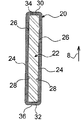
Referring to FIG. 1, a
図1からわかるように、貯蔵装置1は、平行に配置された複数の隣接したハウジング2を有し、これらはそれぞれ、長手方向軸4に沿って延びている。ハウジング2はそれぞれ、断面が正方形である少なくとも1つの核燃料集合体、より好ましくは単一の核燃料集合体を受け入れることができる。
As can be seen from FIG. 1, the
したがって、ハウジング2は、1つがその他のものに対して並置するように設けられている。それらは、複数のスロット付き構造アセンブリ6a、6bによって構成され、これらの構造アセンブリ6a、6bは、図1に矢印8で概略的に示されるように、ハウジング2の長手方向軸4に平行である積み重ね方向に従って積み重ねられている。より正確に言うと、積み重ね方向8は、貯蔵装置の底部から貯蔵装置の(図示しない)閉鎖板に向かって延びている。慣習的に、本明細書の残りの部分では、「高さ」という概念は、貯蔵装置1の(図示しない)長手方向軸にも平行である積み重ね方向8に関連付けられるべきであることが認められる。
Accordingly, the
この同じ図1でわかるように、スロット付き構造アセンブリ6a、6bは、より好ましくは垂直に交差される。言い換えると、構造アセンブリ6aは互いに対して平行である一方、構造アセンブリ6bも互いに対して平行であるが、構造アセンブリ6bは構造アセンブリ6aに対して垂直をなす。
As can be seen in this same FIG. 1, the slotted
構造アセンブリ6a、6bを積み重ね方向8に従って積み重ねる時、構造アセンブリ6a、6bは協働してハウジング2の各々の側壁を形成し、この側壁は、この第1の好適な実施形態では、ほぼ正方形の横断面を有する。もちろん、ハウジング2の側壁は、六角形のような異なった形の核燃料集合体の保持を可能にする任意の他の形で与えることもできるであろう。
When the
したがって、ハウジング2が正方形の横断面を有する図1に示される例では、構造アセンブリ6aは、方向10と積み重ね方向8とに平行な垂直仕切り9を形成する一方、構造アセンブリ6bは、方向12と積み重ね方向8とに平行な垂直仕切り11を形成する。方向8と、方向10と、方向12とは互いに垂直である。
Thus, in the example shown in FIG. 1 in which the
好ましくは、構造アセンブリ6a、6bの各々は、2つの周囲壁14の間を延びてそれらと一体化しており、これらの周囲壁14により、貯蔵装置1の側方を閉鎖することができる。たとえば、限定的ではないが図示されるように、これらの周囲壁14を4つ設けることができ、各々が貯蔵装置1の全高さにわたって延びて、貯蔵装置1のハウジング2の側壁の周囲部分を構成する。さらに代替的には、本発明の範囲から逸脱することなく、各周囲壁14を、方向8に従って積み重ねられた垂直仕切りの複数の部分によって構成することができる。
Preferably, each of the
さらに、垂直仕切り9、11の各々が、当該積み重ねられた垂直仕切りのいずれかの側に配置された幾つかのハウジング2の側壁の一部分の形成に関与することに注意されたい。
Furthermore, it should be noted that each of the
より詳細に後述するように、スロット付き構造アセンブリ6a、6bの各々は、第2の材料からなる管状断面要素を使用して設計され、管状断面要素には、第1の材料からなる少なくとも1枚の板が内部に収容されている。第1の材料は、ニュートロファージ元素を有するものがより好ましく、したがって、特に、アルミニウム及びホウ素の合金の形態をとるが、当業者であれば、たとえばガドリニウム、ハフニウム、カドミウム、インジウム、サマリウム、ユーロピウムのような他のニュートロファージ元素を採用することもできるであろう。しかしながら、他のアルミニウムをベースとする材料、たとえばアルミニウム合金及び炭化ホウ素を有するマトリックスから構成される複合材料等もまた、この第1の材料を構成すると考えられる。さらに、管状断面要素を構成する第2の材料は、ステンレス鋼のような鋼であることがより好ましいが、それが達成できる機械抵抗についての性能が高いためチタン又はその合金を使用することも考えられる。
As will be described in more detail below, each of the slotted
そのため、図1をさらに参照すると、鋼製の管状断面要素の2つの横側面部の各々は、積み重ね方向8と共に方向10及び12の一方にも平行であって、複数のハウジング2の画定に関与することが簡単にわかる。
Thus, with further reference to FIG. 1, each of the two lateral sides of the steel tubular cross-sectional element is parallel to one of the
次に図2を参照すると、積み重ねられた垂直仕切り9、11及び周囲壁14によって側壁が形成されているハウジング2はそれぞれ、正方形の断面を有する側面174によって内部が画定されることがわかる。この側面174は、積み重ねられた垂直仕切り9、11をそれぞれ形成する構造アセンブリ6a、6bの鋼製の管状断面要素の横側面部によって少なくとも部分的に構成することができる。
Referring now to FIG. 2, it can be seen that the
図2に明確に示されるように、この場合には、これらのハウジング2の各々の側面の一部分もまた周囲壁14を使用して形成されるため、ハウジング2の側面174だけは、横側面部によって完全に構成されるわけではない。
As clearly shown in FIG. 2, in this case only a side 174 of the
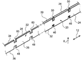
次に図4を参照すると、本発明の第1の好適な実施形態による貯蔵装置1の一部分を見ることができ、この貯蔵装置1は、図3a〜図3cに示されるようなスロット付き構造アセンブリ6a、6bの積み重ね体を使用して構成されている。そのため、垂直仕切り9を構成する構造アセンブリ6aは、垂直仕切り11を構成する構造アセンブリ6bと同一又は同様であり、そのうちの1つを、図3a〜図3cを参照しながら以下に説明する。
Referring now to FIG. 4, a portion of a
本発明の第1の好適な実施形態では、スロット付き構造アセンブリ6bは、ステンレス鋼製の管状断面要素20から構成され、その内部に、アルミニウム又はホウ素の合金の板22が配置されている。図3cに最もわかりやすく示されるように、板22は、管状断面要素20によって内部に画定される形状に対して相補的である略矩形の形状を有し、したがって、ほぼ矩形の横断面も有している。
In the first preferred embodiment of the present invention, the slotted
第1の好適な実施形態では、単一の板22は実際上、管状断面要素20の2つの横側面部24間を摺動するように設けられている。そのため、板22の2つの外側面26はそれぞれ、管状断面要素20の横側面部24の内部側面28と面接触状態にあるが、取り付け及び伸長差に対処するために、作業隙間が設けられている。
In the first preferred embodiment, a
さらに、管状断面要素20は、2つの横側面部24によって連結されている上縁部30及び下縁部32間を延び、したがって、板22はまた、上縁部30及び下縁部32間を摺動する。言い換えると、板22の上縁部34及び下縁部36はそれぞれ、管状断面要素20の上縁部30及び下縁部32と面接触状態にあるが、摺動によって一方を他方の内部に取り付けることを可能にするために、及び使用する材料の個々の特性に起因して見られる伸長差に対処するために、作業隙間が設けられている。
Furthermore, the tubular
したがって、構造アセンブリは、板22の方向8の高さが管状断面要素20の内側の高さにほぼ等しいことにより、構造アセンブリが協働して、貯蔵装置の全長にわたってほぼ連続的に延びる高熱伝導性の中性子物質の構造体を形成するように構成されることがより好ましい。
Thus, the structural assembly is such that the height in the direction 8 of the
中性子物質の単一の板22が管状断面要素20によって画定される内部空間のほぼ全体を占めるこの第1の好適な実施形態は、特に、BWRタイプの燃料集合体用の貯蔵装置の構成用である。
This first preferred embodiment, in which a
図3aに示されるように、構造アセンブリ6bは、上側スロット40が設けられた上側部分及び下側スロット42が設けられた下側部分を有し、上側スロット40は、方向8において下側スロット42より低い高さを有するという特殊性を有している。
As shown in FIG. 3 a, the
この点において、構造アセンブリは、上側スロット40及びその対向位置に配置された下側スロット42の高さの合計が、構造アセンブリ6bの高さのほぼ半分に等しいことにより、構造アセンブリ6a、6bを積み重ねて交差させた後、ほぼ連続した側壁が得られるように構成することがより好ましい。
In this respect, the structural assembly is structured such that the sum of the heights of the
下側スロット42の各々は、管状断面要素20の全厚にわたって形成されたノッチ46と、単一の板22の全厚にわたって形成されたほぼ同一の高さのノッチ48とを使用して構成される。
Each of the
したがって、好ましくはノッチ48をすでに備えている板22を、好ましくは同様にノッチ46をすでに備えている管状断面要素20の内部で摺動させる時、構造アセンブリ6bの下側スロット42を形成するために、これらのノッチ46、48は2つずつ合致する。参考までに、さらに図3aからわかるように、アルミニウムをベースにした第1の材料内に形成されるノッチ48は、ステンレス鋼からなる第2の材料内に形成されるノッチ46よりも、方向12において、特に相当に幅広であることが定められている。この幅の差により、方向12における構造アセンブリ6bの第1の材料及び第2の材料間の伸長差にうまく対処することが可能である。
Thus, preferably when the
一方、上側スロット40はそれぞれ、鋼製の管状断面要素20の上縁部30上に形成された単一のノッチ50を使用するだけで構成され、板22の上縁部34はノッチを有さず、このために、構造アセンブリ6bの全長にわたって一定の断面を有する。
On the other hand, each of the
上述したように、積み重ね方向8において下側スロット42が上側スロット40より大きいこの構造は、方向8の垂直自由落下の場合に貯蔵装置の機械的剛性を強化するために設けられる。実際上、そのような垂直自由落下に続く衝突中、後述するように、端部で並進が停止した管状断面要素20は曲げを受けて、緩やかな曲線が方向8に、すなわち、その時に底部の方に向いている容器の上側部分に向けて描かれる。したがって、この曲げにより、ノッチ46が閉じて、より小さい寸法のノッチ50が開く。管状断面要素20が、交差部分で特に高度に調整されているとすると、再閉鎖中のノッチ46が、交差した管状断面要素20と接触するように満たす必要のある隙間が大幅に減少する。したがって、曲げが生じた時、再閉鎖中のノッチ46は、対応する下側スロット42内に収容されている管状断面要素20と迅速に接触し、したがって、交差区域内の剛直性(stiffness)を相当に増加させる。
As described above, this structure in which the
複数の構造アセンブリ6a、6bを積み重ねると共に交差させた図4において、互いに平行な構造アセンブリ6aの第(n+1)層の存在が、まず最初に確認される。さらに、第(n+2)層は、積み重ね方向8において第(n+1)層のすぐ上に配置され、この目的で設けられる上側スロット40及び下側スロット42によって第(n+1)層の構造アセンブリ6aと協働する構造アセンブリ6bから構成される。そのため、第(n+2)層の構造アセンブリ6b及び第(n+1)層の構造アセンブリ6aは、積み重ね方向8において直接的に連続状に配置され、且つ互いに交差状に配置される。
In FIG. 4, where a plurality of
最後に、第(n+3)層は、積み重ね方向8において第(n+2)層のすぐ上に配置されて、上側スロット40及び下側スロット42によって第(n+2)層の構造アセンブリ6bと協働する構造アセンブリ6aから構成される。したがって、第(n+2)層の構造アセンブリ6b及び第(n+3)層の構造アセンブリ6aは、積み重ね方向8において直接的に連続状に配置され、且つ互いに交差状に配置される。さらに、図4からわかるように、第(n+1)層及び第(n+3)層の構造アセンブリ6aは、管状断面要素20の上縁部30及び下縁部32上で2つずつ互いに非常に近接しているか、又は接触している。
Finally, the (n + 3) th layer is arranged immediately above the (n + 2) th layer in the stacking direction 8 and cooperates with the
より一般的には、より低い高さの各上側スロット40が、隣接する構造アセンブリの下側スロット42と協働するように、またその逆に協働するように意図されることが示されている。
More generally, it is shown that each lower height
次に図5a〜図5bを参照すると、この第1の好適な実施形態の代替例であって、たった今上記したばかりのものに概ね似ている設計の代替例を示すことができる。そのため、全図面で、同じ参照符号を付けた構成要素は、同一又は同様の構成要素に対応する。 Referring now to FIGS. 5a-5b, an alternative to this first preferred embodiment can be shown in an design that is generally similar to that just described. Therefore, in all the drawings, the components given the same reference numerals correspond to the same or similar components.
そのため、この代替例において、主な変更は、上側スロット40及び下側スロット42が方向8において同一の高さを有し、それらの高さの合計がやはり構造アセンブリ6bの高さの半分にほぼ等しいように設けられるという事実にあることがわかるであろう。
Thus, in this alternative, the main change is that the
そのために、各上側スロット40が、もはや管状断面要素20の上縁部30上の単一のノッチ50だけを使用して構成され得るのではなく、図5aに示されるように、この同じノッチ50と合致する、板22の上縁部34上に設けられる上側ノッチ60も使用して得られる。したがって、この代替例では、上側スロット40及び下側スロット42を同様にして得ることができる。
To that end, each
さらに、限定することはないが、現断面におけるこの構造アセンブリの横断面は、図3cに示されるものと同一である。 Further, but not limited to, the cross section of this structural assembly in the current cross section is identical to that shown in FIG. 3c.
図6a及び図6bに示される第2の好適な実施形態では、構造アセンブリ6a、6bは、上記代替例で説明したものとほぼ同様の上側スロット40及び下側スロット42の構成を有するが、代替として、図3a〜図3cに示されるようなタイプであってもよい。したがって、第2の好適な実施形態は、対応する管状断面要素20によって画定された空間のほぼ全体を占める第1の材料から成る単一の板ではなく、互いに離隔する2枚の個別の板22を組み込んでいることで、第1の好適な実施形態と区別される。
In a second preferred embodiment shown in FIGS. 6a and 6b, the
より正確に言うと、2枚の板22の間の空間により、貯蔵装置に核燃料集合体を装填した時、貯蔵装置の準臨界を維持する目的で、水を満たすのに適した空間64を画定することができる。したがって、この第2の実施形態は、特にPWR(加圧水型軽水炉)タイプの核燃料集合体用の貯蔵装置の構成用である。
More precisely, the space between the two
図6bで最もよくわかるように、2枚の同一の板22の各々は、それらを収容している鋼製の管状断面要素20の上縁部30及び下縁部32の間を摺動するように設けられている。さらに、2枚の同一の板22の各々は、管状断面要素20の横側面部24の2つの内部側面28にそれぞれ面する外側面26を有し、取り付けを可能にすると共に伸長差に対処するために、作業隙間が設けられている。2枚の板22のうち、外側面26と反対の内側面66は互いに向き合って、鋼製の管状断面要素20の上縁部30及び下縁部32と協働して、水を満たすことのできる空間64を画定する。
As best seen in FIG. 6b, each of the two
ここでもまた、2枚の板22の各々の厚さは管状断面要素20の厚さより大幅に小さいが、方向8におけるこれらの板22の各々の高さは、やはり管状断面要素20の内側の高さとほぼ同一である。
Again, the thickness of each of the two
図6aに示されるように、各上側スロット40は、2枚の板22の上縁部34にそれぞれ形成された2つの上側ノッチ60と共に、管状断面要素20の上縁部30に形成された上側ノッチ50によっても形成され、これらの上側ノッチ50、60、60はもちろん、互いに合致している。同様に、各下側スロット42は、2枚の板22の下縁部36にそれぞれ形成された2つの下側ノッチ48と共に、管状断面要素20の下縁部32に形成された下側ノッチ46によっても形成され、これらの下側ノッチ46、48、48は互いに合致している。
As shown in FIG. 6 a, each
最後になるが、2枚の板22のスペーサ68、たとえば方向8に平行なロッドの形をしたスペーサ68を、貯蔵装置1の上側スロット40及び下側スロット42上に置くことができることが示されている。したがって、貯蔵装置1は、スペーサ68の直径及び2枚の板22の厚さの合計が、管状断面要素20の2つの横側面部24間の内側の間隔とほぼ同一であるように構成されている。
Finally, it is shown that the
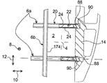
図7を参照すると、一般的にケーシング72を含む容器70が示され、ケーシングの内部には、上記したばかりのものの1つ等であって、ケーシング内に入れられるように設けられる貯蔵装置1が見られ、図7にはこの貯蔵装置1が概略的に示されているだけである。
Referring to FIG. 7, there is shown generally a
当業者には既知のように、積み重ね方向8に平行な長手方向軸73のケーシング72は、貯蔵装置1が載置されるベース74と、このケーシングを閉鎖すると共に貯蔵装置1の上端部78から離して配置された蓋76とを有する。それはまた、貯蔵装置1の長手方向軸と合体された長手方向軸73の周囲に延びる側面胴部80を有する。
As known to those skilled in the art, the
さらに好ましくは、貯蔵装置1は、側面胴部80に対する方向8への長手方向軸73に沿った並進が蓋76から離れた位置でロックされる。そのため、これにより、この蓋76が底部の方に向いた状態での垂直自由落下であって、この蓋76に設けられるケーシング70のシールの破壊を生じやすい垂直自由落下中に、貯蔵装置1が蓋76と衝突することを回避することができる。
More preferably, the
蓋76から離れた位置で貯蔵装置1の並進をこのようにロックするために、側面胴部80の上側部分内に収容されると共にケーシングの内部に向かって半径方向に突出するストップ要素82の形態をとるストップ手段が設けられている。図7でわかるように、貯蔵装置1の上端部78は、自由落下中に支持体としてこれらのストップ要素82にぶつかる。より正確に言うと、貯蔵装置1は、ストップ要素82が、構造アセンブリの積み重ね体の周囲に配置された貯蔵装置の周囲壁とだけ協働するように配置されている。
In order to thus lock the translation of the
さらに、図1、図8a及び図8bを参照すると、構造アセンブリ6a、6bを周囲壁14に取り付けるための好適な実施形態の一例を見ることができる。
Further, referring to FIGS. 1, 8a and 8b, an example of a preferred embodiment for attaching the
一般的に貯蔵装置1は、各構造アセンブリ6a、6bが、2つの対向する端部を有し、該対向する端部の各々は、図8aでわかるように、同じ側壁の任意の2つの直接的に連続した構造アセンブリ6a、6b間に隙間86が存在するように、周囲壁14に取り付けられている。
In general, the
そのために、各構造アセンブリの端部は、トリップドッグ(trip dog)と呼ばれる組み付け部品88を備え、組み付け部品88は、たとえばねじ付けによって組み付け部品88を取り付ける板22と接触するまで、管状断面要素20の内部に貫入される。組み付け部品88の、構造アセンブリの外に突出する部分は、周囲壁14の内側に形成された長手方向チャネル90内に収容され、したがって、方向8での組み付け部品88の高さは、これらの組み付け部品が長手方向チャネル90内で互いに接触している時、図8aで最もよくわかるように、隙間86が管状断面要素20間に現れるようにして与えられる。
To that end, the end of each structural assembly is provided with an
得られる隙間86により、構造アセンブリの各々の保持を切り離すことができ、したがって、構造アセンブリは、互いに独立的に周囲壁14上に保持される。その場合、軸方向落下での貯蔵装置1全体の機械的強度の証明は、この貯蔵装置1の構造アセンブリの任意の1つの機械的強度の簡単な証明によって行うことができる。
The resulting
限定的ではないが、各長手方向チャネル90はストップ92を有し、2つの直接的に連続したストップ92間に配置された一連の組み付け部品88が、容器の垂直自由落下中に支持体として各ストップの上に載りやすいようにすることができる。これにより、組み付け部品88を移動させる圧縮応力を許容値に制限することが可能である。
Without limitation, each
もちろん、当業者であれば、限定的ではなく例示としてのみ上記した貯蔵装置1及び容器に対してさまざまな修正を加えることができる。
Of course, those skilled in the art can make various modifications to the
1 貯蔵装置、2 ハウジング、6a,6b 構造アセンブリ、14 周囲壁、20 管状断面要素、22 板、24 横側面部、28 内部側面、30 (管状断面要素20の)上縁部、32 (管状断面要素20の)下縁部、40 上側スロット、42 下側スロット、46,48,50,60 ノッチ、70 容器、72 ケーシング、73 (ケーシング72の)長手方向軸、74 ベース、76 蓋、80 側面胴部、82 ストップ手段、86 隙間、174 側面。
DESCRIPTION OF
Claims (21)
前記各構造アセンブリ(6a、6b)は、管状断面要素(20)をさらに有し、該管状断面要素(20)の内部に前記少なくとも1枚の板(22)が位置し、前記管状断面要素(20)は、鋼とチタンとその合金とから選択される第2の材料からなることを特徴とする貯蔵装置。 A storage device (1) for storing and / or transporting nuclear fuel assemblies, comprising a plurality of adjacent housings (2), each housing (2) having side walls and said nuclear fuel assemblies. And the sidewalls comprise at least a portion using stacked and crossed slotted structural assemblies (6a, 6b), each structural assembly (6a, 6b) comprising a first material comprising aluminum. In a storage device (1) having at least one plate (22) consisting of
Each structural assembly (6a, 6b) further comprises a tubular cross-sectional element (20), in which the at least one plate (22) is located, the tubular cross-sectional element (20) 20) is a storage device characterized by comprising a second material selected from steel, titanium and alloys thereof.
前記上側スロット(40)の各々は、前記管状断面要素(20)内に形成されたノッチ(50)だけを使用して構成されることを特徴とする、請求項13に記載の貯蔵装置。 Each of the lower slots (42) uses a notch (46) formed in the tubular cross-sectional element (20) and a notch (48) formed in each plate (22) of the structural assembly. Configured,
14. Storage device according to claim 13, characterized in that each of the upper slots (40) is constructed using only notches (50) formed in the tubular cross-sectional element (20).
請求項1〜18のいずれか一項に記載の前記貯蔵装置(1)を内部に収容したケーシング(72)を含むことを特徴とする容器。 A container (70) for storage and / or transportation of nuclear fuel assemblies, comprising:
A container comprising a casing (72) containing therein the storage device (1) according to any one of claims 1-18.
ベース(74)と、
蓋(76)と、
前記貯蔵装置の長手方向軸と合体するケーシングの長手方向軸(73)の周囲に延びる側面胴部(80)と
を有し、
前記貯蔵装置は、前記蓋(76)から離れた位置で、該蓋(76)の方向での前記ケーシングの前記長手方向軸(73)に沿った前記側面胴部(80)に対する並進がロックされることを特徴とする、請求項19に記載の容器。 The casing (72)
A base (74);
A lid (76);
A side barrel (80) extending around the longitudinal axis (73) of the casing that merges with the longitudinal axis of the storage device;
The storage device is locked for translation relative to the side barrel (80) along the longitudinal axis (73) of the casing in the direction of the lid (76) at a position remote from the lid (76). The container according to claim 19, wherein
Applications Claiming Priority (1)
| Application Number | Priority Date | Filing Date | Title |
|---|---|---|---|
| FR0655110A FR2909216B1 (en) | 2006-11-27 | 2006-11-27 | STORAGE DEVICE FOR STORING AND / OR TRANSPORTING NUCLEAR FUEL ASSEMBLIES |
Related Child Applications (1)
| Application Number | Title | Priority Date | Filing Date |
|---|---|---|---|
| JP2013089174A Division JP5635643B2 (en) | 2006-11-27 | 2013-04-22 | Storage device and container for storage and / or transportation of nuclear fuel assemblies |
Publications (1)
| Publication Number | Publication Date |
|---|---|
| JP2008134247A true JP2008134247A (en) | 2008-06-12 |
Family
ID=38171591
Family Applications (2)
| Application Number | Title | Priority Date | Filing Date |
|---|---|---|---|
| JP2007295156A Pending JP2008134247A (en) | 2006-11-27 | 2007-11-14 | Storage device and container for storing and/or transporting nuclear fuel assembly |
| JP2013089174A Active JP5635643B2 (en) | 2006-11-27 | 2013-04-22 | Storage device and container for storage and / or transportation of nuclear fuel assemblies |
Family Applications After (1)
| Application Number | Title | Priority Date | Filing Date |
|---|---|---|---|
| JP2013089174A Active JP5635643B2 (en) | 2006-11-27 | 2013-04-22 | Storage device and container for storage and / or transportation of nuclear fuel assemblies |
Country Status (6)
| Country | Link |
|---|---|
| US (1) | US7961834B2 (en) |
| EP (1) | EP1926107B1 (en) |
| JP (2) | JP2008134247A (en) |
| AT (1) | ATE472805T1 (en) |
| DE (1) | DE602007007423D1 (en) |
| FR (1) | FR2909216B1 (en) |
Cited By (2)
| Publication number | Priority date | Publication date | Assignee | Title |
|---|---|---|---|---|
| JP2013181798A (en) * | 2012-03-01 | 2013-09-12 | Hitachi-Ge Nuclear Energy Ltd | Cask |
| JP2015509197A (en) * | 2012-01-19 | 2015-03-26 | アレバ インコーポレイテッド | System for storage and transfer of spent nuclear fuel |
Families Citing this family (5)
| Publication number | Priority date | Publication date | Assignee | Title |
|---|---|---|---|---|
| JP5010491B2 (en) * | 2008-01-30 | 2012-08-29 | 三菱重工業株式会社 | Recycled fuel assembly storage basket, recycled fuel assembly storage container, and method for manufacturing recycled fuel assembly storage basket |
| FR3041141B1 (en) * | 2015-09-11 | 2017-10-13 | Tn Int | IMPROVED STORAGE DEVICE FOR STORING AND / OR TRANSPORTING NUCLEAR FUEL ASSEMBLIES |
| FR3044819B1 (en) * | 2015-12-03 | 2017-12-22 | Tn Int | STORAGE DEVICE FOR STORING AND / OR TRANSPORTING NUCLEAR FUEL ASSEMBLIES, COMPRISING STAGES WITH DIFFERENTIATED FUNCTIONS |
| TWI795484B (en) | 2017-12-20 | 2023-03-11 | 美商Tn美國有限責任公司 | Modular basket assembly for fuel assemblies |
| CN114846563A (en) | 2019-12-09 | 2022-08-02 | 霍尔泰克国际公司 | Nuclear fuel storage system with integral gasket |
Citations (7)
| Publication number | Priority date | Publication date | Assignee | Title |
|---|---|---|---|---|
| JPS6166194A (en) * | 1984-09-04 | 1986-04-04 | ウエスチングハウス エレクトリック コーポレーション | Storage cask for spent fuel |
| JPH0210200A (en) * | 1988-02-19 | 1990-01-12 | Transnucleaire Sa | Nuclear fuel element packed rack |
| US4896046A (en) * | 1988-05-24 | 1990-01-23 | Westinghouse Electric Corp. | Fuel rod shipping cask having peripheral fins |
| JP2001083287A (en) * | 1999-09-09 | 2001-03-30 | Mitsubishi Heavy Ind Ltd | Aluminum composite material and its production method, basket and cask thereof |
| JP2002221591A (en) * | 2001-01-25 | 2002-08-09 | Mitsubishi Heavy Ind Ltd | Cask, and method of manufacturing cask |
| JP2002250790A (en) * | 2001-02-26 | 2002-09-06 | Mitsubishi Heavy Ind Ltd | Cask |
| WO2006005891A1 (en) * | 2004-07-08 | 2006-01-19 | Tn International | Storage device for storing and transposing nuclear fuel assemblies |
Family Cites Families (6)
| Publication number | Priority date | Publication date | Assignee | Title |
|---|---|---|---|---|
| US4781883A (en) * | 1984-09-04 | 1988-11-01 | Westinghouse Electric Corp. | Spent fuel storage cask having continuous grid basket assembly |
| FR2650113B2 (en) * | 1988-02-19 | 1992-04-03 | Transnucleaire | IMPROVEMENT IN A NUCLEAR FUEL STORAGE BOX |
| DE59603679D1 (en) * | 1995-05-24 | 1999-12-23 | Siemens Ag | ABSORPTION STRUCTURE FOR ABSORPTION OF NEUTRON AND METHOD FOR PRODUCING AN ABSORPTION STRUCTURE |
| ES2205974B1 (en) * | 2001-05-24 | 2005-05-01 | Equipos Nucleares, S.A. | SEGMENTED FRAME OF INTERRELATED CELLULAR MATRIX, TO STORE FUELS FROM NUCLEAR REACTORS. |
| JP3981642B2 (en) * | 2003-03-06 | 2007-09-26 | 三井造船株式会社 | Dry cask |
| JP2007171135A (en) * | 2005-12-26 | 2007-07-05 | Hitachi Ltd | Cask for spent fuel |
-
2006
- 2006-11-27 FR FR0655110A patent/FR2909216B1/en not_active Expired - Fee Related
-
2007
- 2007-11-14 JP JP2007295156A patent/JP2008134247A/en active Pending
- 2007-11-23 EP EP07121439A patent/EP1926107B1/en active Active
- 2007-11-23 AT AT07121439T patent/ATE472805T1/en not_active IP Right Cessation
- 2007-11-23 DE DE602007007423T patent/DE602007007423D1/en active Active
- 2007-11-27 US US11/998,109 patent/US7961834B2/en active Active
-
2013
- 2013-04-22 JP JP2013089174A patent/JP5635643B2/en active Active
Patent Citations (8)
| Publication number | Priority date | Publication date | Assignee | Title |
|---|---|---|---|---|
| JPS6166194A (en) * | 1984-09-04 | 1986-04-04 | ウエスチングハウス エレクトリック コーポレーション | Storage cask for spent fuel |
| JPH0210200A (en) * | 1988-02-19 | 1990-01-12 | Transnucleaire Sa | Nuclear fuel element packed rack |
| US4896046A (en) * | 1988-05-24 | 1990-01-23 | Westinghouse Electric Corp. | Fuel rod shipping cask having peripheral fins |
| JP2001083287A (en) * | 1999-09-09 | 2001-03-30 | Mitsubishi Heavy Ind Ltd | Aluminum composite material and its production method, basket and cask thereof |
| JP2002221591A (en) * | 2001-01-25 | 2002-08-09 | Mitsubishi Heavy Ind Ltd | Cask, and method of manufacturing cask |
| JP2002250790A (en) * | 2001-02-26 | 2002-09-06 | Mitsubishi Heavy Ind Ltd | Cask |
| WO2006005891A1 (en) * | 2004-07-08 | 2006-01-19 | Tn International | Storage device for storing and transposing nuclear fuel assemblies |
| JP2008506101A (en) * | 2004-07-08 | 2008-02-28 | テーエヌ・アンテルナシオナル | Storage device for storing and transporting nuclear fuel assemblies |
Cited By (2)
| Publication number | Priority date | Publication date | Assignee | Title |
|---|---|---|---|---|
| JP2015509197A (en) * | 2012-01-19 | 2015-03-26 | アレバ インコーポレイテッド | System for storage and transfer of spent nuclear fuel |
| JP2013181798A (en) * | 2012-03-01 | 2013-09-12 | Hitachi-Ge Nuclear Energy Ltd | Cask |
Also Published As
| Publication number | Publication date |
|---|---|
| FR2909216A1 (en) | 2008-05-30 |
| US20080123798A1 (en) | 2008-05-29 |
| EP1926107B1 (en) | 2010-06-30 |
| JP2013174603A (en) | 2013-09-05 |
| FR2909216B1 (en) | 2009-02-20 |
| EP1926107A1 (en) | 2008-05-28 |
| ATE472805T1 (en) | 2010-07-15 |
| DE602007007423D1 (en) | 2010-08-12 |
| US7961834B2 (en) | 2011-06-14 |
| JP5635643B2 (en) | 2014-12-03 |
Similar Documents
| Publication | Publication Date | Title |
|---|---|---|
| JP5635643B2 (en) | Storage device and container for storage and / or transportation of nuclear fuel assemblies | |
| ES2401747T3 (en) | Packaging sets and internal support structure for the transport and storage of radioactive materials | |
| US20110051883A1 (en) | Rack systems and assemblies for fuel storage | |
| US9685248B2 (en) | Snap-in insert for reactivity control in spent nuclear fuel pools and casks | |
| US20180122527A1 (en) | Fuel basket for spent nuclear fuel and container implementing the same | |
| JP2006349469A (en) | Used fuel storage basket, and used fuel storage container | |
| KR100315869B1 (en) | Nuclear Fuel Assembly Rack | |
| JP6800218B2 (en) | Improved storage equipment for storing and / or transporting nuclear fuel assemblies | |
| KR20220107066A (en) | Nuclear fuel storage system with integral seaming | |
| WO2014010386A1 (en) | Basket and cask | |
| JP2006200939A (en) | Spent fuel container basket and spent fuel storage vessel | |
| JP2019158398A (en) | Spent fuel storage container | |
| JP4398929B2 (en) | Spent fuel storage container | |
| JP4727229B2 (en) | Containers for storage / transport of unirradiated radioactive material such as nuclear fuel assemblies | |
| JP2011089960A (en) | Method for packing nuclear fuel rod packing body, nuclear fuel rod packing body skeleton, nuclear fuel rod packing body holding plate, and nuclear fuel rod into transport | |
| JP2019158399A (en) | Spent fuel storage container | |
| JP5627538B2 (en) | Nuclear fuel pellet transport container | |
| JP2013181798A (en) | Cask | |
| JP2020085585A (en) | Spent fuel storage container | |
| JP7195214B2 (en) | Spent fuel container | |
| JP5787813B2 (en) | Radioactive material containment vessel | |
| US11450444B2 (en) | Storage basket for radioactive materials, having an optimised space requirement and housings with more accurate geometry | |
| JP2020134327A (en) | Nuclear fuel storage rack, method for setting nuclear fuel storage rack, and method for manufacturing nuclear fuel storage rack | |
| JP2015004577A (en) | Radioactive substance storage basket and radioactive substance storage container | |
| JP2006105741A (en) | Radioactive material storage vessel |
Legal Events
| Date | Code | Title | Description |
|---|---|---|---|
| A621 | Written request for application examination |
Free format text: JAPANESE INTERMEDIATE CODE: A621 Effective date: 20101101 |
|
| A131 | Notification of reasons for refusal |
Free format text: JAPANESE INTERMEDIATE CODE: A131 Effective date: 20130122 |
|
| A02 | Decision of refusal |
Free format text: JAPANESE INTERMEDIATE CODE: A02 Effective date: 20130702 |