JP2008123797A - Contactless switch - Google Patents
Contactless switch Download PDFInfo
- Publication number
- JP2008123797A JP2008123797A JP2006305411A JP2006305411A JP2008123797A JP 2008123797 A JP2008123797 A JP 2008123797A JP 2006305411 A JP2006305411 A JP 2006305411A JP 2006305411 A JP2006305411 A JP 2006305411A JP 2008123797 A JP2008123797 A JP 2008123797A
- Authority
- JP
- Japan
- Prior art keywords
- lens
- light
- amount
- light receiving
- emitting element
- Prior art date
- Legal status (The legal status is an assumption and is not a legal conclusion. Google has not performed a legal analysis and makes no representation as to the accuracy of the status listed.)
- Pending
Links
Images


Abstract
Description
本発明は、光を利用した無接点スイッチに関するものである。 The present invention relates to a contactless switch using light.
ノブの操作に連動して、可動接点を固定接点に対して摺動させて接離させることにより、電気回路を開閉して、ノブの位置を検出するスイッチがある。このような機械的接点を有するスイッチでは、接点が摩耗や酸化等により接触不良になることが懸念される。また、接点には機械的な寿命があって、該寿命は比較的短い。さらに、ノブと接点とが連動しているため、接点の摺動抵抗等に妨害されて、ノブ等の移動体の理想的なF−S(Force−Stroke;操作荷重−変位)特性が得られない。 In conjunction with the operation of the knob, there is a switch that detects the position of the knob by opening and closing an electric circuit by sliding the movable contact with respect to the fixed contact. In a switch having such a mechanical contact, there is a concern that the contact may become defective due to wear or oxidation. Further, the contact has a mechanical life, and the life is relatively short. Furthermore, since the knob and the contact point are interlocked, it is obstructed by the sliding resistance of the contact point and the ideal FS (Force-Stroke) characteristic of the moving body such as the knob is obtained. Absent.
一方、下記の特許文献1〜5には、光を利用した無接点スイッチが開示されている。特許文献1では、可動体の操作に連動して、レンズを発光素子と受光素子との間で光軸方向へ移動させて、受光素子の受光量を変化させ、該受光量が所定のレベルにおいてスイッチ出力を発生させて、可動体の位置を検出している。特許文献2では、肉厚が軸方向に変化するパイプ状のレンズ効果を有する光透過体を、直線移動体の操作に連動して、発光素子と受光素子との間で光軸に対して垂直な方向に移動させて、受光素子の受光量を変化させ、該受光量に応じた受光素子からの出力信号より直線移動体の位置を検出している。特許文献3では、透光窓と遮光窓とが設けられたシャッタを、キートップの操作に連動して、2つのフォトインタラプタの凹部内で光軸に対して垂直に5つの位置へ移動させて、各フォトインタラプタの光を透過しまたは遮断し、5種類のモードの信号を出力している。
On the other hand, the following Patent Documents 1 to 5 disclose contactless switches using light. In Patent Document 1, in conjunction with the operation of the movable body, the lens is moved between the light emitting element and the light receiving element in the optical axis direction to change the amount of light received by the light receiving element. A switch output is generated to detect the position of the movable body. In
特許文献4では、光ファイバから成る1本の出射光路の入射側を発光素子に対向させ、光ファイバから成る2本の入射光の各入射側を出射光路の出射側に対向させ、該入射光路の各出射側を2つの受光素子に対向させ、両受光素子の出力差を検出する作動増幅器および比較器を設けている。そして、作動部材の操作に連動して、出射光路または入射光路の一方の端部を入射光路の配列方向へ変位させて、両受光素子の出力差を変化させ、該出力差の極性または絶対値よりスイッチのオン・オフを判別している。特許文献5では、複数の平行な孔または逆三角形の孔が設けられた片状体を、ボタンの操作に連動して、発光素子と受光素子との間で光軸に対して垂直な方向へ移動させて、受光素子の受光量を変化させ、該受光量に応じた受光素子からの出力信号より、ボタンの操作を検出している。
In
特許文献1、2、5のような構造では、発光素子の特性のばらつきや、温度等の環境変化や、経時変化等により、発光素子の発光量が変動した場合、これに伴って受光素子の受光量も変動するため、該受光量から移動体の位置を正確に検出できなくなる。特許文献3のような構造では、キートップとシャッタの各移動位置で、各フォトインタラプタの光を正確に透過しまたは遮断するように、キートップとシャッタとフォトインタラプタ等の寸法や組み立ての精度を厳しくしなければならず、スイッチの製造が困難である。特許文献4のような構造では、発光素子と受光素子の間に出射光路と入射光路となる光ファイバを設けているため、部品点数が多くて、スイッチの製造が困難であり、発光素子と受光素子の間隔が広くて、スイッチが大型化する。
In structures such as
本発明は、上記問題点を解決するものであって、その課題とするところは、発光素子の特性のばらつきや環境変化や経時変化に強健(ロバスト)で、かつ製造が容易で、かつ小型化できる無接点スイッチを提供することにある。 The present invention solves the above-mentioned problems, and the problem is that it is robust against variations in characteristics of light emitting elements, environmental changes, and changes over time, is easy to manufacture, and is downsized. It is to provide a contactless switch that can be used.
本発明に係る無接点スイッチは、光を発生する発光素子と、発光素子からの光を受光する第1の受光素子および第2の受光素子と、発光素子と第1および第2の受光素子の間に設けられたレンズと、発光素子の光軸に対して垂直な方向にレンズを移動させる移動機構と、第1および第2の受光素子の受光量に基づいてレンズが移動した量または方向と量を検出する移動検出手段とを備えている。 The contactless switch according to the present invention includes a light emitting element that generates light, a first light receiving element and a second light receiving element that receive light from the light emitting element, a light emitting element, and the first and second light receiving elements. A lens provided therebetween, a moving mechanism for moving the lens in a direction perpendicular to the optical axis of the light emitting element, and an amount or direction of movement of the lens based on the amount of light received by the first and second light receiving elements Movement detection means for detecting the amount.
このようにすると、発光素子の特性のばらつきや環境変化や経時変化により、発光素子の発光量が変動しても、これに伴う第1および第2の受光素子の受光量の変動量は同等になるので、第1および第2の受光素子の受光量の変化から、移動機構によるレンズの移動量または移動方向と移動量を正確に検出することができる。つまり、発光素子の特性のばらつきや環境変化や経時変化に対して、無接点スイッチを強健にすることが可能となる。このため、レンズの移動量または移動方向と移動量に応じてスイッチ出力を確実に発生することが可能となる。また、発光素子からの光を受光素子で常に受光すればよく、該光をレンズの位置に応じて受光素子に対して透過したり遮断したりする必要がないので、各部品の製造と組み付けの精度をあまり厳しくしなくてもよくなり、無接点スイッチの製造を容易にすることができる。また、発光素子からの光をレンズで各受光素子へ導くので、部品点数が少なく、無接点スイッチの製造を容易にすることができ、発光素子と各受光素子の間隔を狭くして、無接点スイッチを小型化することができる。また、一方の受光素子が故障しても、一方の受光素子の受光量が他方の受光素子の受光量に対して異常となるので、レンズの位置にかかわりなく、該故障を容易に検出することができる。さらに、機械的接点が無いので、接点の接触不良といった不具合が生じず、寿命が長くなり、移動機構とレンズの動作が妨害されず、設計した理想的なレンズ等のF−S特性を実現することができる。 In this way, even if the light emission amount of the light emitting element fluctuates due to variations in the characteristics of the light emitting element, environmental changes, or changes over time, the amount of fluctuation in the light reception amount of the first and second light receiving elements is equal. Therefore, the moving amount or moving direction and moving amount of the lens by the moving mechanism can be accurately detected from the change in the light receiving amount of the first and second light receiving elements. That is, the contactless switch can be made robust against variations in characteristics of light emitting elements, environmental changes, and changes with time. For this reason, it is possible to reliably generate the switch output according to the moving amount or moving direction and moving amount of the lens. In addition, the light from the light emitting element is always received by the light receiving element, and it is not necessary to transmit or block the light to the light receiving element depending on the position of the lens. The accuracy does not have to be so strict, and the production of the contactless switch can be facilitated. In addition, since the light from the light emitting element is guided to each light receiving element by a lens, the number of parts is small, making it easy to manufacture a contactless switch. The switch can be miniaturized. Even if one light receiving element fails, the amount of light received by one light receiving element becomes abnormal with respect to the amount of light received by the other light receiving element, so that the failure can be easily detected regardless of the position of the lens. Can do. Furthermore, since there is no mechanical contact, there is no problem such as contact failure, the life is prolonged, the movement mechanism and the operation of the lens are not hindered, and the FS characteristic of the designed ideal lens or the like is realized. be able to.
また、本発明の一実施形態では、上記無接点スイッチにおいて、第1および第2の受光素子は、レンズの移動方向へ並べて設けられ、移動検出手段は、第1および第2の受光素子の受光量の差分に基づいてレンズが移動した方向と量を検出する。 In one embodiment of the present invention, in the contactless switch, the first and second light receiving elements are provided side by side in the lens moving direction, and the movement detecting means receives the light received by the first and second light receiving elements. The direction and amount of movement of the lens are detected based on the amount difference.
このようにすると、発光素子の特性のばらつきや環境変化や経時変化により、発光素子の発光量が変動しても、第1および第2の受光素子の受光量の差分は変動しないので、第1および第2の受光素子の受光量の差分の変化から、レンズの移動方向と移動量を正確に検出することができる。また、一方の受光素子が故障しても、第1および第2の受光素子の受光量の差分が異常となるので、レンズの位置にかかわりなく、該故障を容易に検出することができる。 In this case, even if the light emission amount of the light emitting element varies due to variations in the characteristics of the light emitting element, environmental changes, or changes over time, the difference in the light reception amount of the first and second light receiving elements does not vary. From the change in the difference in the amount of light received by the second light receiving element, the moving direction and amount of movement of the lens can be accurately detected. Even if one of the light receiving elements fails, the difference in the amount of light received by the first and second light receiving elements becomes abnormal, so that the failure can be easily detected regardless of the position of the lens.
また、本発明の一実施形態では、上記無接点スイッチにおいて、第1および第2の受光素子に代えて、発光素子からの光を受光する位置検出素子を備え、移動検出手段は、位置検出素子の受光位置に基づいてレンズが移動した方向と量を検出する。 In one embodiment of the present invention, the contactless switch includes a position detection element that receives light from the light emitting element instead of the first and second light receiving elements, and the movement detection means includes the position detection element. The direction and amount of movement of the lens is detected based on the light receiving position.
このようにすると、発光素子の特性のばらつきや環境変化や経時変化により、発光素子の発光量が変動しても、位置検出素子の受光位置は変動しないので、位置検出素子の受光位置の変化から、レンズの移動方向と移動量を正確に検出することができる。また、部品点数がより少なくなり、無接点スイッチの製造を容易にすることができる。 In this case, the light receiving position of the position detecting element does not change even if the light emission amount of the light emitting element changes due to variations in the characteristics of the light emitting element, environmental changes, or changes over time. The moving direction and moving amount of the lens can be accurately detected. Further, the number of parts is further reduced, and the production of the contactless switch can be facilitated.
また、本発明の一実施形態では、上記無接点スイッチにおいて、移動検出手段は、レンズの移動量に基づいて移動速度を検出する。 In one embodiment of the present invention, in the contactless switch, the movement detecting means detects the movement speed based on the movement amount of the lens.
このようにすると、レンズの移動速度に応じた信号を発生して出力することができる。そしてこれにより、無接点スイッチで操作する操作対象の動作制御用のデータが増加するので、例えば該移動速度に基づいて操作対象の動作速度を変える等の制御を行うことが可能となる。 In this way, a signal corresponding to the moving speed of the lens can be generated and output. As a result, the data for operation control of the operation target operated by the non-contact switch increases, so that control such as changing the operation speed of the operation target based on the moving speed can be performed.
また、本発明の一実施形態では、上記無接点スイッチにおいて、レンズに発光素子の光軸に対して垂直に穴を設け、該穴に水が入って受光素子の受光量が変化することに基づいて水を検出する水検出手段を備える。 In one embodiment of the present invention, in the contactless switch, the lens is provided with a hole perpendicular to the optical axis of the light emitting element, and water enters the hole to change the amount of light received by the light receiving element. And water detecting means for detecting water.
このようにすると、発光素子からの光がレンズ、穴、レンズの順に透過して、受光素子で受光される。このため、無接点スイッチが水没等の水害に遭っても、水がレンズの穴に入って受光素子の受光量が変化することから水を検出して、該検出結果を上位装置へ出力し、水害の発生を通知することが可能となる。 If it does in this way, the light from a light emitting element will permeate | transmit in order of a lens, a hole, and a lens, and will be received by a light receiving element. For this reason, even if the non-contact switch encounters water damage such as submergence, water enters the lens hole and the amount of light received by the light receiving element changes, so that the water is detected and the detection result is output to the host device. It is possible to notify the occurrence of flood damage.
さらに、本発明の一実施形態では、上記無接点スイッチにおいて、レンズの発光素子と受光素子に面しない外周部に穴と平行に溝を設ける。 Furthermore, in one embodiment of the present invention, in the contactless switch, a groove is provided in parallel with the hole in the outer peripheral portion not facing the light emitting element and the light receiving element of the lens.
上述したようにレンズに穴を設けると、発光素子からの光の一部が、穴を回り込むようにレンズを透過して、受光素子に入射するので、受光素子の受光量に基づいて穴に水が入ったことを正確に検出できなくなるおそれがある。然るに、上記のようにレンズの外周部に溝を設けると、発光素子からの光がレンズ、穴、レンズの順に透過して、受光素子で受光されるのを妨げることなく、該光の一部が穴を回り込むようにレンズを透過して、受光素子に入射するのを阻止することができる。このため、受光素子の受光量に基づいて穴に水が入ったことを正確に検出することが可能となる。 When a hole is provided in the lens as described above, a part of the light from the light emitting element is transmitted through the lens so as to enter the light receiving element and enter the light receiving element. There is a risk that it will not be possible to accurately detect the presence of. However, if a groove is provided in the outer peripheral portion of the lens as described above, a part of the light is transmitted without preventing the light from the light emitting element from being transmitted in the order of the lens, the hole, and the lens and being received by the light receiving element. Can be prevented from entering the light receiving element through the lens so as to go around the hole. For this reason, it becomes possible to accurately detect that water has entered the hole based on the amount of light received by the light receiving element.
本発明によれば、無接点スイッチを、発光素子の特性のばらつきや環境変化や経時変化に対して強健にすることができ、かつ容易に製造することができ、かつ小型化することができる。 According to the present invention, the contactless switch can be made robust against variations in characteristics of light emitting elements, environmental changes, and changes with time, can be easily manufactured, and can be downsized.
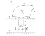
図1は、本発明の実施形態に係る無接点スイッチ100のブロック図である。無接点スイッチ100は、車載用のパワーウインドウスイッチとして用いられる。発光素子3は、赤色光または赤外線光を発生する。受光素子4は、発光素子3からの光を受光する。レンズ2は、発光素子3と受光素子4の間に設けられている。移動機構1には、ユーザが操作する操作子が含まれている。移動機構1は、操作子の操作に連動して、発光素子3の光軸に対して垂直な方向にレンズ2を移動させる。移動検出部5と水検出部6と信号出力部7は、例えばマイクロコンピュータ等から成る。移動検出部5は、受光素子4の受光量に基づいてレンズ2が移動した方向と量と速度を検出する。水検出部6は、受光素子4の受光量に基づいて水を検出する。信号出力部7は、移動検出部5と水検出部6の検出結果に応じた信号をパワーウインドウ用の制御装置に出力する。
FIG. 1 is a block diagram of a
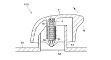
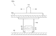
図2および図3は、無接点スイッチ100の構造図である。無接点スイッチ100のケース50の上部には、角筒51が設けられている。角筒51の平行な2側面には、図2に示すように軸52が設けられている。ノブ11の両平行な2側面には、穴12が設けられている。角筒51にノブ11を被せて、軸52を穴12に嵌め合わせることにより、ノブ11は角筒51に軸52を中心に回転可能に取り付けられる。ノブ11の内側には、レバー13がノブ11と一体で設けられている(詳細構造図示省略)。レバー13は、図2に示すように角筒51を貫通している。レバー13の先端には、凹部14が形成されている。凹部14は、スライダ15の上部に設けられた凸部16と係合されている。
2 and 3 are structural diagrams of the
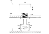
また、ノブ11の内側には、図3に示すように円筒17がノブ11と一体で設けられている。円筒17は、レバー13の側方にレバー13と平行に設けられている。円筒17は、角筒51に挿入されている。円筒17の内側には、プランジャ18とばね19が装着されている。角筒51の内側の円筒17の下方には、案内台53がケース50と一体で設けられている。レバー13は、案内台53の側方を通って、図2に示すようにケース50の内側に突出している。案内台53には、図3に示すようにV字形の窪み54が設けられている。プランジャ18は、ばね19によって窪み54に押し付けられている。窪み54の左右の傾斜面には、段差が設けられている。
Further, inside the
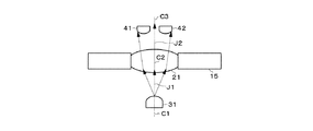
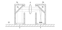
ケース50の内側には、図2に示すように基板60が設けられている。基板60には、マイクロコンピュータ等の電子部品と電気回路が実装されている。また、基板60の上面には、光パッケージ30が実装されている。光パッケージ30の本体は、図4に示すように凹型に形成されている。光パッケージ30の本体は、遮光性を有する合成樹脂から形成されている。光パッケージ30の本体の凹部の一方の側面には、1つのLED(Light Emitting Diode)31が設けられ、他方の側面には、2つのPD(Photodiode)41、42が設けられている。PD41、42は、左右方向へ並べられている。LED31は、図1の発光素子3の一例である。PD41、42は、図1の受光素子4の一例である。光パッケージ30の本体の底面からは、プレスフィット端子40が複数突出している。各プレスフィット端子40は、光パッケージ30に含まれる電気部品31、41、42等と基板60上の電気回路とを電気的に接続する。
Inside the
光パッケージ30の本体の凹部には、スライダ15が挿入されている。スライダ15は、遮光性を有する合成樹脂から形成されている。スライダ15には、レンズ21が埋め込まれている。レンズ21は、凸レンズから成り、図1のレンズ2の一例である。スライダ15とレンズ21の厚みは、LED31とPD41、42の間隔より小さくなっている。スライダ15は、図示しない壁に支持されて、厚み方向と上下方向へ移動できないようになっている。光パッケージ30の本体の下面からLED31、PD41、42、およびレンズ21の各中心までの高さは等しくなっている。LED31が発生した光は、レンズ21を透過して、PD41、42で受光される。
A
図2および図3に示す中立状態から、軸52を中心にノブ11を時計回りまたは反時計回りに回転操作することで、レバー13とプランジャ18が左右へ揺動し、スライダ15とレンズ21がLED31の光軸に対して垂直に左右へ平行移動する。この際、プランジャ18の揺動は、窪み54の左右の傾斜面によって案内される。また、プランジャ18が窪み54の傾斜面の段差を乗り越えることで、プランジャ18と案内台53の接触力が急激に変化して、節度感(クリック感)が発生する。そして、ノブ11の操作を解除すると、プランジャ18がばね19の弾性力によって、図3に示すように窪み54の底に押し付けられ、図2および図3に示すようにノブ11、レバー13、スライダ15、およびレンズ21が中立位置に戻って静止する。ノブ11やレンズ21等の移動体の理想的なF−S特性が得られるように、ノブ11、レバー13、スライダ15、および窪み54等は設計されている。ノブ11とレバー13は、操作子である。ノブ11、レバー13、スライダ15、角筒51、および軸52は、レンズ21を移動させる移動機構1(図1)である。円筒17、プランジャ18、ばね19、案内台53、および窪み54は、節度を発生させる節度機構である。
2 and 3, when the
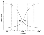
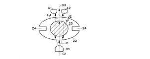
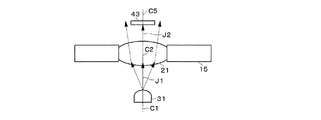
図5A〜図5Cは、LED31からの光のPD41、42での受光状態を示す図である。図6は、レンズ21の移動量に対するPD41、42の出力の変化状態を示す図である。図5A〜図5Cに示すようにPD41、42は、中間C3がLED31の中心C1とLED31のレンズ21入射前の光軸J1とに一致するように設けられている。図2等に示したようにノブ11、スライダ15、およびレンズ21等が中立位置にあるときは、図5Aに示すようにレンズ21の中心C2が、LED31の中心C1、LED31のレンズ21入射前の光軸J1、およびPD41、42の中間C3と一致する。このため、LED31のレンズ21出射後の光軸J2がレンズ21入射前の光軸J1およびPD41、42の中間C3と一致し、LED31からの光が、矢印で示すようにレンズ21を透過して、PD41、42に均等に受光される。そして、図6の真ん中に示すようにPD41、42から受光量に応じて出力される信号の電圧レベルを示す出力値が同等になる。つまり、PD41、42の受光量が同等になる。
5A to 5C are diagrams showing the light receiving states of the light from the
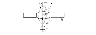
また、図2等でノブ11を反時計回りに回転操作して、スライド15とレンズ21を右へ移動させて行くと、図5Bに示すようにレンズ21の中心C2が、LED31の中心C1および光軸J1から右へずれて行く。このため、LED31のレンズ21出射後の光軸J2がレンズ21入射前の光軸J1とPD41、42の中間C3とに対して右へ傾いて行き、LED31からの光が、矢印で示すようにレンズ21を透過して、PD41よりPD42に多く受光される。そして、図6の右側に示すように、PD41の出力値が低下し、PD42の出力値が上昇し、PD41、42の出力値の差分が大きくなって行く。つまり、PD41の受光量が減少し、PD42の受光量が増加し、PD41、42の受光量の差分が大きくなって行く。
Further, when the
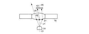
また、図2等でノブ11を時計回りに回転操作して、スライド15とレンズ21を左へ移動させて行くと、図5Cに示すようにレンズ21の中心C2が、LED31の中心C1および光軸J1から左へずれる。このため、LED31のレンズ21出射後の光軸J2がレンズ21入射前の光軸J1とPD41、42の中間C3とに対して左へ傾いて行き、LED31からの光が、矢印で示すようにレンズ21を透過して、PD42よりPD41に多く受光される。そして、図6の左側に示すように、PD42の出力値が低下し、PD41の出力値が上昇し、PD41、42の出力値の差分が大きくなって行く。つまり、PD42の受光量が減少し、PD41の受光量が増加し、PD41、42の受光量の差分が大きくなって行く。図6では、PD41、42の出力は中立位置に対して左右対称になっている。図1の移動検出部5には、図6に示すようなレンズ21の移動量に対するPD41、42の出力の変化を示す情報を予め記憶しておく。
Further, when the
図7は、PD41、42の出力値の差分を得る回路を示す図である。本回路は、光パッケージ30に設けられている。PD41、42の出力値は差動アンプに入力される。差動アンプは、所定の周期で、PD42からの入力値Vin2よりPD41からの入力値Vin1を減じた値と、抵抗値R3を抵抗値R1で除した値とを乗じて、PD41、42の出力値の差分Voutを算出し{Vout=(Vin2−Vin1)(R3/R1)}、移動検出部5へ出力する。抵抗値R3を抵抗値R1で除した値は、抵抗値R4を抵抗値R2で除した値と等しくなっている(R3/R1=R4/R2)。
FIG. 7 is a diagram illustrating a circuit that obtains a difference between output values of the PDs 41 and 42. This circuit is provided in the
移動検出部5は、所定の周期で、差動アンプからPD41、42の出力値の差分が入力されると、図6に示すようなレンズ21の移動量に対するPD41、42の出力の変化を示す情報を参照し、PD41、42の出力値の差分の極性(+または−)からレンズ21の移動方向(右または左)を検出し、PD41、42の出力値の差分の大きさからレンズ21の移動量を検出する。PD41、42の出力値の差分自体を、レンズ21の移動量とみなしてもよい。これ以外に、例えばPD41、42の出力値の大小関係と大きさとからレンズ21の移動方向と移動量とを検出してもよい。また、移動検出部5は、レンズ21の移動量を時間で微分して、レンズ21の移動速度を検出する。レンズ21の移動方向、移動量、および移動速度は、ノブ11の操作方向、操作量、および操作速度とみなせる。
When the difference between the output values of the PDs 41 and 42 is input from the differential amplifier at a predetermined period, the
図1の信号出力部7は、移動検出部5で検出したレンズ21の移動方向と移動量に応じて、ON若しくはOFFの信号または線形のアナログ信号等のスイッチ出力を発生させて、制御装置に出力する。例えばON/OFF信号を出力する場合は、図6に示すように、レンズ21の中立位置の右側に、マニュアルオープンオフ閾値MO−off、マニュアルオープンオン閾値MO−on、およびオートオープンオン閾値AO−onを設けて(0<MO−off<MO−on<AO−on)、移動検出部5または信号出力部7に予め記憶しておく。また、レンズ21の中立位置の左側に、マニュアルクローズオフ閾値MC−off、マニュアルクローズオン閾値MC−on、およびオートクローズオン閾値AC−onを設けて(0>MC−off>MC−on>AC−on)、移動検出部5または信号出力部7に予め記憶しておく。そして、レンズ21の左右への移動量が、マニュアルオープンオン閾値MO−on、オートオープンオン閾値AO−on、マニュアルクローズオン閾値MC−on、またはオートクローズオン閾値AC−onのいずれかを越えたときに、該閾値に対応するマニュアルオープンオン信号、オートオープンオン信号、マニュアルクローズオン信号、またはオートクローズオン信号を制御装置に出力する。また、マニュアルオープンオン信号またはマニュアルクローズオン信号を出力した後、レンズ21の左右への移動量がマニュアルオープンオフ閾値MO−offまたはマニュアルクローズオフ閾値MC−offを越えなくなったときに、該閾値に対応するマニュアルオープンオフ信号またはマニュアルクローズオフ信号を制御装置に出力する。
The
制御装置は、マニュアルオープン/クローズオン信号が入力されると、モータを駆動して、パワーウインドウを開閉し始め、マニュアルオープン/クローズオフ信号が入力されると、モータの駆動を停止して、パワーウインドウの開閉を停止する。また、制御装置は、オートオープン/クローズオン信号が入力されると、モータを駆動して、パワーウインドウを完全に開閉する。図6に示すようにマニュアルオープン/クローズオフ閾値MO/MC−offを、マニュアルオープン/クローズオン閾値MO/MC−onより中立位置側にある程度間隔をおいて設けているのは、ノブ11やレンズ21等のF―S特性に生じる履歴現象(ヒステリシス)に対処するためである。これにより、ノブ11に加わる荷重の微小変化で、レンズ21がマニュアルオープン/クローズオン閾値MO/MC−onの付近で微小移動しても、マニュアルオープン/クローズのオン信号とオフ信号が短時間に切り替わって繰り返し出力されるのを防止することができる。
When a manual open / close on signal is input, the controller starts driving the motor to open and close the power window. When a manual open / close off signal is input, the control device stops driving the motor and turns on the power. Stop opening and closing the window. Further, when the auto open / close on signal is input, the control device drives the motor to completely open and close the power window. As shown in FIG. 6, the manual open / close-off threshold value MO / MC-off is provided at some distance on the neutral position side from the manual open / close-on threshold value MO / MC-on. This is to cope with a hysteresis phenomenon (hysteresis) occurring in the FS characteristic such as 21. As a result, even if the
また、信号出力部7は、移動検出部5で検出したレンズの21の移動速度に応じた信号を発生させて、制御装置に出力する。制御装置は、レンズ21の移動速度に応じた信号が入力されると、例えば該信号に基づいてパワーウンインドウの開閉速度を変えるように制御する。
The
以上によると、LED31の特性のばらつきや環境変化や経時変化により、LED31の発光量が変動しても、これに伴うPD41、42の受光量の変動量は同等になり、PD41、42の受光量の差分は変動しない。このため、PD41、42の受光量や受光量の差分の変化から、移動体であるレンズ21の移動方向、移動量、および移動速度を正確に検出することができる。また、ノブ11等の操作方向、操作量、および操作速度も正確に検出することができる。つまり、LED31の特性のばらつきや環境変化や経時変化に対して、無接点スイッチ100を強健にすることが可能となる。
According to the above, even if the light emission amount of the
よって、検出したレンズ21の移動方向と移動量に応じて、ON/OFF信号または線形のアナログ信号等のスイッチ出力を確実に発生させて、制御装置に送ることが可能となる。特に、ON/OFF信号を出力する場合は、レンズ21の各方向の移動量の判断基準となる閾値を調整することで、ON/OFF信号の出力点をレンズ21の位置に応じて正確に設定することができる。また、上記閾値の数を増減することで、ON/OFF信号の出力点数を容易に増減することができる。つまり、ON/OFF信号の出力点を設定しまたは変更する際に、設計自由度が高く、部品の追加や変更の必要がなく、かかるコストを低く抑えることが可能となる。
Therefore, it is possible to reliably generate a switch output such as an ON / OFF signal or a linear analog signal according to the detected moving direction and moving amount of the
また、検出したレンズ21の移動速度に応じた信号を発生して制御装置に送ることができる。そしてこれにより、無接点スイッチ100で操作するパワーウインドウの開閉制御用のデータが増加するので、例えば制御装置でレンズ21の移動速度に基づいてパワーウインドウの開閉速度を変化させる等の制御を行うことが可能となる。
In addition, a signal corresponding to the detected moving speed of the
また、LED31からの光をPD41、42で常に受光すればよく、該光をノブ11の操作やレンズ21の位置に応じてPD41、42に対して透過したり遮断したりする必要がないので、各部品の製造と組み付けの精度をあまり厳しくしなくてもよくなり、無接点スイッチ100の製造を容易にすることができる。また、中立状態でレンズ21の中心をLED31の中心、光軸、およびPD41、42の中間に厳密に合わせなくても、例えば中立状態でのPD41、42の受光量(出力値)を初期値とすることで、または中立状態でのPD41、42の受光量(出力値)を均等になるようにオフセットすることで、レンズ21の移動方向、移動量、および移動速度を正確に検出することができる。
In addition, it is sufficient that the light from the
また、LED31からの光をレンズ21でPD41、42へ導くので、部品点数が少なく、無接点スイッチ100の製造を容易にすることができ、LED31とPD41、42の間隔を狭くして、無接点スイッチ100を小型化することができる。また、LED31、PD41、42、および差動アンプ等を含んだ回路を光パッケージ30に設けて基板60に実装しているので、構造が簡単で、LED31とPD41、42の位置合わせや、他の部品との組み付けや、ノイズと電磁波障害等の対策を容易に行うことが可能になる。
In addition, since the light from the
また、PD41、42の一方が故障した場合、該一方のPDの受光量が故障していない他方のPDの受光量に対して異常となり、両方の受光量の差分も異常となる。このため、レンズ21の位置にかかわりなく、一方のPDの受光量の異常または両方のPDの受光量の差分の異常により、一方のPDの故障を容易に検出することができる。
In addition, when one of the PDs 41 and 42 fails, the received light amount of the one PD becomes abnormal with respect to the received light amount of the other PD that has not failed, and the difference between both received light amounts also becomes abnormal. Therefore, regardless of the position of the
さらに、機械的接点が無いので、接点の接触不良といった不具合が生じず、寿命が長くなり、ノブ11等の移動機構、プランジャ18等の節度機構、およびレンズ21の動作が妨害されず、設計した理想的なレンズ21等のF−S特性を実現することができる。
Furthermore, since there is no mechanical contact, there is no problem such as contact failure, the life is extended, the movement mechanism such as the
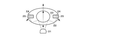
以上では、レンズ2として凸レンズ21を用いているが、これに代えて、図8Aおよび図8Bに示すような穴23と溝24が形成されたレンズ22を用いてもよい。レンズ22は、透明な楕円筒から成る。レンズ22は、凸レンズ21に代えて、スライダ15に埋め込まれる。レンズ22の穴23は、LED31の光軸J1に対して垂直に設けられている。レンズ22の溝24は、レンズ22のLED31とPD41、42に面しない外周部に穴23と平行に設けられている。レンズ22が中立位置にあるときは、レンズ22の中心C4がLED31の中心C1、光軸J1、J2、およびPD41、42の中間C3に一致する。レンズ22は、ノブ11の操作に連動して左右へ平行移動する。LED31からの光は、矢印で示すようにレンズ22、穴23、レンズ22の順に透過して、PD41、42で受光される。レンズ22の左右への平行移動に伴って、PD41、42の受光量が変化するため、該受光量の差分からレンズ22の移動方向、移動量、および移動速度が検出される。
In the above description, the
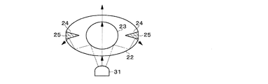
図8Aに示すように、穴23が空気で満たされているときは、レンズ22は凹レンズとして機能する。このため、LED31からの光は、矢印で示すように穴23とレンズ22の境界面で屈折して発散する。一方、水没等が原因で、図8Bに示すように、穴23に水Wが入って満たされたときは、レンズ22は凸レンズとして機能する。このため、LED31からの光は、矢印で示すようにレンズ22と水Wの境界面で屈折して収束する。よって、穴23に水Wが入っているときのPD41、42の受光量は、穴23に水Wが入っていないときのPD41、42の受光量に比べて多くなる。穴23に水Wが入っている場合と入っていない場合のPD41、42の出力値は、図2の水検出部6に予め記憶しておく。これにより、水検出部6は、穴23に水Wが入ってPD41、42の受光量が変化することに基づいて水Wを検出する。信号出力部7は、水検出部6で水Wを検出したことを示す信号を発生させて、制御装置に出力する。制御装置は、水Wの検出を示す信号が入力されると、水没等の水害が発生したと判断し、例えばモータを駆動して、パワーウンインドウを完全に開く。
As shown in FIG. 8A, when the
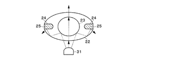
図9に示すようにレンズ22から溝24を省いた場合、LED31からの光の一部が、二点鎖線の矢印で示すようにレンズ22を透過して境界面で反射しながら穴23を回り込んで、PD41、42に入射してしまう。このため、PD41、42の受光量に基づいて穴23に水が入ったことを正確に検出できなくなるおそれがある。然るに、図8Aに示すようにレンズ22に溝24を設けると、LED31からの光の一部が、二点鎖線の矢印で示すようにレンズ22を透過して穴23を回り込んで行く途中で、レンズ22と溝24の境界面で反射して、PD41、42に入射しなくなる。このため、PD41、42の受光量に基づいて穴23に水が入ったことを正確に検出できるようになる。また、LED31からの光がレンズ22、穴23、レンズ22の順に透過して、PD41、42で受光されるのを、溝24により妨げることもない。
When the
また、図10に示すようにレンズ22の溝24に遮光体25を挿入することで、LED31からの光の一部が溝24を透過するのを遮光体25で阻止して、PD41、42に完全に入射しなくなる。レンズ22に設ける溝24と遮光体25の形状は、図8Aや図10に示すような四角形に限らず、例えば図11Aに示すような三角形、図11Bに示すような段差形、または図11Cに示すような長丸形等にしてもよい。つまり、溝24と遮光体25の形状は、遮光効果を発揮できるものであればよい。
Further, as shown in FIG. 10, by inserting a
上記によると、無接点スイッチ100が水没等の水害に遭っても、水Wがレンズ22の穴23に入ってPD41、42の受光量が変化することから水Wを検出することができる。そして、該検出結果を制御装置へ出力し、水害の発生を通知することが可能となる。また、LED31からの光の一部が穴23を回り込むようにレンズ22を透過してPD41、42に入射するのを、溝24や遮光体25で阻止することができ、PD41、42の受光量に基づいて穴23に水Wが入ったことを正確に検出することが可能となる。
According to the above, even if the
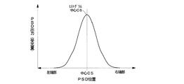
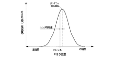
以上では、受光素子4としてPD41、42を用いているが、これに代えて、図12A〜図12Cに示すようなPSD(Position Sensitive Detector;位置検出素子)43を用いてもよい。図12A〜図12Cは、LED31からの光のPSD43での受光状態を示す図である。図13A〜図13Cは、PSD43の出力を左右方向の位置によりヒストグラム化した図である。図12A〜図12Cに示すようにPSD43は、中心C5がLED31の中心C1と一致するように、光パッケージ30に設けられている。レンズ21に代えて、図8A等に示したレンズ22を用いてもよい。
In the above, the
レンズ21等が中立位置にあるときは、図12Aに示すようにレンズ21の中心C2が、LED31の中心C1、PSD43の中心C5、およびLED31のレンズ21入射前後の光軸J1、J2と一致する。このため、LED31からの光が、矢印で示すようにレンズ21を透過して、PSD43に左右均等に受光され、図13Aに示すようにPSD43の出力のヒストグラムの中心C6がPSD43の中心C5と一致する。つまり、PSD43の受光位置の重心がPSD43の中心C5と一致する。
When the
また、ノブ11の回転操作により、スライド15とレンズ21を右へ移動させて行くと、図12Bに示すようにレンズ21の中心C2が、LED31の中心C1および光軸J1から右へずれて、LED31のレンズ21出射後の光軸J2がレンズ21入射前の光軸J1とPSD43の中心C5とに対して右へ傾いて行く。このため、LED31からの光が、矢印で示すようにレンズ21を透過して、PSD43に偏って受光され、図13Bに示すようにPSD43の出力のヒストグラムの中心C6がPSD43の中心C5から右へずれて行く。つまり、PSD43の受光位置の重心がPSD43の中心C5から右へずれて行く。
When the
また、ノブ11の回転操作により、スライド15とレンズ21を左へ移動させて行くと、図12Cに示すようにレンズ21の中心C2が、LED31の中心C1および光軸J1から左へずれて、LED31のレンズ21出射後の光軸J2がレンズ21入射前の光軸J1とPSD43の中心C5とに対して左へ傾いて行く。このため、LED31からの光が、矢印で示すようにレンズ21を透過して、PSD43に偏って受光され、図13Cに示すようにPSD43の出力のヒストグラムの中心C6がPSD43の中心C5から左へずれて行く。つまり、PSD43の受光位置の重心がPSD43の中心C5から左へずれて行く。
When the
PSD43の受光位置の重心C6とPSD43の中心C5とのずれ方向とずれ量は、レンズ21の移動方向と移動量に相当する。図1の移動検出部5は、所定の周期で、PSD43の受光位置に基づいてレンズ21の移動方向と移動量を検出する。また、移動検出部5は、レンズ21の移動量を時間で微分して、レンズ21の移動速度を検出する。図1の信号出力部7は、移動検出部5で検出したレンズ21の移動方向、移動量、および移動速度に応じた信号を発生させて、制御装置に出力する。
The shift direction and shift amount between the center of gravity C6 of the light receiving position of the
上記によると、LED31の特性のばらつきや経時変化により、LED31の発光量が変動しても、PSD43の受光位置は変動しないので、PSD43の受光位置の変化から、レンズ21の移動方向と移動量を正確に検出することができる。また、受光素子4として1つのPSD43を用いているので、部品点数がより少なくなり、無接点スイッチ100の製造を容易にすることができる。さらに、PD41、42を用いた場合と同様に、LED31の特性のばらつきや環境変化や経時変化に対して無接点スイッチ100を強健にしつつ、無接点スイッチ100を小型化することが可能となる。
According to the above, the light receiving position of the
以上では、本発明をノブ11等の操作子を揺動操作するタンブラスイッチに適用して、無接点スイッチ100としているが、これ以外に本発明を、例えば図14に示すようなスライドスイッチに適用して、無接点スイッチ100aとしてもよい。図14の無接点スイッチ100aでは、ノブ11aがケース50aに左右へ平行移動可能に取り付けられている。ノブ11aの下部には、プレート13aが一体で設けられている。プレート13aは、ケース50aの内部に突出していて、光パッケージ30の凹部に挿入されている。プレート13aには、レンズ21が光パッケージ30に設けられたLED31およびPD41、42と対向するように埋め込まれている。図14に示す中立状態からノブ11aを左右へ移動操作することで、プレート13aとレンズ21が左右へ平行移動して、LED31からの光のPD41、42での受光状態が変化し、PD41、42の受光量に基づいてレンズ21の移動方向、移動量、および移動速度が検出される。PD41、42に代えて、PSD43を用いてもよい。
In the above, the present invention is applied to the tumbler switch for swinging the operation element such as the
また、本発明を、例えば図15に示すようなプッシュスイッチに適用して、無接点スイッチ100bとしてもよい。図15の無接点スイッチ100bでは、ノブ11bがケース50bに下方へ押し込み可能に取り付けられている。ノブ11bの下部には、プレート13bが一体で設けられている。ケース50bの内部には、光パッケージ30bと基板60が設けられている。光パッケージ30bは、基板60に実装されている。光パッケージ30bの本体は、図4に示した光パッケージ30と同様に凹型に形成されている。光パッケージ30bの本体の凹部の一方の側面には、LED31が設けられ、他方の側面には、PD41、42が上下に並べて設けられている。プレート13bは、ケース50bの内部に突出していて、光パッケージ30bの凹部に挿入されている。プレート13bには、レンズ21がLED31およびPD41、42と対向するように埋め込まれている。図15に示す初期状態からノブ11bを下方へ押し込み操作することで、プレート13bとレンズ21が下方へ移動して、LED31からの光のPD41、42での受光状態が変化し、PD41、42の受光量に基づいてレンズ21の下方への移動量および移動速度が検出される。ノブ11bは、ばね19bの弾性力によって図15の初期位置へ戻される。PD41、42に代えて、PSD43を用いてもよい。
Further, the present invention may be applied to a push switch as shown in FIG. In the
以上では、LED3とPD41、42またはPSD43を光パッケージ30、30bに設けて、光パッケージ30、30bを基板60に実装しているが、これに代えて、例えば図16に示すようにLED等の発光素子3とPSD等の受光素子4を基板60に実装するようにしてもよい。また、受光素子4として、2つのPDを用いてもよい。発光素子3と受光素子4は、それぞれカバー9a、9bで覆われている。カバー9a、9bは所定の間隔をおいて基板60等に固定されている。カバー9a、9bの間には、レンズ2が図面に対して垂直に移動可能に設けられている。カバー9a、9bの対向する面の上部には、レンズ2と対向するように開口が設けられている。カバー9a、9bの内側の上部には、ミラー8a、8bが設けられている。発光素子3からの光は、ミラー8aで反射して、レンズ2を透過し、ミラー8bで反射して、受光素子4で受光される。受光素子4の受光位置または受光量の変化に基づいて、レンズ2の移動方向、移動量、および移動速度が検出される。
In the above, the
以上では、移動検出部5がPD41、42の受光量またはPSD43の受光位置に基づいてレンズ21、22の移動方向、移動量、および移動速度を全て検出しているが、これに限らず、該レンズ21、22の移動方向、移動量、および移動速度のうち少なくとも1つを検出するようにしてもよい。
In the above, the
以上では、本発明をパワーウインドウスイッチに適用した例を挙げたが、本発明はこれに限らず、操作対象に何らかの動作を行わせるために操作するスイッチ全般に適用することが可能である。 In the above, an example in which the present invention is applied to a power window switch has been described. However, the present invention is not limited to this, and can be applied to all switches that are operated to cause an operation target to perform some operation.
1 移動機構
2 レンズ
3 発光素子
4 受光素子
5 移動検出部
6 水検出部
7 信号出力部
11、11a、11b ノブ
13 レバー
13a、13b プレート
15 スライダ
21 レンズ
22 レンズ
23 穴
24 溝
31 LED
41、42 PD
43 PSD
51 角筒
52 軸
J1 LEDの光軸
100、100a、100b 無接点スイッチ
DESCRIPTION OF SYMBOLS 1
41, 42 PD
43 PSD
51
Claims (7)
前記発光素子からの光を受光する第1の受光素子および第2の受光素子と、
前記発光素子と前記第1および前記第2の受光素子との間に設けられたレンズと、
前記発光素子の光軸に対して垂直な方向に前記レンズを移動させる移動機構と、
前記第1および前記第2の受光素子の受光量に基づいて前記レンズが移動した量を検出する移動検出手段と、を備えたことを特徴とする無接点スイッチ。 A light emitting element for generating light;
A first light receiving element and a second light receiving element for receiving light from the light emitting element;
A lens provided between the light emitting element and the first and second light receiving elements;
A moving mechanism for moving the lens in a direction perpendicular to the optical axis of the light emitting element;
A contactless switch, comprising: a movement detecting unit that detects an amount of movement of the lens based on the amount of light received by the first and second light receiving elements.
前記発光素子からの光を受光する第1の受光素子および第2の受光素子と、
前記発光素子と前記第1および前記第2の受光素子との間に設けられたレンズと、
前記発光素子の光軸に対して垂直な方向に前記レンズを移動させる移動機構と、
前記第1および前記第2の受光素子の受光量に基づいて前記レンズが移動した方向と量を検出する移動検出手段と、を備えたことを特徴とする無接点スイッチ。 A light emitting element for generating light;
A first light receiving element and a second light receiving element for receiving light from the light emitting element;
A lens provided between the light emitting element and the first and second light receiving elements;
A moving mechanism for moving the lens in a direction perpendicular to the optical axis of the light emitting element;
A contactless switch, comprising: a movement detecting means for detecting a direction and an amount of movement of the lens based on the amount of light received by the first and second light receiving elements.
前記第1および前記第2の受光素子は、前記レンズの移動方向へ並べて設けられ、
前記移動検出手段は、前記第1および前記第2の受光素子の受光量の差分に基づいて前記レンズが移動した方向と量を検出することを特徴とする無接点スイッチ。 The contactless switch according to claim 2,
The first and second light receiving elements are arranged in the moving direction of the lens,
The contactless switch, wherein the movement detecting means detects a direction and an amount of movement of the lens based on a difference in received light amount of the first and second light receiving elements.
前記第1および前記第2の受光素子に代えて、前記発光素子からの光を受光する位置検出素子を備え、
前記移動検出手段は、前記位置検出素子の受光位置に基づいて前記レンズが移動した方向と量を検出することを特徴とする無接点スイッチ。 The contactless switch according to claim 2,
In place of the first and second light receiving elements, a position detection element that receives light from the light emitting element is provided,
The contactless switch, wherein the movement detecting means detects the direction and amount of movement of the lens based on the light receiving position of the position detecting element.
前記移動検出手段は、前記レンズの移動量に基づいて移動速度を検出することを特徴とする無接点スイッチ。 The contactless switch according to claim 2,
The contactless switch, wherein the movement detecting means detects a moving speed based on a moving amount of the lens.
前記レンズに前記発光素子の光軸に対して垂直に穴を設け、
前記穴に水が入って前記受光素子の受光量が変化することに基づいて水を検出する水検出手段を備えたことを特徴とする無接点スイッチ。 The contactless switch according to claim 2,
Providing a hole perpendicular to the optical axis of the light emitting element in the lens;
A contactless switch comprising water detection means for detecting water based on a change in the amount of light received by the light receiving element due to water entering the hole.
前記レンズの前記発光素子と前記受光素子に面しない外周部に前記穴と平行に溝を設けたことを特徴とする無接点スイッチ。 The contactless switch according to claim 6,
A contactless switch, wherein a groove is provided in an outer peripheral portion of the lens that does not face the light emitting element and the light receiving element in parallel with the hole.
Priority Applications (1)
| Application Number | Priority Date | Filing Date | Title |
|---|---|---|---|
| JP2006305411A JP2008123797A (en) | 2006-11-10 | 2006-11-10 | Contactless switch |
Applications Claiming Priority (1)
| Application Number | Priority Date | Filing Date | Title |
|---|---|---|---|
| JP2006305411A JP2008123797A (en) | 2006-11-10 | 2006-11-10 | Contactless switch |
Publications (1)
| Publication Number | Publication Date |
|---|---|
| JP2008123797A true JP2008123797A (en) | 2008-05-29 |
Family
ID=39508339
Family Applications (1)
| Application Number | Title | Priority Date | Filing Date |
|---|---|---|---|
| JP2006305411A Pending JP2008123797A (en) | 2006-11-10 | 2006-11-10 | Contactless switch |
Country Status (1)
| Country | Link |
|---|---|
| JP (1) | JP2008123797A (en) |
Cited By (2)
| Publication number | Priority date | Publication date | Assignee | Title |
|---|---|---|---|---|
| JP2014093396A (en) * | 2012-11-02 | 2014-05-19 | Miyachi Technos Corp | Laser power supply device |
| JP2018136587A (en) * | 2017-02-20 | 2018-08-30 | 金陵電機株式会社 | Attitude detection mechanism, control method using the same, and lever device |
Citations (6)
| Publication number | Priority date | Publication date | Assignee | Title |
|---|---|---|---|---|
| JPS62249322A (en) * | 1986-04-23 | 1987-10-30 | 松下電器産業株式会社 | Switching device |
| JPH06249969A (en) * | 1993-02-26 | 1994-09-09 | Omron Corp | Photoelectric switch and detecting method |
| JPH10185557A (en) * | 1996-12-26 | 1998-07-14 | Yazaki Corp | Inclination sensor |
| JPH10214546A (en) * | 1996-11-29 | 1998-08-11 | Omron Corp | Optical sensor, limited region type optical sensor, optical disk discriminating sensor, optical disk tilt detecting sensor, copying device, and moving body detecting device |
| JP2002181624A (en) * | 2000-12-18 | 2002-06-26 | Sunx Ltd | Multi-optical-axis photoelectric sensor |
| JP2002352655A (en) * | 2001-05-25 | 2002-12-06 | Toshiba Eng Co Ltd | Non-contact switch |
-
2006
- 2006-11-10 JP JP2006305411A patent/JP2008123797A/en active Pending
Patent Citations (6)
| Publication number | Priority date | Publication date | Assignee | Title |
|---|---|---|---|---|
| JPS62249322A (en) * | 1986-04-23 | 1987-10-30 | 松下電器産業株式会社 | Switching device |
| JPH06249969A (en) * | 1993-02-26 | 1994-09-09 | Omron Corp | Photoelectric switch and detecting method |
| JPH10214546A (en) * | 1996-11-29 | 1998-08-11 | Omron Corp | Optical sensor, limited region type optical sensor, optical disk discriminating sensor, optical disk tilt detecting sensor, copying device, and moving body detecting device |
| JPH10185557A (en) * | 1996-12-26 | 1998-07-14 | Yazaki Corp | Inclination sensor |
| JP2002181624A (en) * | 2000-12-18 | 2002-06-26 | Sunx Ltd | Multi-optical-axis photoelectric sensor |
| JP2002352655A (en) * | 2001-05-25 | 2002-12-06 | Toshiba Eng Co Ltd | Non-contact switch |
Cited By (2)
| Publication number | Priority date | Publication date | Assignee | Title |
|---|---|---|---|---|
| JP2014093396A (en) * | 2012-11-02 | 2014-05-19 | Miyachi Technos Corp | Laser power supply device |
| JP2018136587A (en) * | 2017-02-20 | 2018-08-30 | 金陵電機株式会社 | Attitude detection mechanism, control method using the same, and lever device |
Similar Documents
| Publication | Publication Date | Title |
|---|---|---|
| DK2854296T3 (en) | CONTACT LESS BUTTON | |
| US9838006B2 (en) | Switch module of photoelectric integrated mechanical shaft keyboard | |
| JP2004138235A (en) | Shift lever device | |
| KR102071397B1 (en) | Shift lever device for actuating a vehicle gearbox | |
| CN108124459B (en) | Device for detecting position of driving gear selection lever and motor vehicle | |
| TWI618105B (en) | Photoelectric integrated mechanical axis keyboard switch module | |
| JP2008123797A (en) | Contactless switch | |
| TWI441218B (en) | Switch | |
| TWI717899B (en) | Key structure and keyboard | |
| TWI430307B (en) | Switch | |
| JP4909103B2 (en) | Operating device and electronic device | |
| WO2004095487A1 (en) | 3-position enable device | |
| WO2016035331A1 (en) | Multidirectional input device | |
| KR101417468B1 (en) | Gear position switch | |
| JP4860197B2 (en) | Distance setting type photoelectric sensor | |
| JP2008137441A (en) | Shift lever device | |
| US20240019888A1 (en) | Push-type input device and push-type shifter device | |
| CN111220066B (en) | Braking depth detection device with brake switch and vehicle | |
| JP4938258B2 (en) | Distance setting type photoelectric sensor | |
| JPH08241658A (en) | Photo-sensing type switch | |
| JP2023016235A (en) | Blade driving device | |
| JP2010272298A (en) | Multidirectional input device | |
| CN111768995A (en) | Key mechanism | |
| JPH1090007A (en) | Position-detecting sensor | |
| JPWO2018225399A1 (en) | Push type shift device |
Legal Events
| Date | Code | Title | Description |
|---|---|---|---|
| A621 | Written request for application examination |
Effective date: 20090220 Free format text: JAPANESE INTERMEDIATE CODE: A621 |
|
| A711 | Notification of change in applicant |
Effective date: 20100726 Free format text: JAPANESE INTERMEDIATE CODE: A712 |
|
| A977 | Report on retrieval |
Free format text: JAPANESE INTERMEDIATE CODE: A971007 Effective date: 20110301 |
|
| A02 | Decision of refusal |
Free format text: JAPANESE INTERMEDIATE CODE: A02 Effective date: 20111004 |