JP2008089590A - System for clearance measurement, and operation method of system - Google Patents
System for clearance measurement, and operation method of system Download PDFInfo
- Publication number
- JP2008089590A JP2008089590A JP2007245124A JP2007245124A JP2008089590A JP 2008089590 A JP2008089590 A JP 2008089590A JP 2007245124 A JP2007245124 A JP 2007245124A JP 2007245124 A JP2007245124 A JP 2007245124A JP 2008089590 A JP2008089590 A JP 2008089590A
- Authority
- JP
- Japan
- Prior art keywords
- probe
- plasma
- current
- detection system
- impedance
- Prior art date
- Legal status (The legal status is an assumption and is not a legal conclusion. Google has not performed a legal analysis and makes no representation as to the accuracy of the status listed.)
- Pending
Links
Images


Classifications
-
- G—PHYSICS
- G01—MEASURING; TESTING
- G01B—MEASURING LENGTH, THICKNESS OR SIMILAR LINEAR DIMENSIONS; MEASURING ANGLES; MEASURING AREAS; MEASURING IRREGULARITIES OF SURFACES OR CONTOURS
- G01B7/00—Measuring arrangements characterised by the use of electric or magnetic techniques
- G01B7/14—Measuring arrangements characterised by the use of electric or magnetic techniques for measuring distance or clearance between spaced objects or spaced apertures
-
- F—MECHANICAL ENGINEERING; LIGHTING; HEATING; WEAPONS; BLASTING
- F05—INDEXING SCHEMES RELATING TO ENGINES OR PUMPS IN VARIOUS SUBCLASSES OF CLASSES F01-F04
- F05D—INDEXING SCHEME FOR ASPECTS RELATING TO NON-POSITIVE-DISPLACEMENT MACHINES OR ENGINES, GAS-TURBINES OR JET-PROPULSION PLANTS
- F05D2270/00—Control
- F05D2270/01—Purpose of the control system
- F05D2270/17—Purpose of the control system to control boundary layer
- F05D2270/172—Purpose of the control system to control boundary layer by a plasma generator, e.g. control of ignition
Abstract
Description
本発明は、概ねプローブおよびセンサシステムに関し、より具体的には2つの物体の間の間隔を測定するためのプローブに関する。 The present invention relates generally to probe and sensor systems, and more specifically to a probe for measuring the spacing between two objects.
様々な種類のプローブおよびセンサシステムが2つの物体の間の距離を測定するために使用されてきている。加えて、プローブ装置は様々な用途に使用されてきている。例えば、タービンは、シュラウドに近接して配置されたいくつかのタービン翼を有する。タービン翼とシュラウドの間の間隔は、タービン翼の温度に応じて変動する。例えば、シュラウドとタービン翼の間の間隔は、タービンが冷たいときに最大であり、タービンが温まると次第に減少する。 タービン翼とシュラウドの間の間隙または間隔は、タービンの安全および効果的な動作のために維持されることが望ましい。センサはタービン内に配置されて、タービン翼とシュラウドの間の距離を測定することができる。この距離を使用して、シュラウドの移動を統制し、シュラウドとタービン翼の間の所望の変位を維持することができる。 Various types of probe and sensor systems have been used to measure the distance between two objects. In addition, probe devices have been used in a variety of applications. For example, the turbine has a number of turbine blades positioned proximate to the shroud. The spacing between the turbine blade and the shroud varies depending on the temperature of the turbine blade. For example, the spacing between the shroud and the turbine blades is greatest when the turbine is cold and gradually decreases as the turbine warms up. The gap or spacing between the turbine blade and the shroud is desirably maintained for safe and effective operation of the turbine. A sensor can be placed in the turbine to measure the distance between the turbine blade and the shroud. This distance can be used to control shroud movement and maintain the desired displacement between the shroud and the turbine blade.
タービンおよび圧縮機などの回転する構成部品の効率も回転翼と構成部品のケーシングとの間の間隙または間隔によって強く影響される。概して、間隙が最小になると構成部品の効率は最大になる。しかし、少量の間隔は、回転翼が構成部品のケーシングに当たるのを防ぐために望ましい。ある種の用途では、キャパシタンスプローブが2つの物体の間の距離を測定するために使用される。プローブは一方の物体の上に位置し、2つの物体の間の間隔を見積もるために他方の物体に対するキャパシタンスを測定する。しかし、ガスタービンなどの高温での用途については、既存の装置は、これを過酸な動作環境で動作させるために必要な要件が厳しいため、高価であり製造が難しい。
したがって、上記の問題点に対処するように改善されたセンサシステムの必要性がある。 Accordingly, there is a need for an improved sensor system that addresses the above problems.
本発明の実施形態により、間隔検出システムが提供される。このシステムは、可変距離dによって検査対象から離間されたプローブを含む。このシステムはまた、プローブを介して電流を供給するための交流(AC)電源も含み、AC電源およびプローブは、プローブの先端と検査対象の間に制御されたプラズマチャネルを生成するように構成される。システムはさらに、プローブの先端と検査対象の間の電圧差に基づいて可変距離dを決定するように構成された処理ユニットを含む。 According to an embodiment of the present invention, an interval detection system is provided. The system includes a probe that is spaced from the test object by a variable distance d. The system also includes an alternating current (AC) power source for supplying current through the probe, where the AC power source and the probe are configured to generate a controlled plasma channel between the probe tip and the test object. The The system further includes a processing unit configured to determine the variable distance d based on the voltage difference between the probe tip and the test object.
本発明の別の実施形態によると、導電性回転体への距離を測定する方法が開示される。この方法は、導電性回転体から可変距離dにプローブを配置する段階を含む。この方法はさらにプローブの先端と導電性回転体の間でプラズマ放電を開始し、安定させる段階を含む。方法はさらに、プローブの先端と導電性回転体の間に形成されたプラズマを介する電圧降下、電流、およびプローブのインピーダンスの少なくとも1つを測定する段階を含む。加えてこの方法は、電圧降下、電流、およびインピーダンスの少なくとも1つに基づいて、導電性回転体への距離を決定する段階を含む。 According to another embodiment of the present invention, a method for measuring a distance to a conductive rotor is disclosed. The method includes placing a probe at a variable distance d from the conductive rotator. The method further includes initiating and stabilizing a plasma discharge between the probe tip and the conductive rotor. The method further includes measuring at least one of a voltage drop, current, and probe impedance through a plasma formed between the probe tip and the conductive rotor. In addition, the method includes determining a distance to the conductive rotor based on at least one of voltage drop, current, and impedance.
本発明のこれらおよび他の特徴、態様、および利点は、図面にわたって同様の符号が同様の部品を表す添付の図面を参照して以下の詳細な記述が読まれるとき、よりよく理解されることになるだろう。 These and other features, aspects and advantages of the present invention will be better understood when the following detailed description is read with reference to the accompanying drawings in which like numerals represent like parts throughout the drawings, and wherein: It will be.
以下に詳細に述べるように、本発明の実施形態は間隔検出システムおよびそのシステムを操作する方法を含む。本明細書で使用されるように、「プラズマ放電」は大気圧下で約1MHzより大きい周波数を有する高周波で発生したプラズマを表す。 As described in detail below, embodiments of the present invention include an interval detection system and a method of operating the system. As used herein, “plasma discharge” refers to a plasma generated at a high frequency having a frequency greater than about 1 MHz at atmospheric pressure.
ここで図を参照すると、図1はプラズマを開始および安定させるためのシステム10の概略図である。システム10はまたプラズマプローブ10と称されることもできる。プラズマプローブ10は交流(AC)電圧源14に結合された内部導体12を含む。例示された実施形態では、複数の巻線18を含む外部導体16が内部導体12の周りに配置される。外部導体16は、一方の端部でAC電圧源14に結合され、反対側の端部で第1の電極20を形成する。第2の電極22は、プラズマ放電26を開始するための間隙24によって第1の電極20から離間される。特定の一実施形態では、内部導体12は円筒の形状の導体を含む。別の実施形態では、内部導体12はワイヤを含む。一例では、外部導体16はソレノイドである。一つの例示的な実施形態では、内部導体12は接地されている。別の実施形態では、外部導体16はAC電圧源14を介して接地される。一例では、プラズマ放電26は、約6MHzと約7.5MHzの間の範囲内の周波数を有する大気圧高周波プラズマを開始する。特定の一実施形態では、内部導体12および外部導体16は、プラズマ放電26を開始するためにAC電圧源14によって供給される電圧を少なくとも約20dB上げるように構成される。
Referring now to the drawings, FIG. 1 is a schematic diagram of a
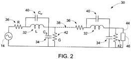
図2は、図1のプラズマプローブ10の等価回路30である。例示された実施形態では、図1で示される内部導体12および図1で示される外部導体16は一連のLC回路として構成され、Lはインダクタ32によって表される外部導体16のインダクタンスであり、CSはキャパシタ34によって表される、内部導体12と外部導体16の間のキャパシタンスである。インダクタ32は、抵抗36によって表される小さい実数の抵抗を有してよい。特定の一実施形態では、抵抗36は約10オームと約100オームの間で変化してよい。図1で示されるプラズマプローブ10は、内部導体12および外部導体16を介して分布した伝送線路38を有する4分の1波長変圧器として作用する。外部導体16は、単位長さ当たりのインダクタンスを増加させるために図1で示される多数の巻線18を含んでよい。巻線18は、巻線18のそれぞれの間に寄生キャパシタンス40を含んでよく、この寄生キャパシタンスはCSによって示されるキャパシタンス34よりもずっと小さい。したがって、寄生キャパシタンス40は無視してよい。等価回路30はまたキャパシタンス34の漏れ抵抗42も含んでよく、この漏れ抵抗はGによって示される。漏れ抵抗42は非常に小さく、したがって無視してよい。
FIG. 2 is an
プラズマが開始されるより前に、負荷がないとき、AC電圧源14は開放状態の回路の伝送線路に遭遇する。等価回路30は4分の1波長で共振する。伝送線路38の物理長が、定在波の波長の4分の1になるように電圧源の周波数が伝送線路38で定在波を生成するときに、4分の1波長共振が発生する。したがって電圧源14は、負荷46を生じる、伝送線路38の端部44における短絡に遭遇する。これによって、伝送線路38へ大量の電流が導かれることになる。生成された大電流はインダクタ32およびキャパシタ34を通って進む。さらに、2pfL(fは電圧源14の周波数である)によって与えられるインダクタ32のインピーダンスは、Lおよびfの両方が大きいとき大きい。したがって、インダクタ32にかかる電圧降下は大きくなり、伝送線路38の端部44で高電圧を生じる。この高電圧によって負荷46でのプラズマの生成が開始される。
Before the plasma is started, when there is no load, the
プラズマの生成は負荷46で伝送線路38を短絡させることになる。このような状況では、伝送線路38に導かれる電流は、2つの経路を有することができる。この経路の一方は、上述したようにインダクタ32を介しており、他方はインダクタ32をバイパスして負荷46を介している。したがって、電流は2つの経路に分別され、より少量の電流がインダクタ32を流れる。これによりインダクタ32にかかる電圧降下はより低くなり、この電圧降下は負荷46で発生したプラズマを介する電圧でもある。したがって、プラズマに流入する電流は減少し、その結果としてプラズマ抵抗が増加する。非常に速い負のフィードバックループが生成され、これにより負荷46で生成されたプラズマを安定させる。したがって、プラズマプローブ10は、プラズマを開始させ、次いでプラズマを消失させないように所望の値に電圧を安定させ、同時に発生する恐れのある任意の燃焼を防ぐことにおいて重要な役割を果たす。
The generation of plasma causes the
本発明の別の例示の実施形態では、図3が、プラズマ生成を開始させ安定させるための遮蔽されたプローブシステム60を示す。システム60は、一方の端部がAC電圧源64に結合され、反対側の端部で第1の電極66を形成する中央導体62を含む。システム60はまた、中央導体62の周りに配置される複数の巻線70を含む外部導体68も含む。例示の実施形態について、外部導体68は一方の端部でAC電圧源64に結合され、反対側の端部で第2の電極72を形成する。第1の電極66および第2の電極72は、間隙74によって分離されてプラズマ放電76を開始する。遮蔽されたプローブシステム60は、遮蔽されていないプローブよりもより高温のプラズマ放電、すなわち温プラズマ放電を開始することができる。システム60はさらに電磁干渉遮蔽のために中央導体62と同心に配置される遮蔽体78を含む。外部導体68によって生成される磁気領域は圧縮され、中央導体62と遮蔽体78の間の空間に存在する。中央導体62および外部導体68は、約30dBほどAC電圧源64の電圧を上げるように構成されてよい。絶縁体80は中央導体62と遮蔽体78の間に配置されてよい。特定の一実施形態では、絶縁体80はセラミック絶縁体を含んでよい。例では、遮蔽体78は内部伝導性シリンダおよび外部伝導性シリンダを含んでよく、これらのシリンダは同心でお互いに接続され、外部導体68は内部伝導性シリンダと外部伝導性シリンダの間に配置されてよい。
In another exemplary embodiment of the present invention, FIG. 3 shows a shielded
図4は、図3の遮蔽されたプローブシステム60の等価回路90である。例示された実施形態について、図3の中央導体62および図3の外部導体68は一連のLC回路として構成される。図3で示される遮蔽体78があることにより、回路90の実効インダクタンスが減少し、実効キャパシタンスが増加する。実効インダクタンスは、インダクタ92によって示される(L−M)に相当し、Lは中央導体のインダクタンスであり、Mは渦電流損による中央導体62と遮蔽体78の間の相互インダクタンスである。実効キャパシタンスは、キャパシタ94によって示される(CS1+CS2)に相当し、CS1は中央導体62と外部導体68の間のキャパシタンスであり、CS2は遮蔽体78と外部導体68の間のキャパシタンスである。インダクタ92は、渦電流損による抵抗を含む、抵抗96によって示される小さい実数の抵抗を有してよい。キャパシタ94は漏れ抵抗98によって示される無視できる漏れ抵抗を含んでよい。回路90は、図3に示される巻線70のそれぞれの間のキャパシタ100によって示される無視できる寄生キャパシタンスを含んでもよい。実効インダクタンスがより小さく、渦電流の形態での損失がより多いので、プラズマ放電を開始するために必要な電圧が増加する。プラズマ放電の開始は、負荷104を有する端部102での短絡を引き起こす。したがって、これにより図1に示すプラズマプローブに比べてより効率が低いプラズマプローブをもたらす可能性がある。
FIG. 4 is an
図5は、間隔検出システム110の構成図を示す。システム110は、「d」によって示される可変距離116によって検査対象114から離間されたプローブ112を含む。特定の実施形態では、検査対象114は導電性回転検査対象114である。特定の一実施形態では、プローブ112はタングステン、鉄、ニッケル、およびアルミニウムからなる群から選択される材料から作製されるワイヤを含んでよい。別の実施形態では、プローブ112は高周波(RF)プラズマプローブであってよい。例えば、RFプラズマプローブは約6MHzと約7.5MHzの間の範囲の動作周波数を有してよい。特定の一実施形態では、RFプラズマプローブは図1に示すように遮蔽されていないプラズマプローブである。別の実施形態では、RFプラズマプローブは、例えば図3に示すような遮蔽されたプラズマプローブである。交流(AC)電源118はプローブ112に電流を供給するために設けられる。特定の実施形態については、AC電源 118はプローブ112に一定の電流量を供給する。制御されるプラズマチャネル120はプローブ112の先端と検査対象114の間で生成されることができる。プラズマチャネルのインピーダンスは主として抵抗であり、プラズマチャネルを通って流れる電流、チャネルの長さ、およびチャネル内の気体の性質(例えば気体の成分、圧力、および温度)に応じて約1キロオームと500キロオームの範囲で変化することができる。特定の実施形態では、プラズマは一定の電流、高周波数(少なくとも約20kHz)の電源118を使用して安定する。電圧および電流プローブ122を使用して、プローブ112の先端と回転検査対象114の間の電圧差を測定することができる。システム110はまた、プローブ112の先端と回転検査対象114の間で測定した電圧差に基づいて可変距離「d」116を決定するように構成された処理ユニット124を含む。電圧差はプローブ112のインピーダンスの変化に対応する。プローブ112のインピーダンスの変化は、距離「d」116に比例する。特定の一実施形態では、処理ユニット124は測定したインピーダンスの変化と較正データを比較して「d」116を決定するように構成される。例では、回転検査対象114はタービンまたは圧縮機の部分、例えばタービン翼であってよい。別の実施形態では、可変距離「d」116は約1μmから約20mmの間の範囲であってよい。
FIG. 5 shows a configuration diagram of the
本発明は、本発明の処理タスクを実行するための任意の特定の処理ユニットに限定されるものではないことに留意されたい。「処理ユニット」という用語は、この用語が本明細書で使用されると、本発明のタスクを実行するために必要な計算または演算を実行することが可能な任意の機械を示すように意図されている。「処理ユニット」という用語は、体系的な入力を受け入れること、および規定の規則に従ってその入力を処理して出力を生成することが可能である任意の機械を示すように意図されている。本明細書で使用されるような「構成される」という表現は、当業者によって理解されるように、処理ユニットが本発明のタスクを実行するためのハードウェアおよびソフトウェアの組合せを装備していることを意味するということもやはり留意されたい。 It should be noted that the present invention is not limited to any particular processing unit for performing the processing tasks of the present invention. The term “processing unit”, as the term is used herein, is intended to indicate any machine capable of performing the calculations or operations necessary to perform the tasks of the present invention. ing. The term “processing unit” is intended to indicate any machine that is capable of accepting systematic input and processing that input according to defined rules to produce an output. The expression “configured” as used herein is equipped with a combination of hardware and software for a processing unit to perform the tasks of the present invention, as will be appreciated by those skilled in the art. It should also be noted that this means.
図6は間隔検出システム110の特定の例を示す構成図である。例示の実施形態では、AC電流源はRF搬送波源134を備える。RF搬送波源134からのRF信号132は、RF信号132を増幅するRF増幅器136に送り込まれる。示された例ではRF増幅器136はRF信号を50dB増幅する。増幅されたRF搬送波信号138は図5で示されるRFプラズマプローブ112に入力されて、図5で示されるように、RFプラズマプローブ112と回転検査対象114の間の間隙116でプラズマを生成し、維持する。上述したように、プラズマチャネルのインピーダンスは主として抵抗であり、プラズマチャネルを通って流れる電流、チャネルの長さ、およびチャネル中の気体の性質に応じて約1キロオームと500キロオームの範囲で変わることができる。プラズマが開始されると、負荷のインピーダンスが増加する。例では、インピーダンスは約50オームから約3キロオームへ増加することができる。RF増幅器136からの増幅された搬送波信号138は減衰器140に送り込まれて、増幅されたRF搬送波信号138の電圧を減衰された信号レベル142まで減少させ、また生成されたプラズマのインピーダンスを変化させることなく電圧を測定するようにする。例示の実施形態では、減衰器140は、例えば約10キロオームから約100キロオームのインピーダンスを有する高インピーダンス減衰器である。減衰された信号142は次いで、減衰された信号142から包絡線信号146を分割する復調器144へ入力される。約7MHzなどの 搬送波周波数で様々な源からの複数の電磁干渉信号がある。干渉信号を避けるために、包絡線信号146は分離される。包絡線信号146はさらに、包絡線信号146の電圧の変化を測定するために図5に示される処理ユニット124に送り込まれる。
FIG. 6 is a configuration diagram illustrating a specific example of the
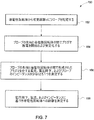
図7は、導電性回転体までの距離を測定する方法150についての例示的な段階を示す流れ図である。方法150は、段階152で導電性回転体から可変距離dにプローブを配置することを含む。段階154で、プローブの先端と導電性回転体の間のプラズマ放電が開始され安定する。特定の一実施形態では、プラズマ放電は、プラズマを介する電流を減少させるためにプローブにフィードバックを与えることにより安定する。段階156で、電圧降下がプローブの先端と回転体の間のプラズマを介して測定される。別の実施形態では、段階156で電流がプラズマを介して測定される。さらに別の実施形態では段階156でさらに、測定された電圧降下および電流からインピーダンスが決定される。概して、複素インピーダンスは測定された電圧降下と一定の電流量の比に等しい。さらに別の実施形態では、プラズマプローブのインピーダンスが測定される。段階158で、回転体についての間隔が、測定された電圧、電流、および複素インピーダンスの大きさの少なくとも1つから決定される。間隔の決定には、複素インピーダンスと較正データを比較することを含む。
実施例
以下の実施例は単なる例示であり、請求の範囲に記載されている発明の範囲を限定すると解釈されるべきではない。
FIG. 7 is a flow diagram illustrating exemplary steps for a
EXAMPLES The following examples are illustrative only and should not be construed as limiting the scope of the invention as recited in the claims.
図8はテスト用具160の一部分の概略図である。テスト用具160は、例えばタービン翼を示すことができる突出部162および中央部分164を含む。突出部162とケーシングまたはシュラウド(図示せず)の間の間隔の最適な距離が決定されることになる。さらに突出部162のそれぞれは縁部166および中央平坦部168を含む。底平坦部170は中央部分164の縁部を示す。
FIG. 8 is a schematic view of a portion of the
図9は、図5で示されるRFプラズマプローブ112の先端と図8の回転テスト用具160の様々な部分の間で測定された電圧差を時間の関数として示したグラフ180である。テスト用具160の先端の回転速度は約0.4m/secに設定された。X軸182は秒単位での経過時間を表し、Y軸184は回転テスト用具の様々な部分がプラズマ放電を通るときの図6で示される包絡線信号146の電圧を表す。頂点186は、タービン翼162の図8に示される縁部166で測定された電圧を示す。同様に点188は突出部162の図8に示される中央平坦部168で測定された電圧を示し、点190は突出部162の間の図8に示される底平坦部170で測定された電圧を示す。突出部162の縁部166と中央平坦部168の間の距離は約1.3mmであった。同様に、縁部166と底平坦部170の間の距離は約5mmであった。図示のように約0.04Vの電圧差が縁部166と中央平坦部168の間で測定され、一方で約0.055Vの電圧差が縁部166と底平坦部170の間で測定された。
FIG. 9 is a
本発明の特定の特徴のみが本明細書では例示され述べられてきたが、多くの修正および変更を当業者は思いつくだろう。したがって、添付の特許請求の範囲は、本発明の真の精神の範囲にあれば、すべてのこのような修正および変更を包含することが意図される。また、図面の符号に対応する特許請求の範囲中の符号は、単に本願発明の理解をより容易にするために用いられているものであり、本願発明の範囲を狭める意図で用いられたものではない。そして、本願の特許請求の範囲に記載した事項は、明細書に組み込まれ、明細書の記載事項の一部となる。 While only certain features of the invention have been illustrated and described herein, many modifications and changes will occur to those skilled in the art. Accordingly, the appended claims are intended to encompass all such modifications and changes as fall within the true spirit of this invention. Further, the reference numerals in the claims corresponding to the reference numerals in the drawings are merely used for easier understanding of the present invention, and are not intended to narrow the scope of the present invention. Absent. The matters described in the claims of the present application are incorporated into the specification and become a part of the description items of the specification.
10 プラズマプローブ
12 内部導体
14 AC電圧源
16 外部導体
18 巻線
20 第1電極
22 第2電極
24 間隙
26 プラズマ放電
28 接地
30 等価回路
32 インダクタ
34 キャパシタ
36 抵抗
38 伝送線路
40 寄生キャパシタンス
42 漏れ抵抗
44 伝送線路の端部
46 負荷
60 遮蔽されたプローブシステム
62 中央導体
64 AC電圧源
66 第1電極
68 外部導体
70 巻線
72 第2電極
74 間隙
76 温プラズマ放電
78 遮蔽体
80 絶縁体
90 等価回路
92 インダクタ
94 キャパシタ
96 抵抗
98 漏れ抵抗
100 キャパシタ
102 伝送線路の端部
104 負荷
110 間隔検出システム
112 プローブ
114 検査対象
116 可変距離d
118 AC電源
120 制御されたプラズマチャネル
122 電圧および電流プローブ
124 処理ユニット
132 RF信号
134 RF 搬送波源
136 RF増幅器
138 RF搬送波信号
140 減衰器
142 減衰された信号レベル
144 復調器
146 包絡線信号
150 導電性回転体への距離の測定方法
160 テスト用具
162 突出部
164 中央部分
166 縁部
168 中央平坦部
170 底平坦部
180 グラフ
182 秒単位での時間経過を表すX軸
184 包絡線信号の電圧を表すY軸
186 頂点
188 中央平坦部で測定された電圧
190 底平坦部で測定された電圧
DESCRIPTION OF
118
Claims (10)
前記プローブ(112)を介して電流を供給するための交流(AC)電源(118)とを備える間隔検知システムであって、前記AC電源(118)および前記プローブ(112)は、前記プローブ(112)の先端と前記検査対象(114)の間に制御されたプラズマチャネル(120)を生成するように構成され、間隔検知システム(110)はさらに、
前記プローブ(112)の前記先端と前記検査対象(114)の間の電圧差に基づき前記可変距離d(116)を決定するように構成された処理ユニット(124)を備える間隔検知装置(110)。 A probe (112) separated from the object to be examined (114) by a variable distance d (116);
An interval sensing system comprising an alternating current (AC) power supply (118) for supplying current through the probe (112), wherein the AC power supply (118) and the probe (112) are connected to the probe (112). ) And a controlled plasma channel (120) between the inspection object (114) and the spacing detection system (110)
An interval sensing device (110) comprising a processing unit (124) configured to determine the variable distance d (116) based on a voltage difference between the tip of the probe (112) and the test object (114). .
前記導電性回転体から可変距離dにプローブを配置する段階(152)と、
前記プローブの先端と前記導電性回転体の間でプラズマ放電を開始し安定させる段階(154)と、
前記プローブの前記先端と前記導電性回転体の間に形成されたプラズマを介する電圧降下、電流、および前記プローブのインピーダンスの少なくとも1つを測定する段階(156)と、
前記電圧降下、前記電流、および前記インピーダンスの少なくとも1つに基づいて前記導電性回転体への前記距離を決定する段階(158)とを含む、方法。 A method (150) for measuring a distance to a conductive rotor, comprising:
Placing a probe at a variable distance d from the conductive rotor (152);
Starting and stabilizing a plasma discharge between the probe tip and the conductive rotor (154);
Measuring (156) at least one of a voltage drop through the plasma formed between the tip of the probe and the conductive rotor, current, and impedance of the probe;
Determining (158) the distance to the conductive rotor based on at least one of the voltage drop, the current, and the impedance.
Applications Claiming Priority (1)
| Application Number | Priority Date | Filing Date | Title |
|---|---|---|---|
| US11/540,745 US7605595B2 (en) | 2006-09-29 | 2006-09-29 | System for clearance measurement and method of operating the same |
Publications (2)
| Publication Number | Publication Date |
|---|---|
| JP2008089590A true JP2008089590A (en) | 2008-04-17 |
| JP2008089590A5 JP2008089590A5 (en) | 2012-08-30 |
Family
ID=38752513
Family Applications (1)
| Application Number | Title | Priority Date | Filing Date |
|---|---|---|---|
| JP2007245124A Pending JP2008089590A (en) | 2006-09-29 | 2007-09-21 | System for clearance measurement, and operation method of system |
Country Status (7)
| Country | Link |
|---|---|
| US (1) | US7605595B2 (en) |
| EP (1) | EP1906136B1 (en) |
| JP (1) | JP2008089590A (en) |
| CN (1) | CN101153791A (en) |
| BR (1) | BRPI0704921A (en) |
| CA (1) | CA2603372A1 (en) |
| SG (1) | SG141380A1 (en) |
Cited By (1)
| Publication number | Priority date | Publication date | Assignee | Title |
|---|---|---|---|---|
| JP2009140722A (en) * | 2007-12-06 | 2009-06-25 | General Electric Co <Ge> | Probe system, ultrasonic system, and ultrasonic generating method |
Families Citing this family (22)
| Publication number | Priority date | Publication date | Assignee | Title |
|---|---|---|---|---|
| US7454974B2 (en) * | 2006-09-29 | 2008-11-25 | General Electric Company | Probe system, ultrasound system and method of generating ultrasound |
| US7870719B2 (en) | 2006-10-13 | 2011-01-18 | General Electric Company | Plasma enhanced rapidly expanded gas turbine engine transition duct |
| US7819626B2 (en) * | 2006-10-13 | 2010-10-26 | General Electric Company | Plasma blade tip clearance control |
| US7766599B2 (en) | 2006-10-31 | 2010-08-03 | General Electric Company | Plasma lifted boundary layer gas turbine engine vane |
| US7588413B2 (en) | 2006-11-30 | 2009-09-15 | General Electric Company | Upstream plasma shielded film cooling |
| US7695241B2 (en) | 2006-11-30 | 2010-04-13 | General Electric Company | Downstream plasma shielded film cooling |
| US7736123B2 (en) | 2006-12-15 | 2010-06-15 | General Electric Company | Plasma induced virtual turbine airfoil trailing edge extension |
| US7628585B2 (en) | 2006-12-15 | 2009-12-08 | General Electric Company | Airfoil leading edge end wall vortex reducing plasma |
| US8373425B2 (en) * | 2007-04-06 | 2013-02-12 | Hypertherm, Inc. | Plasma insensitive height sensing |
| US7908115B2 (en) * | 2007-10-09 | 2011-03-15 | University Of Notre Dame Du Lac | Plasma sensors and related methods |
| US8317457B2 (en) | 2007-12-28 | 2012-11-27 | General Electric Company | Method of operating a compressor |
| US8282336B2 (en) | 2007-12-28 | 2012-10-09 | General Electric Company | Instability mitigation system |
| US8348592B2 (en) | 2007-12-28 | 2013-01-08 | General Electric Company | Instability mitigation system using rotor plasma actuators |
| US20100284795A1 (en) * | 2007-12-28 | 2010-11-11 | General Electric Company | Plasma Clearance Controlled Compressor |
| US20100047055A1 (en) * | 2007-12-28 | 2010-02-25 | Aspi Rustom Wadia | Plasma Enhanced Rotor |
| US8282337B2 (en) | 2007-12-28 | 2012-10-09 | General Electric Company | Instability mitigation system using stator plasma actuators |
| US7948229B2 (en) * | 2008-08-29 | 2011-05-24 | General Electric Company | High temperature electronics for passive eddy current sensors |
| CN103884467B (en) * | 2014-04-14 | 2016-05-11 | 中国科学院工程热物理研究所 | Plasma pressure probe and utilize the system of its gaging pressure |
| US9709376B2 (en) * | 2014-05-12 | 2017-07-18 | The University Of Akron | High sensitivity inductive sensor for measuring blade tip clearance |
| CN104075888B (en) * | 2014-06-27 | 2016-05-04 | 北京控制工程研究所 | A kind of device and method that utilizes electric noise measurement gear meshing backlass |
| CN112129213B (en) * | 2020-10-26 | 2021-07-27 | 南京航空航天大学 | Blade tip clearance measuring system and method based on pulse dielectric barrier discharge |
| CN114234771B (en) * | 2021-11-10 | 2023-09-19 | 华能铜川照金煤电有限公司 | Engine air gap measuring device and measuring method |
Citations (9)
| Publication number | Priority date | Publication date | Assignee | Title |
|---|---|---|---|---|
| JPH04231802A (en) * | 1990-05-29 | 1992-08-20 | General Electric Co <Ge> | Electric-capacitance gap meter |
| JPH07195188A (en) * | 1993-11-26 | 1995-08-01 | Precitec Gmbh | Work manufacture method by laser beam |
| JPH0847778A (en) * | 1995-07-31 | 1996-02-20 | Komatsu Ltd | Stand off control method of plasma torch and device therefor |
| JPH1064696A (en) * | 1996-08-23 | 1998-03-06 | Tokyo Electron Ltd | Plasma processing device |
| DE19847365A1 (en) * | 1998-10-14 | 2000-05-04 | Precitec Gmbh | Workpiece machining monitoring method using machining beam from laser machining head, involves monitoring signal from LC generator in which capacitance is formed between workpiece and machining head |
| JP2000234903A (en) * | 1999-02-16 | 2000-08-29 | Precitec Gmbh | Method for measuring interval between sensor electrode and workpiece |
| JP2001105148A (en) * | 1999-10-05 | 2001-04-17 | Komatsu Ltd | Plasma arc spot welding equipment and method |
| JP2004219148A (en) * | 2003-01-10 | 2004-08-05 | Univ Saitama | Microscope, micro-plasma array for microscope, method of observing surface, and method of reforming surface |
| US20060125492A1 (en) * | 2004-12-14 | 2006-06-15 | Andarawis Emad A | Sensor systems and methods of operation |
Family Cites Families (34)
| Publication number | Priority date | Publication date | Assignee | Title |
|---|---|---|---|---|
| US3480963A (en) * | 1965-07-27 | 1969-11-25 | Burroughs Corp | Command responsive multi-channel electrostatic recorder |
| US3711767A (en) * | 1970-10-30 | 1973-01-16 | Wilcom Prod Inc | Method and apparatus for evaluating the integrity of the shield connection in a splicing section joining the ends of adjacent insulated and shielded communication cables |
| US4058765A (en) * | 1976-06-07 | 1977-11-15 | David Richardson | General displacement sensor |
| JPS59166801A (en) * | 1983-03-09 | 1984-09-20 | Nippon Kokan Kk <Nkk> | Differential feedback type vortex distance meter |
| US4845991A (en) | 1986-12-22 | 1989-07-11 | Combustion Engineering, Inc. | Hydraulic clearance measurement system |
| CA1268851A (en) | 1987-02-20 | 1990-05-08 | Reginald Montgomery Clements | Method and apparatus for generating underwater acoustics |
| US4806848A (en) | 1987-03-11 | 1989-02-21 | The United States Of America As Represented By The Secretary Of The Air Force | Compressor blade clearance measurement system |
| US5085499A (en) * | 1988-09-02 | 1992-02-04 | Battelle Memorial Institute | Fiber optics spectrochemical emission sensors |
| US5365147A (en) * | 1990-11-28 | 1994-11-15 | Nichimen Kabushiki Kaisha | Plasma stabilizing apparatus employing feedback controls |
| US5414345A (en) * | 1991-04-29 | 1995-05-09 | Electronic Development, Inc. | Apparatus and method for low cost electromagnetic field susceptibility testing |
| US6146135A (en) * | 1991-08-19 | 2000-11-14 | Tadahiro Ohmi | Oxide film forming method |
| JPH0719670B2 (en) * | 1991-10-31 | 1995-03-06 | 日本高周波株式会社 | Triple-probe plasma measuring device that corrects space potential error |
| US5800618A (en) | 1992-11-12 | 1998-09-01 | Ngk Insulators, Ltd. | Plasma-generating electrode device, an electrode-embedded article, and a method of manufacturing thereof |
| US5382911A (en) * | 1993-03-29 | 1995-01-17 | International Business Machines Corporation | Reaction chamber interelectrode gap monitoring by capacitance measurement |
| US5723980A (en) | 1995-06-07 | 1998-03-03 | Aerogage Corporation | Clearance measurement system |
| US5734268A (en) * | 1996-04-08 | 1998-03-31 | Motorola, Inc. | Calibration and measurment technique and apparatus for same |
| US5770922A (en) * | 1996-07-22 | 1998-06-23 | Eni Technologies, Inc. | Baseband V-I probe |
| GB2317265A (en) | 1996-09-13 | 1998-03-18 | Aea Technology Plc | Radio frequency plasma generator |
| JP3356043B2 (en) * | 1997-12-26 | 2002-12-09 | 三菱電機株式会社 | Distance detector for laser processing equipment |
| JP4710216B2 (en) | 2002-06-11 | 2011-06-29 | コニカミノルタホールディングス株式会社 | Thin film formation method |
| TW200420201A (en) * | 2002-12-16 | 2004-10-01 | Japan Science & Tech Agency | Plasma generation device, plasma control method and substrate manufacturing method |
| KR100393522B1 (en) * | 2003-01-11 | 2003-08-02 | Ellipso Technology Co Ltd | Device and method for measuring film thickness, making use of improved fast fourier transformation |
| US7015703B2 (en) * | 2003-08-12 | 2006-03-21 | Scientific Systems Research Limited | Radio frequency Langmuir probe |
| US7015414B2 (en) * | 2003-09-30 | 2006-03-21 | Tokyo Electron Limited | Method and apparatus for determining plasma impedance |
| JP2005117151A (en) | 2003-10-03 | 2005-04-28 | Murata Mfg Co Ltd | Method of manufacturing surface acoustic wave device and surface acoustic wave device |
| US7251195B1 (en) | 2003-10-23 | 2007-07-31 | United States Of America As Represented By The Secretary Of The Army | Apparatus for generating an acoustic signal |
| JP3768999B2 (en) * | 2003-10-29 | 2006-04-19 | 澄英 池之内 | Plasma processing apparatus and control method thereof |
| US6998832B1 (en) * | 2004-02-26 | 2006-02-14 | Hd Electric Company | High-voltage indicating apparatus and method |
| US7275013B1 (en) * | 2004-09-20 | 2007-09-25 | University Of Notre Dame Duloc | Plasma anemometer and method for using same |
| US7332915B2 (en) | 2004-09-28 | 2008-02-19 | General Electric Company | Sensor system and method of operating the same |
| US7722310B2 (en) | 2004-12-17 | 2010-05-25 | General Electric Company | System and method for measuring clearance between two objects |
| US20060139039A1 (en) * | 2004-12-23 | 2006-06-29 | Dutton David T | Systems and methods for a contactless electrical probe |
| US8591188B2 (en) * | 2005-04-26 | 2013-11-26 | General Electric Company | Displacement sensor system and method of operation |
| US7333913B2 (en) * | 2005-06-27 | 2008-02-19 | General Electric Company | Clearance measurement system and method of operation |
-
2006
- 2006-09-29 US US11/540,745 patent/US7605595B2/en not_active Expired - Fee Related
-
2007
- 2007-09-14 SG SG200708565-7A patent/SG141380A1/en unknown
- 2007-09-20 CA CA002603372A patent/CA2603372A1/en not_active Abandoned
- 2007-09-21 JP JP2007245124A patent/JP2008089590A/en active Pending
- 2007-09-21 BR BRPI0704921-8A patent/BRPI0704921A/en not_active IP Right Cessation
- 2007-09-25 EP EP07117162A patent/EP1906136B1/en not_active Expired - Fee Related
- 2007-09-29 CN CNA2007101532424A patent/CN101153791A/en active Pending
Patent Citations (9)
| Publication number | Priority date | Publication date | Assignee | Title |
|---|---|---|---|---|
| JPH04231802A (en) * | 1990-05-29 | 1992-08-20 | General Electric Co <Ge> | Electric-capacitance gap meter |
| JPH07195188A (en) * | 1993-11-26 | 1995-08-01 | Precitec Gmbh | Work manufacture method by laser beam |
| JPH0847778A (en) * | 1995-07-31 | 1996-02-20 | Komatsu Ltd | Stand off control method of plasma torch and device therefor |
| JPH1064696A (en) * | 1996-08-23 | 1998-03-06 | Tokyo Electron Ltd | Plasma processing device |
| DE19847365A1 (en) * | 1998-10-14 | 2000-05-04 | Precitec Gmbh | Workpiece machining monitoring method using machining beam from laser machining head, involves monitoring signal from LC generator in which capacitance is formed between workpiece and machining head |
| JP2000234903A (en) * | 1999-02-16 | 2000-08-29 | Precitec Gmbh | Method for measuring interval between sensor electrode and workpiece |
| JP2001105148A (en) * | 1999-10-05 | 2001-04-17 | Komatsu Ltd | Plasma arc spot welding equipment and method |
| JP2004219148A (en) * | 2003-01-10 | 2004-08-05 | Univ Saitama | Microscope, micro-plasma array for microscope, method of observing surface, and method of reforming surface |
| US20060125492A1 (en) * | 2004-12-14 | 2006-06-15 | Andarawis Emad A | Sensor systems and methods of operation |
Cited By (1)
| Publication number | Priority date | Publication date | Assignee | Title |
|---|---|---|---|---|
| JP2009140722A (en) * | 2007-12-06 | 2009-06-25 | General Electric Co <Ge> | Probe system, ultrasonic system, and ultrasonic generating method |
Also Published As
| Publication number | Publication date |
|---|---|
| US20080079445A1 (en) | 2008-04-03 |
| US7605595B2 (en) | 2009-10-20 |
| BRPI0704921A (en) | 2008-05-27 |
| CN101153791A (en) | 2008-04-02 |
| SG141380A1 (en) | 2008-04-28 |
| EP1906136A1 (en) | 2008-04-02 |
| EP1906136B1 (en) | 2012-02-08 |
| CA2603372A1 (en) | 2008-03-29 |
Similar Documents
| Publication | Publication Date | Title |
|---|---|---|
| JP2008089590A (en) | System for clearance measurement, and operation method of system | |
| RU2478914C2 (en) | Sensor of rotating machine | |
| JP2003206747A (en) | Method and device for measuring turbine blade tip gap | |
| US6792889B2 (en) | Plasma processing apparatus and method capable of performing uniform plasma treatment by control of excitation power | |
| US9891037B2 (en) | Tip clearance measurement system | |
| US7554324B2 (en) | Turbine blade proximity sensor and control system | |
| JP4928817B2 (en) | Plasma processing equipment | |
| JP2008089590A5 (en) | ||
| US20140125361A1 (en) | Capacitive sensor with orthogonal fields | |
| CN107727310B (en) | Plasma pressure sensor and plasma pressure sensing system | |
| KR102102487B1 (en) | System, method and apparatus for rf power compensation in plasma etch chamber | |
| Ghanbari et al. | Application of Rogowski search coil for stator fault diagnosis in electrical machines | |
| US7454974B2 (en) | Probe system, ultrasound system and method of generating ultrasound | |
| JP2008157906A (en) | Output impedance detection method and impedance sensor using this method, electric power monitor in load side connected high frequency electric source and control device for high frequency electric source | |
| JP2013255228A (en) | Sensor system and antenna for use in sensor system | |
| JP2012112944A (en) | Sensor assembly and method of measuring proximity of machine component to sensor | |
| JP2007199060A (en) | Proximity probe and system for controlling temperature stability of inductor | |
| JP2013047668A (en) | Sensor assembly and microwave radiator used in sensor assembly | |
| JP2007133484A (en) | Generation noise simulated measurement device and method for electronic substrate | |
| Vyroubal et al. | Target temperature effect on eddy-current displacement sensing | |
| JP2019211422A (en) | Magnetic field detection coil and EMI antenna | |
| JP5022884B2 (en) | Probe system, ultrasonic system, and ultrasonic generation method | |
| US10921109B2 (en) | Self-calibrating sensor for simultaneous measurement of rub depth and running clearance in a jet engine | |
| Goyal et al. | Role of return currents in the dynamics of a magnetically rastered plasma torch | |
| US8138774B2 (en) | Method of determining the diameter of a hole in a workpiece |
Legal Events
| Date | Code | Title | Description |
|---|---|---|---|
| A621 | Written request for application examination |
Free format text: JAPANESE INTERMEDIATE CODE: A621 Effective date: 20100915 |
|
| RD04 | Notification of resignation of power of attorney |
Free format text: JAPANESE INTERMEDIATE CODE: A7424 Effective date: 20100915 |
|
| A521 | Written amendment |
Free format text: JAPANESE INTERMEDIATE CODE: A523 Effective date: 20110902 |
|
| A977 | Report on retrieval |
Free format text: JAPANESE INTERMEDIATE CODE: A971007 Effective date: 20120713 |
|
| A521 | Written amendment |
Free format text: JAPANESE INTERMEDIATE CODE: A523 Effective date: 20120713 |
|
| A131 | Notification of reasons for refusal |
Free format text: JAPANESE INTERMEDIATE CODE: A131 Effective date: 20120731 |
|
| A02 | Decision of refusal |
Free format text: JAPANESE INTERMEDIATE CODE: A02 Effective date: 20121225 |